ligo-g030187-00-dpage 1 modal analysis and feedback control of ham mepi oct 16, 2002 lei zuo osamah...
Post on 21-Dec-2015
214 views
TRANSCRIPT

LIGO-G030187-00-D Page 1
Modal Analysis and Feedback Control of HAM MEPI
Oct 16, 2002
Lei ZuoOsamah Rifai Samir Nayfeh

LIGO-G030187-00-D Page 2
Overview
• Review of loop transmissions vs. modal data• Preliminary look at control
– Multiple lightly damped modes close to crossover make control difficult
• Approaches– Modal control may decrease the relative magnitudes of
the flexible modes.– Easiest approach to robust performance: structural
damping.
– Optimal MIMO Control can improve the performance, but requires a good model

LIGO-G030187-00-D Page 3
100
101
10-4
10-2
100
Mag
nitu
de
Horizontal Actuator 1 to All Horizontal (solid) and Vertical (dashed) Velocities
100
101
-300
-200
-100
0
100
200
300
Frequency (Hz)
Pha
se
Typical TF from Horizontal Actuator to Geophones 40dB/dec
20dB/dec18.4Hz
14Hz16.4Hz
8.6Hz
blue 1red 2mage 3green 4
180°-15°
Mag
nitu
de (
dB)
Pha
se

LIGO-G030187-00-D Page 4
100
101
10-4
10-2
100
Mag
nitu
de
Vertical Actuator 3 to All Vertical (solid) and Horizontal (dashed) Velocities
100
101
-300
-200
-100
0
100
200
300
Frequency (Hz)
Pha
se
Typical TF from Vertical Actuator to Geophones 40dB/dec
20dB/dec
27.7Hz29.2Hz
18.5Hz19.1Hz14Hz
9.6Hz
blue 1red 2mage 3green 4
180°-85°
Mag
nitu
de (
dB)
P
hase

LIGO-G030187-00-D Page 5
Observation of this two typical TFs
• The horizontal-horizontal coupling is very strong, so is vertical-vertical coupling. The vertical -horizontal coupling is very strong at around 3Hz, 19Hz and 28Hz
• The actuator-sensor pairs seems to be collocated well
• For control consideration, the critical modes are the two modes around 19Hz, and two modes around 28Hz. (The modes around 14Hz are also critical)

LIGO-G030187-00-D Page 6
Modal Analysis

LIGO-G030187-00-D Page 7
Typical Measurement (x)
1.68Hz
2.95Hz
4.4Hz
5.0Hz6.8Hz
8.4/9.3Hz9.9/10.9Hz
13.4/13.7Hz
15.7Hz
18.3Hz
18.9Hz
20.38/20.41Hz
27.5/28.7Hz
(2.5Hz)
1.3Hz

LIGO-G030187-00-D Page 8
Typical Measurement (y)
1.68Hz
2.5Hz
4.4Hz
(5.0Hz)
6.8Hz
8.4/9.3Hz
9.9/10.9Hz
13.4/13.7Hz
15.7Hz18.3Hz
18.9Hz20.38/20.41Hz
27.5/28.7Hz
(2.95Hz)
(1.3Hz)

LIGO-G030187-00-D Page 9
Typical Measurement (z)
(1.68Hz)
2.95Hz
4.4Hz
5.0Hz6.8Hz
9.3Hz
9.9/10.9Hz
13.4/13.7Hz
15.7Hz
18.3/18.9Hz
20.38/20.41Hz
27.5/28.7Hz
2.5Hz1.3Hz
8.4Hz

LIGO-G030187-00-D Page 10
Critical Modes
15.75Hz, in-plane bending
13.37Hz, in-plane bending + twist 13.71Hz, in-plane bending (local)
In-plane Beam Bending
18.32Hz, in-plane bending

LIGO-G030187-00-D Page 11
Critical Modes
18.85Hz, out-of-plane twist
Twist

LIGO-G030187-00-D Page 12
Critical Modes
27.45Hz, tank
28.74Hz, tank
Tank Related

LIGO-G030187-00-D Page 13
Mode Summary• Modes at (2.5),3.0, 4.4, 5.0, 6.8, 8.4, and 9.3 Hz are
rigid-body modes (compare with Dennis’s modeling?)• Modes at 13.4, 13.7, 15.7 Hz, and 18.3 Hz are
associated with in-plane bending• Mode at 18.9 Hz is related to twist• Modes at 27.5 and 28.7 Hz are associated with tank
motion• Two modes around 20.4 are out-of-plane (vertical)
bending• Modes at 1.3 and 1.7 Hz seems to be tank
motion+frame rigid body (measurements is not so reliable at so low freq)
• Modes at 9.9, 10.9 are rigid-body plus some bending

LIGO-G030187-00-D Page 14
Feedback Control of HAM
• |G(jw)H(jw)| >>1 at low frequency, T(jw)1/H(jw)
• |G(jw)H(jw)| <<1 at high frequency, T(jw) G(jw)
G(s), HAM dynamics
H(s), sensing and control
-+Fd V
F1+G(s)H(s)T(s)=
G(s)V
Fd=

LIGO-G030187-00-D Page 15
100
101
-200
-150
-100
-50
0
50
100
150
200
250
300
100
101
10-3
10-2
10-1
100
101
-1
-2
-1-2
+1
-90°
-180°
|G(s)|
A Control Loop (Concept Design)|H(s)|
Phase Margin180-15-90+=75°-
|T(s)|Closed Loop
15 reduction 1-3Hz
|G(s)H(s)|Loop Gain
(The low-frequency characteristics of geophones is not good Position feedback will be used for <0.5Hz)
+1
+2
+1

LIGO-G030187-00-D Page 16
FdV and X0X
)( od XXk
sX
F
V
ks
FVFV
X
X
d
d
o
||||dF
VT
||oX
X
1
-2/dec
-1/dec
LIGO-G030187-00-D Page 17
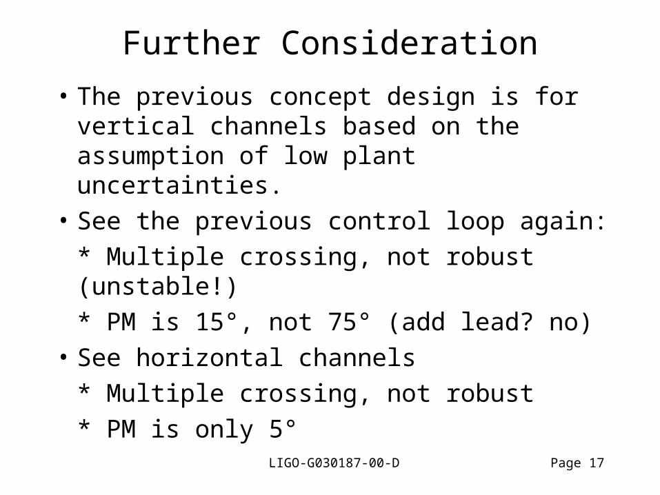
Further Consideration
• The previous concept design is for vertical channels based on the assumption of low plant uncertainties.
• See the previous control loop again:
* Multiple crossing, not robust (unstable!)
* PM is 15°, not 75° (add lead? no)
• See horizontal channels
* Multiple crossing, not robust
* PM is only 5°

LIGO-G030187-00-D Page 18
100
101
-200
-150
-100
-50
0
50
100
150
200
250
300
100
101
10-3
10-2
10-1
100
101
-1
-2
-1-2
+1
-90°
-180°
|G(s)|
Vertical Loop (Concept Design)|H(s)|
Phase Margin180-15-90+=75°-
180-75-90+=15°-
|T(s)|Closed Loop
15 reduction 1-3Hz
|G(s)H(s)|Loop Gain
Multiple Crossings
After StructureModification
(Position feedback will be used for <0.5Hz)

LIGO-G030187-00-D Page 19
100
101
-200
-100
0
100
200
300
100
101
10-3
10-2
10-1
100
101
100
101
-150
-100
-50
0
50
100
150
-1
-2
-1-2
+1
-90°
-180°
|G(s)|
Horizontal Loop (Concept Design)|H(s)|
Phase Margin180-85-90+=5°-
|T(s)|Closed Loop
15 reduction 1-3Hz
|G(s)H(s)|Loop Gain
Multiple Crossings
After StructureModification
(Position feedback will be used for <0.5Hz)

LIGO-G030187-00-D Page 20
Suggestion for Feedback Control
* Modal Decomposition SISO Control.
Questions (SISO):
1) how good is the decomposition?
2) how large are the peaks of flexible modes?
Other rigid-body modes from non-perfect decomposition
Flexible modes
Dominant rigid-body mode
|·|
dF
V
1oX
X

LIGO-G030187-00-D Page 21
Suggestions on Structure Modification(to make control easier)
• Add constrained layer (viscoelastic) damping to the beam structure (to damp the bending modes)
• Make the joints stiffer; add some damping to the joints; or add another beam
• Reduce the coupling between tank and the frame.

LIGO-G030187-00-D Page 22
Conclusions
• Multiple lightly damped modes close to crossover make control difficult– Instability– Amplification of disturbances
• Modal control may decrease their relative magnitudes.
• Easiest approach to robust performance: structural damping.
• Optimal MIMO Control can improve the performance, but requires a good model

LIGO-G030187-00-D Page 23
Other Control Schedules Discussed
• Osamah: low frequency crossing with high order controller
• Dave: notch filter
• Rich, David and Denis: high frequency crossing

LIGO-G030187-00-D Page 24
Appendix
LIGO-G030187-00-D Page 25
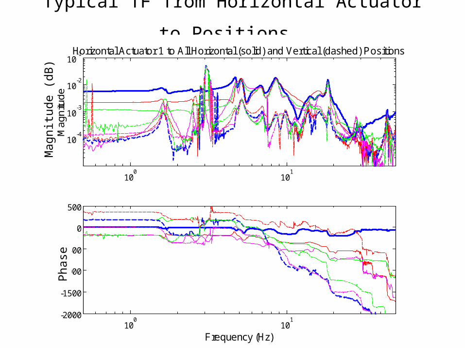
Typical TF from Horizontal Actuator to Positions
100
101
10-4
10-3
10-2
10-1
Ma
gn
itud
eHorizontal Actuator 1 to All Horizontal (solid) and Vertical (dashed) Positions
100
101
-2000
-1500
-1000
-500
0
500
Frequency (Hz)
Ph
ase
Mag
nitu
de (
dB)
Pha
se

LIGO-G030187-00-D Page 26
100
101
10-4
10-3
10-2
10-1
Ma
gn
itud
eVertical Actuator 3 to All Vertical (solid) and Horizontal (dashed) Positions
100
101
-2000
-1500
-1000
-500
0
500
Frequency (Hz)
Ph
ase
Typical TF from Vertical Actuator to Positions M
agni
tude
(dB
) P
hase

LIGO-G030187-00-D Page 27
Out-of-Plane Bending Modes
20.38Hz
20.41Hz
Out-of-Plane Beam Bending Related

LIGO-G030187-00-D Page 28
Mode Shapes
1.3Hz
1.7Hz
(low-freq, measurement is not reliable)

LIGO-G030187-00-D Page 29
Mode Shapes
2.50Hz
2.97Hz

LIGO-G030187-00-D Page 30
Mode Shapes
4.41Hz
4.99Hz

LIGO-G030187-00-D Page 31
Mode Shapes
6.86Hz
8.33Hz

LIGO-G030187-00-D Page 32
Mode Shapes
9.25Hz

LIGO-G030187-00-D Page 33
Mode Shapes
10.9Hz
9.82Hz