lightweight optimization of bus frame structure ... optimization of bus frame structure considering...
TRANSCRIPT

Lightweight optimization of bus frame structure considering rollover safety
C. C. Liang & G. N. Le Department of Mechanical and Automation Engineering, Da-Yeh University, Taiwan, ROC
Abstract
The transit bus is an important part of public transportation, while in a bus rollover accident the deforming superstructure seriously threatens the lives of the passengers and the crew in the bus. Thus, bus rollover safety and how to design a bus superstructure with a good stiffness of vehicle frame is an important task for bus manufacturers. The legislation regulation number 66 of the Economic Commission for Europe (ECE R66) of bus rollover protection has been enforced for bus rollover protection. Strengthening the bus frame to maintain survivor space and reduce occupant injury is necessary following the issue of ECE R66, whilst lightweight structures in bus body design have also been highlighted. Therefore, this study presents a lightweight optimization considering the bus rollover crashworthiness design. In this study, the side wall section, and the roof section of bus frame are analyzed based on energy absorption ability in order to specify the design variables. With the aim of improving both the deformation of the bus frame versus the vehicle’s survivor space and the body skeleton density of the vehicle structure, optimization is performed by LS-OPT with the successive respond surface method (SRSM), where LS-DYNA is used as the FE solver. An optimal vehicle model was obtained with a lightweight structure and crashworthiness following ECE R66. The findings could be used by automobile manufacturers in a new design of bus superstructure, incorporating the rollover safety legislation and lightweight optimization. Keywords: bus rollover, superstructure, ECE R66, energy absorption, LS-DYNA, optimization, lightweight, LS-OPT.
www.witpress.com, ISSN 1743-3541 (on-line) WIT Transactions on Ecology and The Environment, Vol 155, © 2012 WIT Press
doi:10.2495/SC120992
The Sustainable City VII, Vol. 2 1185

1 Introduction
Today, transit buses are an integral part of each nation’s transportation system. Although buses are one of the safest means of transportation, occupant injuries and fatalities in bus crashes do occur. Many heart-breaking bus accidents happen. In Europe, bus and coach manufacturers also are focusing more on passenger safety in case of catastrophic rollover accidents. Spanish data from 1995 to 1999 showed a rollover frequency of 4 percent of all coach accidents on roads and highways, and the risk for fatalities in a rollover was five times higher than in any other type of coach accident [1]. Another statistic of Fatality Analysis Reporting System (FARS) also showed that rollover occurs less frequently than all other types of automotive accidents, but the probability of fatalities and severe injuries is more in rollover type accidents. Thus, rollover strength has become an important issue for bus and coach manufacturers. For this problem, Europe has enforced bus rollover safety regulation and standard to prevent catastrophic rollover accidents. Economic Commission for Europe had enforced Regulation No.66 (ECE R66) for the Bus Strength of Superstructure since 1987 in order to provide protection to the bus and coach occupants during rollover accidents through the maintenance of a survival space [2, 3]. In this research, a complete study based on optimal design of bus frame structure considering the rollover strength has been carried out. In which aspect of bus rollover safety standard will be also included. A complete procedure lightweight and safety design of bus frame considering rollover strength has been executed in this paper. The ability of energy absorption not only concern on the highest energy absorption region that also concern on lowest energy absorption region. It is believed that this research project will provide a profound understanding of lightweight and safety design of the bus frame structure considering rollover strength.
2 LS-DYNA introduction
LS-DYNA was developed by LSTC (Livermore Software Technology Cooperation). It is a multifunctional applicable explicit and implicit Finite-Element program to simulate and analyze highly nonlinear physical phenomena obtained in real world problems. Usually such phenomena manifest large deformations within short time durations, e.g. crashworthiness simulations. The significant features of LS-DYNA are the fully automatic definitions of contact areas, the large library of constitutive models, the large library of element types and the special implementations for the automobile industry [4, 5]. This study uses the FE software to carry out the bus rollover and the bus roof compressing simulation. The behavior of the bus rollover simulation belongs to the area of transient, dynamic, nonlinear, large deformed problems. And the bus roof compressing simulation belongs to the area of transient, quasi-static, nonlinear, large deformed problems. The Finite Element Analysis code, LS-
1186 The Sustainable City VII, Vol. 2
www.witpress.com, ISSN 1743-3541 (on-line) WIT Transactions on Ecology and The Environment, Vol 155, © 2012 WIT Press

DYNA, is a favorite tool for both of these two problems which often include contact and impact. The main solution is based on explicit time integration.
3 Numerical analysis procedures for bus rollover protection
3.1 ECE R 66 numerical procedure
Computer simulation of a rollover test on a complete vehicle is an equivalent approval method, and is becoming an irreplaceable mathematical tool in the vehicle design and development process. It allows manufacturers to test designs and safety features virtually in the crash scenario until they obtain the safest and optimum design, thus saving time and money in developing costly prototypes. The analysis processes are as follows:
(1). Build the testing model from a full scale bus model and tilting platform model.
(2). Based on the testing conditions the material card, boundary condition card, and contact card are set up and applicable load is applied to this testing model.
(3). Determine the already tilting angle to reduce computing time. (4). Use LS-DYNA 971 software to carry out the simulation of a rollover
accident of this testing model. (5). Evaluate the status of testing model after completion of the test and
obtain simulation results. The testing model is established by full scale bus model as in Fig. 1 and tilting platform model as in Fig. 2.
Figure 1: Full-scale FE bus model.
Figure 2: Tilting platform model.
3.2 Computational models
This FE vehicle model used for simulation is based on a full scale bus model developed at Da-Yeh University, Taiwan for rollover crashworthiness investigation and evaluation of reinforcement structures [6-8]. It includes 68132 elements. These consist of 67084 quadrilateral elements, 914 triangular elements, 35 hexagons and 99 mass elements. All deformable parts are modeled
www.witpress.com, ISSN 1743-3541 (on-line) WIT Transactions on Ecology and The Environment, Vol 155, © 2012 WIT Press
The Sustainable City VII, Vol. 2 1187
with the 4-noded Belytschko-Tsay shell elements with three integration points through the shell thickness. The CG (Center of Gravity) of the vehicle was measured using a test platform at the ARTC (Automotive Research & Testing Center, Taiwan, R.O.C). The measured values were in good agreement with the ones coming from the FEA model. To exactly match the measures and calculated CG, the CG of engine, gearbox and the axles were fine tuned in the FEA model. The unloaded vehicle weight is 7716.47 kg (7.71647 ton), and its capacity is 49 passengers. The vehicle size and its position of CG are shown in Fig. 1. The FE modeling is done by the FEMB (pre-processing finite element model builder) of LS-DYNA, and calculations were made by means of a non-linear, explicit, 3-D, dynamic FE computer code LS-DYNA.
3.3 Survivor space definition of a bus
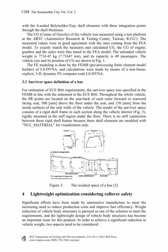
For estimation of ECE R66 requirements, the survivor space was specified in the FEMB in line with the statement in the ECE R66. Throughout the whole vehicle, the SR points are located on the seat-back of each outer forward or rearward facing seat, 500 [mm] above the floor under the seat, and 150 [mm] from the inside surfaces of the side walls of the vehicle. The model of the survivor space consists of a rigid shell frame in each section along the vehicle interior (Fig. 3), rigidly mounted in the stiff region under the floor. There is no stiff connection between these rigid shell frames because these shell elements are modeled with “NUL_MATERIAL” for visualization only.
Figure 3: The residual space of a bus [3].
4 Lightweight optimization considering rollover safety
Significant efforts have been made by automotive manufacture to meet the increasing need to reduce production costs and improve fuel efficiency. Weight reduction of vehicle body structures is pursued as one of the solution to meet the requirements, and the lightweight design of vehicle body structures has become an important issue for this purpose. In order to achieve a significant reduction in vehicle weight, two aspects need to be considered:
1188 The Sustainable City VII, Vol. 2
www.witpress.com, ISSN 1743-3541 (on-line) WIT Transactions on Ecology and The Environment, Vol 155, © 2012 WIT Press
The application of alternative lighter materials such as aluminum and composites replacing conventional steels.
A reduction in the number and weight of parts in the whole body structure without replacing steel.
The investigation in this part of the study concerned with the latter, which not only reduces the production cost reasonably but also avoids extra tooling investments due to the replacement of material and the corresponding changes in joining technology.
4.1 Lightweight and safety optimization of bus superstructure
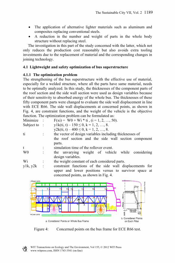
4.1.1 The optimization problem The strengthening of the bus superstructure with the effective use of material, especially for a welded structure, where all the parts have same material, needs to be optimally analyzed. In this study, the thicknesses of the component parts of the roof section and the side wall section were used as design variables because of their sensitivity to absorbed energy of the whole bus. The thicknesses of these fifty component parts were changed to evaluate the side wall displacement in line with ECE R66. The side wall displacements at concerned points, as shown in Fig. 4, are constraint functions, and the weight of the vehicle is the objective function. The optimization problem can be formulated as: Minimize : F(xi) = W0 + Wi * ti , (i = 1, 2, …, 50). Subject to : y1k(ti, t) – 150 ≤ 0, k = 1, 2, …, 8. y2k(ti, t) – 400 ≤ 0, k = 1, 2, …, 8. ti : the vector of design variables including thicknesses of the roof section and the side wall section component parts. t : simulation time of the rollover event. W0 : the unvarying weight of vehicle while considering
design variables. Wi : the weight constant of each considered parts. y1k, y2k : constraint functions of the side wall displacements for upper and lower positions versus to survivor space at concerned points, as shown in Fig. 4.
Figure 4: Concerned points on the bus frame for ECE R66 test.
www.witpress.com, ISSN 1743-3541 (on-line) WIT Transactions on Ecology and The Environment, Vol 155, © 2012 WIT Press
The Sustainable City VII, Vol. 2 1189
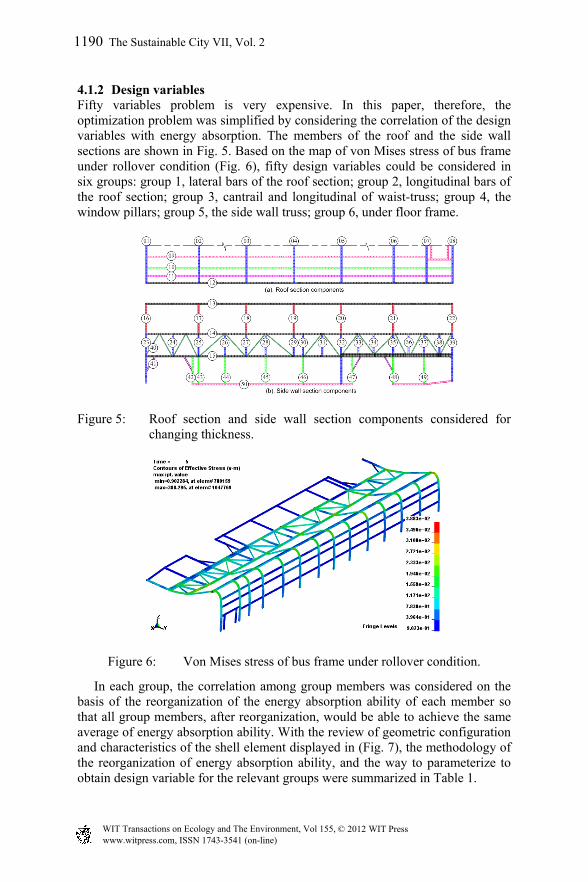
4.1.2 Design variables Fifty variables problem is very expensive. In this paper, therefore, the optimization problem was simplified by considering the correlation of the design variables with energy absorption. The members of the roof and the side wall sections are shown in Fig. 5. Based on the map of von Mises stress of bus frame under rollover condition (Fig. 6), fifty design variables could be considered in six groups: group 1, lateral bars of the roof section; group 2, longitudinal bars of the roof section; group 3, cantrail and longitudinal of waist-truss; group 4, the window pillars; group 5, the side wall truss; group 6, under floor frame.
Figure 5: Roof section and side wall section components considered for changing thickness.
Figure 6: Von Mises stress of bus frame under rollover condition.
In each group, the correlation among group members was considered on the basis of the reorganization of the energy absorption ability of each member so that all group members, after reorganization, would be able to achieve the same average of energy absorption ability. With the review of geometric configuration and characteristics of the shell element displayed in (Fig. 7), the methodology of the reorganization of energy absorption ability, and the way to parameterize to obtain design variable for the relevant groups were summarized in Table 1.
1190 The Sustainable City VII, Vol. 2
www.witpress.com, ISSN 1743-3541 (on-line) WIT Transactions on Ecology and The Environment, Vol 155, © 2012 WIT Press

Figure 7: Geometry configuration of window pillars and side wall pillars.
Table 1: Reorganization of energy absorption ability and specification of design variable.
With x1, x2, x3, x4, x5, x6 as design variables for the group 1 (i = 1~8), group 2 (i = 9~11), group 3 (i = 12~15), group 4 (i = 16~22), group 5 (i = 23~40), group 6 (i = 41~50). The fifty variables problem is, therefore, made simple and is now a six variables optimization problem, formulated as: Minimize : F(x) = W0 + W1 × x1 + W2 × x2 + W3 × x3 + W4 × x4 + W5 × x5 + W6 × x6 Subject to : y1k(x1, x2, x3, x4, x5, x6, t) – 150 ≤ 0, k = 1, 2, …, 8. y2k(x1, x2, x3, x4, x5, x6, t) – 400 ≤ 0, k = 1, 2, …, 8. x1~x6 : the design variables for the concerned groups. t : simulation time of the rollover event. W0 : the unvarying weight of the vehicle while considering the design parts. W1~W6 the weight constants with respect to the concerned groups. y1k, y2k : constraint functions of the side wall displacements for
upper and lower areas versus survivor space at concerned points, as shown in Fig. 4.
A solution was reached by use of the LS-OPT and LS-DYNA combination for optimization analysis; the optimization method is SRSM.
www.witpress.com, ISSN 1743-3541 (on-line) WIT Transactions on Ecology and The Environment, Vol 155, © 2012 WIT Press
The Sustainable City VII, Vol. 2 1191

4.1.3 Optimization process The optimization process of LS-OPT is shown in Fig. 8. Preparation of inputs included design variables, range of design variables, FE solver, parameterized FE file as well as sampling type of design of experiment (DOE), constraint and objective functions, etc. for generating the inputs of simulation jobs automatically inside the optimization process. All of them were managed by the LS-OPT main menu. Program files for automatic execution included COM, LSOPT_INPUT and LSOPT_DB files that are automatically generated for standard input of LS-OPT processing from preparation data. The output of the optimization process was a LSOPT_REPORT file. Other ways of output can be displayed in the viewer tab of LS-OPT’s main menu.
Figure 8: LS-OPT optimization process.
1192 The Sustainable City VII, Vol. 2
www.witpress.com, ISSN 1743-3541 (on-line) WIT Transactions on Ecology and The Environment, Vol 155, © 2012 WIT Press
4.1.4 Verification of design
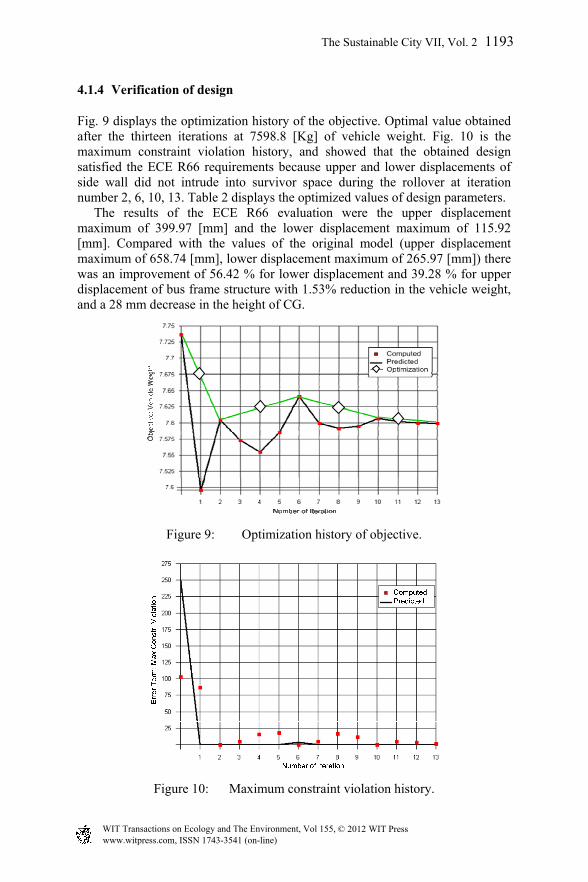
Fig. 9 displays the optimization history of the objective. Optimal value obtained after the thirteen iterations at 7598.8 [Kg] of vehicle weight. Fig. 10 is the maximum constraint violation history, and showed that the obtained design satisfied the ECE R66 requirements because upper and lower displacements of side wall did not intrude into survivor space during the rollover at iteration number 2, 6, 10, 13. Table 2 displays the optimized values of design parameters. The results of the ECE R66 evaluation were the upper displacement maximum of 399.97 [mm] and the lower displacement maximum of 115.92 [mm]. Compared with the values of the original model (upper displacement maximum of 658.74 [mm], lower displacement maximum of 265.97 [mm]) there was an improvement of 56.42 % for lower displacement and 39.28 % for upper displacement of bus frame structure with 1.53% reduction in the vehicle weight, and a 28 mm decrease in the height of CG.
Figure 9: Optimization history of objective.
Figure 10: Maximum constraint violation history.
www.witpress.com, ISSN 1743-3541 (on-line) WIT Transactions on Ecology and The Environment, Vol 155, © 2012 WIT Press
The Sustainable City VII, Vol. 2 1193
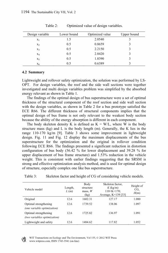
Table 2: Optimized value of design variables.
Design variable Lower bound Optimized value Upper bound
x1 1.5 2.0540 3
x2 0.5 0.8659 3
x3 0.5 2.2150 3
x4 0.5 2.8420 3
x5 0.5 1.8390 3
x6 0.5 0.6389 3
4.2 Summary
Lightweight and rollover safety optimization, the solution was performed by LS-OPT. For design variables, the roof and the side wall sections were together investigated and multi design variables problem was simplified by the absorbed energy relevant as shown in Table 1. The findings of the optimal design of bus superstructure were a set of optimal thickness of the structural component of the roof section and side wall section with the design variables, as shown in Table 2 for a bus prototype satisfied the ECE R66. The different thickness of structural components implies that the optimal design of bus frame is not only relevant to the weakest body section because the ability of the energy absorption is different in each component. The body skeleton density K is defined as K = W/L, where W is the body structure mass (kg) and L is the body length (m). Generally, the K lies in the range 110-170 kg/m [9]. Table 3 shows some improvement in lightweight design. Fig. 11 and Fig. 12 display the maximum displacements of the bus superstructure for the optimization and the original in rollover condition following ECE R66. The findings presented a significant reduction in distortion configuration of bus body (56.42 % for lower displacement and 39.28 % for upper displacement of bus frame structure) and 1.53% reduction in the vehicle weight. This is consistent with earlier findings suggesting that the SRSM is strong and effective optimization analysis method, and is used for optimal design of structure, especially complex one like bus superstructure.
Table 3: Skeleton factor and height of CG of considering vehicle models.
Vehicle model Length, L (m)
Body structure mass, W
(kg)
Skeleton factor, K (kg/m)
110<K<170; Average, K=139 [33]
Height of CG,
H(m)
Original 12.6 1602.31 127.17 1.080
Optimal strengthening (one variable optimization)
12.6 1739.52 138.06 1.097
Optimal strengthening (two variables optimization)
12.6 1725.82 136.97 1.091
Lightweight and safety 12.6 1484.62 117.82 1.052
1194 The Sustainable City VII, Vol. 2
www.witpress.com, ISSN 1743-3541 (on-line) WIT Transactions on Ecology and The Environment, Vol 155, © 2012 WIT Press
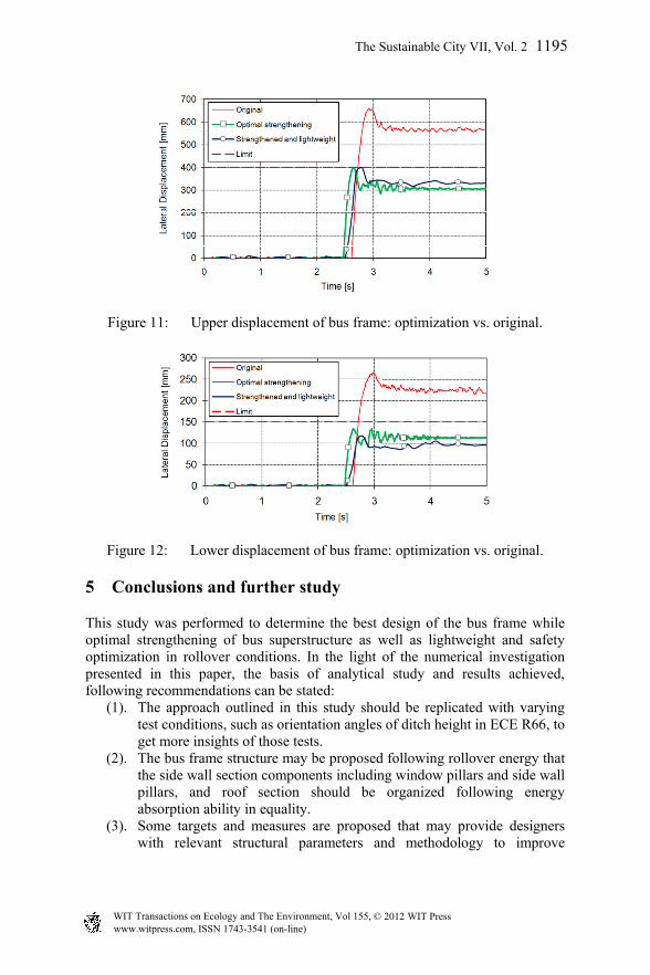
Figure 11: Upper displacement of bus frame: optimization vs. original.
Figure 12: Lower displacement of bus frame: optimization vs. original.
5 Conclusions and further study
This study was performed to determine the best design of the bus frame while optimal strengthening of bus superstructure as well as lightweight and safety optimization in rollover conditions. In the light of the numerical investigation presented in this paper, the basis of analytical study and results achieved, following recommendations can be stated:
(1). The approach outlined in this study should be replicated with varying test conditions, such as orientation angles of ditch height in ECE R66, to get more insights of those tests.
(2). The bus frame structure may be proposed following rollover energy that the side wall section components including window pillars and side wall pillars, and roof section should be organized following energy absorption ability in equality.
(3). Some targets and measures are proposed that may provide designers with relevant structural parameters and methodology to improve
www.witpress.com, ISSN 1743-3541 (on-line) WIT Transactions on Ecology and The Environment, Vol 155, © 2012 WIT Press
The Sustainable City VII, Vol. 2 1195

rollover safety and lightweight design and reduce design lead time for a new product.
(4). Bus rollover crashworthiness design procedure followed ECE R66 in optimization manner should be used for a new proposed vehicle with the methodology guidelines presented in this study for optimal strengthening as well as reducing the vehicle weight of a bus vehicle that meets required safety standards.
References
[1] Martinez L., Aparicio F., Garcia A., Paez J., Ferichola G., (2003) “Improving occupant safety in coach rollover,” INSIA, Polytechnic University of Madrid, Spain.
[2] JASIC, (1998). ECE Regulation No.66 S1 - Strength of Super Structure, Economic Commission for Europe, pp1-19.
[3] JASIC, (2006). ECE Regulation No.66 01 - Strength of Superstructure, Economic Commission for Europe, pp 1-49.
[4] J.O. Hallquist, (2006). LS-DYNA Theoretical Manual, Livermore Software Technology Corporation.
[5] LSTC, (2007). LS-DYNA Users Manual, Livermore Software Technology Corporation.
[6] X.-T. Chiu, (2007). The design and Evaluation of Reinforcement Structure for Bus Frame. Master thesis, Da-Yeh University.
[7] Y.-X. Chai, (2005). Numerical Simulation and Analysis of Bus Rollover, Master thesis, Da-Yeh University.
[8] R.-H. Chang, (2006). A Study on Increasing Structural Strength of Bus, Master thesis, Da-Yeh University.
[9] K. Lan, J. Chen, and J. Lin, (2004). Comparative analysis for bus side structures and lightweight optimization. Proc. Instn Mech, Engrs Vol.218 Part D: J. Automotive Engineering.
1196 The Sustainable City VII, Vol. 2
www.witpress.com, ISSN 1743-3541 (on-line) WIT Transactions on Ecology and The Environment, Vol 155, © 2012 WIT Press