lightning protection: securing higher reliability and meeting the new standards
TRANSCRIPT
Lightning Protection: Securing Higher Reliability and Meeting the New StandardsSandia National Laboratories – 2016 Wind Turbine Blade Workshop
EMPOWERING YOU TO TAKE CHARGE Kim Bertelsen – Global Lightning Protection Services A/S
OUTLINE1. Introduction
2. News on IEC 61400-24
3. Lightning Damage Analysis
4. Explanations on failure mechanisms
5. Robustness in design
6. Lightning Monitoring
7. Conclusions

We are a full service provider in Lightning
We provide solutions for:
Wind Energy Aerospace Buildingsand Plants

We are a global provider
We offer lightning solutions for mission critical industries and international customers.
• Established in 2007• 42 employees• Present in Denmark, China and USA

Our services & solutions
Infield Inspection
ServicesEngineering
ProjectsLaboratory
TestingHigh
QualitySolutions

EMPOWERING YOU TO TAKE CHARGE Lightning is predictable, controllable and the risk is preventable.

IEC 61400-24 Wind turbines – Part 24 Lightning ProtectionThe1steditionwaspublishedin2010,2ndversionwillbeissuedasaCommitteeDraft(CD)inOctober2016followingthenextmeetinginLisbon,Portugal
• TestisbecomingmandatoryincludingHigh-voltagetestandHigh-currentphysicaldamagetesting– notonlyforbladesbutfortheentirewindturbineapplication.
• Descriptionofsimilarityparametersbetweenbladetypes,wherethesameLPsystemcanbeusedacrossabladefamilywithoutrequiringretesting
• Thestandardincludesbladeexposuredefinitions,basedonpublishedfielddata• Bladezoning/Environmentaldefinitions isrequired• Definitionoflifetimeisrequired• Recognitionofnumericalsimulation,butrequirementsformodellingverification• Improvedriskassessmentguidelinesincludingwinterlightningandupwardinitiated
strikes.• RequirementsforLightningMonitoring– ifincluded
News on IEC 61400-24

Lightning Damages Analysis508 wind turbines (total power 997 MW) during 5 years operation in central USABlade length: 35 – 45 m; 304 damages
0.0%
10.0%
20.0%
30.0%
40.0%
50.0%
60.0%
70.0%
1 2 3 4 5 6 7 8 9 10 11 12 13 14 15 16 17 18 19 20 21 22 23 24 25
Totald
amages
Distance fromthe tip[m]
Fiberglassblades
0.0%
10.0%
20.0%
30.0%
40.0%
50.0%
60.0%
70.0%
1 2 3 4 5 6 7 8 9 10 11 12 13 14 15 16 17 18 19 20 21 22 23 24 25
Totald
amages
Distance fromthe tip[m]
Fiberglass/CFCblades
Source:AnnaCandelaGaroleraetal,IEEEpaper
Lightning Damages Analysis
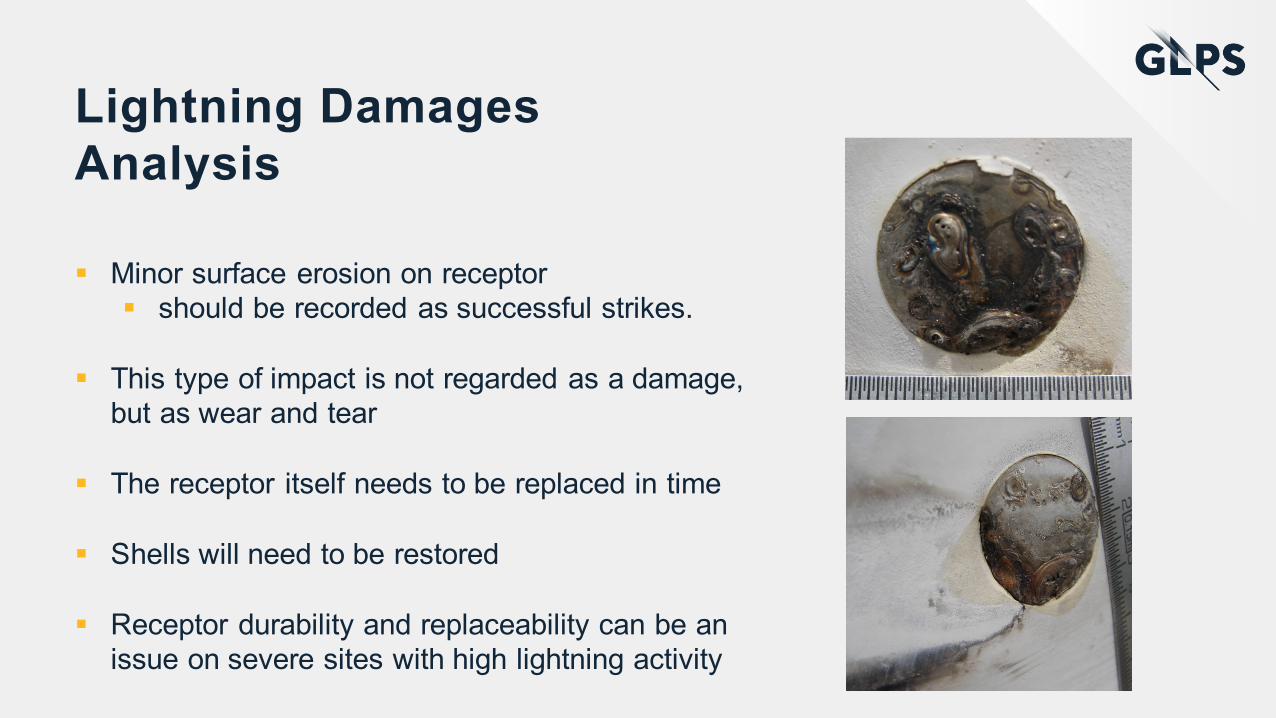
§ Minor surface erosion on receptor § should be recorded as successful strikes.
§ This type of impact is not regarded as a damage, but as wear and tear
§ The receptor itself needs to be replaced in time
§ Shells will need to be restored
§ Receptor durability and replaceability can be an issue on severe sites with high lightning activity
Lightning Damages Analysis
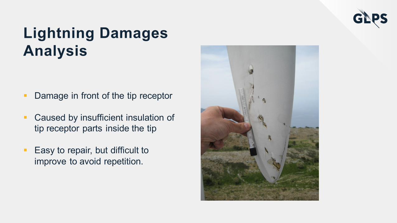
§ Damage in front of the tip receptor
§ Caused by insufficient insulation of tip receptor parts inside the tip
§ Easy to repair, but difficult to improve to avoid repetition.

Lightning Damages Analysis
§ Most common damage close to the tip
§ Caused by insufficient insulation of conductor system
§ Relatively easy to repair
§ Often the lightning system is left as it was – resulting in same damage again

Lightning Damages Analysis
§ Attachment through shell to lightning cable - Shell delamination
§ Caused by insufficient insulation of conductor system
§ Relatively easy to repair
§ Often the lightning system is left as it was – resulting in same damage again

Lightning Damages Analysis
§ More severe damage with broken carbon structure
§ Caused by flash-over from lightning cable to carbon structure – due to missing coordination between the two systems
§ Shells are detached requiring significant repair work – eventually the blade needs to be replaced
§ Difficult to improve system during repair for avoiding repetition
Lightning Damages Analysis
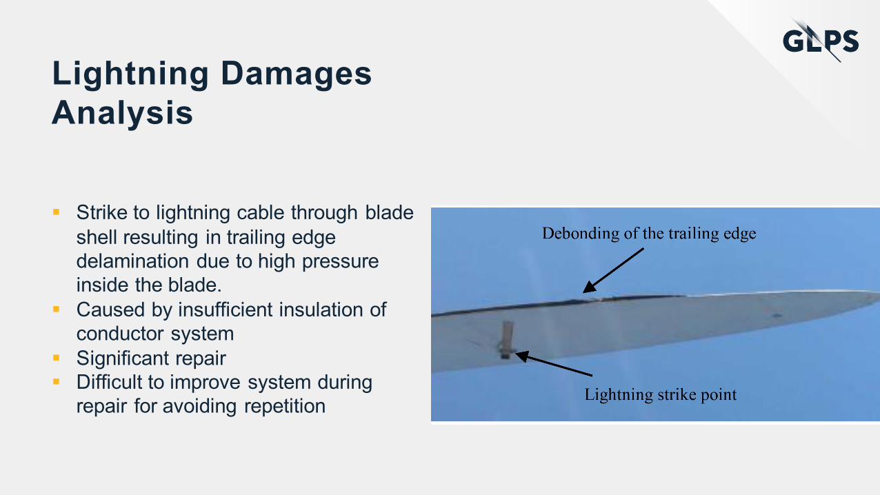
§ Strike to lightning cable through blade shell resulting in trailing edge delamination due to high pressure inside the blade.
§ Caused by insufficient insulation of conductor system
§ Significant repair§ Difficult to improve system during
repair for avoiding repetition
Lightning Damages Analysis
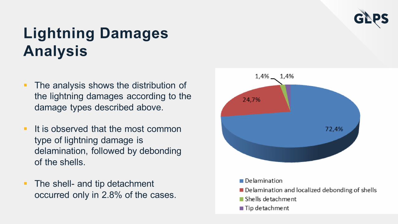
§ The analysis shows the distribution of the lightning damages according to the damage types described above.
§ It is observed that the most common type of lightning damage is delamination, followed by debondingof the shells.
§ The shell- and tip detachment occurred only in 2.8% of the cases.

Lightning Damages Analysis
§ The analysis shows the distribution of the lightning damages according to the damage types described above.
§ It is observed that the most common type of lightning damage is delamination, followed by debondingof the shells.
§ The shell- and tip detachment occurred only in 2.8% of the cases.

Explanations on failure mechanisms§ The lightning event is divided into different stages:
§ Leader Inception – where the turbine develops leaders due to high electric fields – and send out leaders toward the incoming lightning.
§ Leaders Interception – where an incepted leader connects with an cloud leader
§ Current conduction Phase § First Return Stroke§ Subsequent Return strokes§ Long Duration Stroke
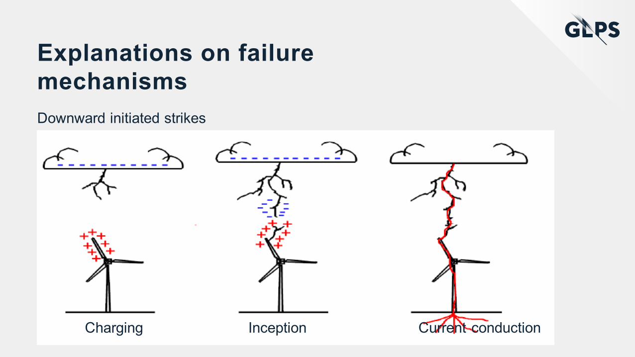
Explanations on failure mechanismsDownward initiated strikes
Charging Inception Current conduction

Explanations on failure mechanismsUpward initiated strikes

Explanations on failure mechanisms§ Likelihood of upward lightning
increases with turbine effectiveheight
§ Often triggered by intra clouddischarges
§ Will not appear on public lightning detection and is therefore not included in i.e.
§ NLDN from Vaisala

Explanations on failure mechanisms
§ The root cause of most lightning damages are lightning leader initiation from internal parts –and not only from intended receptors
DowncondutorWeb/sparTipreceptorbase Tipreceptor
Initialleader
Cableoverlamination

Explanations on failure mechanisms
§ In testing the samephenomenon is seemlike this

Explanations on failure mechanisms
§ Or like this……
§ In this area there is noreceptors at all

Robustness in designWhat is robustness?§ Step 1:
§ We need to implement a LP system where the internal conductive part cannot incept streamers – which requires careful insulation coordination
§ Only receptors can incept streamers – if the system should work.§ The LP system needs to pass all high-voltage strike attachment tests and High-
current physical damage tests – to show a strong tip receptor design – as well as a strong down conductor/interconnector system.
§ Step 2:§ Robust LP systems need to be well tested to the limits - and beyond to define
design margins. § Lifetime tests must be carried out to document that no degradation is taking place
on non-replaceable parts – and to document wear and tear§ The LP system needs to be maintained regularly based on life time definitions –
and based on accumulated impacts to the specific blade.

Robustness in designBlade Zoning§ GLPS has suggested a blade zoning concept to focus the efforts to the
near-tip area.
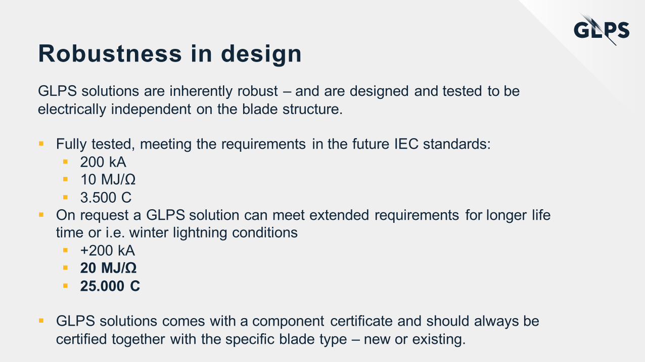
Robustness in designGLPS solutions are inherently robust – and are designed and tested to be electrically independent on the blade structure.
§ Fully tested, meeting the requirements in the future IEC standards:§ 200 kA§ 10 MJ/Ω§ 3.500 C
§ On request a GLPS solution can meet extended requirements for longer life time or i.e. winter lightning conditions§ +200 kA§ 20 MJ/Ω§ 25.000 C
§ GLPS solutions comes with a component certificate and should always be certified together with the specific blade type – new or existing.

Carbon- and Complex blades§ Carbon blades and complex blade including sensors, deicing systems etc.
needs special attention.
§ No other electrical systems in the blade can be kept floating, but needs to be carefully integrated into the lightning system.

Robustness in design
§ The tip solution should ideally be a premanufactured component, that utilizes all the insulation and conductions capabilities need to demonstrate robustness in test and real life operation.

Robustness in design
§ GLPS tip

Robustness in design
§ GLPS side receptor

Robustness in design
§ The tip LP system tested as a naked system without blade shells.
§ The same test program as for a final verification test needs to be followed and passed.
§ Here attachment to the tip receptor
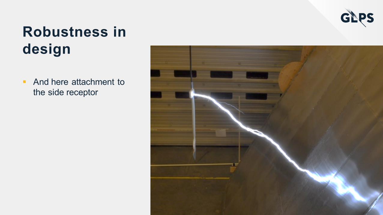
Robustness in design
§ And here attachment to the side receptor

Robustness in design
§ LP system implemented in a blade tip

Robustness in design
§ Glue is applied….

Robustness in design
§ Retrofit job almost done….

Robustness in design
§ Final verification test

Lightning Monitoring
Lightning Key Data® System
§ Avoid unnecessary inspections and expensive downtime
§ Lightning Key Data® System measures the lightning key figures when it strikes and provides you with valuable data for making the best decisions.§ Peak current [kA]§ Specific Energy [MJ/Ω]§ Charge content [C]§ Maximum rise time [kA/μs]

Lightning MonitoringGPSAntenna PowerSupply
SPDs
PowersupplyentryHeavyEMCbox
Comm.output
RecorderPCBSensorcablesentry
Amplifiers Sensor shieldingclamps

Lightning Monitoring§ Measurement characteristics
§ Current amplitude: +/- 240kA§ Frequency range (-3dB range): 30mHz - 1MHz§ Sampling frequency: 10MHz§ Time frame recorded: 1.5s§ Length of recorded waveform: 15M samples§ Trigger level: Adjustable§ Pre trigger: 100ms§ Measurement resolution: 16bit§ Time stamp accuracy: GPS/1ms
§ Backup of data to internal industrial grade SD card§ Four characteristic parameters calculated from the full waveform§ Full data set available after each measurement§ Continuous measurement in full resolution of two subsequent events§ Recording of all three channels simultaneously

Lightning Monitoring
§ The control unit is supposed to be installed in the hub – or in one of the blade roots.
§ The sensors can be installed in different positions depending on the LP systems configuration § Inside blade root on down
conductor§ On transfer system§ Around blade

Lightning Monitoring
§ Final verification test

Lightning Monitoring
§ Parameter output
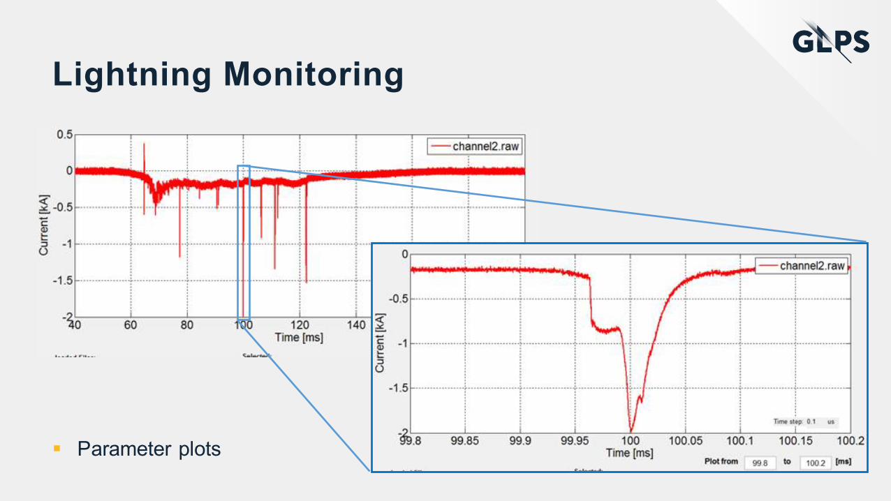
Lightning Monitoring
§ Parameter plots

Conclusions§ Lightning is predictable, controllable and the risk is preventable.
§ A new version of the lightning standard IEC 61400-24 will be released soon.
§ Damages most often occurs to the outermost 1m of the blade, why this should be the focus. The rest of the blade should not be forgotten – but protection is not so demanding.
§ Robustness in LP systems can be achieved in a good combination between design and verification.
§ Blade with carbon fiber and complex blades with sensors and deicing systems needs special attention
§ Online lightning monitoring is available

EMPOWERING YOU TO TAKE CHARGE Thank you!

EMPOWERING YOU TO TAKE CHARGE

Contact us
Global Lightning Protection Services A/S
HI-Park 445DK-7400 HerningDenmark
[email protected]+45 70 26 02 11
global-lightning.com