lightning protection: history and modern approaches packet/ams 06.pdf · lightning protection:...
TRANSCRIPT

Lightning Protection History and
Modern Approaches
Department of Electrical and Computer Engineering
University of Florida Gainesville
86th AMS Annual Meeting
2nd Conference on Meteorological Applications of Lightning
Atlanta Georgia January 29 ndash February 2 2006
Vladimir A Rakov
2
2
Lightning Protection History and Modern Approaches
1 Franklin rod system
2 ldquoFaraday cagerdquo approach
3 Placement of air terminals
4 Behavior of grounding systems under direct lightning strike
conditions
5 Bonding Requirements
6 Non-conventional approaches to lightning protection
3
1 Franklin rod system (first described in 1753)
Lightning protection system for houses proposed (most likely by G Ch Lichtenberg) in
1778 Adapted from Wiesinger and Zischank (1995)
Air terminal
Down conductor
Ground terminal
4
1 Franklin rod system
Metallic roofs whose thickness is 48 mm (316 in) or greater do not require air
terminals (NFPA 780)
Air terminal
Down conductor
Ground terminal
Air terminal locations (UL 96A Fig 62 1998)
A= 20 feet (6 m) maximum
spacing for 10 inch (254
mm) air terminal height or
25 feet (76 m) maximum
spacing for 24 inch (610
mm) air terminal height
B= 2 feet (610 mm) maximum
spacing from corner roof
edge or ridge end
5
In 1876 James Clerk Maxwell
proposed that a gunpowder building
be completely enclosed with metal
of sufficient thickness forming what
is now referred to as a Faraday
cage
If lightning were to strike a metal-
enclosed building the current would
be constrained to the exterior of the
metal enclosure and it would not
even be necessary to ground this
enclosure In the later case the
lightning would merely produce an
arc from the enclosure to earth
The Faraday cage effect is provided
by all-metal cars and airplanes
Modern steel-frame buildings with
reinforcing metal bars in the
concrete foundation connected to
the building steel provide a good
approximation to a Faraday cage
The general principles of topological
shielding Adapted from Vance (1980)
2 ldquoFaraday cagerdquo approach
Zone 1
Zone 3
Zone 1
Zone 2
1
10
22 3
Zone 0
SPD = Surge Protective Device
6
2 ldquoFaraday cagerdquo approach
Lightning strike to a car with a live rabbit inside Courtesy of S Sumi
7
Video frame of a lightning strike to an aircraft on takeoff from the Kamatsu Air
Force Base Japan during winter Courtesy of Z I Kawasaki
2 ldquoFaraday cagerdquo approach
8
2 ldquoFaraday cagerdquo approach
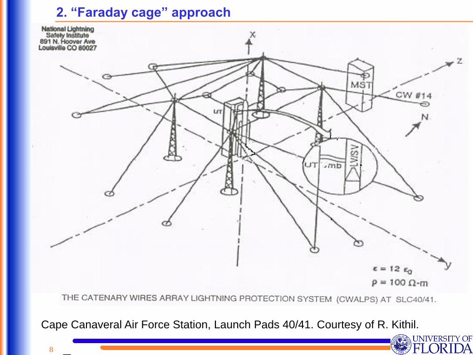
Cape Canaveral Air Force Station Launch Pads 4041 Courtesy of R Kithil
9
Cape Canaveral Air Force Station Launch Pad 41 Courtesy of R Kithil
2 ldquoFaraday cagerdquo approach
10
Illustration of capture surfaces of two towers and earthrsquos surface in the electrogeometrical
model (EGM) rs is the striking distance defined as the distance from the tip of the descending
leader to the object to be struck at the instant when an upward connecting leader is initiated
from this object Vertical arrows represent descending leaders assumed to be uniformly
distributed (Ng=const) above the capture surfaces Adapted from Bazelyan and Raizer (2000)
3 Placement of air terminals
rs
rs
rs
Capture surfaces
Ng=const
Electrogeometrical model (EGM)
11
3 Placement of air terminals
rs = 10 I065
m
where I is in kA
4
3
1
2
Striking distance rs versus return-stroke peak current I [curve 1 Golde (1945) curve 2 Wagner (1963)
curve 3 Love (1973) curve 4 Ruhling (1972) x theory of Davis (1962) estimates from two-
dimensional photographs by Eriksson (1978) estimates from three-dimensional photography by
Eriksson (1978) Adapted from Golde (1977) and Eriksson (1978)
I kA rs m
10 45
30 91
170 282
12
Scatter plot of impulse charge Q versus return-stroke
peak current I Note that both vertical and horizontal
scales are logarithmic The best fit to data I = 106 Q07
where Q is in coulombs and I is in kiloamperes was used
in deriving rs = 10 I065 Adapted from Berger (1972)
3 Placement of air terminals
Finding rs = f(I)
bull Assume critical average
electric field between the
leader tip and the strike
object at the time of
initiation of upward
connecting leader from the
object (200-600 kVm)
bull Use an empirical relation
between Q and I to find
rs = f(I)
bull Finding rs = f(Q)
bull Assume leader geometry
total leader charge Q and
distribution of this charge
along the channel
Q
10-1
100
101
102
100 101 102
I
I peak Q impulse
neg first strokes
n=89
I = 106 Q07
For Q = 5 C
I = 33 kA
13
3 Placement of air terminals
Illustration of the rolling-sphere method (RSM) The shaded area is that area into
which it is postulated lightning cannot enter Adapted from Szczerbinski (2000)
rs
rs
rs
rs = 46 m (150 ft)
(NFPA 780 2004)
corresponds to I = 101 kA
(95 of currents exceed this value)
Rolling-Sphere Method
14
Photograph of surface arcing associated with the second stroke (current peak I=30 kA)
of flash 9312 triggered at Fort McClellan Alabama (Rg=260 Ω) The lightning
channel is outside the field of view One of the surface arcs approached the right edge
of the photograph a distance of 10 m from the rocket launcher Adapted from Fisher
et al (1994) V= I x Rg=78 MV
4 Behavior of grounding systems under direct lightning strike conditions
15
5 Bonding Requirements
Illustration of safety distances in the soil (Dsoil) and in air (Dair) Adapted from
Kuzhekin et al (2003)
LPS down conductor
LPS grounding
system
Protected ObjectL
Buried Services
Wooden pole
LPS air terminal
Dair
Dsoil
Dsoil = I Zg Eb
If I = 60 kA Zg = 25 Ω and Eb= 300 kVm Dsoil = 5 m
Dair = 012Zg+01L
I = the lightning peak
current
Zg = the grounding
impedance
Eb = the breakdown
electric field in
the soil
Bond whenever you cannot adequately isolate
16
5 Bonding Requirements
Peak current I
kA 5 10 20 40 60 80 100 200
Percentage
exceeding
tabulated value
ΡI 100
99 95 76 34 15 78 45 08
Dsoil m (Zg = 25
Ω Eb = 300
kVm)
042 083 17 33 50 67 83 17
The IEEE peak current distribution given by equation (1) and corresponding values of Dsoil
given by equation (2)
(1) (2)PI = 1 + (I 31)26
1Dsoil = IZgEb m
17
5 Bonding Requirements
Bonding of external services near ground level Taken from Wiesinger and
Zischank (1995)
structure
clamp gap
information line
power linepipe
arrester
18
6 Non-conventional approaches to lightning protection
Early Streamer Emission (ESE) systems
Lightning struck point B (without air terminal) which was within the claimed protection radius of
30 m of the ESE air terminal at point A The distance between A and B is 18 m After the strike
the manufacturer installed an additional ESE Terminal at point B Taken from Chrzan and
Hartono (2003)
19
6 Non-conventional approaches to lightning protection
Lightning elimination systems
Evolution of lightning elimination
(dissipation) system claims
However
Multipoint corona systems (dissipation arrays) provide only local lightning protection They
reduce the number of lightning strikes to their own surface and the object components
directly covered by them The question of extending the protection area of such systems
still remains open (Aleksandrov et al 2005)
bull Corona current can discharge the
thundercloud
bull Corona charge can neutralize an
approaching lightning leader
bull Corona charge can suppress or
delay the formation of an upward
connecting leader from the
protected objectTaken from the European Power News February 2005
2020
Thank You
Lightning strike to the Washington Monument (169 m high) on July 1 2005
21
1 Franklin rod system
22
23
Surface arcing

2
2
Lightning Protection History and Modern Approaches
1 Franklin rod system
2 ldquoFaraday cagerdquo approach
3 Placement of air terminals
4 Behavior of grounding systems under direct lightning strike
conditions
5 Bonding Requirements
6 Non-conventional approaches to lightning protection
3
1 Franklin rod system (first described in 1753)
Lightning protection system for houses proposed (most likely by G Ch Lichtenberg) in
1778 Adapted from Wiesinger and Zischank (1995)
Air terminal
Down conductor
Ground terminal
4
1 Franklin rod system
Metallic roofs whose thickness is 48 mm (316 in) or greater do not require air
terminals (NFPA 780)
Air terminal
Down conductor
Ground terminal
Air terminal locations (UL 96A Fig 62 1998)
A= 20 feet (6 m) maximum
spacing for 10 inch (254
mm) air terminal height or
25 feet (76 m) maximum
spacing for 24 inch (610
mm) air terminal height
B= 2 feet (610 mm) maximum
spacing from corner roof
edge or ridge end
5
In 1876 James Clerk Maxwell
proposed that a gunpowder building
be completely enclosed with metal
of sufficient thickness forming what
is now referred to as a Faraday
cage
If lightning were to strike a metal-
enclosed building the current would
be constrained to the exterior of the
metal enclosure and it would not
even be necessary to ground this
enclosure In the later case the
lightning would merely produce an
arc from the enclosure to earth
The Faraday cage effect is provided
by all-metal cars and airplanes
Modern steel-frame buildings with
reinforcing metal bars in the
concrete foundation connected to
the building steel provide a good
approximation to a Faraday cage
The general principles of topological
shielding Adapted from Vance (1980)
2 ldquoFaraday cagerdquo approach
Zone 1
Zone 3
Zone 1
Zone 2
1
10
22 3
Zone 0
SPD = Surge Protective Device
6
2 ldquoFaraday cagerdquo approach
Lightning strike to a car with a live rabbit inside Courtesy of S Sumi
7
Video frame of a lightning strike to an aircraft on takeoff from the Kamatsu Air
Force Base Japan during winter Courtesy of Z I Kawasaki
2 ldquoFaraday cagerdquo approach
8
2 ldquoFaraday cagerdquo approach
Cape Canaveral Air Force Station Launch Pads 4041 Courtesy of R Kithil
9
Cape Canaveral Air Force Station Launch Pad 41 Courtesy of R Kithil
2 ldquoFaraday cagerdquo approach
10
Illustration of capture surfaces of two towers and earthrsquos surface in the electrogeometrical
model (EGM) rs is the striking distance defined as the distance from the tip of the descending
leader to the object to be struck at the instant when an upward connecting leader is initiated
from this object Vertical arrows represent descending leaders assumed to be uniformly
distributed (Ng=const) above the capture surfaces Adapted from Bazelyan and Raizer (2000)
3 Placement of air terminals
rs
rs
rs
Capture surfaces
Ng=const
Electrogeometrical model (EGM)
11
3 Placement of air terminals
rs = 10 I065
m
where I is in kA
4
3
1
2
Striking distance rs versus return-stroke peak current I [curve 1 Golde (1945) curve 2 Wagner (1963)
curve 3 Love (1973) curve 4 Ruhling (1972) x theory of Davis (1962) estimates from two-
dimensional photographs by Eriksson (1978) estimates from three-dimensional photography by
Eriksson (1978) Adapted from Golde (1977) and Eriksson (1978)
I kA rs m
10 45
30 91
170 282
12
Scatter plot of impulse charge Q versus return-stroke
peak current I Note that both vertical and horizontal
scales are logarithmic The best fit to data I = 106 Q07
where Q is in coulombs and I is in kiloamperes was used
in deriving rs = 10 I065 Adapted from Berger (1972)
3 Placement of air terminals
Finding rs = f(I)
bull Assume critical average
electric field between the
leader tip and the strike
object at the time of
initiation of upward
connecting leader from the
object (200-600 kVm)
bull Use an empirical relation
between Q and I to find
rs = f(I)
bull Finding rs = f(Q)
bull Assume leader geometry
total leader charge Q and
distribution of this charge
along the channel
Q
10-1
100
101
102
100 101 102
I
I peak Q impulse
neg first strokes
n=89
I = 106 Q07
For Q = 5 C
I = 33 kA
13
3 Placement of air terminals
Illustration of the rolling-sphere method (RSM) The shaded area is that area into
which it is postulated lightning cannot enter Adapted from Szczerbinski (2000)
rs
rs
rs
rs = 46 m (150 ft)
(NFPA 780 2004)
corresponds to I = 101 kA
(95 of currents exceed this value)
Rolling-Sphere Method
14
Photograph of surface arcing associated with the second stroke (current peak I=30 kA)
of flash 9312 triggered at Fort McClellan Alabama (Rg=260 Ω) The lightning
channel is outside the field of view One of the surface arcs approached the right edge
of the photograph a distance of 10 m from the rocket launcher Adapted from Fisher
et al (1994) V= I x Rg=78 MV
4 Behavior of grounding systems under direct lightning strike conditions
15
5 Bonding Requirements
Illustration of safety distances in the soil (Dsoil) and in air (Dair) Adapted from
Kuzhekin et al (2003)
LPS down conductor
LPS grounding
system
Protected ObjectL
Buried Services
Wooden pole
LPS air terminal
Dair
Dsoil
Dsoil = I Zg Eb
If I = 60 kA Zg = 25 Ω and Eb= 300 kVm Dsoil = 5 m
Dair = 012Zg+01L
I = the lightning peak
current
Zg = the grounding
impedance
Eb = the breakdown
electric field in
the soil
Bond whenever you cannot adequately isolate
16
5 Bonding Requirements
Peak current I
kA 5 10 20 40 60 80 100 200
Percentage
exceeding
tabulated value
ΡI 100
99 95 76 34 15 78 45 08
Dsoil m (Zg = 25
Ω Eb = 300
kVm)
042 083 17 33 50 67 83 17
The IEEE peak current distribution given by equation (1) and corresponding values of Dsoil
given by equation (2)
(1) (2)PI = 1 + (I 31)26
1Dsoil = IZgEb m
17
5 Bonding Requirements
Bonding of external services near ground level Taken from Wiesinger and
Zischank (1995)
structure
clamp gap
information line
power linepipe
arrester
18
6 Non-conventional approaches to lightning protection
Early Streamer Emission (ESE) systems
Lightning struck point B (without air terminal) which was within the claimed protection radius of
30 m of the ESE air terminal at point A The distance between A and B is 18 m After the strike
the manufacturer installed an additional ESE Terminal at point B Taken from Chrzan and
Hartono (2003)
19
6 Non-conventional approaches to lightning protection
Lightning elimination systems
Evolution of lightning elimination
(dissipation) system claims
However
Multipoint corona systems (dissipation arrays) provide only local lightning protection They
reduce the number of lightning strikes to their own surface and the object components
directly covered by them The question of extending the protection area of such systems
still remains open (Aleksandrov et al 2005)
bull Corona current can discharge the
thundercloud
bull Corona charge can neutralize an
approaching lightning leader
bull Corona charge can suppress or
delay the formation of an upward
connecting leader from the
protected objectTaken from the European Power News February 2005
2020
Thank You
Lightning strike to the Washington Monument (169 m high) on July 1 2005
21
1 Franklin rod system
22
23
Surface arcing

3
1 Franklin rod system (first described in 1753)
Lightning protection system for houses proposed (most likely by G Ch Lichtenberg) in
1778 Adapted from Wiesinger and Zischank (1995)
Air terminal
Down conductor
Ground terminal
4
1 Franklin rod system
Metallic roofs whose thickness is 48 mm (316 in) or greater do not require air
terminals (NFPA 780)
Air terminal
Down conductor
Ground terminal
Air terminal locations (UL 96A Fig 62 1998)
A= 20 feet (6 m) maximum
spacing for 10 inch (254
mm) air terminal height or
25 feet (76 m) maximum
spacing for 24 inch (610
mm) air terminal height
B= 2 feet (610 mm) maximum
spacing from corner roof
edge or ridge end
5
In 1876 James Clerk Maxwell
proposed that a gunpowder building
be completely enclosed with metal
of sufficient thickness forming what
is now referred to as a Faraday
cage
If lightning were to strike a metal-
enclosed building the current would
be constrained to the exterior of the
metal enclosure and it would not
even be necessary to ground this
enclosure In the later case the
lightning would merely produce an
arc from the enclosure to earth
The Faraday cage effect is provided
by all-metal cars and airplanes
Modern steel-frame buildings with
reinforcing metal bars in the
concrete foundation connected to
the building steel provide a good
approximation to a Faraday cage
The general principles of topological
shielding Adapted from Vance (1980)
2 ldquoFaraday cagerdquo approach
Zone 1
Zone 3
Zone 1
Zone 2
1
10
22 3
Zone 0
SPD = Surge Protective Device
6
2 ldquoFaraday cagerdquo approach
Lightning strike to a car with a live rabbit inside Courtesy of S Sumi
7
Video frame of a lightning strike to an aircraft on takeoff from the Kamatsu Air
Force Base Japan during winter Courtesy of Z I Kawasaki
2 ldquoFaraday cagerdquo approach
8
2 ldquoFaraday cagerdquo approach
Cape Canaveral Air Force Station Launch Pads 4041 Courtesy of R Kithil
9
Cape Canaveral Air Force Station Launch Pad 41 Courtesy of R Kithil
2 ldquoFaraday cagerdquo approach
10
Illustration of capture surfaces of two towers and earthrsquos surface in the electrogeometrical
model (EGM) rs is the striking distance defined as the distance from the tip of the descending
leader to the object to be struck at the instant when an upward connecting leader is initiated
from this object Vertical arrows represent descending leaders assumed to be uniformly
distributed (Ng=const) above the capture surfaces Adapted from Bazelyan and Raizer (2000)
3 Placement of air terminals
rs
rs
rs
Capture surfaces
Ng=const
Electrogeometrical model (EGM)
11
3 Placement of air terminals
rs = 10 I065
m
where I is in kA
4
3
1
2
Striking distance rs versus return-stroke peak current I [curve 1 Golde (1945) curve 2 Wagner (1963)
curve 3 Love (1973) curve 4 Ruhling (1972) x theory of Davis (1962) estimates from two-
dimensional photographs by Eriksson (1978) estimates from three-dimensional photography by
Eriksson (1978) Adapted from Golde (1977) and Eriksson (1978)
I kA rs m
10 45
30 91
170 282
12
Scatter plot of impulse charge Q versus return-stroke
peak current I Note that both vertical and horizontal
scales are logarithmic The best fit to data I = 106 Q07
where Q is in coulombs and I is in kiloamperes was used
in deriving rs = 10 I065 Adapted from Berger (1972)
3 Placement of air terminals
Finding rs = f(I)
bull Assume critical average
electric field between the
leader tip and the strike
object at the time of
initiation of upward
connecting leader from the
object (200-600 kVm)
bull Use an empirical relation
between Q and I to find
rs = f(I)
bull Finding rs = f(Q)
bull Assume leader geometry
total leader charge Q and
distribution of this charge
along the channel
Q
10-1
100
101
102
100 101 102
I
I peak Q impulse
neg first strokes
n=89
I = 106 Q07
For Q = 5 C
I = 33 kA
13
3 Placement of air terminals
Illustration of the rolling-sphere method (RSM) The shaded area is that area into
which it is postulated lightning cannot enter Adapted from Szczerbinski (2000)
rs
rs
rs
rs = 46 m (150 ft)
(NFPA 780 2004)
corresponds to I = 101 kA
(95 of currents exceed this value)
Rolling-Sphere Method
14
Photograph of surface arcing associated with the second stroke (current peak I=30 kA)
of flash 9312 triggered at Fort McClellan Alabama (Rg=260 Ω) The lightning
channel is outside the field of view One of the surface arcs approached the right edge
of the photograph a distance of 10 m from the rocket launcher Adapted from Fisher
et al (1994) V= I x Rg=78 MV
4 Behavior of grounding systems under direct lightning strike conditions
15
5 Bonding Requirements
Illustration of safety distances in the soil (Dsoil) and in air (Dair) Adapted from
Kuzhekin et al (2003)
LPS down conductor
LPS grounding
system
Protected ObjectL
Buried Services
Wooden pole
LPS air terminal
Dair
Dsoil
Dsoil = I Zg Eb
If I = 60 kA Zg = 25 Ω and Eb= 300 kVm Dsoil = 5 m
Dair = 012Zg+01L
I = the lightning peak
current
Zg = the grounding
impedance
Eb = the breakdown
electric field in
the soil
Bond whenever you cannot adequately isolate
16
5 Bonding Requirements
Peak current I
kA 5 10 20 40 60 80 100 200
Percentage
exceeding
tabulated value
ΡI 100
99 95 76 34 15 78 45 08
Dsoil m (Zg = 25
Ω Eb = 300
kVm)
042 083 17 33 50 67 83 17
The IEEE peak current distribution given by equation (1) and corresponding values of Dsoil
given by equation (2)
(1) (2)PI = 1 + (I 31)26
1Dsoil = IZgEb m
17
5 Bonding Requirements
Bonding of external services near ground level Taken from Wiesinger and
Zischank (1995)
structure
clamp gap
information line
power linepipe
arrester
18
6 Non-conventional approaches to lightning protection
Early Streamer Emission (ESE) systems
Lightning struck point B (without air terminal) which was within the claimed protection radius of
30 m of the ESE air terminal at point A The distance between A and B is 18 m After the strike
the manufacturer installed an additional ESE Terminal at point B Taken from Chrzan and
Hartono (2003)
19
6 Non-conventional approaches to lightning protection
Lightning elimination systems
Evolution of lightning elimination
(dissipation) system claims
However
Multipoint corona systems (dissipation arrays) provide only local lightning protection They
reduce the number of lightning strikes to their own surface and the object components
directly covered by them The question of extending the protection area of such systems
still remains open (Aleksandrov et al 2005)
bull Corona current can discharge the
thundercloud
bull Corona charge can neutralize an
approaching lightning leader
bull Corona charge can suppress or
delay the formation of an upward
connecting leader from the
protected objectTaken from the European Power News February 2005
2020
Thank You
Lightning strike to the Washington Monument (169 m high) on July 1 2005
21
1 Franklin rod system
22
23
Surface arcing

4
1 Franklin rod system
Metallic roofs whose thickness is 48 mm (316 in) or greater do not require air
terminals (NFPA 780)
Air terminal
Down conductor
Ground terminal
Air terminal locations (UL 96A Fig 62 1998)
A= 20 feet (6 m) maximum
spacing for 10 inch (254
mm) air terminal height or
25 feet (76 m) maximum
spacing for 24 inch (610
mm) air terminal height
B= 2 feet (610 mm) maximum
spacing from corner roof
edge or ridge end
5
In 1876 James Clerk Maxwell
proposed that a gunpowder building
be completely enclosed with metal
of sufficient thickness forming what
is now referred to as a Faraday
cage
If lightning were to strike a metal-
enclosed building the current would
be constrained to the exterior of the
metal enclosure and it would not
even be necessary to ground this
enclosure In the later case the
lightning would merely produce an
arc from the enclosure to earth
The Faraday cage effect is provided
by all-metal cars and airplanes
Modern steel-frame buildings with
reinforcing metal bars in the
concrete foundation connected to
the building steel provide a good
approximation to a Faraday cage
The general principles of topological
shielding Adapted from Vance (1980)
2 ldquoFaraday cagerdquo approach
Zone 1
Zone 3
Zone 1
Zone 2
1
10
22 3
Zone 0
SPD = Surge Protective Device
6
2 ldquoFaraday cagerdquo approach
Lightning strike to a car with a live rabbit inside Courtesy of S Sumi
7
Video frame of a lightning strike to an aircraft on takeoff from the Kamatsu Air
Force Base Japan during winter Courtesy of Z I Kawasaki
2 ldquoFaraday cagerdquo approach
8
2 ldquoFaraday cagerdquo approach
Cape Canaveral Air Force Station Launch Pads 4041 Courtesy of R Kithil
9
Cape Canaveral Air Force Station Launch Pad 41 Courtesy of R Kithil
2 ldquoFaraday cagerdquo approach
10
Illustration of capture surfaces of two towers and earthrsquos surface in the electrogeometrical
model (EGM) rs is the striking distance defined as the distance from the tip of the descending
leader to the object to be struck at the instant when an upward connecting leader is initiated
from this object Vertical arrows represent descending leaders assumed to be uniformly
distributed (Ng=const) above the capture surfaces Adapted from Bazelyan and Raizer (2000)
3 Placement of air terminals
rs
rs
rs
Capture surfaces
Ng=const
Electrogeometrical model (EGM)
11
3 Placement of air terminals
rs = 10 I065
m
where I is in kA
4
3
1
2
Striking distance rs versus return-stroke peak current I [curve 1 Golde (1945) curve 2 Wagner (1963)
curve 3 Love (1973) curve 4 Ruhling (1972) x theory of Davis (1962) estimates from two-
dimensional photographs by Eriksson (1978) estimates from three-dimensional photography by
Eriksson (1978) Adapted from Golde (1977) and Eriksson (1978)
I kA rs m
10 45
30 91
170 282
12
Scatter plot of impulse charge Q versus return-stroke
peak current I Note that both vertical and horizontal
scales are logarithmic The best fit to data I = 106 Q07
where Q is in coulombs and I is in kiloamperes was used
in deriving rs = 10 I065 Adapted from Berger (1972)
3 Placement of air terminals
Finding rs = f(I)
bull Assume critical average
electric field between the
leader tip and the strike
object at the time of
initiation of upward
connecting leader from the
object (200-600 kVm)
bull Use an empirical relation
between Q and I to find
rs = f(I)
bull Finding rs = f(Q)
bull Assume leader geometry
total leader charge Q and
distribution of this charge
along the channel
Q
10-1
100
101
102
100 101 102
I
I peak Q impulse
neg first strokes
n=89
I = 106 Q07
For Q = 5 C
I = 33 kA
13
3 Placement of air terminals
Illustration of the rolling-sphere method (RSM) The shaded area is that area into
which it is postulated lightning cannot enter Adapted from Szczerbinski (2000)
rs
rs
rs
rs = 46 m (150 ft)
(NFPA 780 2004)
corresponds to I = 101 kA
(95 of currents exceed this value)
Rolling-Sphere Method
14
Photograph of surface arcing associated with the second stroke (current peak I=30 kA)
of flash 9312 triggered at Fort McClellan Alabama (Rg=260 Ω) The lightning
channel is outside the field of view One of the surface arcs approached the right edge
of the photograph a distance of 10 m from the rocket launcher Adapted from Fisher
et al (1994) V= I x Rg=78 MV
4 Behavior of grounding systems under direct lightning strike conditions
15
5 Bonding Requirements
Illustration of safety distances in the soil (Dsoil) and in air (Dair) Adapted from
Kuzhekin et al (2003)
LPS down conductor
LPS grounding
system
Protected ObjectL
Buried Services
Wooden pole
LPS air terminal
Dair
Dsoil
Dsoil = I Zg Eb
If I = 60 kA Zg = 25 Ω and Eb= 300 kVm Dsoil = 5 m
Dair = 012Zg+01L
I = the lightning peak
current
Zg = the grounding
impedance
Eb = the breakdown
electric field in
the soil
Bond whenever you cannot adequately isolate
16
5 Bonding Requirements
Peak current I
kA 5 10 20 40 60 80 100 200
Percentage
exceeding
tabulated value
ΡI 100
99 95 76 34 15 78 45 08
Dsoil m (Zg = 25
Ω Eb = 300
kVm)
042 083 17 33 50 67 83 17
The IEEE peak current distribution given by equation (1) and corresponding values of Dsoil
given by equation (2)
(1) (2)PI = 1 + (I 31)26
1Dsoil = IZgEb m
17
5 Bonding Requirements
Bonding of external services near ground level Taken from Wiesinger and
Zischank (1995)
structure
clamp gap
information line
power linepipe
arrester
18
6 Non-conventional approaches to lightning protection
Early Streamer Emission (ESE) systems
Lightning struck point B (without air terminal) which was within the claimed protection radius of
30 m of the ESE air terminal at point A The distance between A and B is 18 m After the strike
the manufacturer installed an additional ESE Terminal at point B Taken from Chrzan and
Hartono (2003)
19
6 Non-conventional approaches to lightning protection
Lightning elimination systems
Evolution of lightning elimination
(dissipation) system claims
However
Multipoint corona systems (dissipation arrays) provide only local lightning protection They
reduce the number of lightning strikes to their own surface and the object components
directly covered by them The question of extending the protection area of such systems
still remains open (Aleksandrov et al 2005)
bull Corona current can discharge the
thundercloud
bull Corona charge can neutralize an
approaching lightning leader
bull Corona charge can suppress or
delay the formation of an upward
connecting leader from the
protected objectTaken from the European Power News February 2005
2020
Thank You
Lightning strike to the Washington Monument (169 m high) on July 1 2005
21
1 Franklin rod system
22
23
Surface arcing
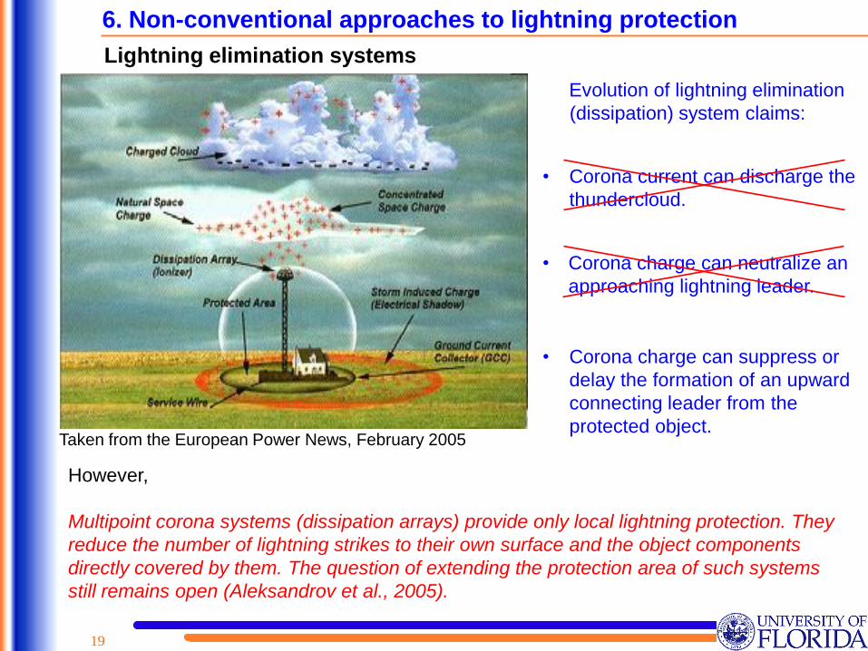

2020
Thank You
Lightning strike to the Washington Monument (169 m high) on July 1 2005
21
1 Franklin rod system
22
23
Surface arcing

21
1 Franklin rod system
22
23
Surface arcing

22
23
Surface arcing

23
Surface arcing