lighting management solutions - doc...
TRANSCRIPT

Lighting Management solutionsBest practice guide for office buildings
PUTTING A STOP TO ENERGY WASTE

INTRODUCTION
1Lighting control Best Practice
Guide for Office Buildings
2Guide roadmap
4Small conference room
13Large conference room
21Private offices
25Large private Office
29Kitchen
33Open Office
41Cubicle workstation
45Hallway/Elevator
53Lobby
57Restroom
61Exterior
65Centralized management
Table of contents

1LI
GHTI
NG M
ANAG
EMEN
T SO
LUTI
ONS
|BE
STPR
ACTI
CEGU
IDE
FOR
OFFI
CEBU
ILDI
NGS
LIGHTING CONTROL BEST PRACTICEGUIDE FOR OFFICE BUILDINGSWith years of experience developing and producing lightingcontrols, Legrand has helped many organizations identifyand implement energy saving lighting control systems. Whileevery facility offers unique challenges, there are optimalsolutions available that meet the needs of building owners aswell as facility managers and occupants.
Legrand offers a comprehensive range of lighting controlproducts encompassing several product lines: occupancysensors, actuators, daylighting controls, and productsfor integrated control among multiple building systems.With these product resources and unsurpassed technicalexpertise, Legrand ensures that lighting professionals choosethe right combination of products to achieve the control needsof today’s office buildings.
This Best Practice publication focuses on design,specification, and installation guidance for lightingmanagement in commercial office buildings. It featuresapplications that illustrate the best control practices for avariety of spaces. Each best practice considers the space usecharacteristics, occupant needs, lighting operation costs,energy savings and compliance with the requirements of mostnational standards.
Each Best Practice includes:
For each of the examples given in this document, there is arecommended configuration method:- Plug n'go: products automatically self-configure whenpowered up.- Push n' learn: configuration is done by hand (no toolrequired) by pressing the learn key on each product.- Software suite: software-based configuration to meetfunctionally more advanced requirements.
The best practice for open office areas is dependent upon thebuilding size and the owner’s needs. For small, single floor officebuildings or an open office area in a leased space, occupancysensors are a good strategy. For larger, owner occupiedbuildings, or multi-floor tenants, scheduling using actuators isrecommended because one time clock can control lighting onmultiple floors. Combining scheduling and occupancy sensorscontrol offers the benefit and convenience of keeping lightingon during normal hours of operation, yet after hours allowsoccupancy based control for additional energy savings.
2
LIGH
TING
MAN
AGEM
ENT
SOLU
TION
S|
BEST
PRAC
TICE
GUID
EFO
ROF
FICE
BUIL
DING
S
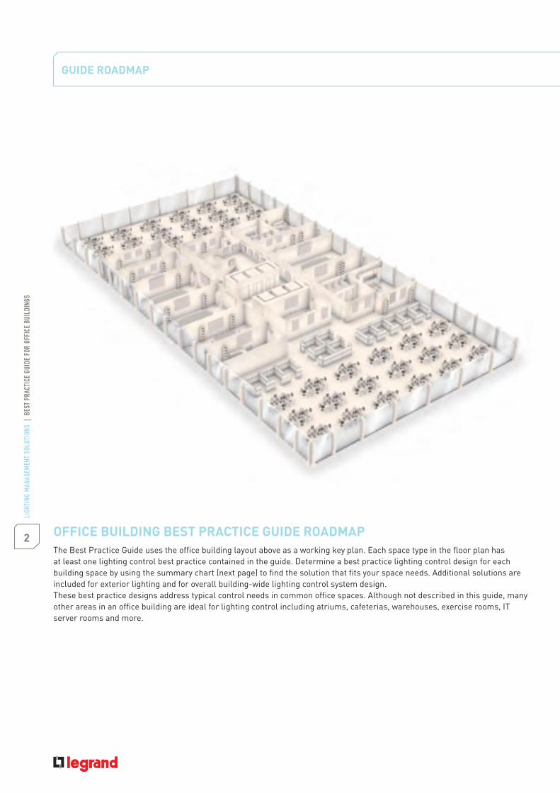
OFFICE BUILDING BEST PRACTICE GUIDE ROADMAPThe Best Practice Guide uses the office building layout above as a working key plan. Each space type in the floor plan has
building space by using the summary chart (next page) to find the solution that fits your space needs. Additional solutions areincluded for exterior lighting and for overall building-wide lighting control system design.These best practice designs address typical control needs in common office spaces. Although not described in this guide, manyother areas in an office building are ideal for lighting control including atriums, cafeterias, warehouses, exercise rooms, ITserver rooms and more.
GUIDE ROADMAP

3LI
GHTI
NG M
ANAG
EMEN
T SO
LUTI
ONS
|BE
STPR
ACTI
CEGU
IDE
FOR
OFFI
CEBU
ILDI
NGS
Space/application practice Detection technology Control strategy Daylighting Control Scenarios Type of loads Motors control Page
Small conferenceroom (1) PIR Vacancy
sensing yes ON/OFF no no 5
Small conferenceroom (2)
Occupancysensing no no
1-10 VfluorescentEco halogen
yes 9
Large conferenceroom (1)
Vacancysensing yes no 1-10 V
fluorescent no 13
Large conferenceroom (2)
Vacancysensing yes ON/OFF
dimming yes1-10 V
fluorescentEco halogen
yes 17
Private offices PIR Vacancysensing yes no 1-10 V
fluorescent no 21
Large private office Vacancysensing yes ON/OFF
dimming no 1-10 Vfluorescent yes 25
Kitchen PIR Occupancysensing no ON/OFF no Fluorescent yes 29
Open office (1) Vacancysensing yes no no 33
Open office (2) N/A N/A Timescheduling yes no no 37
Cubicle Vacancysensing no ON/OFF no Fluorescent no 41
Hallway elevator (1) Ultrasonic Occupancysensing no ON/OFF no Fluorescent no 45
Hallway elevator (2) Ultrasonic Timescheduling no ON/OFF no Fluorescent no 49
Lobby PIR & Occupancysensing yes yes Halogen no 53
Restroom Ultrasonic Occupancysensing no ON/OFF no Fluorescent yes 57
Exterior PIR Occupancysensing yes ON/OFF no fluorescent no 61
SUMMARY OF BEST PRACTICES FOR LIGHTING CONTROL IN OFFICE BUILDINGS

4
SMALL CONFERENCE ROOM

5LI
GHTI
NG M
ANAG
EMEN
T SO
LUTI
ONS
|BE
STPR
ACTI
CEGU
IDE
FOR
OFFI
CEBU
ILDI
NGS
CONTROL NEEDS1. Manual lighting control with automatic OFF based on occupancy2. Manual ON by push-buttons
LIGHTING
APPLICATION DESCRIPTIONSpace use Meetings of small groups (e.g. project team)
2
Ceiling height 2.50 mWindows Along one wall providing view to exterior provided
with horizontal blinds provided
SOLUTION1. Ceiling-mounted PIR sensor2. Room controller 2 outputs3. Push-buttons
- Vacancy sensing- ON/OFF control LED- Daylighting

LIGH
TING
MAN
AGEM
ENT
SOLU
TION
S|
BEST
PRAC
TICE
GUID
EFO
ROF
FICE
BUIL
DING
S
SMALL CONFERENCE ROOM
Vacancy sensing, ON/OFF control LED, daylighting
LIGHTING PLAN
DESIGN SOLUTION DESCRIPTION
square version or Cat.No 573 050 round version (Arteor) are used to turn ON/OFF manually the central light circuit (circuit )and the white board lights (circuit ).The PIR BUS sensor Cat.No 488 20 is mounted in the centre of the conference room for a full view. It turns all lights off whenthe room is not occupied. It turns the central lights OFF (circuit ) when the lux set point is reached.The room controller Cat.No 488 50 is fixed on the cable tray in the false ceiling.
6
7LI
GHTI
NG M
ANAG
EMEN
T SO
LUTI
ONS
|BE
STPR
ACTI
CEGU
IDE
FOR
OFFI
CEBU
ILDI
NGS
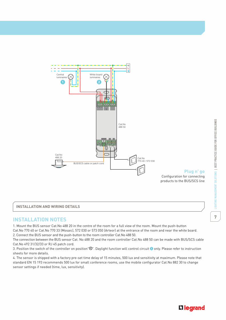
INSTALLATION NOTES1. Mount the BUS sensor Cat.No 488 20 in the centre of the room for a full view of the room. Mount the push-buttonCat.No 770 40 or Cat.No 770 33 (Mosaic), 572 030 or 573 050 (Arteor) at the entrance of the room and near the white board.2. Connect the BUS sensor and the push-button to the room controller Cat.No 488 50.The connection between the BUS sensor Cat. No 488 20 and the room controller Cat.No 488 50 can be made with BUS/SCS cableCat.No 492 31/32/33 or RJ 45 patch cord.3. Position the switch of the controller on position" only. Please refer to instructionsheets for more details.4. The sensor is shipped with a factory pre-set time delay of 15 minutes, 500 lux and sensitivity at maximum. Please note thatstandard EN 15 193 recommends 500 lux for small conference rooms, use the mobile configurator Cat.No 882 30 to changesensor settings if needed (time, lux, sensitivity).
INSTALLATION AND WIRING DETAILS
1
SENSOR
NO NCC
White boardluminaires
Centralluminaires
Cat.No488 20
Cat.No488 50
Cat.No770 40 / 572 030
BUS/SCS cable or patch cord
Plug n' goConfiguration for connecting
products to the BUS/SCS line

8
LIGH
TING
MAN
AGEM
ENT
SOLU
TION
S|
BEST
PRAC
TICE
GUID
EFO
ROF
FICE
BUIL
DING
S
1st option
Cat.Nos Quantity Description
488 50 1 Room controller 2 outputs 16 A
488 20 1 Ceiling-mounted PIR BUS sensor 360 °
770 40 2 Push-button - Mosaic
572 030 2 Push-button square version Arteor
573 050 2 Push-button round version Arteor
- Vacancy sensing- ON/OFF control LED- Daylighting
2nd option
Cat.Nos Quantity Description
488 41 1 BUS/SCS lighting room controllerON/OFF 2 outputs 16 A
488 20 1 Ceiling-mounted PIR BUS sensor 360 °
784 75 2 BUS lighting control unit1-way - Mosaic
573 987 2 BUS lighting control unit - Arteor
SMALL CONFERENCE ROOM
EQUIPMENT SCHEDULELOCAL MANAGEMENT
EQUIPMENT SCHEDULECENTRALIZED MANAGEMENT
Please refer to page 65 for more information (Centralized management)
488 20
488 20 784 75
770 40488 50
488 41

9LI
GHTI
NG M
ANAG
EMEN
T SO
LUTI
ONS
|BE
STPR
ACTI
CEGU
IDE
FOR
OFFI
CEBU
ILDI
NGS
- Occupancy sensing- Dimming control fluorescent1-10 V- ON/OFF control ECO halogen- Automation control
CONTROL NEEDS1. Automatic lighting control based on occupancy2. Manual control over the 2 outputs (halogen lights + screen)3. Occupancy-based control of fan system4. Fully automatic-OFF
LIGHTINGCeiling-mounted T5 luminaires, 1-10 V ballast
APPLICATION DESCRIPTIONSpace use Meetings of small groups (e.g. project team)
2
Ceiling height 2.50 mWindows None
SOLUTION1. Wall-mounted technology BUS sensor2. BUS/SCS room controller 2 outputs for lights (1 for halogen &
1 for fluorescent) + 2 outputs for automation (1 for the fan + 1 forthe screen)
3. Remote control
10
LIGH
TING
MAN
AGEM
ENT
SOLU
TION
S|
BEST
PRAC
TICE
GUID
EFO
ROF
FICE
BUIL
DING
S
SMALL CONFERENCE ROOM
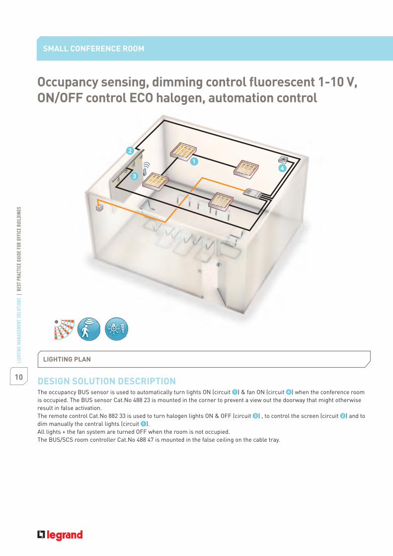
DESIGN SOLUTION DESCRIPTIONThe occupancy BUS sensor is used to automatically turn lights ON (circuit ) & fan ON (circuit ) when the conference roomis occupied. The BUS sensor Cat.No 488 23 is mounted in the corner to prevent a view out the doorway that might otherwiseresult in false activation.The remote control Cat.No 882 33 is used to turn halogen lights ON & OFF (circuit ) , to control the screen (circuit ) and todim manually the central lights (circuit ).All lights + the fan system are turned OFF when the room is not occupied.The BUS/SCS room controller Cat.No 488 47 is mounted in the false ceiling on the cable tray.
Occupancy sensing, dimming control fluorescent 1-10 V,ON/OFF control ECO halogen, automation control
LIGHTING PLAN
11LI
GHTI
NG M
ANAG
EMEN
T SO
LUTI
ONS
|BE
STPR
ACTI
CEGU
IDE
FOR
OFFI
CEBU
ILDI
NGS
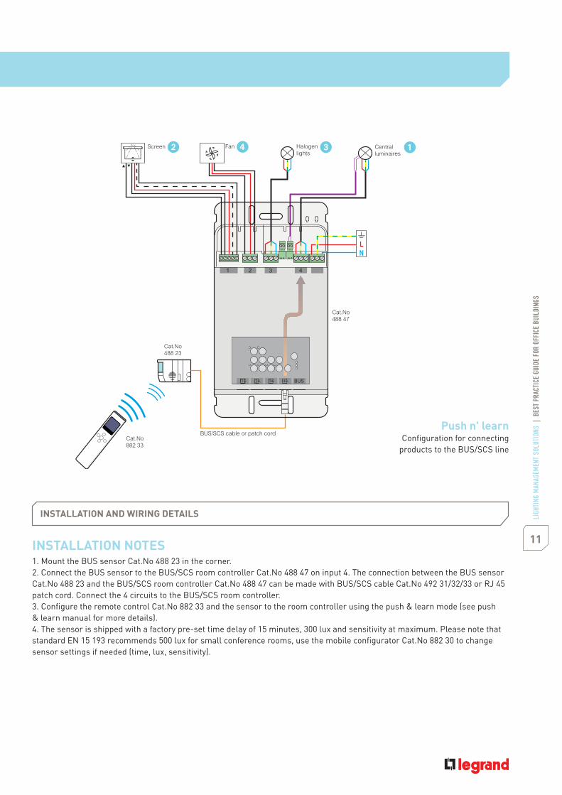
INSTALLATION NOTES1. Mount the BUS sensor Cat.No 488 23 in the corner.2. Connect the BUS sensor to the BUS/SCS room controller Cat.No 488 47 on input 4. The connection between the BUS sensorCat.No 488 23 and the BUS/SCS room controller Cat.No 488 47 can be made with BUS/SCS cable Cat.No 492 31/32/33 or RJ 45patch cord. Connect the 4 circuits to the BUS/SCS room controller.3. Configure the remote control Cat.No 882 33 and the sensor to the room controller using the push & learn mode (see push& learn manual for more details).4. The sensor is shipped with a factory pre-set time delay of 15 minutes, 300 lux and sensitivity at maximum. Please note thatstandard EN 15 193 recommends 500 lux for small conference rooms, use the mobile configurator Cat.No 882 30 to changesensor settings if needed (time, lux, sensitivity).
INSTALLATION AND WIRING DETAILS
Halogenlights
Screen Centralluminaires
Cat.No488 23
Cat.No882 33
BUS/SCS cable or patch cord
Cat.No488 47
Fan
Push n' learnConfiguration for connecting
products to the BUS/SCS line

12
LIGH
TING
MAN
AGEM
ENT
SOLU
TION
S|
BEST
PRAC
TICE
GUID
EFO
ROF
FICE
BUIL
DING
S
Cat.Nos Quantity Description
488 47 1BUS/SCS room controller 2 outputsON/OFF or 1-10 V, 2 outputsfor blinds or fans
488 23 1 BUS sensor 180 °
882 33 1 IR remote control
OPTIONTo maximise comfort a 4 scenarios control can be added.
- Occupancy sensing- Dimming control fluorescent 1-10 V- ON/OFF control ECO halogen- Automation control
SMALL CONFERENCE ROOM
EQUIPMENT SCHEDULELOCAL MANAGEMENT & CENTRALIZED MANAGEMENT
Please refer to page 65 for more information (Centralized management)
488 47 488 23 882 33

13LI
GHTI
NG M
ANAG
EMEN
T SO
LUTI
ONS
|BE
STPR
ACTI
CEGU
IDE
FOR
OFFI
CEBU
ILDI
NGS
CONTROL NEEDS1. Turn lights manually ON and automatically OFF based on occupancy2. Manual override with ON/OFF and dimming cap3. Automatic dimming of lights according to daylight measurement
LIGHTINGCeiling-mounted luminaires using T5 , 1-10 V electronic ballasts
APPLICATION DESCRIPTIONSpace use Meetings, presentations (e.g. project team)
2
Ceiling height 2.50 mWindows Along one wall providing view to exterior
SOLUTION1.2. BUS/SCS room controller 4 outputs for 1-10 V ballasts3. Remote control4. BUS push-button
- Vacancy sensing- Dimming control fluorescent
1-10 V- ON/OFF control LEDs- Daylighting
LARGE CONFERENCE ROOM
14
LIGH
TING
MAN
AGEM
ENT
SOLU
TION
S|
BEST
PRAC
TICE
GUID
EFO
ROF
FICE
BUIL
DING
S
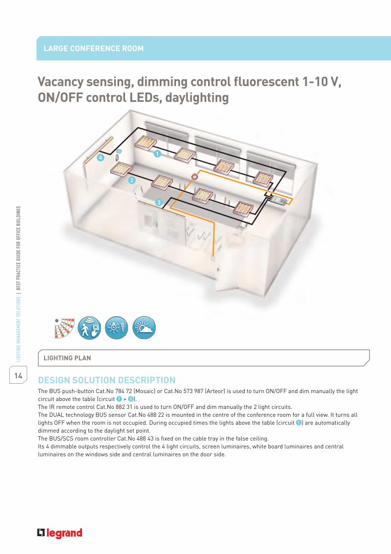
DESIGN SOLUTION DESCRIPTIONThe BUS push-button Cat.No 784 72 (Mosaic) or Cat.No 573 987 (Arteor) is used to turn ON/OFF and dim manually the lightcircuit above the table (circuit + ).The IR remote control Cat.No 882 31 is used to turn ON/OFF and dim manually the 2 light circuits.The technology BUS sensor Cat.No 488 22 is mounted in the centre of the conference room for a full view. It turns all
) are automaticallydimmed according to the daylight set point.The BUS/SCS room controller Cat.No 488 43 is fixed on the cable tray in the false ceiling.Its 4 dimmable outputs respectively control the 4 light circuits, screen luminaires, white board luminaires and centralluminaires on the windows side and central luminaires on the door side.
LARGE CONFERENCE ROOM
Vacancy sensing, dimming control fluorescent 1-10 V,ON/OFF control LEDs, daylighting
LIGHTING PLAN

15LI
GHTI
NG M
ANAG
EMEN
T SO
LUTI
ONS
|BE
STPR
ACTI
CEGU
IDE
FOR
OFFI
CEBU
ILDI
NGS
1 2 3 4
Screenluminaires
Centralluminaires
White boardluminaires
Centralluminaires
Cat.Nos784 72 / 573 987 Cat.No
488 22
BUS/SCS cableor patch cord
Cat.No882 31
Cat.No488 43
INSTALLATION NOTES1. Mount the BUS sensor Cat.No 488 22 in the centre of the room for a full view of the room. Mount the SCS push-buttonCat.No 784 72 (Mosaic) or Cat.No 573 987 (Arteor) at the entrance to the room.2. Connect the BUS sensor to the BUS/SCS room controller Cat.No 488 43. The connection between the BUS sensor Cat.No 488 22and the BUS/SCS room controller Cat.No 488 23 can be made with BUS/SCS cable Cat.No 492 31/32/33 or RJ 45 patch cord.They are connected to the same input (No 3) as they control the same output (circuit ). Connect the 4 circuits to theBUS/SCS room controller.3. Configure the remote control Cat.No 882 31, the BUS sensor and the BUS push-button to the appropriate outputs of theBUS/SCS room controller.Please refer to push & learn manual for more details.4. The sensor is shipped with a factory pre-set time delay of 15 minutes, 500 lux and sensitivity at maximum. Please note thatstandard EN 15 193 recommends 500 lux for large conference rooms, use the mobile configurator Cat.No 882 30 to changesensor settings if needed (time, lux, sensitivity).
INSTALLATION AND WIRING DETAILS
Push n' learnConfiguration for connecting
products to the BUS/SCS line

16
LIGH
TING
MAN
AGEM
ENT
SOLU
TION
S|
BEST
PRAC
TICE
GUID
EFO
ROF
FICE
BUIL
DING
S
Cat.Nos Quantity Description
488 43 1 BUS/SCS dimming room controller1-10 V, 4 outputs
488 22 1 BUS sensor 360 °
784 72 1BUS lighting control unit2-way - Mosaic
573 987 1 BUS lighting control unit - Arteor
882 31 1 IR remote control
EQUIPMENT SCHEDULELOCAL MANAGEMENT & CENTRALIZED MANAGEMENT
- Vacancy sensing- Dimming control fluorescent 1-10 V- ON/OFF control LEDs- Daylighting
LARGE CONFERENCE ROOM
488 43 882 31488 22
OPTIONTo maximise comfort Cat.No 035 51 & 784 74 can be added.This combination provides control of all lighting circuits and ensures control of different scenarios.
Please refer to page 65 for more information (Centralized management)

17LI
GHTI
NG M
ANAG
EMEN
T SO
LUTI
ONS
|BE
STPR
ACTI
CEGU
IDE
FOR
OFFI
CEBU
ILDI
NGS
- Vacancy sensing- Dimming control fluorescent1-10 V- ON/OFF control ECO halogen- Automation control- Scenarios- Daylighting
CONTROL NEEDS1. Manually turn lights ON and automatically turn lights OFF
based on occupancy2. Manual override with ON/OFF capability3. 2 scenarios4. Manually raise ride of the screen
LIGHTINGCeiling-mounted luminaires using, T5, 1-10 VECO halogen luminaires
APPLICATION DESCRIPTIONSpace use Meetings, presentations (e.g. project team)
2
Ceiling height 2.50 mWindows Along one wall providing view to exterior
SOLUTION1. Ceiling-mounted technology BUS sensor2. BUS lighting control 1-way push-button3. BUS multifunction 2-way switch4. BUS/SCS dimming controller 4 outputs for 1-10 V ballasts5. BUS/SCS multi-application controller 2 outputs6. Remote control

18
LIGH
TING
MAN
AGEM
ENT
SOLU
TION
S|
BEST
PRAC
TICE
GUID
EFO
ROF
FICE
BUIL
DING
S
LARGE CONFERENCE ROOM
DESIGN SOLUTION DESCRIPTION
The BUS multifunction control Cat.No 784 73 (Mosaic) or Cat.No 573 974 (Arteor) has 2 directions. It controls (up/down/stop)the screen and the blind motors.The BUS lighting control Cat.No 784 75 (Mosaic) or Cat.No 573 987 (Arteor) is used to turn ON/OFF and dim manually the lightcircuit above the table circuitThe remote control Cat.No 882 33 is used to:
- turn blinds up/down/stop.- control 1 scenario ON/OFF (for example scenario on: video presentation: central lights are dimmed to 33%, screen is down,screen luminaires are OFF, blinds are half down) scenario OFF (screen is up, blinds are up, screen luminaires and centrallights are dimmed automatically by the sensor according to available daylight).- turn whiteboard lights ON/OFF.
is dimmed automatically according to daylight.
Vacancy sensing, dimming control fluorescent 1-10 V,ON/OFF control ECO halogen, automation control, scenarios,daylighting
LIGHTING PLAN

19LI
GHTI
NG M
ANAG
EMEN
T SO
LUTI
ONS
|BE
STPR
ACTI
CEGU
IDE
FOR
OFFI
CEBU
ILDI
NGS
INSTALLATION NOTES1. Mount the BUS sensor Cat.No 488 22 in the centre of the room for a full view of the room. Mount the BUS push-buttonCat.No 784 75 (Mosaic) or Cat.No 573 987 (Arteor) at the entrance of the room. Mount the BUS multifunction controlCat.No 784 73 (Mosaic) or Cat.No 573 974 (Arteor) between the screen and blinds.
3. Connect all these devices together with the BUS/SCS cable Cat.No 492 31/32/33.4. Configure the sensors, the controls and the controller using Legrand Lighting Management suite - pack 1 Cat.No 488 80.5. The sensor is shipped with a factory pre-set time delay of 15 minutes, 500 lux and sensitivity at maximum. Please note thatstandard EN 15 193 recommends 500 lux for large conference rooms, use the mobile configurator Cat.No 882 30 to changesensor settings if needed (time, lux, sensitivity).
INSTALLATION AND WIRING DETAILS
1 Halogenwhite board
10 x 72 WCentralluminaires
Screenmotor
Blindsmotor
Blindsmotor
Blindsmotor
Cat.No784 73 / 573 974
Cat.No784 75 / 573 987
Cat.No488 22
Cat.No882 33
Cat.No035 60
Cat.No 026 12Cat.No038 42
Cat.No038 42
Cat.No038 42
Cat.No038 42
1 Halogenscreen)
LN230 V
LN230 V
BUS/SCS cable
Configuration software suiteConfiguration for connecting
products to the BUS/SCS line

20
LIGH
TING
MAN
AGEM
ENT
SOLU
TION
S|
BEST
PRAC
TICE
GUID
EFO
ROF
FICE
BUIL
DING
S
LARGE CONFERENCE ROOM
- Vacancy sensing- Dimming control fluorescent 1-10 V- ON/OFF control ECO halogen- Automation control- Scenarios- Daylighting
Cat.Nos Quantity Description
038 42 4 controller 2 outputs
026 12 1 4 outputs 1-10 V
488 22 1 BUS sensor 360 °
784 75 1 BUS lighting control unit1-way - Mosaic
573 987 1 BUS lighting control unit - Arteor
035 60(*) 1 27 V 1200 mA
784 73 1 BUS multifunction control unit2-way - Mosaic
573 974 1 BUS multifunction control unit - Arteor
882 33 1 IR remote control
EQUIPMENT SCHEDULELOCAL MANAGEMENT & CENTRALIZED MANAGEMENT
038 42 488 22026 12
OPTIONTo maximise comfort Cat.No 035 51 & 784 74 can be added.This combination provides control of all lighting circuits and ensures control of different scenarios.
Please refer to page 65 for more information (Centralized management)
(*) This product can be shared.

21LI
GHTI
NG M
ANAG
EMEN
T SO
LUTI
ONS
|BE
STPR
ACTI
CEGU
IDE
FOR
OFFI
CEBU
ILDI
NGS
- Vacancy sensing- Dimming control fluorescent1-10 V- Daylighting
CONTROL NEEDSManual lighting control with automatic OFF based on occupancy
LIGHTINGCeiling-mounted fluorescent luminaires with electronic ballast
APPLICATION DESCRIPTIONSpace use Open office activities such as reading, computer
work
Ceiling height 2.50 mWindows Windows along one wall providing view to exterior
SOLUTION1. Ceiling-mounted PIR technology sensor2. BUS/SCS room controller 2 outputs for 1-10 V ballasts3. BUS lighting control 1-way push-button
PRIVATE OFFICES
22
LIGH
TING
MAN
AGEM
ENT
SOLU
TION
S|
BEST
PRAC
TICE
GUID
EFO
ROF
FICE
BUIL
DING
S
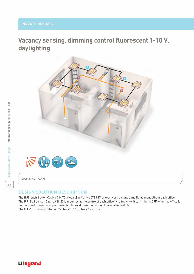
DESIGN SOLUTION DESCRIPTIONThe BUS push-button Cat.No 784 75 (Mosaic) or Cat.No 573 987 (Arteor) controls and dims lights manually, in each office.The PIR BUS sensor Cat.No 488 20 is mounted at the centre of each office for a full view. It turns lights OFF when the office is
The BUS/SCS room controller Cat.No 488 42 controls 2 circuits.
PRIVATE OFFICES
Vacancy sensing, dimming control fluorescent 1-10 V,daylighting
LIGHTING PLAN

23LI
GHTI
NG M
ANAG
EMEN
T SO
LUTI
ONS
|BE
STPR
ACTI
CEGU
IDE
FOR
OFFI
CEBU
ILDI
NGS
INSTALLATION NOTES1. Mount the BUS sensor Cat.No 488 20 in the centre of the room for a full view of the room. Mount the BUS push-buttonCat.No 784 75 (Mosaic) or Cat.No 573 987 (Arteor) at the entrance of each office.2. Connect the BUS sensor and the BUS push-button of office 1 to the BUS/SCS room controller Cat.No 488 42.The connection between the BUS sensor, BUS push-button and the BUS/SCS room controller can be made with BUS/SCS cableCat.No 492/31/32/33 or RJ 45 patch cord.Connect them to input 1 and connect the light circuit3. The sensor is shipped with a factory pre-set time delay of 15 minutes, 500 lux and sensitivity at maximum. Please notethat standard EN 15 193 recommends 500 lux for private offices, use the mobile configurator Cat.No 882 30 to change sensorsettings if needed (time, lux, sensitivity).
INSTALLATION AND WIRING DETAILSPrivate offices: vacancy sensing.
1 2
BUS
Circuit Circuit
Cat.No488 20
Cat.No784 75 /573 987
Cat.No488 42
Cat.No488 20
Cat.No784 75 /573 987
BUS/SCS cableor patch cord
Plug n' goConfiguration for connecting
products to the BUS/SCS line

24
LIGH
TING
MAN
AGEM
ENT
SOLU
TION
S|
BEST
PRAC
TICE
GUID
EFO
ROF
FICE
BUIL
DING
S
Cat.Nos Quantity Description
488 42 1 BUS/SCS room controller,2 outputs 1-10 V
488 20 2 Ceiling-mounted PIR BUS sensor 360 °
784 75 2 BUS lighting control unit 1-way - Mosaic
573 987 2 BUS lighting control unit - Arteor
- Vacancy sensing- Dimming control fluorescent 1-10 V- Daylighting
PRIVATE OFFICES
EQUIPMENT SCHEDULELOCAL MANAGEMENT & CENTRALIZED MANAGEMENT
488 42 784 75488 20
Please refer to page 65 for more information (Centralized management)

25LI
GHTI
NG M
ANAG
EMEN
T SO
LUTI
ONS
|BE
STPR
ACTI
CEGU
IDE
FOR
OFFI
CEBU
ILDI
NGS
- Vacancy sensing- Dimming control fluorescent1-10 V- Automation control- Daylighting
CONTROL NEEDS1. Automatic fan ON based on occupancy2. Manual lights ON3. Automatic dimming luminaire above desk4. Manual control of blinds5. Automatic OFF for lights and fan
LIGHTING8 ceiling luminaires using T5 lamps and electronic ballast lamp.Electronic dimming ballasts (1 – 10V)
APPLICATION DESCRIPTIONSpace use Office activities such as reading, computer
work
Ceiling height 2.50 mWindows View windows along one wall providing
view to exterior with horizontal blindsprovided
SOLUTION1. technology BUS sensor2. BUS/SCS room controller for fan control and dimming3. BUS push-buttons
LARGE PRIVATE OFFICE
26
LIGH
TING
MAN
AGEM
ENT
SOLU
TION
S|
BEST
PRAC
TICE
GUID
EFO
ROF
FICE
BUIL
DING
S
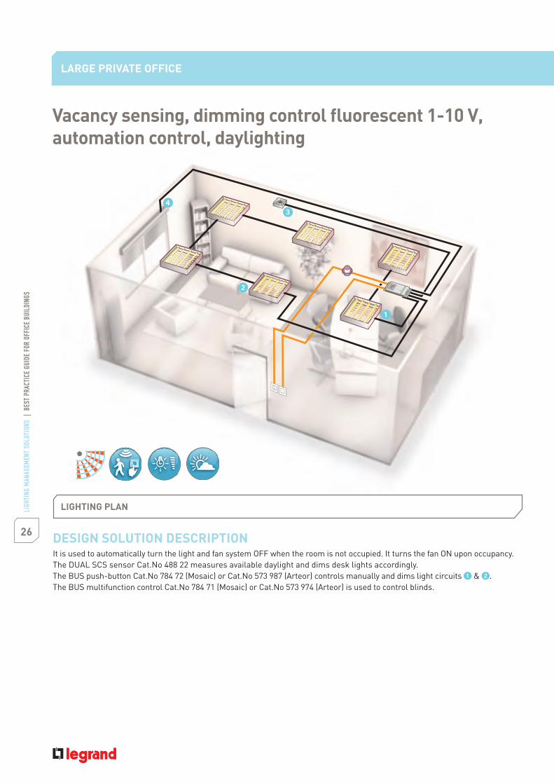
DESIGN SOLUTION DESCRIPTIONIt is used to automatically turn the light and fan system OFF when the room is not occupied. It turns the fan ON upon occupancy.The DUAL SCS sensor Cat.No 488 22 measures available daylight and dims desk lights accordingly.The BUS push-button Cat.No 784 72 (Mosaic) or Cat.No 573 987 (Arteor) controls manually and dims light circuits & .The BUS multifunction control Cat.No 784 71 (Mosaic) or Cat.No 573 974 (Arteor) is used to control blinds.
LARGE PRIVATE OFFICE
Vacancy sensing, dimming control fluorescent 1-10 V,automation control, daylighting
LIGHTING PLAN

27LI
GHTI
NG M
ANAG
EMEN
T SO
LUTI
ONS
|BE
STPR
ACTI
CEGU
IDE
FOR
OFFI
CEBU
ILDI
NGS
INSTALLATION NOTES1. Mount the BUS sensor Cat.No 488 22 at the centre of the room for a full view of the room. Mount the BUS push-buttonCat.No 784 72 (Mosaic) or Cat.No 573 987 (Arteor) and the BUS multifunction control Cat.No 784 71 (Mosaic) or Cat.No 573 974 (Arteor)at the entrance of the room.2. Connect the BUS sensor and the BUS push-button Cat.No 784 72 / 573 987 to the BUS/SCS room controller Cat.No 488 47with the BUS/SCS cable Cat.No 492 31/32/33 or RJ 45 patch cord. They are connected to the same input (No 1). Connect theBUS multifunction control to the input (No 3). Connect the 4 power circuits to the BUS/SCS room controller.3. The sensor is shipped with a factory pre-set time delay of 15 minutes, 500 lux and sensitivity at maximum. Please note thatstandard EN 15 193 recommends 500 lux for large private offices, use the mobile configurator Cat.No 882 30 to change sensorsettings if needed (time, lux, sensitivity).
INSTALLATION AND WIRING DETAILS
Deskluminaires
Luminaires
Cat.No784 72 / 573 987
Cat.No488 47
Cat.No488 22
Cat.No784 71 / 573 974
FanBlindsmotor
BUS/SCS cableor patch cord
Plug n' goConfiguration for connecting
products to the BUS/SCS line
28
LIGH
TING
MAN
AGEM
ENT
SOLU
TION
S|
BEST
PRAC
TICE
GUID
EFO
ROF
FICE
BUIL
DING
S
Cat.Nos Quantity Description
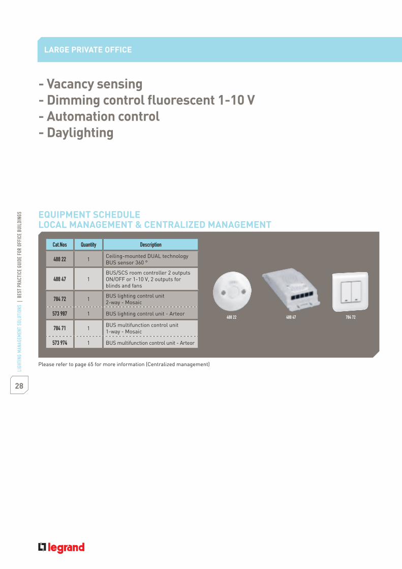
488 22 1 Ceiling-mounted DUAL technologyBUS sensor 360 °
488 47 1BUS/SCS room controller 2 outputsON/OFF or 1-10 V, 2 outputs forblinds and fans
784 72 1 BUS lighting control unit2-way - Mosaic
573 987 1 BUS lighting control unit - Arteor
784 71 1 BUS multifunction control unit1-way - Mosaic
573 974 1 BUS multifunction control unit - Arteor
- Vacancy sensing- Dimming control fluorescent 1-10 V- Automation control- Daylighting
LARGE PRIVATE OFFICE
EQUIPMENT SCHEDULELOCAL MANAGEMENT & CENTRALIZED MANAGEMENT
784 72488 22 488 47
Please refer to page 65 for more information (Centralized management)
29LI
GHTI
NG M
ANAG
EMEN
T SO
LUTI
ONS
|BE
STPR
ACTI
CEGU
IDE
FOR
OFFI
CEBU
ILDI
NGS
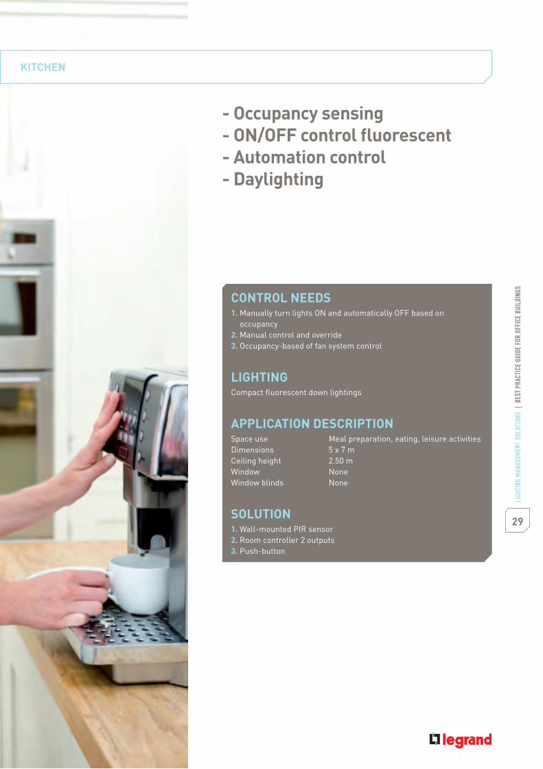
CONTROL NEEDS1. Manually turn lights ON and automatically OFF based on
occupancy2. Manual control and override3. Occupancy-based of fan system control
LIGHTINGCompact fluorescent down lightings
APPLICATION DESCRIPTIONSpace use Meal preparation, eating, leisure activitiesDimensions 5 x 7 mCeiling height 2.50 mWindow NoneWindow blinds None
SOLUTION1. Wall-mounted PIR sensor2. Room controller 2 outputs3. Push-button
KITCHEN
- Occupancy sensing- ON/OFF control fluorescent- Automation control- Daylighting
30
LIGH
TING
MAN
AGEM
ENT
SOLU
TION
S|
BEST
PRAC
TICE
GUID
EFO
ROF
FICE
BUIL
DING
S
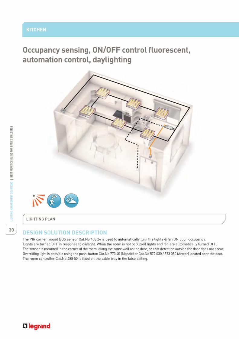
DESIGN SOLUTION DESCRIPTIONThe PIR corner mount BUS sensor Cat.No 488 24 is used to automatically turn the lights & fan ON upon occupancy.Lights are turned OFF in response to daylight. When the room is not occupied lights and fan are automatically turned OFF.The sensor is mounted in the corner of the room, along the same wall as the door, so that detection outside the door does not occur.Overriding light is possible using the push-button Cat.No 770 40 (Mosaic) or Cat.No 572 030 / 573 050 (Arteor) located near the door.The room controller Cat.No 488 50 is fixed on the cable tray in the false ceiling.
KITCHEN
LIGHTING PLAN
Occupancy sensing, ON/OFF control fluorescent,automation control, daylighting

31LI
GHTI
NG M
ANAG
EMEN
T SO
LUTI
ONS
|BE
STPR
ACTI
CEGU
IDE
FOR
OFFI
CEBU
ILDI
NGS
INSTALLATION NOTES1. Mount the BUS sensor Cat.No 488 24 in the corner of the room for a full view of the room. Mount the push-buttonCat.No 770 40 (Mosaic) or Cat.No 572 030 / 573 050 (Arteor) at the entrance of the room.2. Connect the BUS sensor to the room controller Cat.No 488 50 with the BUS/SCS cable Cat.No 492 31/32/33 or RJ 45 patch cord.Connect the push-button to the auxiliary input. Connect the 2 circuits (fan & lights) to the room controller. Position theswitch on the controller Cat.No 488 50 on position" ". The daylight function will control the light circuit only. Please refer toinstruction sheets for more details.3. The sensor is shipped with a factory pre-set time delay of 15 minutes, 300 lux and sensitivity at maximum. Please note thatstandard EN 15 193 recommends 500 lux for kitchens, use the mobile configurator Cat.No 882 30 to change sensor settings ifneeded (time, lux, sensitivity).
INSTALLATION AND WIRING DETAILS
2
SENSOR
1
NO NCC
Luminaires
Cat.No488 24
Cat.No488 50
Cat.No770 40 / 572 030
Fan
BUS/SCS cableor patch cord
Plug n' goConfiguration for connecting
products to the BUS/SCS line

32
LIGH
TING
MAN
AGEM
ENT
SOLU
TION
S|
BEST
PRAC
TICE
GUID
EFO
ROF
FICE
BUIL
DING
S
1st option
Cat.Nos Quantity Description
488 24 1 Wall-mounted PIR BUS sensor 180 °
488 50 1 Room controller 2 outputs 16 A
770 40 1 Push-button - Mosaic
572 030 1 Push-button square version - Arteor
573 050 1 Push-button round version - Arteor
- Occupancy sensing- ON/OFF control fluorescent- Automation control- Daylighting
2nd option
Cat.Nos Quantity Description
488 24 1 Wall-mounted PIR BUS sensor 180 °
488 47 1BUS/SCS room controller 2 outputsON/OFF or 1-10 V + 2 outputsfor blinds and fans
784 75 1 BUS lighting control 1-way - Mosaic
573 987 1 BUS lighting control unit - Arteor
KITCHEN
EQUIPMENT SCHEDULELOCAL MANAGEMENT
EQUIPMENT SCHEDULECENTRALIZED MANAGEMENT
488 24
784 75
488 50 770 40
488 47
Please refer to page 65 for more information (Centralized management)
33LI
GHTI
NG M
ANAG
EMEN
T SO
LUTI
ONS
|BE
STPR
ACTI
CEGU
IDE
FOR
OFFI
CEBU
ILDI
NGS
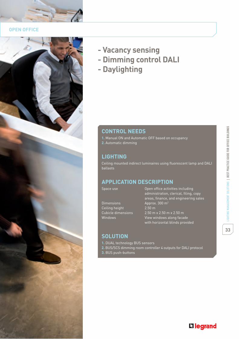
CONTROL NEEDS1. Manual ON and Automatic OFF based on occupancy2. Automatic dimming
LIGHTINGCeiling mounted indirect luminaires using fluorescent lamp and DALIballasts
APPLICATION DESCRIPTIONSpace use Open office activities including
administration, clerical, filing, copyareas, finance, and engineering sales
Dimensions Approx. 300 m2
Ceiling height 2.50 mCubicle dimensions 2.50 m x 2.50 m x 2.50 mWindows View windows along facade
with horizontal blinds provided
SOLUTION1. DUAL technology BUS sensors2. BUS/SCS dimming room controller 4 outputs for DALI protocol3. BUS push-buttons
OPEN OFFICE
- Vacancy sensing- Dimming control DALI- Daylighting

34
LIGH
TING
MAN
AGEM
ENT
SOLU
TION
S|
BEST
PRAC
TICE
GUID
EFO
ROF
FICE
BUIL
DING
S
DESIGN SOLUTION DESCRIPTIONLights are manually turned ON by pressing the BUS multifunctional control Cat.No 784 73 (Mosaic) or Cat.No 573 974 (Arteor)located at the entrance of each zone. The DUAL technology BUS sensor Cat.No 488 22 covers 90 m2 and assures adequatecoverage (through partitions). Each zone is divided in 2 parts: close to the windows and further away from the windows. Each partis controlled by 2 DUAL technology BUS sensor Cat.No 488 22.While the area is occupied the BUS sensor will hold the lighting ON and will dim automatically the associated circuit. After thearea is vacated and after the sensor’s time delay expires, the BUS sensor will turn lights OFF.Manual override is possible using the BUS multifunctional control (automatic dimming is disabled).The BUS/SCS room controller Cat.No 488 44 is fixed on the cable tray in the false ceiling.
OPEN OFFICE
LIGHTING PLAN
Vacancy sensing, dimming control DALI, daylighting

35LI
GHTI
NG M
ANAG
EMEN
T SO
LUTI
ONS
|BE
STPR
ACTI
CEGU
IDE
FOR
OFFI
CEBU
ILDI
NGS
INSTALLATION NOTES1. Mount the BUS sensor Cat.No 488 22 on a rigid, vibration-free surface. Mount the BUS multifunctional controlCat.No 784 73 (Mosaic) or Cat.No 573 974 (Arteor) at the entrance of the room.2. Connect the BUS/SCS room controller Cat.No 488 44 to the BUS sensor and the BUS multifunctional control with the BUS/SCScable Cat.No 492 31/32/33 or RJ 45 patch cord. Input 1 controls output 1.3. The sensor is shipped with a factory pre-set time delay of 15 minutes, 500 lux and sensivity at maximum. Please note thatstandard EN 15 193 recommends 500 lux for open offices, use the mobile configurator Cat.No 882 30 to change sensor settingsif needed (time, lux, sensitivity).
INSTALLATION AND WIRING DETAILS
1 2 3 4
BUS
DALI ballast
Cat.No784 73 /573 974
Cat.No784 73 /573 974
Cat.No488 44
Cat.No488 22
Cat.No488 22
Cat.No488 22
Cat.No488 22
DALI ballast DALI ballast DALI ballast
BUS/SCS cable or patch cord
Plug n' goConfiguration for connecting
products to the BUS/SCS line
36
LIGH
TING
MAN
AGEM
ENT
SOLU
TION
S|
BEST
PRAC
TICE
GUID
EFO
ROF
FICE
BUIL
DING
S
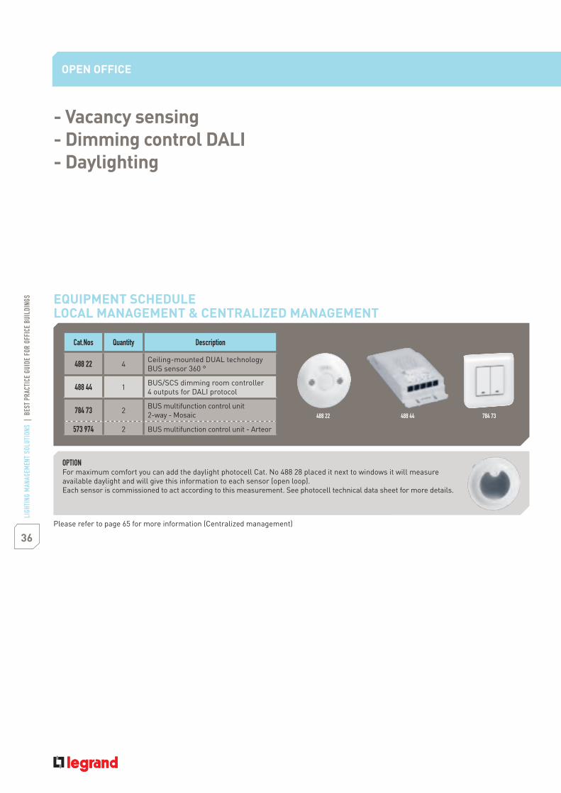
Cat.Nos Quantity Description
488 22 4 Ceiling-mounted DUAL technologyBUS sensor 360 °
488 44 1 BUS/SCS dimming room controller4 outputs for DALI protocol
784 73 2 BUS multifunction control unit2-way - Mosaic
573 974 2 BUS multifunction control unit - Arteor
- Vacancy sensing- Dimming control DALI- Daylighting
OPEN OFFICE
488 22 488 44 784 73
EQUIPMENT SCHEDULELOCAL MANAGEMENT & CENTRALIZED MANAGEMENT
Please refer to page 65 for more information (Centralized management)
OPTIONFor maximum comfort you can add the daylight photocell Cat. No 488 28 placed it next to windows it will measureavailable daylight and will give this information to each sensor (open loop).Each sensor is commissioned to act according to this measurement. See photocell technical data sheet for more details.

37LI
GHTI
NG M
ANAG
EMEN
T SO
LUTI
ONS
|BE
STPR
ACTI
CEGU
IDE
FOR
OFFI
CEBU
ILDI
NGS
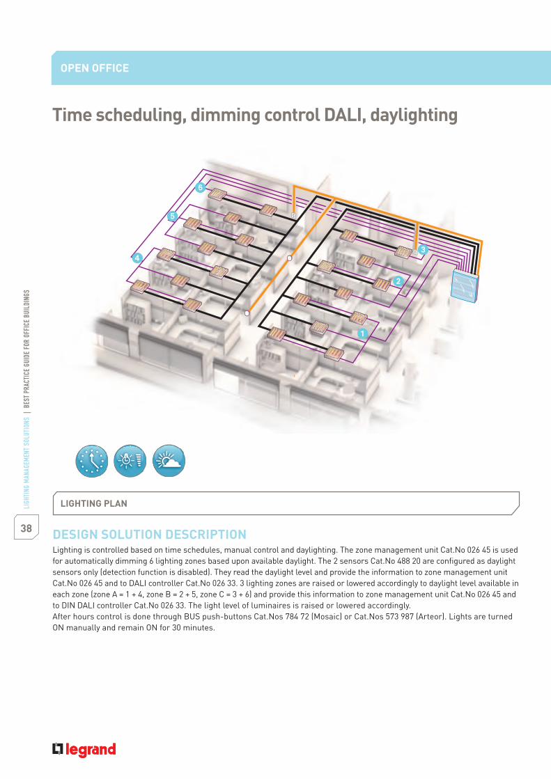
- Time scheduling- Dimming control DALI- Daylighting
CONTROL NEEDS1. Automatically turn pendant lights ON and OFF based on occupancy
after hours and on week-ends2. Time scheduling, daylighting, manual switching
LIGHTINGPendant mounted indirect/direct luminaires using T5 lamps, withDALI dimming ballasts.
APPLICATION DESCRIPTIONSpace use Open office activities in including administration,
clerical, filing, copy areas, finance, and engineeringsales
Dimensions approx. 600 m2
Ceiling height 2.50 mWindows View windows along south facade with horizontal
blinds providedWindow blinds None
SOLUTION1. BUS/SCS DIN dimming controller 8 outputs for DALI protocol2. Zone management unit3. Power supplies4. BUS push-buttons5. Lighting measurement cells
38
LIGH
TING
MAN
AGEM
ENT
SOLU
TION
S|
BEST
PRAC
TICE
GUID
EFO
ROF
FICE
BUIL
DING
S
DESIGN SOLUTION DESCRIPTIONLighting is controlled based on time schedules, manual control and daylighting. The zone management unit Cat.No 026 45 is usedfor automatically dimming 6 lighting zones based upon available daylight. The 2 sensors Cat.No 488 20 are configured as daylightsensors only (detection function is disabled). They read the daylight level and provide the information to zone management unitCat.No 026 45 and to DALI controller Cat.No 026 33. 3 lighting zones are raised or lowered accordingly to daylight level available ineach zone (zone A = 1 + 4, zone B = 2 + 5, zone C = 3 + 6) and provide this information to zone management unit Cat.No 026 45 andto DIN DALI controller Cat.No 026 33. The light level of luminaires is raised or lowered accordingly.After hours control is done through BUS push-buttons Cat.Nos 784 72 (Mosaic) or Cat.Nos 573 987 (Arteor). Lights are turnedON manually and remain ON for 30 minutes.
OPEN OFFICE
Time scheduling, dimming control DALI, daylighting
LIGHTING PLAN

39LI
GHTI
NG M
ANAG
EMEN
T SO
LUTI
ONS
|BE
STPR
ACTI
CEGU
IDE
FOR
OFFI
CEBU
ILDI
NGS
INSTALLATION NOTES1. Mount the lighting measurement cells Cat.No 488 20 on the ceiling.2. Mount the BUS push-buttons Cat.No 784 72 (Mosaic) or Cat.No 573 987 (Arteor) at the entrance of each zone.3. Mount the BUS/SCS DIN power supplies Cat.Nos 035 60 & 035 64 + zone management unit Cat.No 026 45 + DIN DALI controller8 outputs Cat.No 026 33 on a DIN rail.4. Connect zone management unit + DIN DALI controller + BUS push-buttons + lighting measurement cell with BUS/SCS cableCat.Nos 492 31/32/33.5. Connect DALI ballast to DIN controller Cat.No 026 33 outputs.6. Use software pack Cat.No 488 80 with the zone management unit Cat.No 026 45 to commission the lighting measurement cell,the DIN DALI controller, the BUS push-buttons. Please refer to Cat.No 488 80 instruction sheets for more details.7. Use the software of zone management unit Cat.No 026 45 to commission automatic dimming conditions and to do the scheduling.
INSTALLATION AND WIRING DETAILS
DALI ballastDALI ballast DALI ballast
DALI ballastDALI ballastDALI ballast
Cat.No784 72 /573 987
Cat.No784 72 /573 987
Cat.No488 20
Cat.No488 20
Cat. No 026 33Cat. No 026 45Cat. No 035 64Cat. No 035 60
LN230 V
LN230 V
BUS/SCS cable
Configuration software suiteConfiguration for connecting
products to the BUS/SCS line

40
LIGH
TING
MAN
AGEM
ENT
SOLU
TION
S|
BEST
PRAC
TICE
GUID
EFO
ROF
FICE
BUIL
DING
S
Cat.Nos Quantity Description
488 20 2 Lighting measurement cell
026 33 1 BUS/SCS DIN dimming controller8 outputs for DALI protocol
784 72 2 BUS lighting control unit2-way - Mosaic
573 987 2 BUS lighting control unit - Arteor
035 60(*) 1 BUS/SCS DIN power supply27 V 1200 mA
035 64(*) 1 BUS/SCS DIN power supply forCat.No 026 45
026 45(*) 1 Zone management unit
- Time scheduling- Dimming control DALI- Daylighting (open loop)
OPEN OFFICE
488 20 784 72 026 45
CUBICLE WORKSTATION
EQUIPMENT SCHEDULELOCAL MANAGEMENT & CENTRALIZED MANAGEMENT
Please refer to page 65 for more information (Centralized management)
(*) This product can be shared.
41LI
GHTI
NG M
ANAG
EMEN
T SO
LUTI
ONS
|BE
STPR
ACTI
CEGU
IDE
FOR
OFFI
CEBU
ILDI
NGS
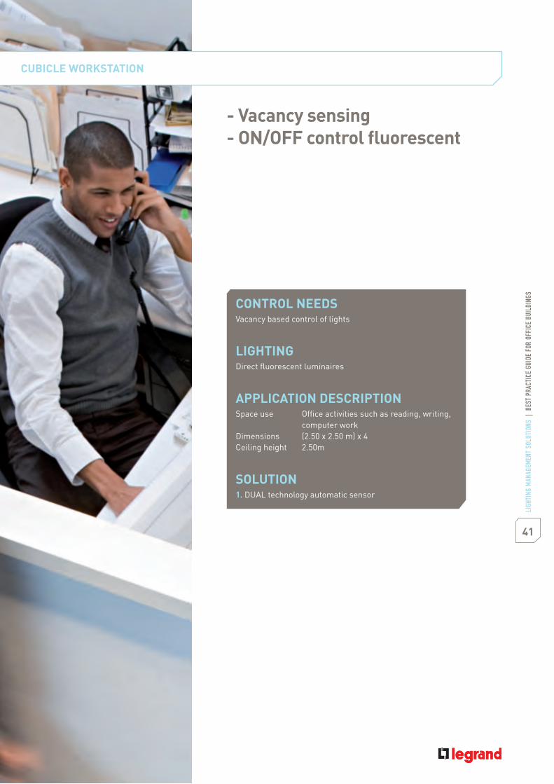
CONTROL NEEDSVacancy based control of lights
LIGHTINGDirect fluorescent luminaires
APPLICATION DESCRIPTIONSpace use Office activities such as reading, writing,
computer workDimensions (2.50 x 2.50 m) x 4Ceiling height 2.50m
SOLUTION1. DUAL technology automatic sensor
CUBICLE WORKSTATION
- Vacancy sensing- ON/OFF control fluorescent

42
LIGH
TING
MAN
AGEM
ENT
SOLU
TION
S|
BEST
PRAC
TICE
GUID
EFO
ROF
FICE
BUIL
DING
S
DESIGN SOLUTION DESCRIPTIONAmbient lighting is provided by ceiling mounted luminaires (as in an OPEN OFFICE p. 38).Here tasks/desk lights are controlled by an automatic switch located in a column. Desk lights are manually turned ON usingthe push-button included in the automatic switch. When the desk is not occupied, desk lights are automatically turned OFF.
CUBICLE WORKSTATION
LIGHTING PLAN
Vacancy sensing, ON/OFF control fluorescent

43LI
GHTI
NG M
ANAG
EMEN
T SO
LUTI
ONS
|BE
STPR
ACTI
CEGU
IDE
FOR
OFFI
CEBU
ILDI
NGS
INSTALLATION NOTES1. Mount the automatic switch Cat.No 784 52 in the column to have a full view of the desk.2. The sensor is shipped with pre-set time delay of 15 minutes, 300 lux and sensivity at maximum.Please note that standard EN 15 193 recommends 500 lux for workstation, use the mobile configurator Cat.No 882 30 tochange sensor settings if needed (time, lux, sensivity).
WIRING DETAILS
8.5 A max.Desk lights
Cat.No 784 52 / 574 049
44
LIGH
TING
MAN
AGEM
ENT
SOLU
TION
S|
BEST
PRAC
TICE
GUID
EFO
ROF
FICE
BUIL
DING
S
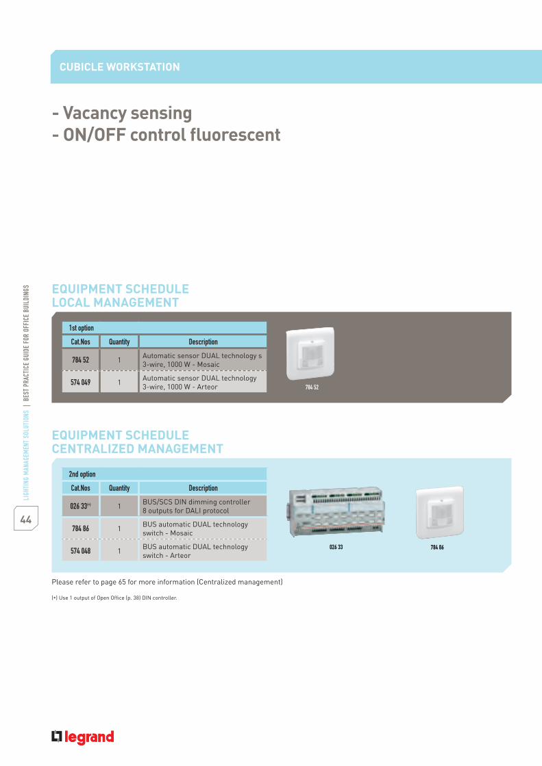
1st option
Cat.Nos Quantity Description
784 52 1 Automatic sensor DUAL technology s3-wire, 1000 W - Mosaic
574 049 1 Automatic sensor DUAL technology3-wire, 1000 W - Arteor
CUBICLE WORKSTATION
EQUIPMENT SCHEDULELOCAL MANAGEMENT
- Vacancy sensing- ON/OFF control fluorescent
784 52
2nd option
Cat.Nos Quantity Description
026 33(*) 1 BUS/SCS DIN dimming controller8 outputs for DALI protocol
784 86 1 BUS automatic DUAL technologyswitch - Mosaic
574 048 1 BUS automatic DUAL technologyswitch - Arteor
EQUIPMENT SCHEDULECENTRALIZED MANAGEMENT
026 33
Please refer to page 65 for more information (Centralized management)
(*) Use 1 output of Open Office (p. 38) DIN controller.
784 86

45LI
GHTI
NG M
ANAG
EMEN
T SO
LUTI
ONS
|BE
STPR
ACTI
CEGU
IDE
FOR
OFFI
CEBU
ILDI
NGS
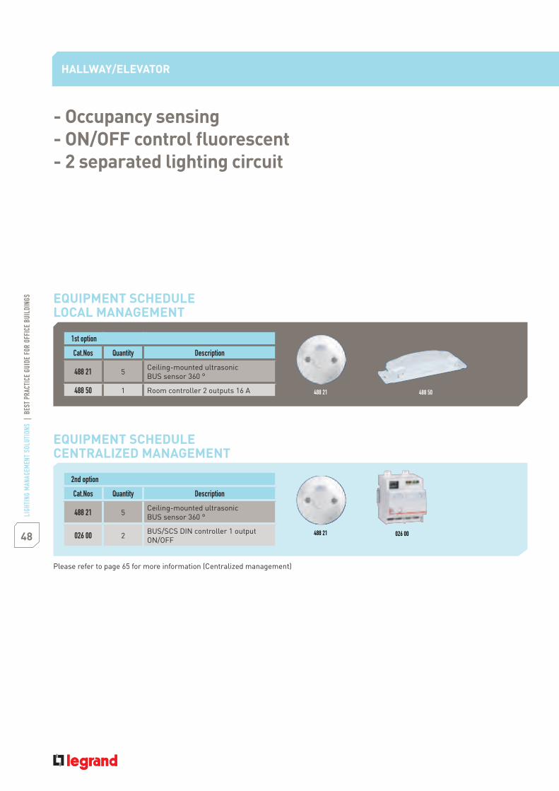
CONTROL NEEDS1. Automatically turn lights ON and OFF based on occupancy
LIGHTINGCompact fluorescent down lightings
APPLICATION DESCRIPTIONSpace use General circulationCorridor dimensions 30 x 2 mElevator/Lobby dimension 10 x 4 mCeiling height 2.50 mWindow None
SOLUTION1. Ceiling-mounted ultrasonic sensors2. Room controller with 2 outputs
- Occupancy sensing- ON/OFF control fluorescent- Secured lighting circuit
HALLWAY/ELEVATOR

46
LIGH
TING
MAN
AGEM
ENT
SOLU
TION
S|
BEST
PRAC
TICE
GUID
EFO
ROF
FICE
BUIL
DING
S
DESIGN SOLUTION DESCRIPTIONLighting in the corridor and elevator lobby is automatically turned ON and OFF based on occupancy using the US ceiling mountBUS sensor Cat.No 488 21, which has a coverage pattern that is designed specifically for angular corridors (ultrasonic).Two different circuits power the controller for security reasons.2 power circuits are connected to the room controller Cat.No 488 50. In the event of ordinary power loss on 1 circuit, 1 lightcircuit (out of 2) will thus remain ON.If no presence is detected within 3 minutes after the initial detection, the sensor automatically switches OFF the light after the3 minutes have elapsed.
HALLWAY/ELEVATOR
Occupancy sensing, ON/OFF control fluorescent,secured lighting circuit
LIGHTING PLAN

47LI
GHTI
NG M
ANAG
EMEN
T SO
LUTI
ONS
|BE
STPR
ACTI
CEGU
IDE
FOR
OFFI
CEBU
ILDI
NGS
INSTALLATION NOTES1. Mount the BUS sensors Cat.Nos 488 21 on a rigid vibration-free surface all along the corridor, (12 metres distance betweensensors).2. Mount the room controller Cat.No 488 50 in the false ceiling. The connection between the BUS sensors and the room controller2 outputs can be made with BUS/SCS cable Cat.No 492 31/32/33 o RJ 45 patch cord.Position the switch of the controller on position" ". The daylight function will control the 2 lighting circuits.Please refer to instruction sheets for more details.3. The sensors are shipped with a factory pre-set time delay of 15 minutes, 500 lux and sensitivity at maximum. Please notethat standard EN 15 193 recommends 100 lux for hallways/elevators, use the mobile configurator Cat.No 882 30 to changesensors settings if needed (time, lux, sensitivity).
INSTALLATION AND WIRING DETAILS
2
SENSOR
1NO NCC
Cat.No488 50
Cat.No488 21
Cat.No488 21
Cat.No488 21
Cat.No488 21
Cat.No488 21
Circuit 2Circuit 1
BUS/SCS cable or patch cord
Plug n' goConfiguration for connecting
products to the BUS/SCS line
48
LIGH
TING
MAN
AGEM
ENT
SOLU
TION
S|
BEST
PRAC
TICE
GUID
EFO
ROF
FICE
BUIL
DING
S
1st option
Cat.Nos Quantity Description
488 21 5 Ceiling-mounted ultrasonicBUS sensor 360 °
488 50 1 Room controller 2 outputs 16 A
- Occupancy sensing- ON/OFF control fluorescent- 2 separated lighting circuit
2nd option
Cat.Nos Quantity Description
488 21 5 Ceiling-mounted ultrasonicBUS sensor 360 °
026 00 2 BUS/SCS DIN controller 1 outputON/OFF
HALLWAY/ELEVATOR
EQUIPMENT SCHEDULELOCAL MANAGEMENT
EQUIPMENT SCHEDULECENTRALIZED MANAGEMENT
488 21
488 21
488 50
026 00
Please refer to page 65 for more information (Centralized management)
49LI
GHTI
NG M
ANAG
EMEN
T SO
LUTI
ONS
|BE
STPR
ACTI
CEGU
IDE
FOR
OFFI
CEBU
ILDI
NGS
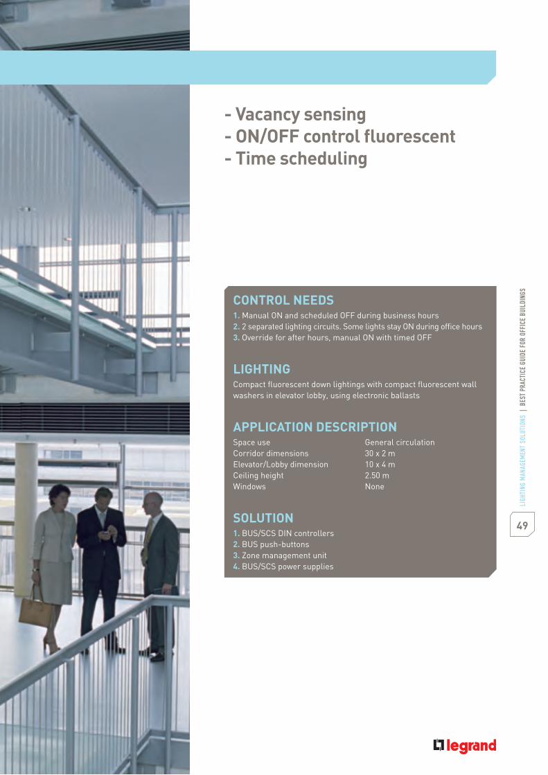
CONTROL NEEDS1. Manual ON and scheduled OFF during business hours2. 2 separated lighting circuits. Some lights stay ON during office hours3. Override for after hours, manual ON with timed OFF
LIGHTINGCompact fluorescent down lightings with compact fluorescent wallwashers in elevator lobby, using electronic ballasts
APPLICATION DESCRIPTIONSpace use General circulationCorridor dimensions 30 x 2 mElevator/Lobby dimension 10 x 4 mCeiling height 2.50 mWindows None
SOLUTION1. BUS/SCS DIN controllers2. BUS push-buttons3. Zone management unit4. BUS/SCS power supplies
- Vacancy sensing- ON/OFF control fluorescent- Time scheduling
50
LIGH
TING
MAN
AGEM
ENT
SOLU
TION
S|
BEST
PRAC
TICE
GUID
EFO
ROF
FICE
BUIL
DING
S
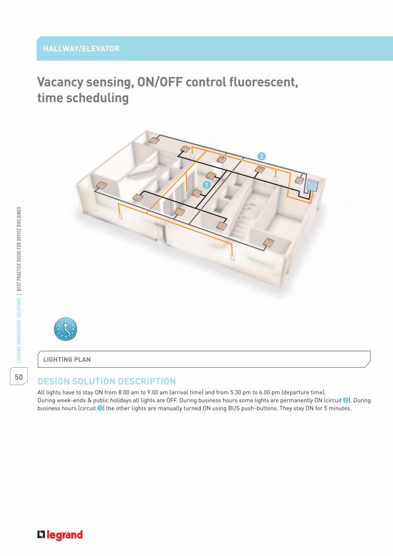
DESIGN SOLUTION DESCRIPTIONAll lights have to stay ON from 8.00 am to 9.00 am (arrival time) and from 5.30 pm to 6.00 pm (departure time).During week-ends & public holidays all lights are OFF. During business hours some lights are permanently ON (circuit ). Duringbusiness hours (circuit ) the other lights are manually turned ON using BUS push-buttons. They stay ON for 5 minutes.
HALLWAY/ELEVATOR
Vacancy sensing, ON/OFF control fluorescent,time scheduling
LIGHTING PLAN

51LI
GHTI
NG M
ANAG
EMEN
T SO
LUTI
ONS
|BE
STPR
ACTI
CEGU
IDE
FOR
OFFI
CEBU
ILDI
NGS
INSTALLATION NOTES1. Mount the BUS push-buttons Cat.Nos 784 75 (Mosaic) or Cat.Nos 573 987 (Arteor) along the corridor.2. Connect the BUS push-buttons to the BUS/SCS DIN controller Cat.No 026 00 with BUS/SCS cable Cat.No 492 31/32/33.Connect the circuits & to BUS/SCS DIN controllers Cat.Nos 026 00.These two DIN controllers are powered by 2 different circuits.3. Connect the zone management unit Cat.No 026 45 to the BUS. BUS and zone management unit are powered by the2 SCS DIN power supplies Cat.No 035 67 and power supply scheduler Cat.No 634 42.Mount the BUS power supply Cat.No 035 67 and zone management unit power supply Cat.No 634 42 on a rail.4. Commission the zone management unit according to zone management unit programming documentation.
INSTALLATION AND WIRING DETAILS
Circuit 2
LN230 V
LN230 V
Cat. No784 75 /573 987
Cat. No784 75 /573 987
Cat. No784 75 /573 987
Cat. No784 75 /573 987
Cat. No784 75 /573 987
Cat. No035 67
Cat. No634 42
Cat. No026 45
Cat. No026 00
Cat. No026 00
LN230 V
LN230 V
Circuit 1
BUS/SCS cable
Configuration software suiteConfiguration for connecting
products to the BUS/SCS line
52
LIGH
TING
MAN
AGEM
ENT
SOLU
TION
S|
BEST
PRAC
TICE
GUID
EFO
ROF
FICE
BUIL
DING
S
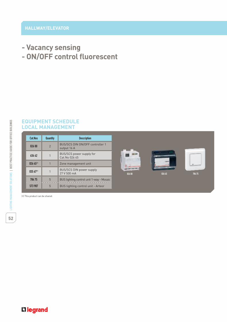
Cat.Nos Quantity Description
026 00 2 BUS/SCS DIN ON/OFF controller 1output 16 A
634 42 1 BUS/SCS power supply forCat.No 026 45
026 45(*) 1 Zone management unit
035 67(*) 1 BUS/SCS DIN power supply27 V 500 mA
784 75 5 BUS lighting control unit 1-way - Mosaic
573 987 5 BUS lighting control unit - Arteor
- Vacancy sensing- ON/OFF control fluorescent
HALLWAY/ELEVATOR
EQUIPMENT SCHEDULELOCAL MANAGEMENT
026 00 026 45 784 75
(*) This product can be shared.
53LI
GHTI
NG M
ANAG
EMEN
T SO
LUTI
ONS
|BE
STPR
ACTI
CEGU
IDE
FOR
OFFI
CEBU
ILDI
NGS
LOBBY
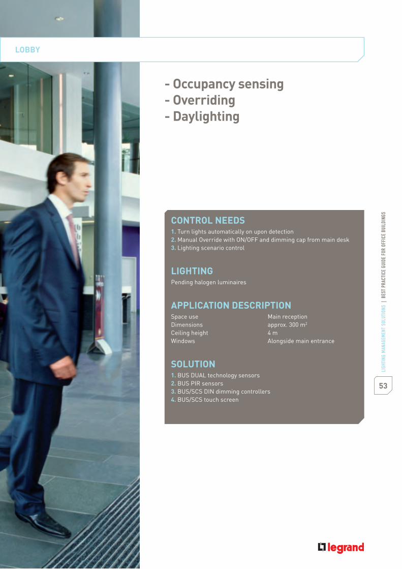
CONTROL NEEDS1. Turn lights automatically on upon detection2. Manual Override with ON/OFF and dimming cap from main desk3. Lighting scenario control
LIGHTINGPending halogen luminaires
APPLICATION DESCRIPTIONSpace use Main receptionDimensions approx. 300 m2
Ceiling height 4 mWindows Alongside main entrance
SOLUTION1. BUS DUAL technology sensors2. BUS PIR sensors3. BUS/SCS DIN dimming controllers4. BUS/SCS touch screen
- Occupancy sensing- Overriding- Daylighting

54
LIGH
TING
MAN
AGEM
ENT
SOLU
TION
S|
BEST
PRAC
TICE
GUID
EFO
ROF
FICE
BUIL
DING
S
LOBBY
LIGHTING PLAN
DESIGN SOLUTION DESCRIPTIONLights are automatically turn on upon occupancy. Each sensor controls its own zone. During the day lights are dimmedautomatically according to daylight and 500 lux are maintained at reception area, 100 lux in waiting area and stairs area.Lights are not turned off during working hours even though nobody is present, and 50 lux are maintained in the whole zone.For special events a dedicated lighting scenario can be easily launched.After working hours and during the week-end there are off.
Occupancy sensing, overriding, daylighting

55LI
GHTI
NG M
ANAG
EMEN
T SO
LUTI
ONS
|BE
STPR
ACTI
CEGU
IDE
FOR
OFFI
CEBU
ILDI
NGS
INSTALLATION NOTES1. Mount the SCS sensors Cat.Nos 488 22 and 488 20 in the false ceiling.2. Mount the power supply Cat.No 035 60 and the two DIN dimming controllers Cat.No 026 22 an Cat.No 026 21 in the cabinetof the lobby.3. Mount the multiple scenarios touch screen Cat.No 784 74 (Mosaic) or Cat.No 573 960 (Arteor) in the wall close to main reception.4. Connect all these devices together with the BUS/SCS cable Cat.No 492 31/32/33.5. Use software pack Cat.No 488 81 to commission the BUS sensor and the controllers and to set the dimming level. Pleaserefer to Cat.No 488 81 instruction sheets for more details.6. The sensors are shipped with a factory pe-set time delay of 15 minutes, 500 lux and sensivity at maximum.Please note that standard EN 15 193 recommends 100 lux for lobby, use the mobile configurator Cat.No 882 30 to changesensors settings if needed (time, lux, sensivity).
INSTALLATION AND WIRING DETAILS
Configuration software suiteConfiguration for connecting
products to the BUS/SCS line
Circuit 3
LN230 V
LN230 V
Cat. No035 67
Cat. No634 42
Cat. No026 45 Cat. No
026 22Cat. No026 21
LN230 V
LN230 V
Circuit 1 Circuit 2
Cat. No488 20
Cat. No488 22
Cat. No488 22
Cat. No784 74 /573 960
BUS/SCS cable

56
LIGH
TING
MAN
AGEM
ENT
SOLU
TION
S|
BEST
PRAC
TICE
GUID
EFO
ROF
FICE
BUIL
DING
S
LOBBY
Cat.Nos Quantity Description
488 22 2 Ceiling-mounted DUAL technologyBUS sensor 360 °
488 20 1 Ceiling-mounted PIR BUS sensor 360 °
026 21 1 BUS/SCS DIN dimming controllerhalogen 1 output
026 22 1 BUS/SCS DIN dimming controllerhalogen 2 outputs
634 42(*) 1 Power supply for zone management unit
026 45(*) 1 Zone management unit
035 67(*) 1 BUS/SCS DIN power supply27 V 500 mA
784 74 1 BUS/SCS multiple scenariostouch screen control - Mosaic
573 960 1 BUS/SCS multiple scenariostouch screen control - Arteor
488 81 1 Software pack 2
EQUIPMENT SCHEDULELOCAL MANAGEMENT
488 22 026 45784 74
- Occupancy sensing- Overriding- Daylighting
(*) This product can be shared.

CONTROL NEEDSAutomatically turn lights ON and OFF based on occupancy
LIGHTINGRecessed 1 x 4 luminaires using two T5 lamps and a two-lampElectronic ballast
APPLICATION DESCRIPTIONSpace use RestroomDimensions 3 x 7 with 2 x 1.50 alcove (each)Ceiling height 2.50 mWindows NoneWindow blinds None
SOLUTION1. Ceiling-mounted ultrasonic technology 2 outputs sensor2. Room controller
RESTROOM
- Occupancy sensing- ON/OFF control fluorescent- Fan control
57LI
GHTI
NG M
ANAG
EMEN
T SO
LUTI
ONS
|BE
STPR
ACTI
CEGU
IDE
FOR
OFFI
CEBU
ILDI
NGS
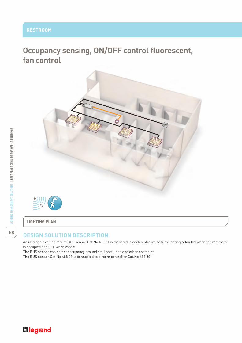
DESIGN SOLUTION DESCRIPTIONAn ultrasonic ceiling mount BUS sensor Cat.No 488 21 is mounted in each restroom, to turn lighting & fan ON when the restroomis occupied and OFF when vacant.The BUS sensor can detect occupancy around stall partitions and other obstacles.The BUS sensor Cat.No 488 21 is connected to a room controller Cat.No 488 50.
RESTROOM
Occupancy sensing, ON/OFF control fluorescent,fan control
LIGHTING PLAN
58
LIGH
TING
MAN
AGEM
ENT
SOLU
TION
S|
BEST
PRAC
TICE
GUID
EFO
ROF
FICE
BUIL
DING
S
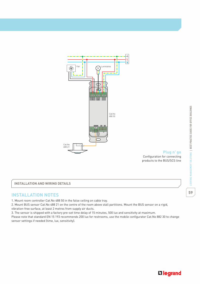
INSTALLATION NOTES1. Mount room controller Cat.No 488 50 in the false ceiling on cable tray.2. Mount BUS sensor Cat.No 488 21 on the centre of the room above stall partitions. Mount the BUS sensor on a rigid,vibration-free surface, at least 2 metres from supply air ducts.3. The sensor is shipped with a factory pre-set time delay of 15 minutes, 500 lux and sensitivity at maximum.Please note that standard EN 15 193 recommends 200 lux for restrooms, use the mobile configurator Cat.No 882 30 to changesensor settings if needed (time, lux, sensitivity).
INSTALLATION AND WIRING DETAILS
2
SENSOR
1
NO NCC
Cat.No488 50
Cat.No488 21
LuminairesFan
59LI
GHTI
NG M
ANAG
EMEN
T SO
LUTI
ONS
|BE
STPR
ACTI
CEGU
IDE
FOR
OFFI
CEBU
ILDI
NGS
Plug n' goConfiguration for connecting
products to the BUS/SCS line
1st option
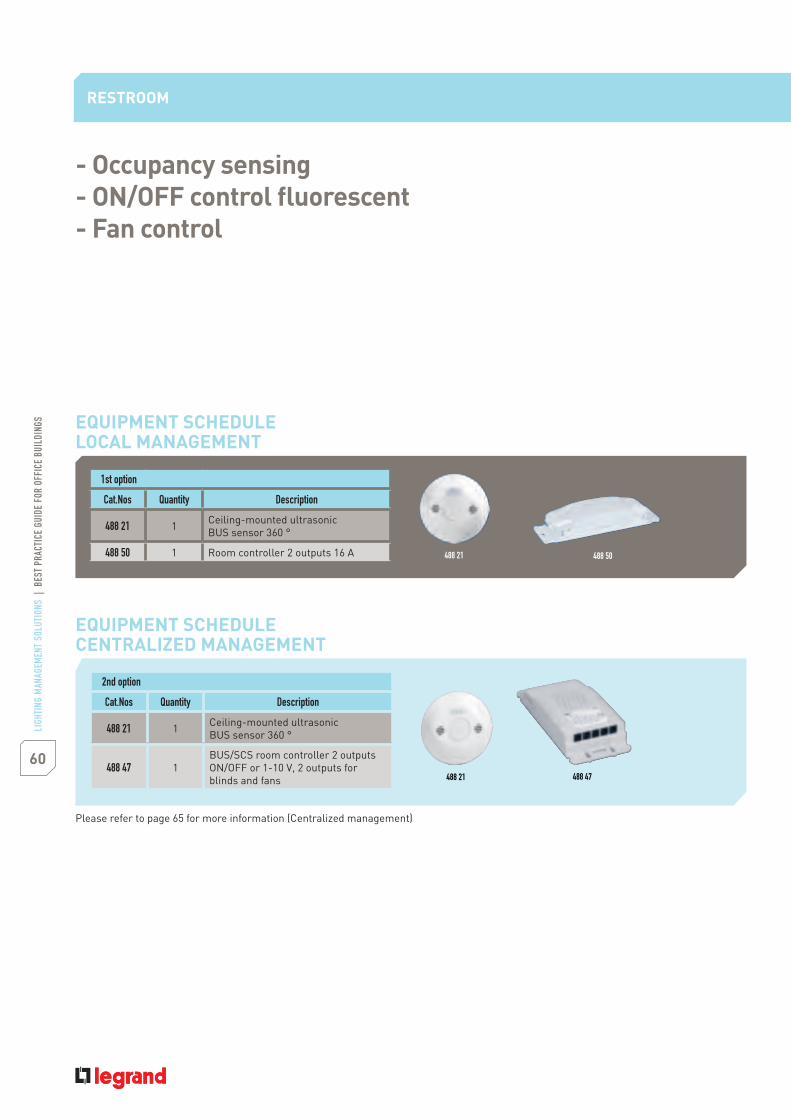
Cat.Nos Quantity Description
488 21 1 Ceiling-mounted ultrasonicBUS sensor 360 °
488 50 1 Room controller 2 outputs 16 A
- Occupancy sensing- ON/OFF control fluorescent- Fan control
2nd option
Cat.Nos Quantity Description
488 21 1 Ceiling-mounted ultrasonicBUS sensor 360 °
488 47 1BUS/SCS room controller 2 outputsON/OFF or 1-10 V, 2 outputs forblinds and fans
RESTROOM
EQUIPMENT SCHEDULELOCAL MANAGEMENT
EQUIPMENT SCHEDULECENTRALIZED MANAGEMENT
60
LIGH
TING
MAN
AGEM
ENT
SOLU
TION
S|
BEST
PRAC
TICE
GUID
EFO
ROF
FICE
BUIL
DING
S
488 21
488 21
488 50
488 47
Please refer to page 65 for more information (Centralized management)

- Time scheduling- Photo sensor
CONTROL NEEDSParking luminaires turn ON at dusk and OFF at 10 pmParking luminaires security turn ON at dusk and OFF at dawnBulkhead lights turn ON at dusk and off at dawnEntrance luminaires turn ON and OFF automatically with
manual override
LIGHTINGBuilding-mounted wall packs for perimeter security lighting,bollards for lighting walkways, recessed down lights lighting entrancesand exits, and pole-mounted shoebox luminaires lighting parking lots
APPLICATION DESCRIPTIONSpace use Exterior lighting control of building, parking lot,
walkway and canopy lighting
SOLUTIONPhoto sensor ON/scheduled OFF using scheduler
EXTERIOR
61LI
GHTI
NG M
ANAG
EMEN
T SO
LUTI
ONS
|BE
STPR
ACTI
CEGU
IDE
FOR
OFFI
CEBU
ILDI
NGS
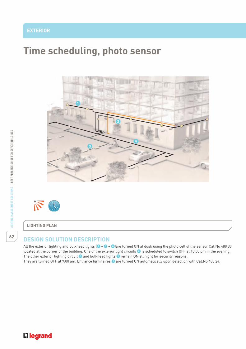
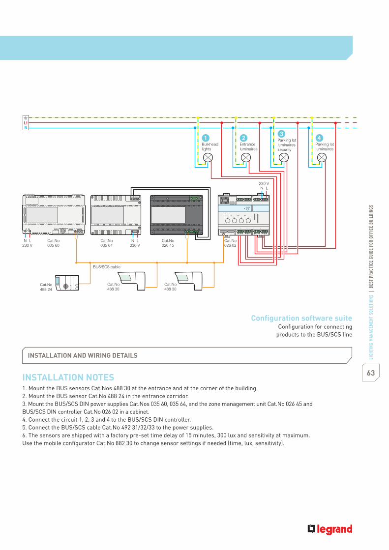
DESIGN SOLUTION DESCRIPTIONAll the exterior lighting and bulkhead lights ( + + )are turned ON at dusk using the photo cell of the sensor Cat.No 488 30located at the corner of the building. One of the exterior light circuits is scheduled to switch OFF at 10:00 pm in the evening.The other exterior lighting circuit and bulkhead lights remain ON all night for security reasons.They are turned OFF at 9:00 am. Entrance luminaires are turned ON automatically upon detection with Cat.No 488 24.
EXTERIOR
Time scheduling, photo sensor
LIGHTING PLAN
INSTALLATION NOTES1. Mount the BUS sensors Cat.Nos 488 30 at the entrance and at the corner of the building.2. Mount the BUS sensor Cat.No 488 24 in the entrance corridor.3. Mount the BUS/SCS DIN power supplies Cat.Nos 035 60, 035 64, and the zone management unit Cat.No 026 45 andBUS/SCS DIN controller Cat.No 026 02 in a cabinet.4. Connect the circuit 1, 2, 3 and 4 to the BUS/SCS DIN controller.5. Connect the BUS/SCS cable Cat.No 492 31/32/33 to the power supplies.6. The sensors are shipped with a factory pre-set time delay of 15 minutes, 300 lux and sensitivity at maximum.Use the mobile configurator Cat.No 882 30 to change sensor settings if needed (time, lux, sensitivity).
INSTALLATION AND WIRING DETAILS
LN230 V
LN230 V
Cat.No488 30
Cat.No488 30
Cat.No035 60
Cat.No035 64
Cat.No026 45
Cat.No026 02
LN230 V
Bulkheadlights
Entranceluminaires
Parking lotluminairessecurity
Parking lotluminaires
Cat.No488 24
BUS/SCS cable
62
LIGH
TING
MAN
AGEM
ENT
SOLU
TION
S|
BEST
PRAC
TICE
GUID
EFO
ROF
FICE
BUIL
DING
S
INSTALLATION NOTES1. Mount the BUS sensors Cat.Nos 488 30 at the entrance and at the corner of the building.2. Mount the BUS sensor Cat.No 488 24 in the entrance corridor.3. Mount the BUS/SCS DIN power supplies Cat.Nos 035 60, 035 64, and the zone management unit Cat.No 026 45 andBUS/SCS DIN controller Cat.No 026 02 in a cabinet.4. Connect the circuit 1, 2, 3 and 4 to the BUS/SCS DIN controller.5. Connect the BUS/SCS cable Cat.No 492 31/32/33 to the power supplies.6. The sensors are shipped with a factory pre-set time delay of 15 minutes, 300 lux and sensitivity at maximum.Use the mobile configurator Cat.No 882 30 to change sensor settings if needed (time, lux, sensitivity).
INSTALLATION AND WIRING DETAILS
LN230 V
LN230 V
Cat.No488 30
Cat.No488 30
Cat.No035 60
Cat.No035 64
Cat.No026 45
Cat.No026 02
LN230 V
Bulkheadlights
Entranceluminaires
Parking lotluminairessecurity
Parking lotluminaires
Cat.No488 24
BUS/SCS cable
63LI
GHTI
NG M
ANAG
EMEN
T SO
LUTI
ONS
|BE
STPR
ACTI
CEGU
IDE
FOR
OFFI
CEBU
ILDI
NGS
Configuration software suiteConfiguration for connecting
products to the BUS/SCS line

1st option
Cat.Nos Quantity Description
488 30 2 Corner mount PIR BUS sensor 270 °
488 24 1 Corner mount PIR BUS sensor 180 °
026 02 1 BUS/SCS DIN ON/OFF controller4 outputs 16 A
035 64(*) 1 BUS/SCS DIN power supply forCat.No 026 45
026 45(*) 1 Zone management unit
035 60(*) 1 BUS/SCS DIN power supply27 V 1200 mA
- Time scheduling- Photo sensor
EXTERIOR
EQUIPMENT SCHEDULELOCAL MANAGEMENT & CENTRALIZED MANAGEMENT
64
LIGH
TING
MAN
AGEM
ENT
SOLU
TION
S|
BEST
PRAC
TICE
GUID
EFO
ROF
FICE
BUIL
DING
S
026 02 035 64 026 45
Please refer to page 65 for more information (Centralized management)
(*) These products can be shared.

Building (individual)network communication
CONTROL NEEDS1. Time clock scheduling of the whole building from Main Desk computers2. Exterior lighting control via IP 55 sensor3. Local & central switching dimming and override control of lighting
(vacancy sensing) in large conference rooms, cubicles, open offices,private offices
4. Occupancy-based shut-off sensing (Occupancy sensing) controlin small conference rooms, hallways, kitchen, restrooms
5. Control of blinds and fan
BUILDING REQUIREMENTSRequires a zone management unit on each floor, linked to thelighting management BUS and LAN network. Each floor is controlledindependently.Main control of the whole building from the maintenance office.
APPLICATION DESCRIPTIONSingle three story building with parking lot, walkway, buildinglighting and signs.Electrical distribution main cabinet on each floor in core area.
SOLUTION1. Lighting management Software suite on main PC2. BUS/SCS sensors located in main rooms3. Manual switches for turning lights manually ON or overriding4. False ceiling or DIN mounting controllers to control lighting & fan
& blinds5. Zone management unit on each branch of the BUS/SCS. 1 per floor
CENTRALIZED MANAGEMENT
65LI
GHTI
NG M
ANAG
EMEN
T SO
LUTI
ONS
|BE
STPR
ACTI
CEGU
IDE
FOR
OFFI
CEBU
ILDI
NGS

Floor BUS
Floor cabinet
LAN network
Building (individual)network communication
CENTRALIZED MANAGEMENT
66
LIGH
TING
MAN
AGEM
ENT
SOLU
TION
S|
BEST
PRAC
TICE
GUID
EFO
ROF
FICE
BUIL
DING
S
Luminaires
Sensors
Room controller(false-ceiling)
67LI
GHTI
NG M
ANAG
EMEN
T SO
LUTI
ONS
|BE
STPR
ACTI
CEGU
IDE
FOR
OFFI
CEBU
ILDI
NGS
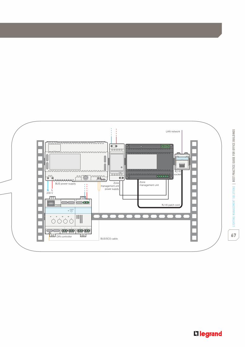
BUS power supply
230 V
DIN controller
Zonemanagement unit
power supply
Zonemanagement unit
RJ 45socket
LAN network
RJ 45 patch cord
BUS/SCS cable

CENTRALIZED MANAGEMENT
68
LIGH
TING
MAN
AGEM
ENT
SOLU
TION
S|
BEST
PRAC
TICE
GUID
EFO
ROF
FICE
BUIL
DING
S
INSTALLATION NOTES1. Design of your project using the software suite Cat.No 488 80. This software allows you to select your detector and controller
products and create your project's architecture. A project database is created with all the components necessary for yourinstallation and the functional links between products.
2. Cabling of the products resulting from your project. The maximum length of each floor bus is 500 m. To extend this limit, itwould be necessary to add extension modules, Cat.No 035 62. The maximum number of circuits for each branch of the bus(associated with the zone management unit) is 175.
3. Power supply to each branch of the bus. Addressing of all products in each branch via the Virtual Configurator softwareconnected to the LAN. The installation is now operational.
4. Adjustment of the detector settings via the mobile configuration tool, Cat.No 882 30.Adjustment of the default detector parameters (delay, sensitivity, mode, lux, calibration).Refer to the technical data sheet for Cat.No 882 30 for more details.
INSTALLATION AND WIRING DETAILS
Cat.No 035 60
230 V
230 V
230 V
Cat.No 035 60
Cat.No 035 60
Cat.No488 44
Cat.No488 22
Cat.No488 44
Cat.No 026 02
Cat.No634 42
Cat.No 026 45
Cat.No802 99
+ RJ 45socket
LAN network3rd floor
2nd floor
RJ 45 patch cord
BUS/SCS
Cat.No 026 02
Cat.No634 42
Cat.No 026 45
Cat.No802 99
+ RJ 45socket
LAN network
RJ 45 patch cord
BUS/SCS
Cat.No488 44
1st floorCat.No 026 02
Cat.No634 42
Cat.No 026 45
Cat.No802 99
+ RJ 45socket
LAN network
RJ 45 patch cordCat.No488 22
Cat.No488 22
BUS/SCS

Ground Floor
69LI
GHTI
NG M
ANAG
EMEN
T SO
LUTI
ONS
|BE
STPR
ACTI
CEGU
IDE
FOR
OFFI
CEBU
ILDI
NGS
CONTROL NEEDS1. Floor scenarios
Certain lighting circuits switched on for the night watchman'sround, according to set timesAll lighting circuits on a floor forced ON and forced OFF whencarrying out lighting maintenanceCorridor lighting circuit switched on if there is at least oneperson present on that floorIllumination of certain glazed outer walls of the buildingaccording to set timesOne lobby circuit remains switched on in the evening from 17:00to 22:00 on working daysCentralised control of meeting rooms from a touch screen
2. MonitoringViewing the status of luminaires throughout the buildingInstant control of presence and the light level in each roomManagement of lamp lifetimes
APPLICATION DESCRIPTIONFloor of 1500 m2, comprising a lobby, two open spaces, conferencerooms and individual officesAll the central controls for the building and the floor are done fromthe office in the lobby
SOLUTION1. Recessed touch screen close to the reception office in the lobby2. Software Pack 3 installed on the lobby office PC3. SCS contact interface4. Key switch

Ground Floor
CENTRALIZED MANAGEMENT
70
LIGH
TING
MAN
AGEM
ENT
SOLU
TION
S|
BEST
PRAC
TICE
GUID
EFO
ROF
FICE
BUIL
DING
S
Configuration software suiteConfiguration for connectingproducts to the BUS/SCS line
Small conferenceroom (p. 5, 9)
Open office(p. 33, 37)
Large private office(p. 25)
Large conference room(p. 13, 17)
Kitchen(p. 29)
Open office(p. 33, 37)
Restroom(p. 57)
Small conferenceroom(p. 5, 9)
Large conferenceroom (p. 13, 17)
Private office(p. 21)
Hallway(p. 45, 49)
Private office(p. 21)
Lobby(p. 53)
Luminaires
Sensors
Room controller(false-ceiling)
71LI
GHTI
NG M
ANAG
EMEN
T SO
LUTI
ONS
|BE
STPR
ACTI
CEGU
IDE
FOR
OFFI
CEBU
ILDI
NGS
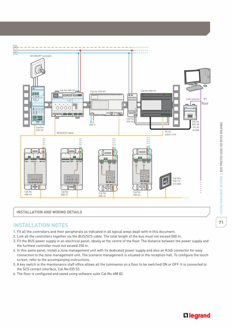
INSTALLATION NOTES1. Fit all the controllers and their peripherals as indicated in all typical areas dealt with in this document.2. Link all the controllers together via the BUS/SCS cable. The total length of the bus must not exceed 500 m.3. Fit the BUS power supply in an electrical panel, ideally at the centre of the floor. The distance between the power supply and
the furthest controller must not exceed 250 m.4. In this same panel, install a zone management unit with its dedicated power supply and also an RJ45 connector for easy
connection to the zone management unit. The scenario management is situated in the reception hall. To configure the touchscreen, refer to the accompanying instructions.
5. A key switch in the maintenance staff office allows all the luminaires on a floor to be switched ON or OFF. It is connected tothe SCS contact interface, Cat.No 035 53.
6. The floor is configured and saved using software suite Cat.No 488 82.
INSTALLATION AND WIRING DETAILS
Cat.No 035 60
230 V
Cat.No 026 02
Cat.No634 42
Cat.No 026 45
Cat.No802 99
+ RJ 45socket
LAN network 1st
floor
RJ 45patch cord
BUS/SCS cable
All ON/OFF scenario
Cat.No035 53
Cat.Nos784 74 /573 960
Cat.No488 47
Cat.No488 43
Cat.No488 42
Cat.No488 42

72
LIGH
TING
MAN
AGEM
ENT
SOLU
TION
S|
BEST
PRAC
TICE
GUID
EFO
ROF
FICE
BUIL
DING
S
CENTRALIZED MANAGEMENT
Ground Floor
EQUIPMENT SCHEDULE
+ All the references quoted:
Use and monitoring of the software is done from the System Utilities and BM Visual software, included in software suite Cat.No 488 82.
Cat.Nos Quantity Description
784 74 1 BUS/SCS multiple scenarios touchscreen control - Mosaic
573 960 1 BUS/SCS multiple scenarios touchscreen control - Arteor
035 60 1 BUS/SCS DIN power supply27 V 1200 mA
492 31/32/33 1 BUS/SCS cable
026 45 1 Zone management unit
634 42 1 BUS/SCS power supply forCat.No 026 45
035 53 1 BUS/SCS DIN contact interface
784 73 1 3-position keyswitch - Mosaic
572 232 1 3-position keyswitch - Arteor
026 45 634 42 784 74

73LI
GHTI
NG M
ANAG
EMEN
T SO
LUTI
ONS
|BE
STPR
ACTI
CEGU
IDE
FOR
OFFI
CEBU
ILDI
NGS
Floor 1 & 2
CONTROL NEEDS1. Floor scenarios
Some lighting circuits switched on to allow the night watchmanto make his roundsThis scenario is selected via a touch screenAll circuits on a floor switched on for cleaning for 1 ½ hoursThis scenario is selected via a touch screenA centralised time switch for shutter control raises all awningsat the end of the day (to prevent any damage in the event of badweather)This scenario is selected via a touch screen
FLOOR REQUIREMENTSFloor of 1500 m2, comprising open spaces, conference rooms,individual offices and corridors.All the central controls for the floor are done by way of a touchscreen located in the maintenance staff's office
APPLICATION DESCRIPTION1500 m2 with corridor, open spaces, individual offices and meetingroom
SOLUTION1. Touch screen2. Zone management unit

74
LIGH
TING
MAN
AGEM
ENT
SOLU
TION
S|
BEST
PRAC
TICE
GUID
EFO
ROF
FICE
BUIL
DING
S
Floor 1 & 2
CENTRALIZED MANAGEMENT
Open office(p. 33)
Private office(p. 21)
Hallway(p. 45)
Private office(p. 21)
Large conferenceroom (p. 13)
Small conferenceroom (p. 5, 9)
Small conferenceroom (p. 5, 9)
Large private office(p. 25)
Large conference room(p. 13)
Kitchen(p. 29)
Open office(p. 33)
Private office(p. 21)
Restroom(p. 57)
Push n' learnConfiguration for connectingproducts to the BUS/SCS line
Luminaires
Sensors
Room controller(false-ceiling)

75LI
GHTI
NG M
ANAG
EMEN
T SO
LUTI
ONS
|BE
STPR
ACTI
CEGU
IDE
FOR
OFFI
CEBU
ILDI
NGS
INSTALLATION NOTES1. Fit all the controllers and their peripherals as indicated. Refer to pages 8, 12, 16, 24, 28, 32, 36, 48 and 60.2. link all the controllers together via the BUS/SCS cable. The total length of the bus must not exceed 500 m.3. Fit the BUS power supply in an electrical panel, ideally at the centre of the floor. The distance between the power supply and
the furthest controller must not exceed 250 m.4. In this same panel, install a zone management unit with its dedicated power supply and also an RJ45 connector for easy
connection to the zone management unit. The scenario management is situated in the corridor on that floor. To configure thetouch screen, refer to the accompanying instructions.
5. In association with the scenario manager, a scenario module situated in the panel on the same floor allows scenarios to becreated without difficulty.
INSTALLATION AND WIRING DETAILS
Cat.No 035 60
230 V
Cat.No634 42
Cat.No 026 45
Cat.No802 99
+ RJ 45socket
LAN network 2nd
floor
RJ 45patch cordBUS/SCS cable
Cat.No035 51
DEL
legrand
035 51
Cat.Nos784 74 /573 960
Cat.No488 47
Cat.No488 43
Cat.No488 42
Cat.No488 42

76
LIGH
TING
MAN
AGEM
ENT
SOLU
TION
S|
BEST
PRAC
TICE
GUID
EFO
ROF
FICE
BUIL
DING
S
CENTRALIZED MANAGEMENT
Floor 1 & 2
EQUIPMENT SCHEDULE
+ All the Catalogue Numbers quoted :
The configuration of all the products must be done without the use of a tool, by manually pressing the learn buttons on each controller, controland sensor. Refer to the push'n learn configuration sheets for more information.This project may be saved, using the Virtual Configurator software.
Cat.Nos Quantity Description
784 74 1 BUS/SCS multiple scenarios touchscreen control - Mosaic
573 960 1 BUS/SCS multiple scenarios touchscreen control - Arteor
035 60 1 BUS/SCS DIN power supply27 V 1200 mA
492 31/32/33 1 BUS/SCS cable
035 51 1 BUS/SCS DIN scenario module
026 45 1 Zone management unit
634 42 1 BUS/SCS power supply forCat.No 026 45
026 45 634 42 784 74

Standards on energy savingsEuropean Standard EN15193 provides a guideline for the energyperformance of lighting systems. Legrand has chosen this standard as abasis to demonstrate the energy performance of its lighting solutions.This standard is widely recognized and provides a calculation methodologyon energy savings according to the type of solution installed, the type ofbuilding and the type of room.
Putting a stop to energy wasteLegrand is commited to providing customers withcomprehensive, transparent information on actualsavings for its lighting management solutions: saving on
Look for this information in our best practiceliteratures.
Green Building programmesGreen Building is an approach to building that considers the overallenvironmental impact of a building as well as the health and well-beingof its occupants.Green Building programmes are voluntary, consensus-based programmesthat provide guidelines. These programmes generally have an associatedrating tool for assessing the environmental performance of the buildingand certifying its compliance with the standard.Green Building certification is awarded to differentiate sustainable buildingprojects and give them credibility. Major Green Building programmes
GREEN STAR.
Mandatory requirements Voluntary programmes
Switch sensors
WHY IMPLEMENT LIGHTING MANAGEMENT ?
230Va.c
Lighting management strategiesLighting management strategies refer to the basic method that will beused to control lighting systems. This will include automatic operation ofthe lighting, taking into account the needs of the space’s occupants :
LIGHTING MANAGEMENT PRODUCTS & SYSTEMS
RELATED SERVICES
Lighting management technologiesLighting management technologies refer to the actual device that willbe used to implement a specific strategy and the method the device willuse to operate (passive infrared, ultrasonic or dual technology sensors,timers or dimmers).
Lighting is a significant consumer of energy in commercial buildings.20% of total site energy is consumed by lighting in commercialbuildings.Lighting is the first electricity end-user in a commercial buildingwith up to 40% electricity consumed*.
Each year, more organisations implement lighting management becausethey recognise its wide range of benefits:
REQUIREMENTS FOR IMPLEMENTING LIGHTING MANAGEMENT
HOW TO IMPLEMENT LIGHTING MANAGEMENT ?
*Energy end-use distribution greatly varies depending on the activity of the building and across geographical and climate regions(Source : Energy Information Administration, USA)
Local supportOur sales representatives are available to assist with all aspects of alighting management projects. Services include building walk-through,training, payback analysis reports and product demonstrations.
Technical supportTelephone technical support from our dedicated team offers personal
guidance for application-related questions, installation assistance ortroubleshooting.
Field servicesFactory-trained assistance during the critical startup and commissioningstages to ensure optimal system performance.Don’t hesitate to contact us.
Our vision at Legrand is to provide products and services that make buildings more energy-efficient.We are committed to ‘putting a stop to energy waste’.
Putting a stop to energy waste
Switch sensors BUS/SCS systems
1 output controls
DIN controllers2 outputs
sensors
software & accessories
room controllers
Radio/Zigbee® accessories
Occupancy-basedcontrol
Scheduledcontrol
Daylightinglevel control
Dimmingcontrol
Vacancy-basedcontrol
PIRtechnology
Ultrasonictechnology
Dualtechnology
Legrand offers two types of solutions and proposes related services to ensure that your lightingmanagement project saves energy and helps the environment.
SAVING ON ENERGY(1)
333 € | year
GREENHOUSE GAS (GHG) EMISSIONS AVOIDED (2)
751 kg | CO2 eq.| year
Legrand lighting management solution for largepartitioned office space – 300 m2 based on:vacancy-based control + daylight-based control
(1) based on EN 15 193
vapour, ozone, carbon dioxide (CO2), methane4), and nitrous oxide (N2O). They are
measured in CO2 equivalent units
Note: A vehicle with an averageconsumption of 4.5 l/100 km emits 11.8 kgof CO2/100 km i.e. 0.118 g of CO2/km
BUS/SCSsystems
Economicsavings
Energysavings
Codecompliance
Sustainabilitybuilding practice

World Headquartersand International Department87045 Limoges Cedex - France
: + 33 (0) 5 55 06 87 87Fax : + 33 (0) 5 55 06 74 55
EXB
0905
0