lighting design process -...
TRANSCRIPT
1
Ball State Architecture | ENVIRONMENTAL SYSTEMS 1 | Grondzik 1
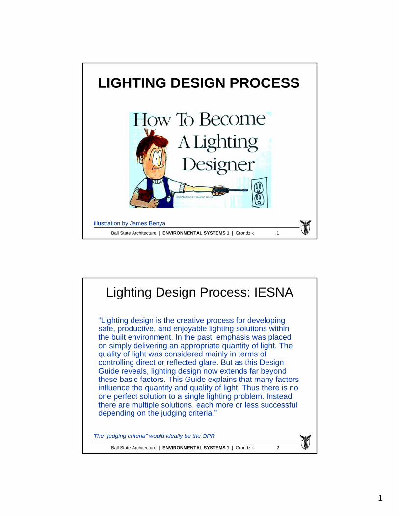
LIGHTING DESIGN PROCESS
illustration by James Benya
Ball State Architecture | ENVIRONMENTAL SYSTEMS 1 | Grondzik 2
Lighting Design Process: IESNA
“Lighting design is the creative process for developing safe, productive, and enjoyable lighting solutions within the built environment. In the past, emphasis was placed on simply delivering an appropriate quantity of light. The quality of light was considered mainly in terms of controlling direct or reflected glare. But as this Design Guide reveals, lighting design now extends far beyond these basic factors. This Guide explains that many factors influence the quantity and quality of light. Thus there is no one perfect solution to a single lighting problem. Instead there are multiple solutions, each more or less successful depending on the judging criteria.”
The “judging criteria” would ideally be the OPR

2
Ball State Architecture | ENVIRONMENTAL SYSTEMS 1 | Grondzik 3
Lighting Design Process: IESNAcontinued …
“And the design must also be appropriate in terms of cost, energy, maintenance, style, availability, and a dozen other considerations. Though not a predictable, linear process, lighting design as revealed by this Guide begins with a concept selected from a myriad of alternatives. Then, as the process proceeds, it is filled with cross-checking. Like many architectural projects, most lighting designs can be circumscribed by the following seven-step process: Programming, Schematic Design, Design Development, Contract Documents, Bidding and Negotiation, Construction, and Post-occupancy Evaluation. These elements are discussed in full detail in this Guide.”
Illuminating Engineering Society of North America
Ball State Architecture | ENVIRONMENTAL SYSTEMS 1 | Grondzik 4
Lighting Design Process: Lam
“A new process of design …
This is the diametric opposite of the typical ‘engineered’ approach, which starts with the selection of light fixtures and then, taking them as givens, places them in patterns to achieve predetermined illumination levels.”
William Lam
Perception and Lighting as Formgivers for Architecture
3
Ball State Architecture | ENVIRONMENTAL SYSTEMS 1 | Grondzik 5
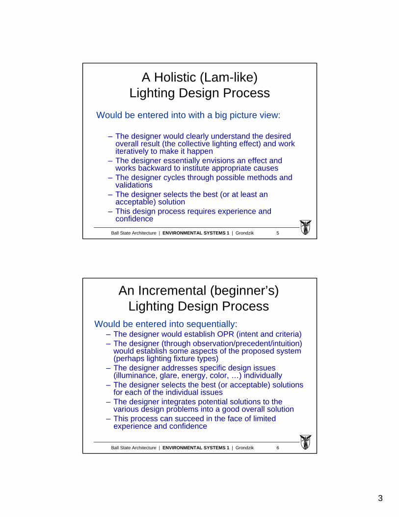
A Holistic (Lam-like)Lighting Design Process
Would be entered into with a big picture view:
– The designer would clearly understand the desired overall result (the collective lighting effect) and work iteratively to make it happen
– The designer essentially envisions an effect and works backward to institute appropriate causes
– The designer cycles through possible methods and validations
– The designer selects the best (or at least an acceptable) solution
– This design process requires experience and confidence
Ball State Architecture | ENVIRONMENTAL SYSTEMS 1 | Grondzik 6
An Incremental (beginner’s)Lighting Design Process
Would be entered into sequentially:– The designer would establish OPR (intent and criteria)– The designer (through observation/precedent/intuition)
would establish some aspects of the proposed system (perhaps lighting fixture types)
– The designer addresses specific design issues (illuminance, glare, energy, color, …) individually
– The designer selects the best (or acceptable) solutions for each of the individual issues
– The designer integrates potential solutions to the various design problems into a good overall solution
– This process can succeed in the face of limited experience and confidence

4
Ball State Architecture | ENVIRONMENTAL SYSTEMS 1 | Grondzik 7
Some Design Issues to Consider
issues considered very important in an office with computers are flagged
Ball State Architecture | ENVIRONMENTAL SYSTEMS 1 | Grondzik 8
Some Design Issues … cont’d
other s
pace types

5
Ball State Architecture | ENVIRONMENTAL SYSTEMS 1 | Grondzik 9
Following the Incremental Trail …
Let’s look, in more detail, first at:
Illuminance (a “quantity”)
and then
Glare (a “quality”)
Ball State Architecture | ENVIRONMENTAL SYSTEMS 1 | Grondzik 10
Illuminances to be Considered
• Design illuminance (DI)– The design criterion (a target; defines success)
• Initial illuminance (II)– Illuminance at the time the lighting system is
first used (at the start of owner occupancy)
• Maintained illuminance (MI)– Illuminance after some defined time (typically
several years) of usage; after wear and tear takes a toll on the system
MI must be >= DI II will be > DI
6
Ball State Architecture | ENVIRONMENTAL SYSTEMS 1 | Grondzik 11
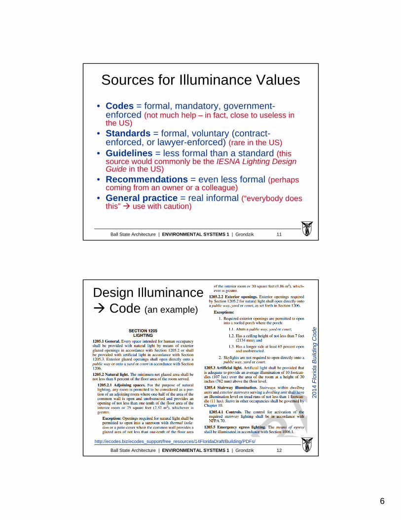
Sources for Illuminance Values
• Codes = formal, mandatory, government-enforced (not much help – in fact, close to useless in the US)
• Standards = formal, voluntary (contract-enforced, or lawyer-enforced) (rare in the US)
• Guidelines = less formal than a standard (this source would commonly be the IESNA Lighting Design Guide in the US)
• Recommendations = even less formal (perhaps coming from an owner or a colleague)
• General practice = real informal (“everybody does this” use with caution)
Ball State Architecture | ENVIRONMENTAL SYSTEMS 1 | Grondzik 12
Design Illuminance Code (an example)
http://ecodes.biz/ecodes_support/free_resources/14FloridaDraft/Building/PDFs/
2014
Flo
rida
Bui
ldin
g C
ode

7
Ball State Architecture | ENVIRONMENTAL SYSTEMS 1 | Grondzik 13
Design Illuminance Code
Florida Building Code (2014)
SECTION 1205: LIGHTING
Comments: although compliance with codes is mandatory, there is not much in this code section to truly inform design beyond a specific minimum illuminance for emergency conditions;
Terminology is awkward: “natural” and “artificial”
The specified minimum non-emergency illuminance (107 lux or 10 fc) would be quite unacceptable to most owners/users in many common space types
Codes are not written to ensure satisfaction—but to ensure life safety
Ball State Architecture | ENVIRONMENTAL SYSTEMS 1 | Grondzik 14
Design Illuminance Guideline
room/task-specificilluminance values;generally above the
107 lux code minimum
see next slide

8
Ball State Architecture | ENVIRONMENTAL SYSTEMS 1 | Grondzik 15
DesignIlluminancesGuideline
Illuminance categories
From IESNA LightingHandbook (9th edition)
code
s m
ay
cont
rol
perf
orm
ance
nee
dsw
ill c
ont
rol
Note: the 10th (current) edition of the IESLighting Handbook substantially revised the design illuminance selection information; this older table is shown here because the concept is similar and the information is easier to digest.
Ball State Architecture | ENVIRONMENTAL SYSTEMS 1 | Grondzik 16
DesignIlluminances
contrast andtask size…with judgment
eye condition (age) ?
task speed ?
validation ?… and judgment
Addressing …
base
d u
pon
visu
al a
cuity
tem
pere
d b
y
proj
ect s
peci
fics
9
Ball State Architecture | ENVIRONMENTAL SYSTEMS 1 | Grondzik 17
A Comment on Illuminances
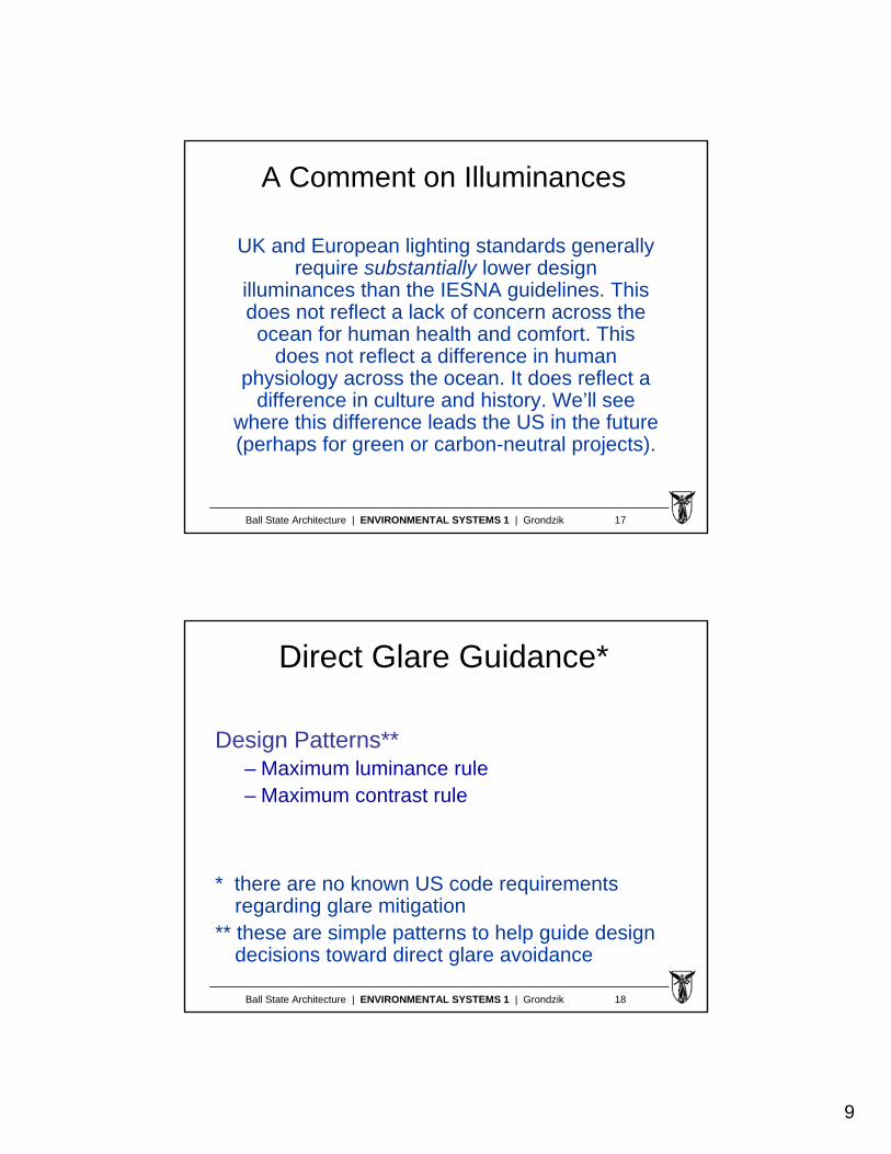
UK and European lighting standards generallyrequire substantially lower design
illuminances than the IESNA guidelines. Thisdoes not reflect a lack of concern across theocean for human health and comfort. This
does not reflect a difference in humanphysiology across the ocean. It does reflect a
difference in culture and history. We’ll seewhere this difference leads the US in the future (perhaps for green or carbon-neutral projects).
Ball State Architecture | ENVIRONMENTAL SYSTEMS 1 | Grondzik 18
Direct Glare Guidance*
Design Patterns**– Maximum luminance rule– Maximum contrast rule
* there are no known US code requirements regarding glare mitigation
** these are simple patterns to help guide design decisions toward direct glare avoidance
10
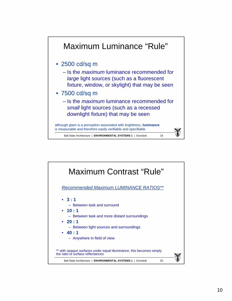
Ball State Architecture | ENVIRONMENTAL SYSTEMS 1 | Grondzik 19
Maximum Luminance “Rule”
• 2500 cd/sq m – Is the maximum luminance recommended for
large light sources (such as a fluorescent fixture, window, or skylight) that may be seen
• 7500 cd/sq m – Is the maximum luminance recommended for
small light sources (such as a recessed downlight fixture) that may be seen
although glare is a perception associated with brightness, luminanceis measurable and therefore easily verifiable and specifiable
Ball State Architecture | ENVIRONMENTAL SYSTEMS 1 | Grondzik 20
Maximum Contrast “Rule”
Recommended Maximum LUMINANCE RATIOS**
• 3 : 1– Between task and surround
• 10 : 1– Between task and more distant surroundings
• 20 : 1– Between light sources and surroundings
• 40 : 1– Anywhere in field of view
** with opaque surfaces under equal illuminance, this becomes simply the ratio of surface reflectances

11
Ball State Architecture | ENVIRONMENTAL SYSTEMS 1 | Grondzik 21
A Numeric Index for Direct Glare
Visual Comfort Probability (VCP)– VCP represents the percentage of occupants who,
when using a space as intended, would say that they do NOT sense direct glare
– 70 or greater is considered a “good” value– VCP varies from lighting design to lighting design;
and from location to location within a given space– Can be “measured” in an occupied space (as a POE
tool) or simulated using computers (as a design tool)– Generic data are provided by some electric luminaire
manufacturers for typical room layouts (but not by window manufacturers for daylighting)
Ball State Architecture | ENVIRONMENTAL SYSTEMS 1 | Grondzik 22
Reflected Glare “Rules”
The “common sense” geometry rule (which involves identifying the “offending zone”)
– Look at the geometry of tasks and lighting elements during design and avoid potentially poor design decisions involving reflective surfaces (see next slide)
12
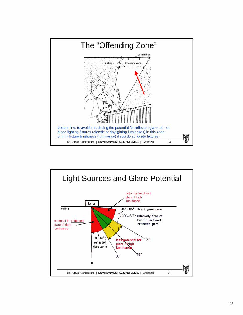
Ball State Architecture | ENVIRONMENTAL SYSTEMS 1 | Grondzik 23
The “Offending Zone”
bottom line: to avoid introducing the potential for reflected glare, do not place lighting fixtures (electric or daylighting luminaires) in this zone;or limit fixture brightness (luminance) if you do so locate fixtures
Ball State Architecture | ENVIRONMENTAL SYSTEMS 1 | Grondzik 24
Light Sources and Glare Potential
potential for reflectedglare if highluminance
potential for directglare if highluminance
less potential forglare if highluminance
ceiling

13
Ball State Architecture | ENVIRONMENTAL SYSTEMS 1 | Grondzik 25
Two Numeric Indices for Reflected Glare
• Contrast rendition factor (CRF)
• Equivalent spherical illuminance (ESI)
Ball State Architecture | ENVIRONMENTAL SYSTEMS 1 | Grondzik 26
Contrast Rendition Factor (CRF)
• CRF is the ratio of contrast at a task under a proposed (or given) lighting system to the contrast under a reference spherical (“glare-free”) lighting system Cprop/Cref
• CRF could possibly range from 1.0 to 0.0• The higher the CRF the better (with respect to
reflected glare potential)• No generally-accepted design standards or
guidelines for appropriate CRF values are currently available
14
Ball State Architecture | ENVIRONMENTAL SYSTEMS 1 | Grondzik 27
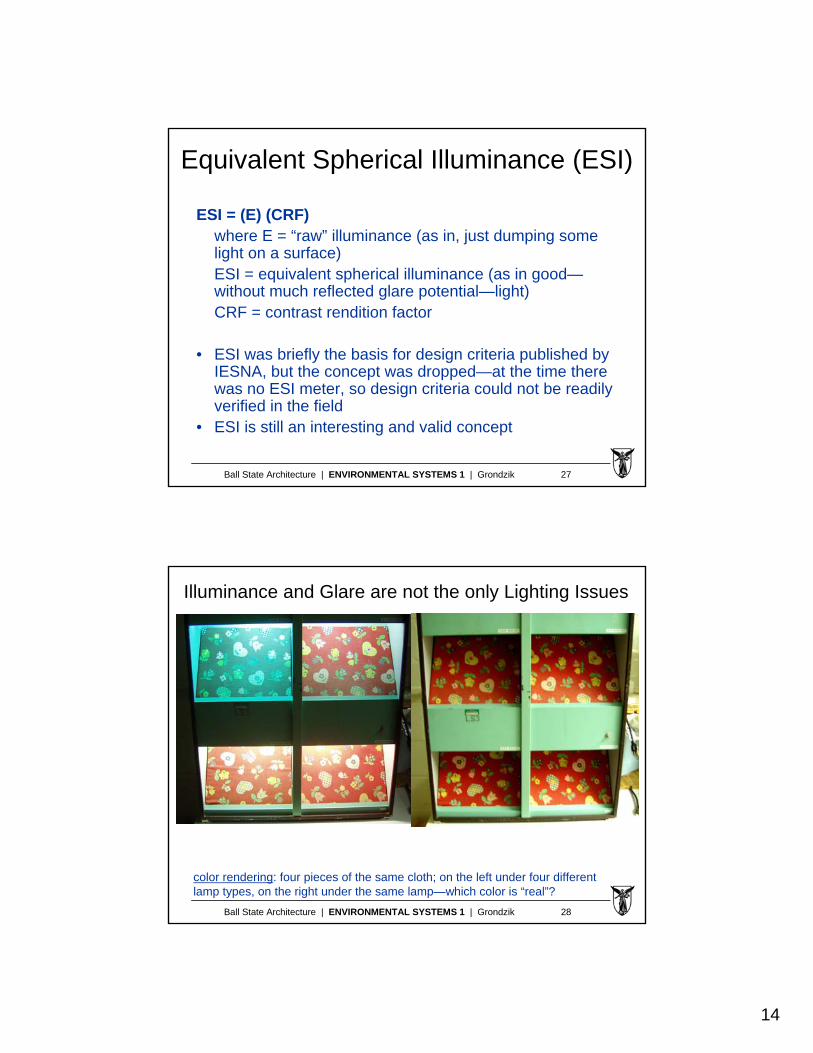
Equivalent Spherical Illuminance (ESI)
ESI = (E) (CRF)where E = “raw” illuminance (as in, just dumping some light on a surface) ESI = equivalent spherical illuminance (as in good—without much reflected glare potential—light) CRF = contrast rendition factor
• ESI was briefly the basis for design criteria published by IESNA, but the concept was dropped—at the time there was no ESI meter, so design criteria could not be readily verified in the field
• ESI is still an interesting and valid concept
Ball State Architecture | ENVIRONMENTAL SYSTEMS 1 | Grondzik 28
color rendering: four pieces of the same cloth; on the left under four differentlamp types, on the right under the same lamp—which color is “real”?
Illuminance and Glare are not the only Lighting Issues

15
Ball State Architecture | ENVIRONMENTAL SYSTEMS 1 | Grondzik 29
energy use for lighting: in residences (left) and offices (right)–the first best design moves are building-type specific
Energy and Environmental Impactare also Lighting Design Issues