light oil burners · 2014-08-08 · light oil burners . index maior p 500.1 maior p 600.1...
TRANSCRIPT
EN
MAIOR P 500.1 PR TC 230-400-50 3121049
MAIOR P 500.1 PR TL 230-400-50 3121050
MAIOR P 600.1 PR TC 230-400-50 3121051
MAIOR P 600.1 PR TL 230-400-50 3121052
Technical data
Operating instructions
Electric diagrams
Spare parts list
MAIOR P 500.1 PR
MAIOR P 600.1 PR
www.ecoflam-burners.comLIGHT OIL BURNERS
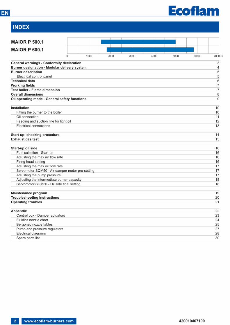
INDEX
MAIOR P 500.1
MAIOR P 600.1
420010467100
EN
www.ecoflam-burners.com2
General warnings - Conformity declaration 3
Burner designation - Modular delivery system 4
Burner description 5
Electrical control panel 5
Technical data 6
Working fields 7
Test boiler - Flame dimension 7
Overall dimensions 8
Oil operating mode - General safety functions 9
Installation 10
Fitting the burner to the boiler 10
Oil connection 11
Feeding and suction line for light oil 12
Electrical connections 13
Start-up: checking procedure 14
Exhaust gas test 15
Start-up oil side 16
Fuel selection - Start-up 16
Adjusting the max air flow rate 16
Firing head setting 16
Adjusting the max oil flow rate 17
Servomotor SQM50 - Air damper motor pre-setting 17
Adjusting the pump pressure 17
Adjusting the intermediate burner capacity 18
Servomotor SQM50 - Oil side final setting 18
Maintenance program 19
Troubleshooting instructions 20
Operating troubles 21
Appendix 22
Control box - Damper actuators 23
Fluidics nozzle chart 24
Bergonzo nozzle tables 25
Pump and pressure regulators 27
Electrical diagrams 28
Spare parts list 30
0 1000 2000 3000 4000 7000 kW5000 6000

GENERAL WARNINGS - CONFORMITY DECLARATION
MAIOR burners are designed for
the combustion of light oil.
The design and function of the burners
meet the standard EN267. They are
suitable for use with all heat generators
complying with standard within their
respective performance range.
Any other type of application requires the
approval of ECOFLAM.
Installation, start-up and maintenance
must only be carried out by authorised
specialists and all applicable guidelines
and regulations must be complied with.
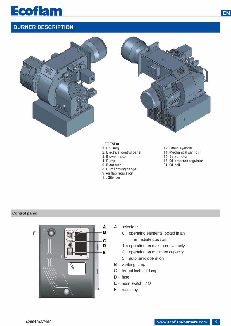
BURNER DESCRIPTION
MAIOR burners are progressive
mechanical fully automatic monoblock
devices.
Emissions values may differ, depending on
combustion chamber dimensions,
combustion chamber load and the firing
system (three-pass boilers, boilers with
reverse firing).
PACKAGING
The burner, and all the additional
components are supplied in a modular
system of packages according to the
configuration ordered that based on the
country of installation shall follow the
applicable standards and the local rules
and code of practise.
The following standards should be
observed in order to ensure safe,
environmentally sound and energy-efficient
operation:
EN 267Automatic forced draught burners for liquidfuels.
EN 60335-1, -2-102
Specification for safety of household and
similar electrical appliances, particular
requirements for gas burning appliances
INSTALLATION LOCATION
The burner must not be operated in rooms
containing aggressive vapours (e.g. spray,
perchloroethylene, hydrocarbon
tetrachloride, solvent, etc.) or tending to
heavy dust formation or high air humidity.
Adequate ventilation must be provided at
the place of installation of the furnace
system to ensure a reliable supply with
combustion air.
!BURNER SELECTION: Type of operation and configuration must be done by professional personnel in order to grant correct working of the
burner. Installation, start-up and maintenance must be carried out by authorised specialists and all applicable guidelines and regulations
(including local safety regulations and codes of practise) must be observed.
We accept no responsibility for
damage arising from:
- inappropriate use;
- incorrect installation and/or repair on
the part of the buyer or any third party,
including the fitting of non-original parts;
- non authorised modifications made
on the burner.
Final delivery and instructions for use
The firing system installer must supply
the operator of the system with operating
and maintenance instructions on or before
final delivery. These instructions should
be displayed in a prominent location at the
point of installation of the heat generator,
They should include the address and
telephone number of the nearest customer
service centre.
Notes for the operator
The system should be inspected by a
specialist at least once a year.
Depending on the type of installation,
shorter maintenance intervals may be
necessary.
It is advisable to take out a maintenance
contract to guarantee regular servicing.
Ecoflam burners have been designed and built in compliance with all current regulations
and directives.
All burners comply to the safety and energy saving operation regulations within the standard
of their respective performance range. The quality is guaranteed by a quality and management
system certified in accordance with ISO 9001:2008.
Declaration of conformity
for dual fuel burners
We,
Ecoflam Bruciatori S.p.A.
declare under our sole responsibility
that the products:
MAIOR P 500.1 PR
MAIOR P 600.1 PR
conform to the following standards:
EN 267: 2010
EN 60335-1: 2008
EN 60335-2-30: 2006
EN 60335-2-102: 2007
EN 55014-1: 2008 + A1: 2009
EN 55014-2: 1998 + A1: 2001 + A2: 2008
These products are built in accordance
with the following directives
2006/42/EC Machinery directive
2004/108/EC EMC directive
2006/95/EC Low voltage directive
CE certification, when required, must be
done at installation site by the end user
Resana, 20th December 2010
M. PANIZZON
420010467100
EN
www.ecoflam-burners.com 3

BURNER DESIGNATION
MAIOR P 300.1 PR TC 230-400-50
MAIOR Light oil
RANGE NAME BY FUEL TYPE
MAIOR P 300.1 253 kg/h - 3000 kW
MODEL SIZE (Gas: kW; Oil: kg/h)
- Standard Class 1 - OIL EN267 (<250 mg/kWh)
EMISSIONS
PR 2 stages progressive mechanical gas / oilMD 2 stages modulating mechanical with PIDE 2 stages modulating electronic
OPERATION TYPE
TC Short headTL Long head
HEAD TYPE
Light oil BIODIESEL BiodieselKEROSENE Kerosene
FUEL
420010467100
EN
www.ecoflam-burners.com4
230-400V/50Hz 230-400 Volt, 50 Hz
ELECTRICAL POWER SUPPLY
MODULAR DELIVERY SYSTEM
Light oil burners
All light oil burners are delivered complete in one single packaging including filter and
flexible hoses up to 6 MW.
Additional accessories and options shall be installed by the installer in accordance to the
instruction and local safety regulations and codes of practise.
KITS - Accessories
Kits and accessories are managed and delivered separately.
Component type
CB Complete burner
KIT Kits
ACS Accessories
BURNER DESCRIPTION
Control panel
420010467100
EN
www.ecoflam-burners.com 5
AB
C
E
D
F0
AUTO
0I
A - selector :
0 = operating elements locked in an
intermediate position
1 = operation on maximum capacity
2 = operation on minimum capacity
3 = automatic operation
B - working lamp
C - termal lock-out lamp
D - fuse
E - main switch I / O
F - reset key
LEGENDA
1. Housing
2. Electrical control panel
3. Blower motor
4. Pump
6. Blast tube
8. Burner fixing flange
9. Air flap regulation
11. Silencer
12. Lifting eyebolts
14. Mechanical cam oil
15. Servomotor
18. Oil pressure regulator
21. Oil coil
14
21
18
1
8
12
1
9
11
3
2
4
15

6 www.ecoflam-burners.com
EN
420010467100
TECHNICAL DATA
MODEL MAIOR P 500.1 MAIOR P 600.1
Thermal power max.
kW 5.000 5.800
kcal/h 4.300.000 4.988.000
kg/h 422 489
Thermal power min.
kW 1.200 1.500
kcal/h 1.032.000 1.290.000
kg/h 101 126
Operation mode Type Progressive mechanical oil - Modulating with PID
Regulation ratio nominal Type 1÷3 OIL
Fuel Type Light oil (L.C.V. 10.200 kcal/kg max. visc 1,5°E at 20°C) - EL) Hu = 11,86 kWh/kg
Emission class std Standard Class 1 OIL EN267 (<250 mg/kWh)
Control unit Type LAL
Air regulation Type Air flap Air flap
Air flap control with servomotor Model SQM50
Flame monitoring Type photoresistor
Ignitier Model BRAHMA
Motor kW 11 15
Rpm N° 2.800 2.800
Voltage V/Hz 230/400 V - 50 Hz
Total power consumption operation W 12.000 16.500
Weight body BBCH Kg
Electrical panel protection level IP IP40 IP40
Sound pressure level without silencer
dB(A)
Lab
tests
91,1 92,8
Sound pressure level with silencer
85,7 86,7
Ambient temperature storageMin/Max
-20°…+70° C
Ambient temperature use -10°…+60° C
Oil pump Model TA3 TA4
Oil pump motor kW 0,74 kW 1,1 kW
Nozzles Type according to the output requested

0
5
10
15
20
25
1000 2000 3000 4000 5000 6000 7000
1000 2000 3000 4000 5000 6000
100 200 300 400 500
mbar
kW
kg/h
kcal/h*1000
MAIOR P 500.1
MAIOR P 600.1
7www.ecoflam-burners.com
EN
420010467100
WORKING FIELDS
TEST BOILER - FLAME DIMENSIONS
The burner/boiler matching does not pose
any problem if the boiler is CE type-
approved.
If the burner must be combined with a
boiler that has not been CE type-approved
and/or its combustion chamber dimensions
are clearly smaller than those indicated in
diagram, consult the manufacturer.
The firing rates were set in relation to
special test boilers, according to EN 267
regulations.
The sizes are indicative and dipend on
the configuration, to the combustion
chamber pressure and to the draught.
The values have been taken out from
tests executed with flame tubes.
The dimensions of the flame are made
in test boiler in laboratory without
resistence therefore exists max and
min lenght that take into account the
difference in lenght that comes from the
boiler backpressure.
Example:
Burner thermal output = 8000 kW;
L flame (m) = 5 m (medium value)
D flame (m) = 1 m (medium value)
WARNING: Some flame modifications
can be done in our FLEXSHOP in the
factory in order to shape the flame and
adapt it to some special boiler
or application.
L (m)
2000 3000 4000 5000 6000 7000 8000 9000 10000
4
5
1000
2000 30001000
6
11000
0
2
3
7
8
12000 kW13000
9
10
11
kg/h100 200 300 400 500 600 700 800 900 1000 1100
kcal/hx 10004000 5000 6000 7000 8000 9000 10000 11000 12000 13000 14000 15000
14000 15000 16000 17000
1200 1300 1400
Ø (m)
2000 3000 4000 5000 6000 7000 8000 9000 10000
0,6
0,8
1000
2000 30001000
1
11000
0
0,2
0,4
1,2
1,4
12000 kW13000
1,6
1,8
2
kg/h100 200 300 400 500 600 700 800 900 1000 1100
kcal/hx 10004000 5000 6000 7000 8000 9000 10000 11000 12000 13000 14000 15000
14000 15000 16000 17000
1200 1300 1400
FLAME LENGHT LIGHT OIL BURNERS
FLAME DIAMETER LIGHT OIL BURNERS
Working fields
The working field shows burner
output as a function of
combustion chamber pressure.
It corresponds to the maximum
values specified by EN 276
measured at the test fire tube.
Boiler efficiency should be
taken into consideration when
selecting the burner.
Calculation of
burner output
QF = Burner output (kW)
QN = Rated boiler output(kW)
η = Boiler efficiency (%)
QF = QN x 100η

IM
L
E D - D1
F
G
CBA
HSUNTECSUNTECSUNTEC
8 www.ecoflam-burners.com
EN
420010467100
OVERALL DIMENSIONS
Dimensions (mm)
D = Short head
D1= Long head
A B C D D1 E F G H1 I L M
MAIOR P 500.1 1180 535 645 355 555 970 320 570 965 330 330 M16
MAIOR P 600.1 1190 545 645 355 555 970 320 570 965 330 330 M16
Fixing hole dimensions are “I” and “L” as per dimension table.
Boiler hole shall be done according to the blast tube dimension “F” plus
15-25 mm in order to be able to extract it during maintenance.
Burner-boiler mounting flange
Packaging (only burner)
WARNING: Please follow the suggested dimension for the hole on
the boiler flange in order to fit the burner. Make sure that between the boiler and
the blast tube proper insulation is fitted.
X Y Z kg
MAIOR P 500.1 PR 1575 1575 1040
MAIOR P 600.1 PR 1575 1575 1040
X Y
Z
330
420
330
420

9www.ecoflam-burners.com
EN
420010467100
OIL OPERATING MODE - GENERAL SAFETY FUNCTIONS
GENERAL SAFETY FUNCTIONS
In case a flame does not develop when
starting the burner (fuel release) the
burner will shut off at the end of the safety
period (safety lock-out).
A safety lock-out will also occur in the case
of flame failure during operation, air flow
failure during the pre-ventilation phase and
pressure failure during the whole period of
burner operation.
Any failure of the flame signal at the end of
the safety period and a flame signal during
the pre-ventilation phase (external light
control) will result in a safety lock-out with
the control box being locked.
The trouble is indicated by the trouble
signal lamp lighting up.
The control box can be unlocked
immediately after a safety lock-out by
pressing the unlocking key. The program
unit will return to its starting position and
proceed with the restart of the burner.
A voltage failure will result in a regular
shut-off of the burner. Upon voltage
recovery there may be an automatic
restart unless another interlock is
provided, e.g. by the safety system. In any
case of trouble the fuel oil supply will be
shut off right away. The program unit will
stop at the same time causing also the
trouble location indicator to stop.
The symbols will indicate the kind of
trouble.
START-UP MODE
As soon as the furnace system is required
to supply heat the burner control circuit will
close and the program be started. After the
program has run down the burner will start.
The air damper is closed when the burner
iis out of operation.
The automatic furnace controller controls
and monitors the starting function.
The electric actuator opens the closed air
damper to its full-load position so that the
burner will sweep the furnace
compartment and exhaust ports at the
required air flow rates. At the end of the
specified pre-ventilation time the air
damper will be moved into its partial load
position. This operation will be followed by
the pre-ignition procedure and the oil feed
start.
The solenoid valves will open and thus
allow the pressurized oil to flow to the
nozzle and to the return line.
The oil will be atomized, mixed with the
combustion air and ignited.
A safety period is provided to allow the
flame to develop a proper and steady
pattern.
On the termination of the safety period, a
flame signal must have been received by
the automatic furnace controller via the
flame monitor and remain on until the
regular shut-off.
The startup program of the burner has now
been completed.
OIL OPERATING MODE
After the flame has developed the load
regulator will be enabled which brings the
burner into its operating position.
The load regulator will now control the
burner automatically between its partial-
load and full-load stages.
Depending on the heat demand, the
electric actuator of the mechanical
compound control system will be fed with
the OPEN or CLOSE signal via the
regulator and thus increase or decrease
the oil and air flow rates.
This compound control system will vary
the positions of the oil control valve and air
damper and thus regulate the oil flow rate
in conjunction with the air flow rate. The
burner can either be controlled in two-
stage sliding mode or, if a respective
controller is provided, in stepless control
mode.
The stepless control will allow the burner
to be operated at any desired stage
between its partial-load and full-load
positions. The burner will be turned off
from its partial-load position. The air
damper will be closed when the burner is
out of operation and will thus prevent cold
air flowing through the burner chamber,
heat exchanger and chimney.
The interior cooling losses will be greatly
minimized.
Zündung/VentilePumpe
Teillast
EIN
Betriebsstellung
Leistungsregulierung
Freigabe
Vollast
AUS
Zündung/VentilePumpe
Teillast
EIN
Freigabe
Leistungsregulierung
Betriebsstellung
Vollast
AUS
Oil control:
2-stage sliding Stepless
Full load
Operating position
Load regulator
Release
Partial load
Ignition/valvesPump
Full load
Operating position
Load regulator
Release
Partial load
Ignition/valvesPump
ON OFF ON OFF

5÷6 mm
3÷4 mm
! WARNING: handling and moving operations must be carried out by specialised personnel.Use the eyebolts to lift the burner in order that it will not overturn and fall down.
INSTALLATION
Fitting the burner to the boiler
To perform the installation of the burner
into the boiler drill the boiler plate
according to the dimension given on this
manual and place the burner towards it by
lifting and moving the burner by means of
eyebolts.
Place the gasket on the burner flange and
install the burner into the boiler by fixing
nuts into the bolts.
The space between the blast tube and the
boiler lining must be sealed with
appropriate insulating material.
Position of the electrodes - nozzle installation
Ignition Electrode
BURNER LINING
Check before burner installation:
1. Depending on the type of boiler (reverse flame or three
pass) check the burner blast tube installation depth
according to the data specified by the boiler manufacturer or
consult the burner producer.
2. From the factory the nozzle for progressive version must
be specified from the customer according to boiler output and
combustion chamber geometry, otherwise we will select the
nozzle for the 80% capacity of the burner.
3. Check the ignition electrodes and the nozzle on the burner
head as per factory setting (see figures).
The setting of the mixing and ignition unit according to the
boiler output will be performed during commissioning
procedure.
4. Check that the head is preset at 50%.
420010467100
EN
www.ecoflam-burners.com10
0IMAIN SWITCH
0 - OFF
1 - ON

! WARNING: make sure that the feeding line is properly dimensioned and is in compliance with the local safety rules and code of practise in the country of installation
INSTALLATION
Oil connection
HYDRAULIC CIRCUIT
LIGHT OIL FEEDING
176: oil pump
178: solenoid valve
184: output control valve
311: return oil pressure switch
CV: check valve
RL: return line
VL: suction line
VLO: working oil valve
VLO
311
178176
CV
184
VL
RL
OIL PRESSURE CONTROL (FEED)
The feed pressure is controlled by means
of the pressure regulator installed in the
pump and should be set at 25 bar. The
pressure regulator is operated by turning
its screw. Make sure to fill the pump with
oil prior to taking into operation.
PUMP BLEEDING
Open the feed and return stop valves and
ensure the ring line (if any) is in operation.
Reduce the oil pressure at the pressure
regulating valve. Turn on the pump by
pressing the contactor.
Check the pump for proper direction of
rotation. Check for proper oil delivery and
absence of leaks in the hydraulic oil
system. For bleeding the pump open the
pressure gauge connection, for example.
When taking the burner into operation pro
ceed by gradually increasing the pressure
to operating level (25 bar).
CHECKING THE PRESSURE
(OIL SUCTION PRESSURE)
The maximum permissible vacuum is 0,4
bar. At higher vacuum levels the fuel oil will
tend to separate air from oil which may
lead to operating trouble. In the ring line
mode of operation the recommended oil
pressure is 2 bar.
OIL CONNECTION
Hoses are used for connection to the oil
lines and stop valves. The hoses must be
installed according to the applicable
standards (relieved of tensile load, free of
distortion) to avoid kinking and exclude the
danger of breakage. Take care when
mounting the oil lines to bring their ends as
close to the burners as possible and to
arrange them in a way that the boiler door
and the burner can be swing out without
any obstruction.
Refer to the technical documentation for
the line dimensions for the feed and return
lines from the stop valves to the tank.
OIL FILTER
A filter must be installed upstream of the
pump to protect the oil pressure pump and
the hydraulic system.
INSTALLATION OPTIONS
• Two-line installation (separate feed and
return lines without delivery pump).
• Ring line system (with delivery pump and
gas-air separator).
LEGENDA
1. Inlet
2. Return
3. Bleed and pressure gauge port
4. Vacuum gauge port
5. Pressure adjustment
6. Nozzle outlet
7. Heater
8. Hose
9. Oil filter
10. Oil ball valve
! WARNING: Check that the pump rotation is correct and before start up it has been pre-filled
8
8
9
10
420010467100
EN
www.ecoflam-burners.com 11

INSTALLATION
The pumps that are used can be installed both into single-pipe and
double-pipe systems:
Single-pipe system: a single pipe drives the oil from the tank to the pump’s
inlet that deliver the pressurized oil to the nozzle and part of the oil not used
goes back to the pump. With this single pipe the by-pass plug must be
removed and the return port must be sealed with steel plug and washer.
Double-pipe system: this is the default solution from the factory.
The return pipe send the excess oil from the pump to the tank. Depending
on the type of pump used to change from a 1-pipe system to a 2-pipe-
system, insert the by-pass plug (as for ccw-rotation referring to the pump
shaft).
Note for commissioning: during commissioning, the filter, pipelines and
pumps must be pre-filled with fuel oil and vented.
The direction of rotation of the motor should be checked. When
commissioning it must be ensured that pump never run dry.
SUNTEC TA
NOZZLE SELECTION
Please refer to diagram to select Ecoflam recommended nozzle for the
output that is required given the output necessary in the installation.
Regular maintenance is highly recommended.
Nozzle has to be cleaned in petrol or paraffin and if filter or other parts are
defective or
damaged the nozzle must be replaced.
NOZZLE CHART IS AVAILABLE ON APPENDIX PAGE
Oil under suction
Oil under pressure Pressuregauge port
To nozzle
Pressureadjustment
By-passplug
inserted
By-passplug
removed
Return
Intake from Tank
TWO PIPEINSTALLATION
Vacuum orinlet pressure
gauge portBy-passed oilreturned to tank,or to suction
Intake from Tank
ONE PIPEINSTALLATION
Returnplugged
420010467100
EN
www.ecoflam-burners.com12
Feeding and suction line for light oil
SUCTION LINE LENGTHS FOR PIPE SYSTEMS
• Two-pipe siphon feed system
H
H
The burner is equipped with a self-priming pump which is capable of feeding
itself within the limits listed in the table at the side.
• Two-pipe lift system
WARNING: To calculate the length of the pipework all the straight parts, curves, up and down pipes must be taken into consideration.
The static suction height is the distance between the standing valve and the axis of the burner pump.
Negative pressure must not exceed 0,45 bar; if negative pressure is greater pump operation may become faulty, leading to an increase
in mechanical noise and perhaps even breakage.
All oil ring installations must comply with the local safety rules existing in the country of installation
H
(m)
PIPE LENGTH (m)
TA3 TA4
ø 14 mm ø 16 mm ø 20 mm ø 20 mm ø 30 mm
3 10 32 115 65 150
2,5 8 28 110 60 150
2 7 25 100 55 150
1,5 6 22 95 50 150
1 5 20 85 45 150
0,5 -- 17 75 40 150
0 -- 15 65 35 150
-0,5 -- 10 55 28 150
-1 -- 5 45 22 150
-1,5 -- -- 37 12 150
-2 -- -- 30 7 150
-2,5 -- -- 22 -- 150
-3 -- -- 9 -- 123
-3,5 -- -- -- -- 78
-4 -- -- -- -- 38

13www.ecoflam-burners.com
EN
420010467100
INSTALLATION
Electrical connections
! WARNING: Electrical wiring must be carried out with electrical supply disconnected and with burner switch in position OFF.Electrical supply must correspond to the one shown on the burner label.
APPLICABLE STANDARD
The electrical connection work comprising
all the installation materials, terminals and
earth connections must be carried out in
accordance with the applicable
regulations. For the electrical installation of
the burner care must be taken to observe
the circuit diagram made out for the
furnace system.
The electrical connection of the burner and
instruments shall be entrusted to
authorized specialists only.
NOTE: For the installation of the
connection cables care must be taken to
provide cable loops of sufficient length to
allow for the swing-out of the boiler door
and burner.
Make sure after the completion of the
electrical connection work to check the
wiring of the electrical system of the
burner. This should include a check of the
direction of rotation of the burner motor
(fan).
GENERAL WARNINGS:
All applicable electrical safety regulations
must be followed. Failure to correctly
dimension the suitable input power and
earth the equipment may cause damages
to person and compromise the correct
function of the burner therefore the
electrical system shall be checked by
qualifed personnel.
The manufacturer declines all
responsibility for modifcations or
connections different from those shown in
the electrical scheme.
Adapters, multiple plugs and extension
cables may not be used for the
equipment’s power supply.
An omnipolar switch in accordance with
current safety regulations is required for
the mains supply connection.
ELECTRICAL CONNECTION
1) of the burner
- Built-in electrical cabinet
Use cable gland in order to secure the
required level of protection. All the links,
power and control, are connected to the
terminal block of the cabinet. Provide
cables in sufficient length to secure the
rotation of the burner body according to
the assembly.
Check and adjust the size of the
contactors and thermal relays and the
wires section according to the motor and
supply voltage specs.
ATTENTION: Wiring is not supplied.
LEGENDA
HLB: lock-out lamp
STAB: two stages thermostat
HLF: burner on flame lamp
STC: boiler thermostat
STS: safety thermostat
SA: active probe
SP: passive probe
PROBES CONNECTION
12 13119 10
9 13121110
SA
QBE....
GL M U1
SPQAE...
M B
ACTIVE PROBE LINK
PASSIVE PROBE LINK
ACTIVE PROBE CONNECTION
(FOR MODULATING VERSION)
PASSIVE PROBE CONNECTION
(FOR MODULATING VERSION)
TP
PT
PT
STAB
9
Q
NR S T 765 8
S
N
T
R
PE
50 Hz 400V
1312111041 2 3
STC
HLB STSHLF

START-UP: CHECKING PROCEDURE
420010467100
EN
www.ecoflam-burners.com14
CHECKS BEFORE COMMISSIONING:
• That the burner is assembled in
accordance with the instructions given
here.
• Setting the combustion components.
• All electrical connections must be correct.
• Check the burner motor for correct
direction of rotation.
• The heat generator must be ready for
operation, and the operating regulations
for the heat generator must be observed.
• The heat generator and heating system
must be filled with water and the
circulating pumps must be in operation.
• The temperature regulator, pressure
regulator, low water detectors and any
other safety or limiting devices that might
be fitted must be connected and
operational.
• The exhaust gas duct must be
unobstructed and the secondary air
system, if available, must be operational.
• An adequate supply of fresh air must be
guaranteed.
• Check tank, lines and oil pump are filled
with oil and correct oil nozzle is fitted.
• With burner in starting position check that
air damper is in “CLOSED” position.
• Check that control box is unlocked and in
its original position.
• A standard-compliant measuring point
must be available, the exhaust gas duct up
to the measuring point must be free of
leaks to prevent anomalies in the
measurement results.
OIL START-UP
Open all shut-off valves of oil supply
system.
• Set fuel selector switch to its “Oil”
position.
• Fill pump with oil.
• Mount pressure gauge in the feed line
and return line.
• Mount the pressure gauge for checking
the pump suction pressure.
• Make sure that the nozzle is size and
mounted correctly.
Bleeding of oil system
Shortly start the burner and check for
proper direction of rotation. Bleed the oil
line and oil pump.
CAUTION: The hydraulic system has been
filled with oil by the manufacturer.
This may cause ignition trouble when
initially operating the system.
When starting the burner take care to
increase the oil pressure slowly to the
operating level.
Prior to the initial fuel feed start make
a functional test of the burner program
flow:
Oil system:
• Open all shut-off valves of the oil supply
system.
• The oil solenoid valve in the feed line
disconnect on the terminal strip (see
Circuit Diagram).
• Start burner and check program flow for
correct start-up sequence:
1. Fan starts.
2. Pre-ventilating damper.
3. Air pressure check.
4. Partial-load air damper.
5. Ignition.
6. Valves open (disconnected valve
remains closed).
7. Safety lock-out after expiry of safety
period (see control box).
• Reconnect the valve.
• Unlock the control box.

EXHAUST GAS TEST
QF = QN =
1000= 1136 kW
Volumetric gas flow rate at STP:
vBn = QN =
1000= 125 m3/h
Volumetric gas flow rate in operating
condition:
vBB = vBnT
= pn =
= 125 273+15 1013,25
= 123,9 m3/h
To ensure an economically efficient and
trouble-free operation of the system it will
be necessary to adjust the burner
specifically in accordance with the furnace
system. This is achieved by means of a
fuel-combustion air compound control unit
which adjusts the burner to ensure a
proper combustion. Exhaust gas tests are
required for this purpose.
The percentage CO2 and O2 and the
exhaust gas temperature will have to be
measured to determine the efficiency and
combustion quality.
Prior to any measurement make sure to
check the boiler and exhaust gas system
for absence of leaks.
Secondary air will falsify the measured
results
Check that the exhaust gases have a
residual oxygen (O2) content as low as
possible and a carbon dioxide (CO2)
content as high as possible.
The carbon monoxide content of the
exhaust gases must be below the currently
applicable specifications in all load stages.
In the fuel oil combustion mode the
permissible soot number in the exhaust
gas is not allowed to be exceeded
DETERMINING THE VOLUMETRIC GAS
FLOW RATE
The thermal furnace output of a boiler (QF)
is the amount of heat supplied with the gas
in a unit of time.
When taking the burner into operation the
volumetric fuel flow rate should be
selected according to the nominal thermal
capacity of the boiler.
Example:
Nom. thermal output QN 1000 kW
Boiler efficiency nK 0,88
Calorific value of gas Hu 9,1 kWh/m3
Gas pressure pU 100 mbar
Barometer reading pamb 980 mbar
Gas temperature
relativetgas 15°C
Gas temperature
absoluteT (tgas+273)
Standard atmosferic
pressurepn 1013 mbar
0,88nK
Hu*nK 9,1*0,88
273 pamb+ pu
273 980+100
Recommended combustion parameters
Ratio between O2- and CO2-
for natural gas H (CO2max = 11,7%)
Ratio between O2- and CO2-
for light oil EL (CO2max = 15,40%)
Ratio between O2- and CO2-
for heavy oil S (CO2max = 15,60%)
O2 = 21 CO2max - CO2gem = %CO2max
WARNING: if the installation is above sea level the output of the burner
vary base on the diagram.
The regulation of the burner in this case shall take into account the
reduced power of the burner due to the missing air.
FuelRecommended
(%) CO2
Recommended(%) O2
Natural gas 10 ÷ 9 3,1 ÷ 4,8
Light oil 13 ÷ 11,5 3,3 ÷ 5,3
Heavy oil 12,5 ÷ 11 4,2 ÷ 6,2
00
500100015002000250030003500400045005000
5 10 15 20 25 30 35 40 45 50
Mean air pressure vs. altitude above sea-level
Fan capacity reduced by [%]
Alti
tude
of i
nsta
llatio
n si
te [m
]
CO2 gem = % CO2 measured on dry flue gases
420010467100
EN
www.ecoflam-burners.com 15

START-UP OIL SIDE
Select the oil operation in order to proceed with start up on the oil side. On the selector put the operation on minimum capacity.
Adjusting the maximum air flow rate
START UP THE BURNER
The control box starts the pre-purge cycle, the fan motor and the oil motor and opens the air flaps in full open positon.
At the end of pre-purging, the control box drives the servomotor into the igniton positon and starts the igniton transformer.
After a few seconds the control box opens the oil valve and starts the flame. After the flame stabilisaton the control box drives the
servomotor in the low flame.
In case of faulty igniton, the control box switches the burner into safety condition, in such a case you must rearm the burner.
Gradually go step by step using the selector on positon 0 to stop the flame, from the low flame to the high flame in order to have
a stable flame. For each position from 0 to 90° do oil setting adjusting oil return pressure as described in the next pages. When the
servomotor arrives at 90° you have completed first tuning of air and oil flow according to the boiler capacity required. Check the
combustion values and adjust the oil pressure.
Firing head setting
In order to adjust the maximum air flow rate see figure with
selector in maximum operation. Loosen the nut holding the air
damper transmission rod and correct air flow till you reach
the combustion values suggested by reading the value on the
combustion analyser. If you do not reach acceptable air flow
rate you shall adjust the firing head. Move the head forward to
increase air flow backwards to reduce.
++ -
-
The firing head is pre-adjusted at the 50% from the factory. The
setting fully open enables to reach the full power of the burner
and full close to reach the minimum power of the burner.
The optimal position depends on the output that we need to
reach but the default setting shall be modified only when you are
not able to reach the suggested combustion value by adjusting
the air flow in the maximum flame.
–
+
B+--
Fuel selection - Start-up
420010467100
EN
www.ecoflam-burners.com16
: operating elements locked in an intermediate position
: operation on maximum capacity
: operation on minimum capacity
: automatic operation
0
AUTO0
AUTO
MAIN SWITCH
0 - OFF
1 - ON
KMV
! KMV contactor: check the air fan motor rotation.If the rotation if not correct invert the two phases on the power supply.

START-UP OIL SIDE
Adjusting the maximum oil flow rate
Put the selector on the maximum operation. Adjust the oil pressure reading the value on the return manometer / pressure gauge
according to the nozzle tables provided in the appendix.
NOTE: the pump pressure is set from the factory at the pressure required nozzle pressure required as per table of nozzle selection in
appendix. If the output required is different from the one set from the factory the pressure can be adjusted according to the instruction
below.
Adjusting the pump pressure
The pump pressure is set at a value of 22-25 bar during the testing of burners.
Before starting the burner, bleed the air in the pump through the gauge port.
Fill the piping with light oil to facilitate the pump priming. Start the burner and check the pump feeding pressure.
In case the pump priming does not take place during the first pre-purging, with a consequent,
subsequent lock-out of the burner, rearm the burner’s lock-out to restart, by pushing the button on the control box.
If, after a successful pump priming, the burner locks-out after the prepurging,
due to a fuel pressure drop in the pump, rearm the burner’s lock-out to restart the burner.
Do never allow the pump working without oil for more than three minutes.
SUNTEC TA.... 1 - INLET
2 - RETURN
3 - BLEED AND PRESSURE GAUGE PORT
4 - VACUUM GAUGE PORT
5 - PRESSURE ADJUSTMENT
6 - TO NOZZLE 1
2
5
6
34
Servomotor SQM50 - Air damper motor pre-settingCam VIII is never used
! NOTE: before starting the burner, check that the return pipe is open. An eventual obstruction could damage the pump sealing device.
420010467100
EN
www.ecoflam-burners.com 17
The cams of the servomotor are set from the factory in order to start the burner and
reach the maximum output.
The following setting are the standard one:
I. High flame position 90° (maximum value 70°).
II. Air flap position in standby 0° (minimum value 15°).
III. Ignition position 30°.
IV. Low flame position 40° (can be modified depending on the minimum output of the boiler).
V. To VIII not used

START-UP OIL SIDE
Adjusting the intermediate burner capacity
In order to adjust intermediate capacity of the burner use the
selector on position 0 to stop the stroke and regulate the cam on
the different screw position.
The adjustment shall be done according to the drawing in order
to have the correct combustion value in each points “+/-“ switch
(different screw positions).
Using a suitable Allen wrench, change the position of the cam
guide blade; if you screw it down, the flow rate is reduced;
if you unscrew it, the flow rate increases.
WARNING: the variable profile of the cam shall have a normal
proportional curvature in order to have good combustion values
and reduce its mechanical stress breakdown.
+
--
+ -
Point to point oil
cam configuration
!WARNING: Once the setting on the oil has beencompleted make sure that you close the manometer– pressure switch tap.
VL
AR
PR
max
min
1
5
II
II
7
7
6
63
3
4
VS
VL
AR
PR
1
5
4
VSLEGENDA
1. Oil pump
VS. Oil safety valve
3. Adjusting cam
4. Check valve
VL. Working valve
PR.Pressostat (optional)
5. Nozzle
6. Pressure regulator
7. Manometer – pressure gauge
Once the point to point oil cam setting has been completed we need to set the final
minimum output of the burner using the servomotor cam VI (low flame oil).
Using the suitable key regulate the grades (“+/-“ switch).
The low flame position must be higher than the ignition position cam on the servomotor.
Turn the burner off and start it again in order to check if the burner start properly
otherwise adjust the ignition oil cam number IV.
OIL SETTING ENDED: switch the selector to automatic position.
Servomotor SQM50 - Oil side final setting
! WARNING: Do not use the button cam drum release button.
420010467100
EN
www.ecoflam-burners.com18
19www.ecoflam-burners.com
EN
420010467100
MAINTENANCE PROGRAM
!Burner and boiler servicing must only be carried out by authorised qualied personnel at least once a year.
Depending on the type of installation, shorter maintenance intervals may be necessary.
The system operator is advised to take out a maintenance contract to guarantee regular servicing.
WARNING: Use original spare parts.
SAFETY WARNINGS:
1. Turn off the power supply and protect the system from accidental start-up
2. Cut oil
3. Make sure there is no residual power in the system and that the actions in points 1
and 2 have been completed
4. Before opening the burner casing, ensure that the fan motor has stopped completely
Failure to observe any of these instructions will result in the risk of death or injury!
WORKS RECOMMENDED AS PART OF ANNUAL BURNER MAINTENANCE:
• Emergency stop button function check
• Check burner start characteristics
• Run burner test and input measurement in the boiler room
• Clean the combustion components and replace defective parts if necessary
• Check the combustion head components and make sure that all components are in good condition otherwise replace them
• Replace ignition electrodes and nozzle if necessary and check their correct position after any intervention
• Flame monitor and automatic combustion control unit function check
• Clean the fan wheel and the housing and grease rotating parts if necessary
• Clean the oil filter cartridge with gasoline periodically and check the tightening of the O rings, replace them if necessary
• Make visual inspection of the burner’s electrical components and eliminate malfunctions if necessary
• Burner safety devices function check (air pressure/switches if any)
• Commissioning the burner and correct the adjustment values if necessary
NOTES ON REASSEMBLING: Perform the described step in reverse order and make sure to refit components
as they were originally assembled and the system is free from leaks. Use only original spare parts.
DRAW UP A MEASUREMENT REPORT ACCORDING TO THE LOCAL REGULATION AND CODES OF PRACTISE OF THE
COUNTRY
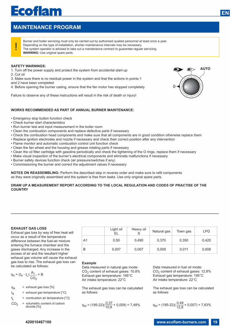
EXHAUST GAS LOSS
Exhaust gas loss by way of free heat will
occur as a result of the temperature
difference between the fuel-air mixture
entering the furnace chamber and the
gases discharged. Any increase in the
excess of air and the resultant higher
exhaust gas volume will cause the exhaust
gas loss to rise. The exhaust gas loss can
be calculated as follows:
qA = (tA - tL) A1 + BCO2
qA = exhaust gas loss [%]
tA = exhaust gas temperature [°C]
tL = combustion air temperature [°C]
CO2 = volumetric content of carbon dioxide [%]
Example
Data measured in natural gas mode:
CO2 content of exhaust gases: 10,8%
Exhaust gas temperature: 195°C
Air intake temperature: 22°C
The exhaust gas loss can be calculated
as follows:
qAf = (195-22)( 0,37
+ 0,009) = 7,48%10,8
Data measured in fuel oil mode:
CO2 content of exhaust gases: 12,8%
Exhaust gas temperature: 195°C
Air intake temperature: 22°C
The exhaust gas loss can be calculated
as follows:
qAf = (195-22)( 0,49
+ 0,007) = 7,83%12,8
Light oil
EL
Heavy oil
SNatural gas Town gas LPG
A1 0,50 0,490 0,370 0,350 0,420
B 0,007 0,007 0,009 0,011 0,008
0
AUTO
3
4
+
-1
2
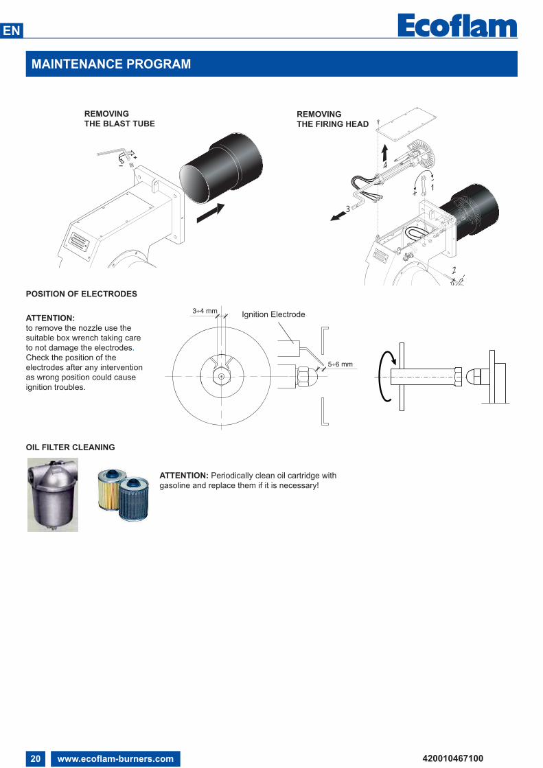
MAINTENANCE PROGRAM
ATTENTION:
to remove the nozzle use the
suitable box wrench taking care
to not damage the electrodes.
Check the position of the
electrodes after any intervention
as wrong position could cause
ignition troubles.
REMOVING
THE BLAST TUBEREMOVING
THE FIRING HEAD
POSITION OF ELECTRODES
420010467100
EN
www.ecoflam-burners.com20
5÷6 mm
3÷4 mmIgnition Electrode
OIL FILTER CLEANING
ATTENTION: Periodically clean oil cartridge with
gasoline and replace them if it is necessary!

TROUBLESHOOTING INSTRUCTIONS
TROUBLESHOOTING TABLE
OIL OPERATION
Bu
rne
r d
oe
sn
't sta
rt
Fu
el p
um
p n
ois
y /
un
prim
es / le
aks
Bu
rne
r sta
rts w
ith
co
ntin
uo
us p
re-
pu
rge
Bu
rne
r sta
rts a
nd
the
n g
oe
s in
to
lock-o
ut
Pilo
t Ig
nitio
n fa
ilure
(1
st sa
fety
tim
e -
L
FL o
nly
)
Ma
in Ig
nitio
n fa
ilure
(2
nd
sa
fety
tim
e)
Burn
er
lock-o
ut after
flam
e a
ppere
ance /
puls
atio
n
Fla
me c
ontrol r
epeats
the c
ycle
and d
oesn
’tgiv
e c
onse
nt
Sm
oke
in
fla
me
-d
ark
Ba
ch
ara
ch
Bu
rne
r d
oe
sn
'tsw
itch
in
to H
i fla
me
Bu
rne
r lo
ck-o
ut
du
rin
g o
pe
ratio
n
LFL LAL
STA
TU
S
CAUSES REMEDIES
MU
LTIC
ALO
R
MU
LT
IFL
AM
MA
IOR
OIL
FL
AM
HE
AV
Y
OIL
Preheating period too long Check GEFRAN controller, replace if necessary X X X YES YES
Defective Gefran controller Replace control unit X X X YES YES
PR
E-S
TA
RT
(MIS
SIN
G S
IGN
AL
S)
Defective control box unit Replace control box unit X X X X X X X X YES YES
No electrical power supplyWrong electrical connections
Check switches/contactorsCheck connections X YES YES
Air pressure switch not "closed" Check contacts X YES YES
Boiler thermostats open Check contacts X YES YES
Fan motor overload intervention Replace fuse X YES YES
Auxiliaries fuses interrupted Replace fuse X YES YES
Servomotor [CLOSE] position switch not reach Check servomotor settings X YES YES
PR
E-S
TA
RT
(OIL
PU
MP
) High vacuum in oil pipe due todirty filter
Clean filter or replace filtercartridge X X YES YES
Burner is higher than oil tank bymore than 3 m
Reduce Height or prepare a ringline pump X X YES YES
Air in the oil pipeline Re-tighten pipe connections X YES YES
SE
QU
EN
CE
STA
RT Servomotor [OPEN] position
switch not reach Check servomotor settings X YES YES
Servomotor [MIN] positionswitch not reach Check servomotor settings X YES YES
Extraneous Light Eliminate light source X YES YES
Fuel solenoid valve fails to close(Light oil Burner - direct ignition)
Clean valves or replace ifnecessary X YES YES
LA
CK
OF
AIR
Air pressure switch fail to connect to Terminal 14 Check contacts X YES NO
Fan contaminated/dirty Clean fan X X X YES NO
Fan motor rotation direction notcorrect Check direction and contactor X X X YES NO
IGN
ITIO
N &
FLA
ME
STA
BLIS
AT
ION
PE
RIO
D
Flame supervision circuitinternal test failed Replace control unit X YES NO
Pilot flame failure - Pilot gasvalves not open
Check valves contacts / replace ifnecessary X YES NO
Pilot flame establish - weakflame signal
Check flame sensorReplace if necessary X YES NO
Ignition transformer faulty Replace X X YES YES
Ignition cable & electrodesdefective Replace X X YES YES
Electrode bad position Check setting / replace ifnecessary X X YES YES
Fuel oil solenoid valve fails toopen
Check contacts and clean valves.Replace solenoid coil if necessary X YES YES
ON
LY
FO
R O
IL
BU
RN
ER
Air pressure switch not close,Oil pump contactor open Check air pressure switch contacts X NO YES
No oil supply Check shut-off valvesCheck Pump, replace if necessary X NO YES
Oil pump coupling broken Replace pump unit X NO YES
CO
MB
US
TIO
N
Flame sensor signal failure Clean, re-position or replace ifnecessary X X X X X YES YES
Head adjustment not correct Check settings X X X YES YES
Oil/Air mixture setting notcorrect Check settings X X X YES YES
Dirty combustion head Clean or replace disk if necessary X X X YES YES
Nozzle dirty or damaged Clean or replace nozzle ifnecessary X X YES YES
Fuel pressure inappropriate Adjust pressure or replace pump ifnecessary X X X YES YES
Capacity reduction Check filter, pump pressure andnozzle. Replace item if necessary X YES YES
Load control device does notclose
Check load control, replace ifnecessary X X YES YES
The list of faults/causes/possible solutions for a set of main failures is a guideline for professional personell authorised to carry out
service and maintenance.
Irregular burner operation or malfunction: check that every adjustment parameter is correctly set as per instruction on this manual.
420010467100
EN
www.ecoflam-burners.com 21

OPERATING TROUBLE
420010467100
EN
www.ecoflam-burners.com22
In case of operating trouble it should be
checked whether the system is in proper
working order.
Make a check for the following:
1. Availability of fuel.
Correct position of fuel selector switch.
2. Availability of electric power in the
burner system.
3. Proper functional order and setting of all
control and safety instruments such as
temperature controller, safety limiter, water
failure cut-out, electrical limit switches, etc.
If the trouble is not found to be due to any
of the above-mentioned points it will be
necessary to test the burner functions very
carefully.
Prevailing conditions:
The burner will be found to be out of
operation and in faulty and interlocked
position.
Proceed with searching for the cause of
the trouble and eliminate it. Unlock the
control box by pressing the fault eliminate
key and start the burner.
Do not press the fault eliminate key longer
than 10 seconds.
The start-up program will be initiated and
should be carefully monitored.
The possible cause of the fault may be
quickly found by reference to the fault
indicator of the control box and watching
the start-up and operating program.
Control program in the case of trouble
and fault indicator LAL 1... / LAL 2...
LAL 1... / LAL 2...
a-b Starting program
b-b’ In a number of time versions; idle
steps of the program unit to self-stop after
burner start-up (b’ = operating position of
program unit)
b(b’)-a After-flushing program after
regular stop. In the starting position “a” the
program unit will automatically stop or
initiate an immediate restart of the burner,
e.g. after a fault has been eliminated
• Duration of the safety period for single-
tube burners
•• Duration of the safety period for
burners with ignition gas valve
Basically, any type of trouble will result
in the immediate stop of the fuel supply.
At the same time, the program unit and
consequently the fault indicator will stop.
The type of trouble can be identified by the
symbol opposite to the reading mark of the
indicator:
◄ No start, e.g. because the “CLOSED”
signal from the “Air Damper CLOSED” limit
switch is missing or a contact is not closed
between terminals (12) and (4) or (4) and
(5); or the contacts of all control and safety
units in the controlled system are not
closed (e.g. gas pressure or air pressure
switches, temperature or pressure
switches, temperature or pressure
regulators).
▲ Operating stop because the “OPEN”
signal from the “Air Damper OPEN” limit
switch is missing.
Check and adjust the limit switch
concerned.
P Shut-off on trouble because there is
not air pressure signal at the beginning of
the air pressure check (apply only to LAL
2.25).
Any air pressure failure after this time
will also lead to a shut-off on trouble.
■ Shut-off on trouble because of a fault
in the flame monitoring circuit.
▼ Operating stop because the position
signal of the “Partial Load” limit switch (air
damper in “Partial Load” position) is not
available on terminal (8). Check and adjust
the limit switch concerned.
1 Shut-off on trouble because a flame
signal is not available on the expiry of the
(1st) safety time.
Any failure of the flame signal on the
expiry of the safety time will also lead
to a shut-off on trouble.
| Shut-off on trouble because the flame
signal failed during burner operation or a
lack of air has occurred.
◄ Shut-off on trouble during or after the
control program flow due to external light
(e.g. by flame not extinguished, leaking
fuel valves) or a faulty flame signal (e.g.
fault in flame monitoring circuit, or similar);
see flame monitor.
If the shut-off on trouble occurs at any
other time between start and pre-
ignition that is not identified by a
symbol as above, this will normally be
due to an early flame signal which is
considered to be a faulty flame signal.
The automatic furnace controller may
be unlocked immediately after a shut-off
on trouble using the unlock button with
integrated fault signal lamp or an external
switch. After it has been unlocked (and
after a defect with resultant operating stop
has been eliminated and after a voltage
failure), the program unit will in any case
return to its starting position with voltage
being only supplied to terminals 7, 9, 10
and 11 as preset by the control program. It
is only at this stage that the program of the
automatic furnace controller will restart the
burner.

APPENDIX
Control box - Damper actuators
DAMPER ACTUATORS SQM50...
Description
The SQM actuator is intended for use with two-stage sliding or modulating oil, gas or dual-fuel burners. The reversible actuator is fitted
with a synchronous motor which drives a shaft via a gearbox. The shaft end carries a coupling to drive the fuel and combustion air
controlling element.
The SQM actuator has been designed for dual-wire control by controller or switching units with change-over contacts.
Potentiometers can be installed for a range of applications on customer’s request.
The limit and auxiliary switches are set by means of manually adjustable latching cam plates. Scales are fitted between the disks to
facilitate the selection of the switching points.
The cam plates are provided with a small pointer for indicating the switching point of a scale between the setting ranges.
An additional scale fitted to the end of the cam roller serves to indicate the position of the actuator.
The drive unit may be disconnected from the controlling element by changing over a rocker arm mounted to the gearbox.
This will allow any desired position of the controller plate to be selected by hand. Drive and output will be coupled in the vertical
position of the rocker arm.
The fuel-air curve should be set over the full range of the cam plate so that operating safety will be retained also when the limit switch
is overrun.
420010467100
EN
www.ecoflam-burners.com 23
CONTROL BOX LAL...
R LRt5t11 t12
t13FS
min.LK0...
M 100%
RV
A
BV1
M2
Z
~M
P R
M1
T
t4
t3
t7 t1
TSA
B
t6
C D
7153a10/0498
BV: Fuel valve
FS: Flame signal amplifier
LK: Air damper
LR: Load controller
M: Fan or burner motor
R: Control thermostat or pressurestat
RV: Modulating fuel valve
Z: Ignition transformer
A: Starting type interval
A-B: Flame development interval
B: Burner has reached operating position
B-C: Burner operation (heat generation)
C-D: Regular shut-off
t1: Pre-ventilating time
t2: Safety time
t3: Pre-ignition time
t4: Fuel valve enable
t5: Load regulator enable
t11: “OPEN” run time of air damper
t12: “CLOSE” run time of air damper
APPENDIX
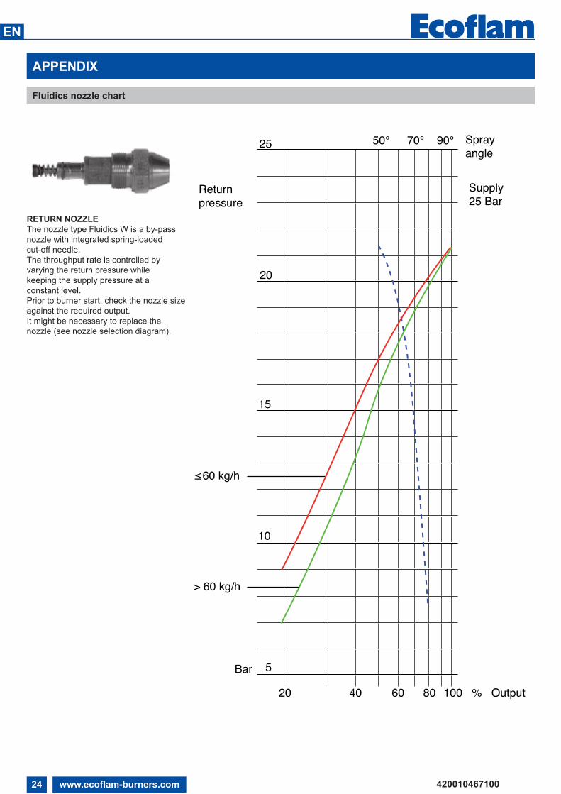
Fluidics nozzle chart
RETURN NOZZLE
The nozzle type Fluidics W is a by-pass
nozzle with integrated spring-loaded
cut-off needle.
The throughput rate is controlled by
varying the return pressure while
keeping the supply pressure at a
constant level.
Prior to burner start, check the nozzle size
against the required output.
It might be necessary to replace the
nozzle (see nozzle selection diagram).
25 50° 70° 90°
20
15
10
5Bar
Return pressure
20 40 60 80 100 % Output
Spray angle
Supply 25 Bar
≤60 kg/h
> 60 kg/h
420010467100
EN
www.ecoflam-burners.com24
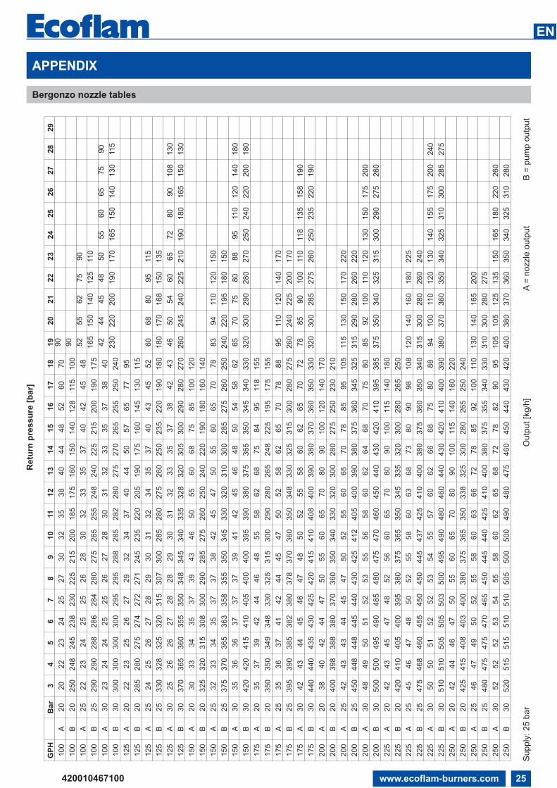
APPENDIX
Bergonzo nozzle tables
GP
HB
ar
34
56
78
910
11
12
13
14
15
16
17
18
19
20
21
22
23
24
25
26
27
28
29
100
A20
20
22
23
24
25
27
30
32
35
38
40
44
48
52
60
70
90
100
B20
250
248
245
238
230
225
215
200
185
175
160
150
140
128
115
100
90
100
A25
22
23
24
25
25
26
28
30
32
33
35
37
40
42
45
48
52
55
62
75
90
100
B25
290
290
288
286
284
280
275
265
255
248
240
225
215
200
190
175
165
150
140
125
110
100
A30
23
24
24
25
25
26
27
28
30
31
32
33
35
37
38
40
42
44
45
48
50
55
60
65
75
90
100
B30
300
300
300
300
295
295
288
285
282
280
275
270
265
255
250
240
230
220
200
190
170
165
150
140
130
115
125
A20
22
23
25
26
27
29
32
34
37
40
44
50
57
65
77
95
125
B20
285
280
275
274
272
271
245
235
220
205
190
175
160
145
130
115
125
A25
24
25
26
27
28
29
30
31
32
34
35
37
40
43
45
52
60
68
80
95
115
125
B25
330
328
325
320
315
307
300
285
280
275
260
250
235
220
190
180
180
170
168
150
135
125
A30
25
26
26
27
28
28
29
30
31
32
33
35
37
38
42
43
46
50
54
60
65
72
80
90
108
130
125
B30
370
365
360
355
350
348
345
340
335
328
320
305
300
290
280
270
260
245
240
225
210
190
180
165
150
130
150
A20
30
33
34
35
37
39
43
46
50
55
60
68
75
85
100
120
150
B20
325
320
315
308
300
290
285
275
260
250
240
220
190
180
160
140
150
A25
32
33
34
35
37
37
38
42
45
47
50
55
60
65
70
78
83
94
110
120
150
150
B25
375
370
365
363
358
355
350
345
330
320
310
300
285
275
260
250
240
220
195
180
150
150
A30
35
36
36
37
37
37
39
41
42
45
46
48
50
54
58
62
65
70
75
80
88
95
110
120
140
180
150
B30
420
420
415
410
405
400
400
395
390
380
375
365
350
345
340
330
320
300
290
280
270
250
240
220
200
180
175
A20
35
37
39
42
44
46
48
55
58
62
68
75
84
95
118
155
175
B20
350
350
349
348
330
325
315
300
290
280
265
248
225
195
175
155
175
A25
35
36
37
41
42
44
45
47
50
52
58
62
65
70
78
88
95
110
120
140
170
175
B25
395
390
385
382
380
378
370
360
350
348
330
325
315
300
280
275
260
240
225
200
170
175
A30
42
43
44
45
46
47
48
50
52
55
58
60
62
65
70
72
78
85
90
100
110
118
135
158
190
175
B30
440
440
435
430
425
420
415
410
408
400
390
380
370
360
350
330
320
300
285
275
260
250
235
220
190
200
A20
38
40
42
44
47
50
55
60
65
70
80
90
100
120
140
170
200
B20
400
398
388
380
370
360
350
340
330
320
300
280
275
250
230
210
200
A25
42
43
43
44
45
47
50
52
55
60
65
70
78
85
95
105
115
130
150
170
220
200
B25
450
448
448
445
440
430
425
412
405
400
390
380
375
360
345
325
315
290
280
260
220
200
A30
48
49
50
51
52
53
55
56
58
60
62
64
68
70
75
80
85
92
100
110
120
130
150
175
200
200
B30
500
500
495
490
485
480
475
470
460
450
440
430
420
410
395
385
375
350
340
325
315
300
290
275
260
225
A20
42
43
45
47
48
52
56
60
65
70
80
90
100
115
140
180
225
B20
420
410
405
400
395
380
375
365
350
345
335
320
300
280
265
250
225
A25
45
46
47
48
50
52
55
58
60
63
68
73
80
90
98
108
120
140
160
180
225
225
B25
475
468
460
455
450
450
445
437
425
410
400
380
375
360
350
340
315
300
280
260
240
225
A30
50
50
51
52
52
53
54
55
57
60
62
66
68
75
80
88
94
100
110
120
130
140
155
175
200
240
225
B30
510
510
505
505
503
500
495
490
480
460
440
430
420
410
400
390
380
370
360
350
340
325
310
300
285
275
250
A20
42
44
46
47
50
55
60
65
70
80
90
100
115
140
160
220
250
B20
425
415
408
403
400
380
375
365
350
338
325
300
280
265
250
240
250
A25
46
47
49
50
52
55
58
60
63
66
72
78
85
92
100
110
130
140
165
200
250
B25
480
475
475
470
465
450
445
440
425
410
400
380
375
355
340
330
310
300
280
275
250
A30
52
52
52
53
54
55
58
60
62
65
68
72
78
82
90
95
105
105
125
135
150
165
180
220
260
250
B30
520
515
515
510
510
505
500
500
490
480
475
460
450
440
430
420
400
380
370
360
350
340
325
310
280
Retu
rn p
ressu
re [
bar]
Supply
: 25 b
ar
Outp
ut
[kg/h
]A
= n
ozzle
ou
tpu
tB
= p
um
p o
utp
ut
420010467100
EN
www.ecoflam-burners.com 25
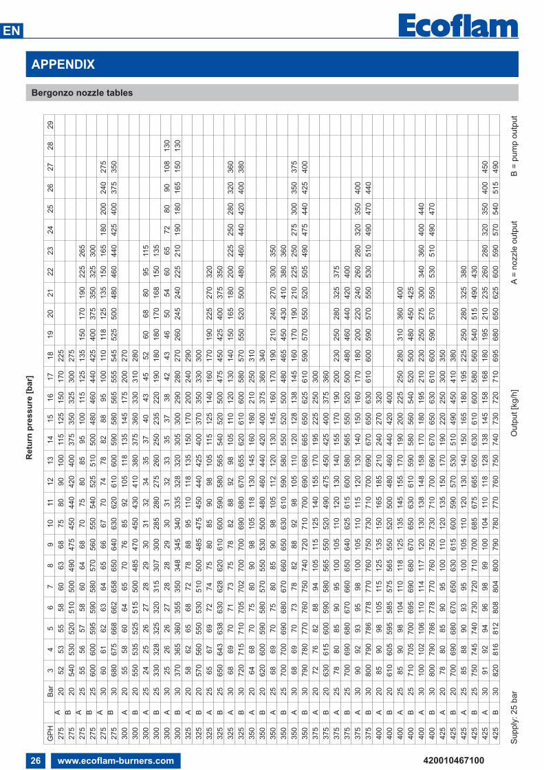
APPENDIX
Bergonzo nozzle tables
Retu
rn p
ressu
re [
bar]
Supply
: 25 b
ar
Outp
ut
[kg/h
]A
= n
ozzle
ou
tpu
tB
= p
um
p o
utp
ut
GP
HB
ar
34
56
78
910
11
12
13
14
15
16
17
18
19
20
21
22
23
24
25
26
27
28
29
275
A20
52
53
55
58
60
63
68
75
80
90
100
115
125
150
170
225
275
B20
540
530
520
510
500
490
475
450
440
420
400
375
350
325
300
275
275
A25
55
56
57
58
60
64
68
70
75
80
85
95
100
115
125
135
150
170
190
225
265
275
B25
600
600
595
590
580
570
560
550
540
525
510
500
480
460
440
425
400
375
350
325
300
275
A30
60
61
62
63
64
65
66
67
70
74
78
82
88
95
100
110
118
125
135
150
165
180
200
240
275
275
B30
680
675
668
662
658
650
640
630
620
610
600
590
580
565
555
545
525
500
480
460
440
425
400
375
350
300
A20
55
58
60
64
65
70
76
85
92
105
118
135
145
175
200
270
300
B20
550
535
525
515
500
485
470
450
430
410
380
375
360
330
310
280
300
A25
24
25
26
27
28
29
30
31
32
34
35
37
40
43
45
52
60
68
80
95
115
300
B25
330
328
325
320
315
307
300
285
280
275
260
250
235
220
190
180
180
170
168
150
135
300
A30
25
26
26
27
28
28
29
30
31
32
33
35
37
38
42
43
46
50
54
60
65
72
80
90
108
130
300
B30
370
365
360
355
350
348
345
340
335
328
320
305
300
290
280
270
260
245
240
225
210
190
180
165
150
130
325
A20
58
62
65
68
72
78
88
95
110
118
135
150
170
200
240
290
325
B20
570
560
550
530
510
500
485
475
450
440
425
400
370
350
330
300
325
A25
65
67
69
72
74
75
80
85
90
98
105
115
125
140
160
170
190
225
270
320
325
B25
650
643
638
630
628
620
610
600
590
580
565
540
520
500
475
450
425
400
375
350
325
A30
68
69
70
71
73
75
78
82
88
92
98
105
110
120
130
140
150
165
180
200
225
250
280
320
360
325
B30
720
715
710
705
702
700
700
690
680
670
655
620
610
600
580
570
550
520
500
480
460
440
420
400
380
350
A20
64
68
70
75
80
90
98
105
118
130
145
160
180
210
250
310
350
B20
620
600
590
580
570
550
530
500
480
460
440
420
400
375
360
340
350
A25
68
69
70
75
80
85
90
98
105
112
120
130
145
160
170
190
210
240
270
300
350
350
B25
700
700
690
680
670
660
650
630
610
590
580
550
520
500
480
465
450
430
410
380
360
350
A30
68
69
70
73
78
82
88
92
98
105
110
120
128
138
145
160
170
190
210
225
250
275
300
350
375
350
B30
790
780
770
760
750
740
720
710
700
690
680
665
650
625
610
590
570
550
520
505
490
475
440
425
400
375
A20
72
76
82
88
94
105
115
125
140
155
170
195
225
250
300
375
B20
630
615
600
590
580
565
550
520
490
475
450
425
400
375
360
375
A25
78
80
85
90
95
100
105
110
120
130
140
155
170
190
200
230
250
280
325
375
375
B25
700
690
680
670
660
650
640
625
615
600
580
565
550
520
500
480
460
440
420
400
375
A30
90
92
93
95
98
100
105
110
115
120
130
140
150
160
170
180
200
220
240
260
280
320
350
400
375
B30
800
790
786
778
770
760
750
730
710
700
690
670
650
630
610
600
590
570
550
530
510
490
470
440
400
A20
85
90
98
105
115
125
135
150
165
185
210
240
270
320
400
B20
610
605
595
585
575
565
550
520
500
480
460
440
420
400
400
A25
85
90
98
104
110
118
125
135
145
155
170
190
200
225
250
280
310
360
400
400
B25
710
705
700
695
690
680
670
650
630
610
590
580
560
540
520
500
480
450
425
400
A30
100
102
106
110
114
117
120
130
138
148
158
170
180
195
210
230
250
275
300
340
360
400
440
400
B30
800
790
786
778
770
760
750
730
710
700
690
670
650
630
610
600
590
570
550
530
510
490
470
425
A20
78
80
85
90
95
100
110
120
135
150
170
190
220
250
300
350
425
B20
700
690
680
670
650
630
615
600
590
570
530
510
490
450
410
380
425
A25
85
88
90
93
95
100
105
110
120
130
140
150
165
180
195
225
250
280
325
380
425
B25
750
745
740
730
720
710
700
685
675
665
650
630
610
600
580
560
540
515
490
430
425
A30
91
92
94
96
98
99
100
104
110
118
128
138
145
158
168
180
195
210
235
260
280
320
350
400
450
425
B30
820
816
812
808
804
800
790
780
770
760
750
740
730
720
710
695
680
650
625
600
590
570
540
515
490
420010467100
EN
www.ecoflam-burners.com26

27www.ecoflam-burners.com
EN
420010467100
APPENDIX
Bergonzo nozzle tables
Retu
rn p
ressu
re [
bar]
Supply
: 25 b
ar
Outp
ut
[kg/h
]A
= n
ozzle
ou
tpu
tB
= p
um
p o
utp
ut
GP
HB
ar
34
56
78
910
11
12
13
14
15
16
17
18
19
20
21
22
23
24
25
26
27
28
29
450
A20
86
90
94
98
105
115
125
135
150
170
195
225
250
280
340
380
450
B20
700
685
660
645
635
620
605
585
570
545
530
515
490
470
440
410
450
A25
92
95
100
105
110
115
120
130
140
150
165
175
190
210
230
260
280
325
375
425
450
B25
805
800
790
775
760
745
730
715
700
690
670
650
625
605
580
560
540
520
500
480
450
A30
100
102
105
108
111
114
117
120
130
140
150
160
170
180
190
220
240
260
280
310
350
380
425
475
450
B30
860
856
850
842
834
826
818
810
790
760
750
740
730
720
700
680
660
640
620
600
580
540
520
500
475
A20
82
88
95
100
110
120
130
145
160
170
195
225
260
300
360
475
B20
800
780
760
740
720
700
680
655
625
600
580
560
520
480
440
475
A25
98
102
108
112
116
120
130
140
150
160
170
180
195
225
250
275
300
350
400
475
475
B25
910
905
900
880
860
840
820
800
780
750
730
710
690
670
650
620
590
560
530
500
475
A30
104
107
110
113
117
120
125
135
145
155
163
170
180
190
200
225
250
275
300
325
360
390
440
480
475
B30
1000
990
975
965
945
930
915
900
890
880
860
840
820
800
780
760
730
700
680
660
640
620
590
460
500
A20
94
102
106
113
120
130
150
170
190
210
230
250
280
325
380
500
B20
800
780
760
740
720
710
680
660
640
610
580
560
520
500
475
500
A25
100
104
108
116
120
130
140
150
160
170
190
210
230
250
270
325
350
400
475
500
B25
900
895
880
865
850
845
830
815
800
780
750
720
700
670
650
620
600
580
550
500
A30
110
113
117
120
125
130
135
140
150
160
170
180
190
220
250
280
250
300
325
350
380
425
480
520
500
B30
1000
990
980
970
960
950
940
925
910
900
880
860
840
820
800
775
750
725
700
775
750
725
600
575
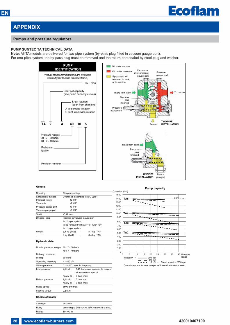
28 www.ecoflam-burners.com
EN
420010467100
APPENDIX
Pumps and pressure regulators
PUMP SUNTEC TA TECHNICAL DATA
Note: All TA models are delivered for two-pipe system (by-pass plug fitted in vacuum gauge port).
For one-pipe system, the by-pass plug must be removed and the return port sealed by steel plug and washer.
TA : type
TA 2 A 40 10 5
PUMPIDENTIFICATION
(Not all model combinations are availableConsult your Suntec representative)
Gear set capacity(see pump capacity curves)
Shaft rotation(seen from shaft end)
A : clockwise rotationC : anti clockwise rotation
Pressure range :30 : 7 - 30 bars40 : 7 - 40 bars
Preheater facility
Revision number
Oil under suction
Oil under pressure Pressuregauge port
To nozzle
Pressureadjustment
By-passplug
inserted
By-passplug
removed
Return
Intake from Tank
TWO PIPEINSTALLATION
Vacuum orinlet pressure
gauge portBy-passed oilreturned to tank,or to suction
Intake from Tank
ONE PIPEINSTALLATION
Returnplugged
Inlet end return G 1/2"To nozzle G 1/2"Pressure gauge port G 1/4"Vacuum gauge port G 1/4"
4020 30 3510 15 255
1000
1200
1400
200
400
0
600
800
TA5
TA4
TA3
TA2
0
900
1500
1100
1300
100
300
500
700
General
Mounting Flange mountingConnection threads Cylindrical according to ISO 228/1
Shaft Ø 12 mmBy-pass plug Inserted in vacuum gauge port
for 2 pipe system;to be removed with a 3/16" Allen keyfor 1 pipe system
Weight 5,4 kg (TA2) - 5,7 kg (TA3)6 kg (TA4) - 6,4 kg (TA5)
Hydraulic data
Nozzle pressure ranges 30 : 7 - 30 bars40 : 7 - 40 bars
Delivery pressuresetting 30 barsOperating viscosity 4 - 450 cStOil temperature 0 - 140°C max. in the pumpInlet pressure light oil : 0,45 bars max. vacuum to prevent
air separation from oilheavy oil : 5 bars max.
Return pressure light oil : 5 bars max.heavy oil : 5 bars max.
Rated speed 3600 rpm max.Starting torque 0,3 N.m
Choice of heater
Cartridge Ø 12 mmFitting according to DIN 40430, NFC 68190 (N°9 elec.)Rating 80-100 W
Data shown are for new pumps, with no allowance for wear.
Pump capacityCapacity (L/h)
Viscosity = 200 cSt20 cSt
5 cSt - Rated speed = 2850 rpm
Pressure(bars)
2850 rpm

29www.ecoflam-burners.com
EN
420010467100
APPENDIX
Electrical diagrams
TOT.
SHEE
T
SHEE
TDE
SIGNE
RDE
SCRIP
TION
DATE
FIST
CREA
TION
CODE
SIGNA
TURE
R&D
DEPA
RTM
ENT
CONT
ROLL
EREc
oflam
Bru
ciat
ori
SERV
OMOT
OR
FLAM
E SEN
SOR
S.p.
AEC
N FIR
ST CR
EATIO
N
BY TERM LAWS WE RESERVED THE PROPERTY OF THIS WIRING DIAGRAM WITH PROHIBITION OF USE AND REPRODUCTION
LEAK
AGE C
ONTR
OL
CONT
ROL B
OX
DATE
ECN
MOD
ICAT
ION
MOD
IFICA
TION
DESC
RIPTIO
NEC
N M
ODIFI
CATIO
N
MAIO
R P 30
0.1-4
00.1-
500.1
-600
.1 PR
A.PO
ZZOB
ON
21-0
5-20
10
2
4201
1003
0501
1 A
.RIGO
NI
LAND
IS SQ
M 50
.481A
2
B
RBA1
0PC0
89LA
NDIS
LAL 1
.25
18-1
1-20
10RB
A10P
M22
5
F
1
ED
23
4
CBA
12
34
56
78
FED
56
7
CB
8
A
98
745
6
21
3
1110
121012
11
13
2
45
6 98
7
FMV
97 98
FMV95 96
PT
STC PT
STS
TP
STAB
HLF
400V
230V
FMV
3M
MV
UV
W
KMV
RS
TNO
LINE
LOAD
Z
FU SAL
HLBT
TV
SAM
A
12
30
KA
HLB
HLF
BYV
gYV
gS
SAM
A
12
30
pos 0
: FER
MO
/ STO
P
pos 2
: BAS
SA FI
AMM
A/LO
W FL
AME/
1re A
LLUR
E/BA
JA LL
AMA
pos 3
: AUT
OMAT
ICO/
AUTO
MAT
IC/A
UTOM
ATIQ
UE/A
UTOM
ATIC
O
pos 1
: ALT
A FIA
MM
A/HI
GH FL
AME/
2meA
LLUR
E/AL
TA LL
AMA
COM
MUT
ATOR
E MAN
UALE
-AUT
OMAT
ICO
CONM
UTAD
OR M
ANUA
L-AUT
OMAT
ICO
INTE
RRRU
PTEU
R MAN
UEL-A
UTOM
ATIQ
UESW
ITCH
MAN
UAL-A
UTOM
ATIC
9
Q
NR
ST
76
58
S NTRPE
50 H
z 400
V
1312
1110
12
43
512
LAND
IS LA
L 1.25
76
810
911
1514
1317
1618
3122
2019
2123
2432
LAND
IS SQM
50.48
1A2
N1M
2111
112
23
1322
2314
2715
244
525
266
1617
7
41
23

30 www.ecoflam-burners.com
EN
420010467100
APPENDIX
Electrical diagrams
TOT.
SHEE
T
SHEE
TDE
SIGNE
RDE
SCRIP
TION
DATE
FIST
CREA
TION
CODE
SIGNA
TURE
R&D
DEPA
RTM
ENT
CONT
ROLL
EREc
oflam
Bru
ciat
ori
SERV
OMOT
OR
FLAM
E SEN
SOR
S.p.
AEC
N FIR
ST CR
EATIO
N
BY TERM LAWS WE RESERVED THE PROPERTY OF THIS WIRING DIAGRAM WITH PROHIBITION OF USE AND REPRODUCTION
LEAK
AGE C
ONTR
OL
CONT
ROL B
OX
DATE
ECN
MOD
ICAT
ION
MOD
IFICA
TION
DESC
RIPTIO
NEC
N M
ODIFI
CATIO
N
MAIO
R P 30
0.1-4
00.1-
500.1
-600
.1 PR
A.PO
ZZOB
ON
21-0
5-20
10
2
4201
1003
0501
2 A
.RIGO
NI
LAND
IS SQ
M 50
.481A
2
B
RBA1
0PC0
89LA
NDIS
LAL 1
.25
18-1
1-20
10RB
A10P
M22
5
F
1
ED
23
4
CBA
12
34
56
78
FED
56
7
CB
8
A
KA
STAB
YVg
YVgS
HLF
Q Z FU MV
TV B FMV
HLB
KMV
SAL
STC
STS
HLBT
SAMA
INTE
RRUT
TORE
GEN
ERAL
E CON
FUSIB
ILEMA
IN SW
ITCH
WITH
FUSE
INTE
RRUP
TEUR
GEN
ERAL
AVEC
FUSIB
LEIN
TERR
UPTO
R GEN
ERAL
CON
FUSIB
LE
FILTR
O AN
TIDIST
URBO
ANTJ
AMM
ING
FILTE
RFIL
TRE A
NTIPA
RASIT
ESFIL
TRO
DE PR
OTEC
ION
ANT
IDIST
URBIO
FUSIB
ILEFU
SEFU
SIBLE
FUSIB
LE
MOT
ORE V
ENTIL
ATOR
EM
OTOR
FAN
MUT
EUR V
ENTIL
ATEU
RM
OTOR
VENT
ILADO
R
TRAS
FORM
ATOR
EIG
NITIO
N TR
ANSF
ORM
ERTR
ANSF
ORMA
TEUR
D'AL
LUMA
GETR
ANSF
ORMA
DOR
FOTO
CELL
ULA
UV CE
LLCE
LLUL
E UV
FOTO
CELU
LA
RELE
' TER
MICO
MOT
ORE V
ENTIL
ATOR
EM
OTOR
THER
MAL R
ELAY
(FAN
MOT
OR)
RELA
IS TH
ERM
IQUE
MOT
EUR V
ENTIL
ATEU
RRE
LE' T
ERM
ICO M
OTOR
VENT
ILADO
R
LAM
PADA
DI B
LOCC
OLO
CK-O
UT LA
MP
LAM
PE D
E SEC
URITE
ESPIA
DE B
LOQU
EO
CONT
ATTO
RE M
OTOR
E VEN
TILAT
ORE
REM
OTE C
ONTR
OL SW
ITCH
(FAN
MOT
OR)
CONT
ACTE
UR M
OTEU
R VEN
TILAT
EUR
TELE
RRUP
TOR M
OTOR
VENT
ILATO
R
INTE
RRUT
TORE
DI L
INEA
WOR
KING
SWITC
HIN
TERR
UPTE
UR D
E LIG
NEIN
TERR
UPTO
R DE L
INEA
TERM
OSTA
TO CA
LDAI
ABO
ILER T
HERM
OSTA
TTH
ERM
OSTA
T CHA
UDIER
ETE
RMOS
TATO
CALD
ERA
TERM
OSTA
TO D
I SIC
UREZ
ZASA
FETY
THER
MOS
TAT
THER
MOS
TAT D
E SEC
URITE
TERM
OSTA
TO D
E SEG
URID
AD
LAM
PADA
DI B
LOCC
O TE
RMICO
THER
MAL L
OCK-
OUT L
AMP
LAM
PE D
E THE
RMAL
DE S
ECUR
ITEES
PIA D
E BLO
QUEO
RELE
TERM
ICO
COM
MUT
ATOR
E MAN
UALE
-AUT
OMAT
ICOSW
ITCH
(MAN
UAL-A
UTOM
ATIC
))IN
TERR
UPTE
UR M
ANUE
L-AUT
OMAT
IQUE
CONM
UTAD
OR M
ANUA
L-AUT
OMAT
ICO
TERM
OSTA
TO D
I ALT
A-BA
SSA
FIAM
MAHI
GH-LO
W FL
AME T
HERM
OSTA
TTH
ERM
OSTA
T GRA
NDE-P
ETIRE
ALL
URE
TERM
OSTA
TO D
E ALT
A-BA
JA LL
AMA
ELET
TROV
ALVO
LA G
ASOL
IOOI
L SOL
ENOI
D VA
LVE
ELCT
ROVA
NNE M
AZOU
TEL
ECTR
OVAL
VULA
DE G
ASOL
EO
ELET
TROV
ALVO
LA G
ASOL
IO D
I SIC
UREZ
ZAEX
TRA
SAFE
TY O
IL SO
LENO
ID VA
LVE
ELEC
TROV
ANNE
MAZ
OUT D
E SEC
URITE
ELEC
TROV
ALVU
LA D
E GAS
OLEO
DE S
EGUR
IDAD
LAM
PADA
DI F
UNZIO
NAM
ENTO
WOR
KING
LAM
PLA
MPE
DE F
ONCT
IONN
EMEN
TES
PIA D
E FUN
CION
AMIEN
TO
RELE
'RE
LAY
RELA
ISRE
LE'
(15°)
III:(30
°) IV:
(70°)
I:(0°
) II:
(0°) V
II:(0°
) VIII:
(0°) V
I:(0°
) V:
CAM
MA N
ON U
TILIZZ
ATA
CAM
MA N
ON U
TILIZZ
ATA
CAM
MA D
I CHI
USUR
A TOT
ALE
CAM
MA D
I REG
OLAZ
IONE
ARIA
DI A
CCEN
SIONE
CAM
MA D
I REG
OLAZ
IONE
ARIA
DI B
ASSA
CAM
MA D
I REG
OLAZ
IONE
ARIA
DI M
ASSIM
A
CAM
MA N
ON U
TILIZZ
ATA
CAM
MA N
ON U
TILIZZ
ATA
717
166
2625
54
2415
2714
2322
133
212
111
21
M1 N
LAND
IS SQM
50.48
1A2
REGO
LAZIO
NE CA
MM
E MAI
OR P
300/
600.1
PR

31www.ecoflam-burners.com
EN
420010467100
APPENDIX
Spare parts
MA
IOR
P 5
00.1
PR
MA
IOR
P 6
00.1
PR
4140 46423
56
89
3043
4445
39
FIN
DE
R
4
2
18
FIND
ER
1516
1211
17
27
26
0
AU
TO
0I
22 25 24 23
14
10
13
21
7
38
19
3732
20
35
33
36
34
2829
47
31
49
48
1
3
2
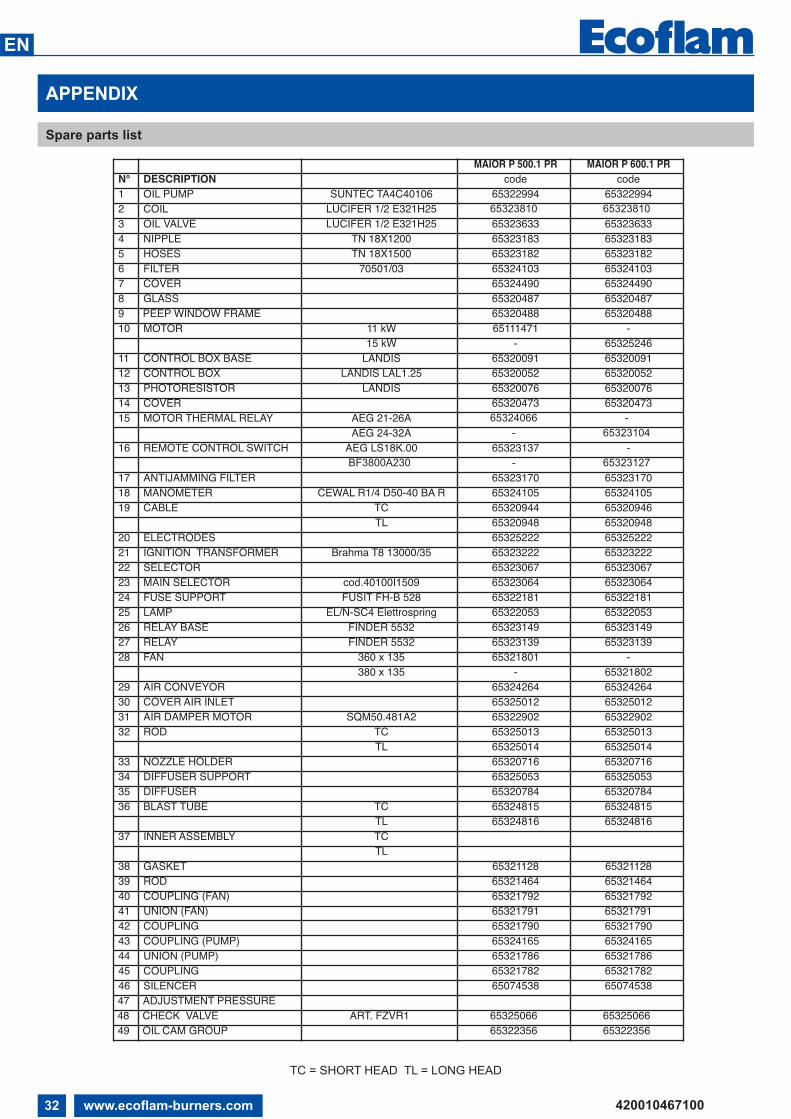
32 www.ecoflam-burners.com
EN
420010467100
APPENDIX
Spare parts list
TC = SHORT HEAD TL = LONG HEAD
MAIOR P 500.1 PR MAIOR P 600.1 PRN° DESCRIPTION code code1 OIL PUMP SUNTEC TA4C40106 65322994 653229942 COIL LUCIFER 1/2 E321H25 65323810 65323810
3 OIL VALVE LUCIFER 1/2 E321H25 65323633 653236334 NIPPLE TN 18X1200 65323183 653231835 HOSES TN 18X1500 65323182 653231826 FILTER 70501/03 65324103 653241037 COVER 65324490 653244908 GLASS 65320487 653204879 PEEP WINDOW FRAME 65320488 6532048810 MOTOR 11 kW 65111471 -
15 kW - 6532524611 CONTROL BOX BASE LANDIS 65320091 6532009112 CONTROL BOX LANDIS LAL1.25 65320052 6532005213 PHOTORESISTOR LANDIS 65320076 6532007614 COVER 65320473 6532047315 MOTOR THERMAL RELAY AEG 21-26A 65324066 -
AEG 24-32A - 65323104
16 REMOTE CONTROL SWITCH AEG LS18K.00 65323137 -BF3800A230 - 65323127
17 ANTIJAMMING FILTER 65323170 6532317018 MANOMETER CEWAL R1/4 D50-40 BA R 65324105 6532410519 CABLE TC 65320944 65320946
TL 65320948 6532094820 ELECTRODES 65325222 6532522221 IGNITION TRANSFORMER Brahma T8 13000/35 65323222 6532322222 SELECTOR 65323067 6532306723 MAIN SELECTOR cod.40100I1509 65323064 6532306424 FUSE SUPPORT FUSIT FH-B 528 65322181 6532218125 LAMP EL/N-SC4 Elettrospring 65322053 6532205326 RELAY BASE FINDER 5532 65323149 6532314927 RELAY FINDER 5532 65323139 6532313928 FAN 360 x 135 65321801 -
380 x 135 - 6532180229 AIR CONVEYOR 65324264 6532426430 COVER AIR INLET 65325012 6532501231 AIR DAMPER MOTOR SQM50.481A2 65322902 6532290232 ROD TC 65325013 65325013
TL 65325014 6532501433 NOZZLE HOLDER 65320716 6532071634 DIFFUSER SUPPORT 65325053 6532505335 DIFFUSER 65320784 6532078436 BLAST TUBE TC 65324815 65324815
TL 65324816 6532481637 INNER ASSEMBLY TC
TL38 GASKET 65321128 6532112839 ROD 65321464 6532146440 COUPLING (FAN) 65321792 6532179241 UNION (FAN) 65321791 65321791 42 COUPLING 65321790 65321790 43 COUPLING (PUMP) 65324165 6532416544 UNION (PUMP) 65321786 6532178645 COUPLING 65321782 6532178246 SILENCER 65074538 6507453847 ADJUSTMENT PRESSURE48 CHECK VALVE ART. FZVR1 65325066 6532506649 OIL CAM GROUP 65322356 65322356

33www.ecoflam-burners.com
EN
420010467100

34 www.ecoflam-burners.com
EN
420010467100

35www.ecoflam-burners.com
EN
420010467100

Ecoflam Bruciatori S.p.A.
Via Roma, 64 - 31023 Resana (TV) - Italy
Tel. +39 0423 719500
Fax +39 0423 719580
http://www.ecoflam-burners.com
e-mail: [email protected]à soggetta alla direzione e al coordinamento di Ariston Thermo S.p.A.
Via A. Merloni, 45 - 60044 Fabriano (AN) - CF 01026940427
Ecoflam Bruciatori S.p.A. reserves the right to make any adjustments, without prior notice, which is considered necessary
or useful to its products, without affecting their main features
Ecoflam Bruciatori S.p.A. si riserva il diritto di apportare ai prodotti le modifiche che riterrà necessarie o utili, senza
pregiudicarne le caratteristiche principali.
La maison Ecoflam Bruciatori S.p.A. se réserve le droit d’apporter les modifications qu’elle jugera nécessaires ou utiles
à ses produits sans pour autant nuire à leurs caractéristiques principales
Ecoflam Bruciatori S.p.A. se reserva el derecho a introducir en sus productos todas las modificaciones que considere
necesarias o utiles, sin prejudicar sus caracteristicas
“Ecoflam Bruciatori S.p.A.” оставляет за собой право вносить в конструкцию оборудования любые необходимые
изменения без особого предупреждения