light load high efficiency, 31v, buck regulator nr110e … · light load high efficiency, 31v, buck...
TRANSCRIPT
Light Load High Efficiency, 31V, Buck Regulator
NR110E series
SANKEN ELECTRIC CO., LTD.
Jun. 21, 2016
Rev.1.4 1
http://www.sanken-ele.co.jp
General Descriptions The NR110E series is buck regulator ICs integrates
High-side power MOSFET. The feature increasing
efficiency at light loads allows the device to be used in
the energy-saving applications. With the current mode
control, ultra low ESR capacitors such as ceramic
capacitors can be used. The ICs have protection functions
such as Over-Current Protection (OCP), Under-Voltage
Lockout (UVLO) and Thermal Shutdown (TSD). An
adjustable Soft-Start by an external capacitor prevents the
excessive inrush current at turn-on. The ICs integrate
phase compensation circuit which reduces the number of
external components and simplifies the design of
customer application. The ON/OFF pin (EN Pin) turns
the regulator on or off and helps to achieve low power
consumption requirements. The NR110E series is
available in an 8-pin SOIC package with an exposed
thermal pad on the back side.
Features & Benefits Current mode PWM control
Up to 94% Efficiency,
Up to 68% Efficiency at IO = 20mA Light Load
Adjustable “Over Current Protection(OCP)”
Current mode PWM control
Stable with low ESR ceramic output capacitors
Built-in protection function
Over Current Protection (OCP)
Thermal Shutdown (TSD)
Under Voltage Lockout (UVLO)
Built-in phase compensation
Adjustable Soft-Start with an external capacitor
Turn ON/OF the regulator function
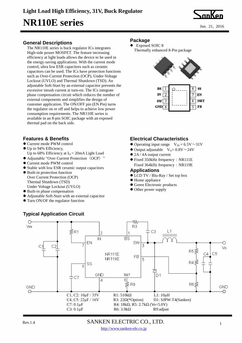
Package
Exposed SOIC 8
Thermally enhanced 8-Pin package
Electrical Characteristics Operating input range VIN = 6.5V~31V
Output adjustable VO= 0.8V~24V
2A / 4A output current
Fixed 350kHz frequency:NR111E
Fixed 364kHz frequency:NR119E
Applications LCD TV / Blu-Ray / Set top box
Home appliance
Green Electronic products
Other power supply
Typical Application Circuit
Arial 10pt
発行日
C1, C2: 10μF / 35V R1: 510kΩ L1: 10μH
C4, C5: 22μF / 16V R3: 22Ω(*Option) D1: SJPW-T4(Sanken)
C7: 0.1μF R4: 18kΩ, R5: 2.7kΩ (Vo=5.0V)
C3: 0.1μF R6: 3.9kΩ R9:adjust
Light Load High Efficiency, 31V, Buck Regulator
NR110E series
SANKEN ELECTRIC CO., LTD.
Jun. 21, 2016
Rev.1.4 2
http://www.sanken-ele.co.jp
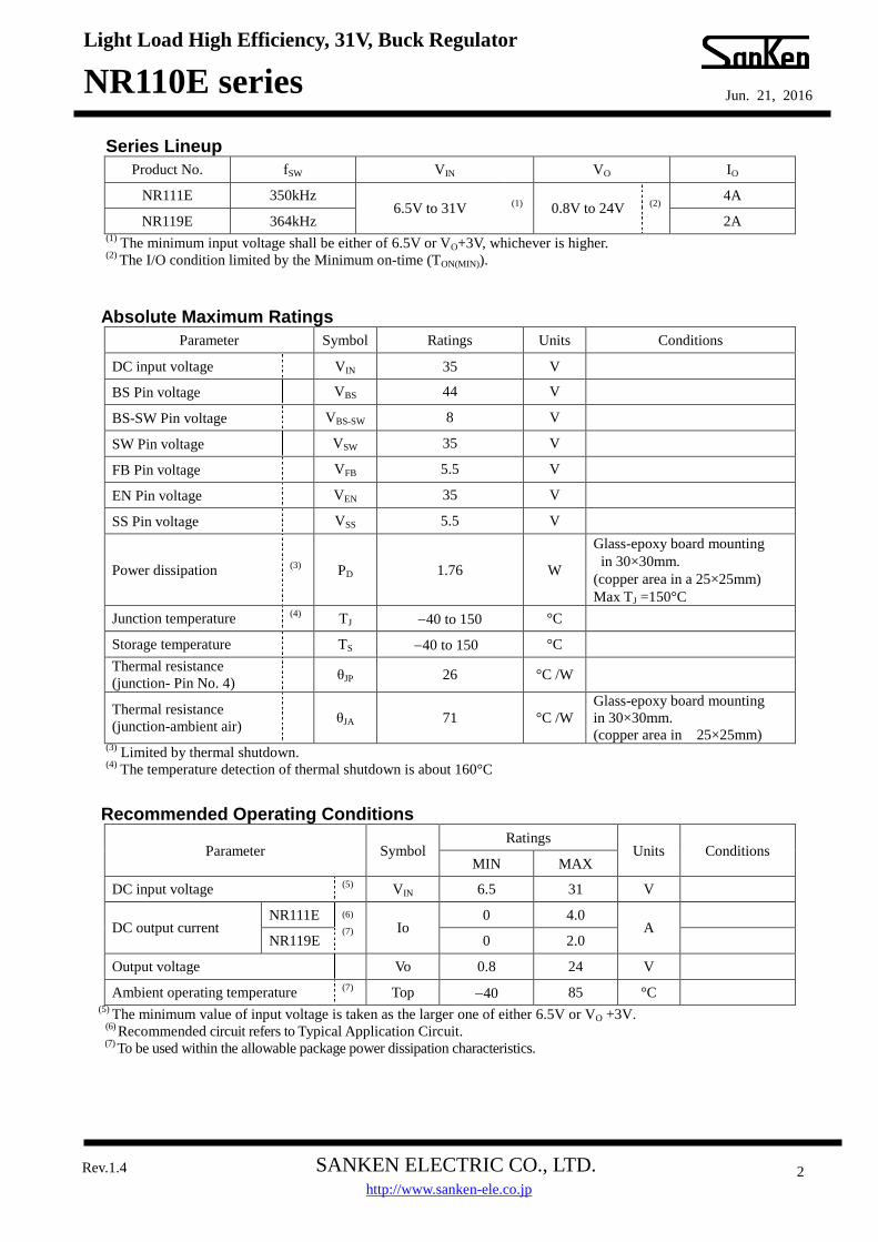
Series Lineup
Product No. fSW VIN VO IO
NR111E 350kHz 6.5V to 31V
(1) 0.8V to 24V
(2) 4A
NR119E 364kHz 2A (1)
The minimum input voltage shall be either of 6.5V or VO+3V, whichever is higher. (2)
The I/O condition limited by the Minimum on-time (TON(MIN)).
Absolute Maximum Ratings
Parameter Symbol Ratings Units Conditions
DC input voltage VIN 35 V
BS Pin voltage VBS 44 V
BS-SW Pin voltage VBS-SW 8 V
SW Pin voltage VSW 35 V
FB Pin voltage VFB 5.5 V
EN Pin voltage VEN 35 V
SS Pin voltage VSS 5.5 V
Power dissipation (3)
PD 1.76 W
Glass-epoxy board mounting
in 30×30mm.
(copper area in a 25×25mm)
Max TJ =150°C
Junction temperature (4)
TJ 40 to 150 °C
Storage temperature TS 40 to 150 °C
Thermal resistance
(junction- Pin No. 4) θJP 26 °C /W
Thermal resistance
(junction-ambient air) θJA 71 °C /W
Glass-epoxy board mounting
in 30×30mm.
(copper area in 25×25mm) (3)
Limited by thermal shutdown. (4)
The temperature detection of thermal shutdown is about 160°C
Recommended Operating Conditions
Parameter Symbol Ratings
Units Conditions MIN MAX
DC input voltage (5)
VIN 6.5 31 V
DC output current NR111E (6)
(7) Io 0 4.0
A
NR119E 0 2.0
Output voltage
Vo 0.8 24 V
Ambient operating temperature (7)
Top 40 85 °C (5)
The minimum value of input voltage is taken as the larger one of either 6.5V or VO +3V. (6)
Recommended circuit refers to Typical Application Circuit. (7)
To be used within the allowable package power dissipation characteristics.

Light Load High Efficiency, 31V, Buck Regulator
NR110E series
SANKEN ELECTRIC CO., LTD.
Jun. 21, 2016
Rev.1.4 3
http://www.sanken-ele.co.jp
Electrical Characteristics Ta = 25°C
Parameter Symbol Ratings
Units Test conditions M I N T Y P M A X
Reference voltage
VREF 0.784 0.800 0.816 V VIN = 12V, IO = 1.0A
Output voltage temperature
coefficient ⊿VREF/⊿T ― ±0.05 ― mV/°C
VIN = 12V, IO = 1.0A
40°C to +85°C
Switching frequency NR111E
fSW 280 350 420
kHz VIN=12V, VO=5.0V,
IO=1° NR119E
291 364 437
Line regulation (8)
VLine ― 50 ― mV VIN=8V to31V, VO =5.0V,
IO=1°
Load regulation (8)
VLoad ― 50 ― mV VIN=12V, VO=5.0V, IO=0.1 to 2.0A
Over current protection
starting current
NR111E
IS1 ― 1.5 ―
A
VIN =12V, VO =5.0V ISET=OPEN
IS2 ― 5.5 ―
VIN =12V, VO =5.0V ISET=SHORT
NR119E
IS1 ― 0.9 ―
VIN=12V, VO =5.0V ISET=OPEN
IS2 ― 2.8 ―
VIN =12V, VO =5.0V ISET=SHORT
Supply Current
IIN ― 1 ― mA VIN = 12V
VEN=10kΩ pull up to VIN
Shutdown Supply Current
IIN(off) 0 1 ― μA VIN =12V, IO =0A,
VEN=0V
SS Pin
Source current
at low level
voltage
IEN/SS 6 10 14 μA VSS=0V, VIN =12V
EN Pin Sink current
IEN 20 50 μA VEN= 10V
Threshold voltage
VC/EH 0.7 1.4 2.1 V VIN =12V
ISET Pin Open voltage
VISET 1.5 V VIN =12V
Max on-duty (8)
DMAX ― 90 ― %
Minimum on-time NR111E
(8) TON(MIN)
― 150 ― ns
NR119E ― 150 ―
Thermal shutdown threshold
temperature (8)
TSD 151 165 ― °C
Thermal shutdown
restart hysteresis
of temperature
(8) TSD_hys ― 20 ― °C
(8) Guaranteed by design, not tested.
Light Load High Efficiency, 31V, Buck Regulator
NR110E series
SANKEN ELECTRIC CO., LTD.
Jun. 21, 2016
Rev.1.4 4
http://www.sanken-ele.co.jp
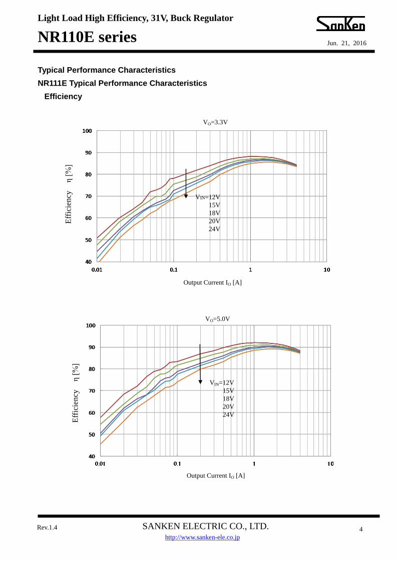
Typical Performance Characteristics
NR111E Typical Performance Characteristics
Efficiency
Eff
icie
ncy
η [
%]
Output Current IO [A]
VIN=12V
15V
18V
20V
24V
VO=3.3V
VO=5.0V
Eff
icie
ncy
η [
%]
Output Current IO [A]
VIN=12V
15V
18V
20V
24V
Light Load High Efficiency, 31V, Buck Regulator
NR110E series
SANKEN ELECTRIC CO., LTD.
Jun. 21, 2016
Rev.1.4 5
http://www.sanken-ele.co.jp
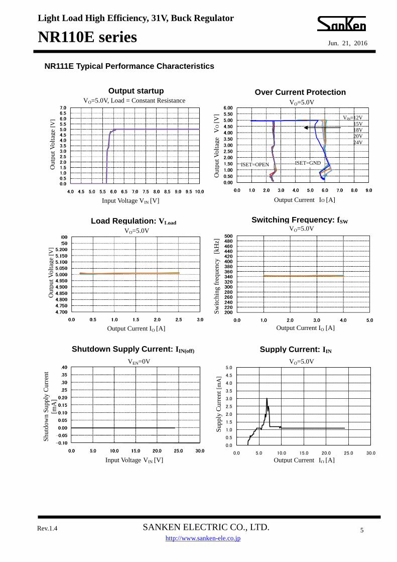
NR111E Typical Performance Characteristics
ISET=OPEN
Over Current Protection Output startup
VEN=0V
VO=5.0V
VO=5.0V, Load = Constant Resistance VO=5.0V
Ou
tpu
t V
olt
age
[V]
Input Voltage VIN [V]
Output Current IO [A]
Input Voltage VIN [V]
Ou
tpu
t V
olt
age
[V]
Output Current IO [A]
Ou
tpu
t V
olt
age
VO
[V
]
VIN=12V
15V
18V 20V
24V
Output Current IO [A]
Sw
itch
ing
fre
qu
ency
[k
Hz]
Sh
utd
ow
n S
upp
ly C
urr
ent
[mA
]
0.0
0.5
1.0
1.5
2.0
2.5
3.0
3.5
4.0
4.5
5.0
0.0 5.0 10.0 15.0 20.0 25.0 30.0
Iin [
mA
]
VIN[V]
NR114K/115K,NR116K,NR117K IQ VO=5.0V
Su
pp
ly C
urr
ent
[mA
]
Shutdown Supply Current: IIN(off) Supply Current: IIN
Switching Frequency: fSW Load Regulation: VLoad
Output Current IO [A]
VO=5.0V
ISET=GND
Light Load High Efficiency, 31V, Buck Regulator
NR110E series
SANKEN ELECTRIC CO., LTD.
Jun. 21, 2016
Rev.1.4 6
http://www.sanken-ele.co.jp
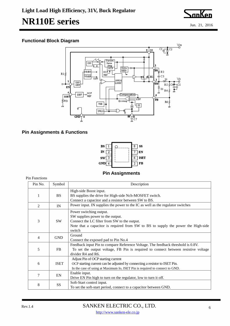
Functional Block Diagram
Pin Assignments & Functions
Pin Assignments
Pin Functions
Pin No. Symbol Description
1 BS
High-side Boost input.
BS supplies the drive for High-side Nch-MOSFET switch.
Connect a capacitor and a resistor between SW to BS.
2 IN Power input. IN supplies the power to the IC as well as the regulator switches
3 SW
Power switching output.
SW supplies power to the output.
Connect the LC filter from SW to the output.
Note that a capacitor is required from SW to BS to supply the power the High-side
switch
4 GND Ground
Connect the exposed pad to Pin No.4
5 FB
Feedback input Pin to compare Reference Voltage. The feedback threshold is 0.8V.
To set the output voltage, FB Pin is required to connect between resistive voltage
divider R4 and R6.
6 ISET
Adjust Pin of OCP starting current
OCP starting current can be adjusted by connecting a resistor to ISET Pin.
In the case of using at Maximum Io, ISET Pin is required to connect to GND.
7 EN Enable input.
Drive EN Pin high to turn on the regulator, low to turn it off.
8 SS Soft-Start control input.
To set the soft-start period, connect to a capacitor between GND.
Light Load High Efficiency, 31V, Buck Regulator
NR110E series
SANKEN ELECTRIC CO., LTD.
Jun. 21, 2016
Rev.1.4 7
http://www.sanken-ele.co.jp
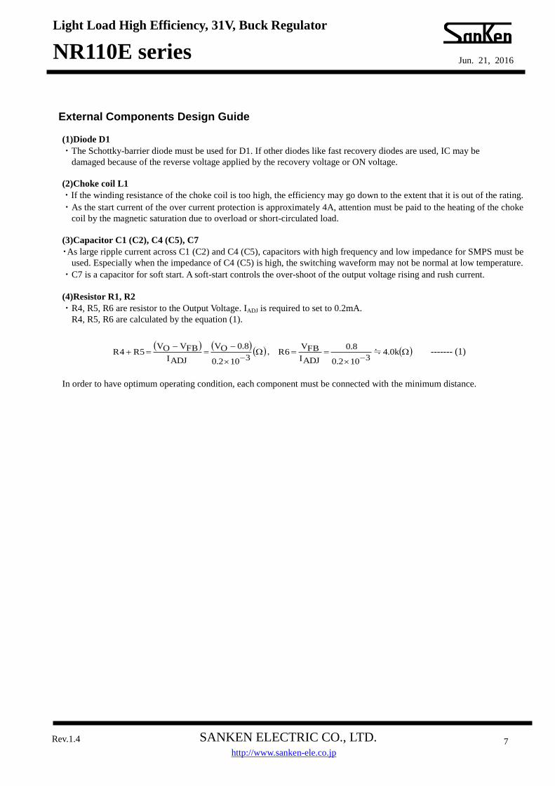
External Components Design Guide
(1)Diode D1
・The Schottky-barrier diode must be used for D1. If other diodes like fast recovery diodes are used, IC may be
damaged because of the reverse voltage applied by the recovery voltage or ON voltage.
(2)Choke coil L1
・If the winding resistance of the choke coil is too high, the efficiency may go down to the extent that it is out of the rating.
・As the start current of the over current protection is approximately 4A, attention must be paid to the heating of the choke
coil by the magnetic saturation due to overload or short-circulated load.
(3)Capacitor C1 (C2), C4 (C5), C7
・As large ripple current across C1 (C2) and C4 (C5), capacitors with high frequency and low impedance for SMPS must be
used. Especially when the impedance of C4 (C5) is high, the switching waveform may not be normal at low temperature.
・C7 is a capacitor for soft start. A soft-start controls the over-shoot of the output voltage rising and rush current.
(4)Resistor R1, R2
・R4, R5, R6 are resistor to the Output Voltage. IADJ is required to set to 0.2mA.
R4, R5, R6 are calculated by the equation (1).
------- (1)
In order to have optimum operating condition, each component must be connected with the minimum distance.
k0.4
3102.0
8.0
ADJI
FBV6R
3102.0
8.0OV
ADJI
FBVOV5R4R ≒,

Light Load High Efficiency, 31V, Buck Regulator
NR110E series
SANKEN ELECTRIC CO., LTD.
Jun. 21, 2016
Rev.1.4 8
http://www.sanken-ele.co.jp
Allowable package power dissipation
NOTES
1) Glass-epoxy board mounting in a 30×30mm
2) Copper area: 25×25mm
3) The power dissipation is calculated at the junction temperature 125 °C
4) Losses can be calculated by the following equation.
As the efficiency is subject to the input voltage and output current, it shall be obtained from the efficiency curve and
substituted in percent
5) Thermal design for D1 shall be made separately.
INV
OV1OIFV1
x
100OIOVDP
VO: Output voltage
VIN: Input voltage
IO: Output current
ηx: Efficiency(%)
VF: Diode forward voltage
SJPB-L4…0.55V(IO=3A)
Light Load High Efficiency, 31V, Buck Regulator
NR110E series
SANKEN ELECTRIC CO., LTD.
Jun. 21, 2016
Rev.1.4 9
http://www.sanken-ele.co.jp
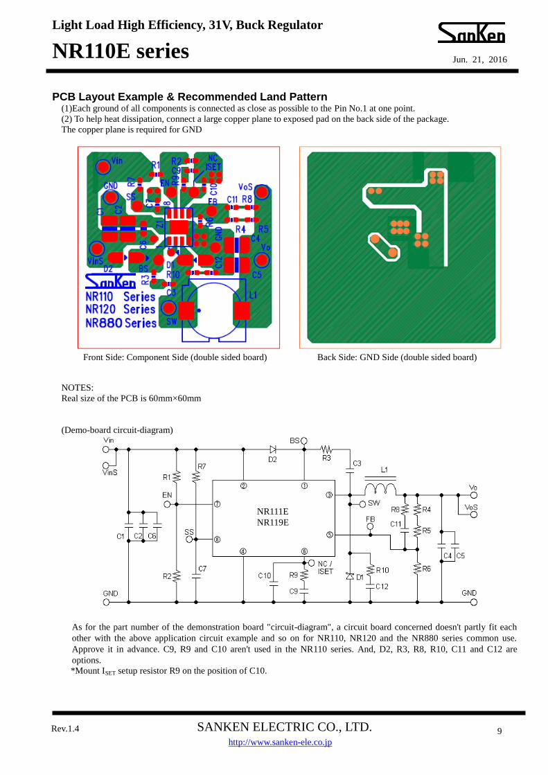
PCB Layout Example & Recommended Land Pattern (1)Each ground of all components is connected as close as possible to the Pin No.1 at one point.
(2) To help heat dissipation, connect a large copper plane to exposed pad on the back side of the package.
The copper plane is required for GND
NOTES:
Real size of the PCB is 60mm×60mm
(Demo-board circuit-diagram)
As for the part number of the demonstration board "circuit-diagram", a circuit board concerned doesn't partly fit each
other with the above application circuit example and so on for NR110, NR120 and the NR880 series common use.
Approve it in advance. C9, R9 and C10 aren't used in the NR110 series. And, D2, R3, R8, R10, C11 and C12 are
options.
*Mount ISET setup resistor R9 on the position of C10.
Front Side: Component Side (double sided board) Back Side: GND Side (double sided board)
NR111E
NR119E
Light Load High Efficiency, 31V, Buck Regulator
NR110E series
SANKEN ELECTRIC CO., LTD.
Jun. 21, 2016
Rev.1.4 10
http://www.sanken-ele.co.jp
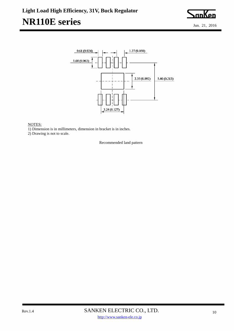
NOTES:
1) Dimension is in millimeters, dimension in bracket is in inches.
2) Drawing is not to scale.
Recommended land pattern
Light Load High Efficiency, 31V, Buck Regulator
NR110E series
SANKEN ELECTRIC CO., LTD.
Jun. 21, 2016
Rev.1.4 11
http://www.sanken-ele.co.jp
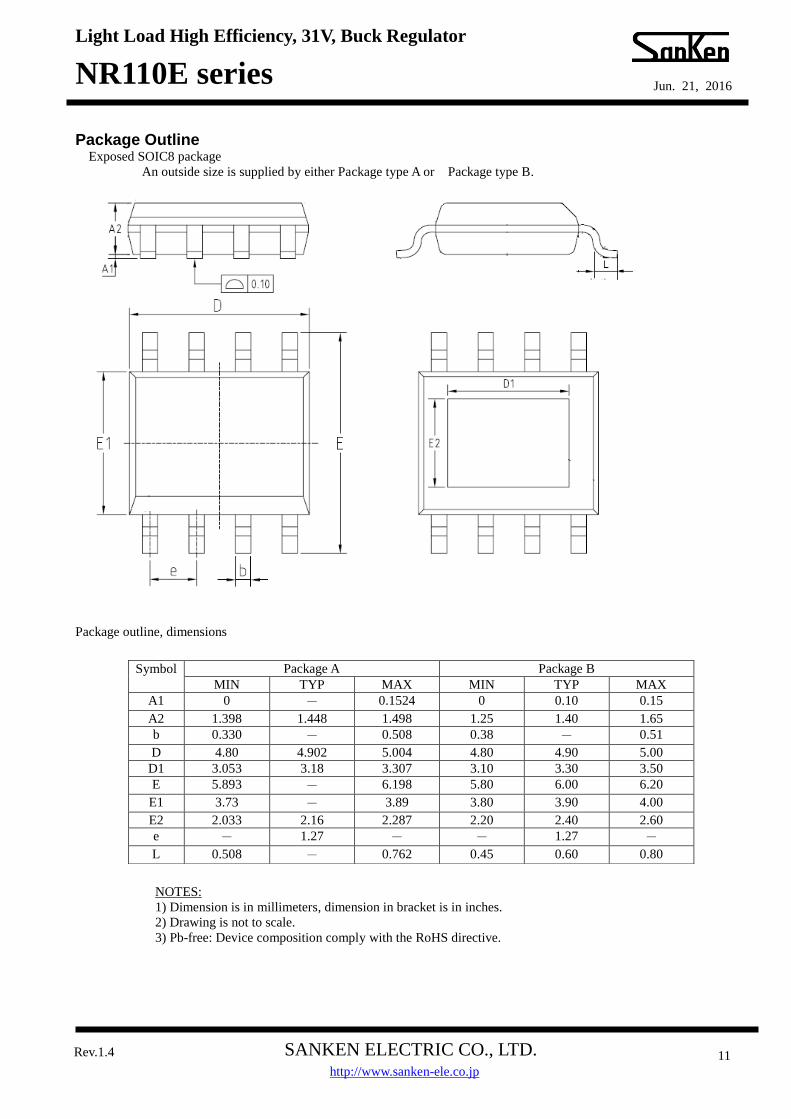
Package Outline Exposed SOIC8 package
An outside size is supplied by either Package type A or Package type B.
Package outline, dimensions
NOTES:
1) Dimension is in millimeters, dimension in bracket is in inches.
2) Drawing is not to scale.
3) Pb-free: Device composition comply with the RoHS directive.
Symbol Package A Package B
MIN TYP MAX MIN TYP MAX
A1 0 - 0.1524 0 0.10 0.15
A2 1.398 1.448 1.498 1.25 1.40 1.65
b 0.330 - 0.508 0.38 - 0.51
D 4.80 4.902 5.004 4.80 4.90 5.00
D1 3.053 3.18 3.307 3.10 3.30 3.50
E 5.893 - 6.198 5.80 6.00 6.20
E1 3.73 - 3.89 3.80 3.90 4.00
E2 2.033 2.16 2.287 2.20 2.40 2.60
e - 1.27 - - 1.27 -
L 0.508 - 0.762 0.45 0.60 0.80
Light Load High Efficiency, 31V, Buck Regulator
NR110E series
SANKEN ELECTRIC CO., LTD.
Jun. 21, 2016
Rev.1.4 12
http://www.sanken-ele.co.jp
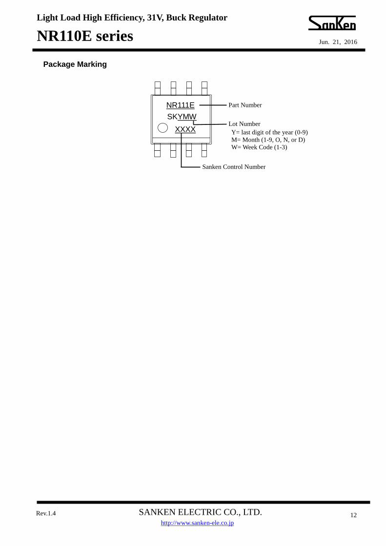
Package Marking
NR111E
SKYMW
Part Number
Lot Number
Sanken Control Number
Y= last digit of the year (0-9)
M= Month (1-9, O, N, or D)
W= Week Code (1-3)
XXXX
Light Load High Efficiency, 31V, Buck Regulator
NR110E series
SANKEN ELECTRIC CO., LTD.
Jun. 21, 2016
Rev.1.4 13
http://www.sanken-ele.co.jp
IMPORTANT NOTES
● All data, illustrations, graphs, tables and any other information included in this document as to Sanken’s products listed herein (the
“Sanken Products”) are current as of the date this document is issued. All contents in this document are subject to any change without
notice due to improvement of the Sanken Products, etc. Please make sure to confirm with a Sanken sales representative that the contents
set forth in this document reflect the latest revisions before use.
● The Sanken Products are intended for use as components of general purpose electronic equipment or apparatus (such as home appliances,
office equipment, telecommunication equipment, measuring equipment, etc.). Prior to use of the Sanken Products, please put your
signature, or affix your name and seal, on the specification documents of the Sanken Products and return them to Sanken. When
considering use of the Sanken Products for any applications that require higher reliability (such as transportation equipment and its
control systems, traffic signal control systems or equipment, disaster/crime alarm systems, various safety devices, etc.), you must contact
a Sanken sales representative to discuss the suitability of such use and put your signature, or affix your name and seal, on the
specification documents of the Sanken Products and return them to Sanken, prior to the use of the Sanken Products. The Sanken Products
are not intended for use in any applications that require extremely high reliability such as: aerospace equipment; nuclear power control
systems; and medical equipment or systems, whose failure or malfunction may result in death or serious injury to people, i.e., medical
devices in Class III or a higher class as defined by relevant laws of Japan (collectively, the “Specific Applications”). Sanken assumes no
liability or responsibility whatsoever for any and all damages and losses that may be suffered by you, users or any third party, resulting
from the use of the Sanken Products in the Specific Applications or in manner not in compliance with the instructions set forth herein. ● In the event of using the Sanken Products by either (i) combining other products or materials therewith or (ii) physically, chemically or
otherwise processing or treating the same, you must duly consider all possible risks that may result from all such uses in advance and
proceed therewith at your own responsibility. ● Although Sanken is making efforts to enhance the quality and reliability of its products, it is impossible to completely avoid the
occurrence of any failure or defect in semiconductor products at a certain rate. You must take, at your own responsibility, preventative
measures including using a sufficient safety design and confirming safety of any equipment or systems in/for which the Sanken Products
are used, upon due consideration of a failure occurrence rate or derating, etc., in order not to cause any human injury or death, fire
accident or social harm which may result from any failure or malfunction of the Sanken Products. Please refer to the relevant
specification documents and Sanken’s official website in relation to derating. ● No anti-radioactive ray design has been adopted for the Sanken Products. ● No contents in this document can be transcribed or copied without Sanken’s prior written consent. ● The circuit constant, operation examples, circuit examples, pattern layout examples, design examples, recommended examples, all
information and evaluation results based thereon, etc., described in this document are presented for the sole purpose of reference of use
of the Sanken Products and Sanken assumes no responsibility whatsoever for any and all damages and losses that may be suffered by you,
users or any third party, or any possible infringement of any and all property rights including intellectual property rights and any other
rights of you, users or any third party, resulting from the foregoing. ● All technical information described in this document (the “Technical Information”) is presented for the sole purpose of reference of use
of the Sanken Products and no license, express, implied or otherwise, is granted hereby under any intellectual property rights or any other
rights of Sanken. ● Unless otherwise agreed in writing between Sanken and you, Sanken makes no warranty of any kind, whether express or implied,
including, without limitation, any warranty (i) as to the quality or performance of the Sanken Products (such as implied warranty of
merchantability, or implied warranty of fitness for a particular purpose or special environment), (ii) that any Sanken Product is delivered
free of claims of third parties by way of infringement or the like, (iii) that may arise from course of performance, course of dealing or
usage of trade, and (iv) as to any information contained in this document (including its accuracy, usefulness, or reliability). ● In the event of using the Sanken Products, you must use the same after carefully examining all applicable environmental laws and
regulations that regulate the inclusion or use of any particular controlled substances, including, but not limited to, the EU RoHS
Directive, so as to be in strict compliance with such applicable laws and regulations. ● You must not use the Sanken Products or the Technical Information for the purpose of any military applications or use, including but not
limited to the development of weapons of mass destruction. In the event of exporting the Sanken Products or the Technical Information,
or providing them for non-residents, you must comply with all applicable export control laws and regulations in each country including
the U.S. Export Administration Regulations (EAR) and the Foreign Exchange and Foreign Trade Act of Japan, and follow the procedures
required by such applicable laws and regulations. ● Sanken assumes no responsibility for any troubles, which may occur during the transportation of the Sanken Products including the
falling thereof, out of Sanken’s distribution network. ● Although Sanken has prepared this document with its due care to pursue the accuracy thereof, Sanken does not warrant that it is error
free and Sanken assumes no liability whatsoever for any and all damages and losses which may be suffered by you resulting from any
possible errors or omissions in connection with the contents included herein. ● Please refer to the relevant specification documents in relation to particular precautions when using the Sanken Products, and refer to our
official website in relation to general instructions and directions for using the Sanken Products.
DSGN-CEZ-16001