light antiarmor weapons - bits
TRANSCRIPT
*FM 3-23.25
i
FIELD MANUAL HEADQUARTERSNO. 3-23.25 (FM 23-25) DEPARTMENT OF THE ARMY
WASHINGTON, DC, 30 August 2001
LIGHT ANTIARMOR WEAPONS
CONTENTS
PagePreface................................................................................................................................iiiCHAPTER 1. INTRODUCTION
1-1. Types of Light Antiarmor Weapons.............................................1-11-2. Care and Handling........................................................................1-21-3. Destruction Procedures (Combat Only) .......................................1-21-4. Decontamination Procedures .......................................................1-31-5. Operating Temperatures...............................................................1-4
CHAPTER 2. M72-SERIES LAW, OPERATION AND FUNCTION2-1. Description ...................................................................................2-12-2. Technical Data .............................................................................2-22-3. Ammunition .................................................................................2-22-4. Inspection .....................................................................................2-52-5. Firing Mechanism ........................................................................2-62-6. Sights............................................................................................2-72-7. Operation and Function..............................................................2-112-8. Misfire Procedures .....................................................................2-142-9. Restoration to Carrying Configuration.......................................2-14
CHAPTER 3. M136 AT4, OPERATION AND FUNCTION3-1. Description ...................................................................................3-13-2. Technical Data .............................................................................3-23-3. Ammunition .................................................................................3-23-4. Inspection .....................................................................................3-43-5. Firing Mechanism, Safeties, and Weapon Function ....................3-53-6. Sights............................................................................................3-73-7. Operation......................................................................................3-83-8. Misfire Procedures .....................................................................3-113-9. Restoration to Carrying Configuration.......................................3-13
DISTRIBUTION RESTRICTION: Approved for public release; distribution is unlimited.______________________________________________________*This publication supersedes FM 23-25, 17 August 1994.
FM 3-23.25
ii
PageCHAPTER 4. MARKSMANSHIP FUNDAMENTALS
4-1. Steady Hold ..................................................................................4-14-2. Aiming Procedures.......................................................................4-14-3. Breath Control ..............................................................................4-64-4. Trigger Manipulation ...................................................................4-64-5. Integrated Act of Shooting ...........................................................4-6
CHAPTER 5. FIRING POSITIONS5-1. Standing Position .........................................................................5-15-2. Kneeling Position .........................................................................5-35-3. Sitting Position .............................................................................5-45-4. Prone Position ..............................................................................5-5
CHAPTER 6. COMBAT TECHNIQUES6-1. Range Estimation .........................................................................6-16-2. Speed Estimation..........................................................................6-16-3. Armored Vehicle Weaknesses .....................................................6-26-4. Methods of Engagement...............................................................6-46-5. Engagement of Field Fortifications and Buildings ......................6-76-6. Engagement of Other Vehicles ....................................................6-76-7. Limited Visibility Engagements ..................................................6-96-8. Engagement in NBC Conditions ..................................................6-96-9. Engagement from an Enclosure ...................................................6-96-10. Engagement Beyond Maximum Effective Range
(M136 AT4 Only) ......................................................................6-106-11. Offensive Operations..................................................................6-106-12. Defensive Operations .................................................................6-116-13. Other Tactical Operations ..........................................................6-11
CHAPTER 7. TRAIN-THE-TRAINER AND UNIT TRAINING PROGRAMS7-1. Train-the-Trainer Program...........................................................7-17-2. Unit Training Program .................................................................7-27-3. Training Strategy..........................................................................7-4
APPENDIX A. SAFETY...............................................................................................A-1APPENDIX B. TRAINING DEVICES AND AIDS..................................................... B-1APPENDIX C. PERFORMANCE EVALUATIONS ................................................... C-1APPENDIX D. SUGGESTED DESIGN FOR COMBINED LIGHT
ANTIARMOR RANGE.......................................................................D-1APPENDIX E. FIRING TABLES AND EXAMPLE SCORECARDS........................ E-1APPENDIX F. INFRARED LASER AIMING DEVICES ...........................................F-1GLOSSARY.........................................................................................................Glossary-1REFERENCES................................................................................................. References-1INDEX ......................................................................................................................Index-1
FM 3-23.25 (FM 23-25)30 AUGUST 2001
DISTR
Activeaccord
By Order of the Secretary of the Army:
ERIC K. SHINSEKIGeneral, United States Army
Chief of StaffOfficial:
AdmS
JOEL B. HUDSONinistrative Assistant to theecretary of the Army
0122206
IBUTION:
Army, Army National Guard, and U. S. Army Reserve: To be distributed inance with the initial distribution number 114321, requirements for FM 3-23.25.
FM 3-23.25
1-1
CHAPTER 1INTRODUCTION
This chapter provides information common to the light antiarmorweapons discussed in this manual. Topics include care and handling,destruction and decontamination procedures, and operating temperatures.Light antiarmor weapons are used against light armored vehicles, fieldfortifications, or other similar targets. These weapons are issued as roundsof ammunition to individual soldiers in addition to their assigned weaponsand the unit's organic antiarmor weapons. Light antiarmor weapons canwithstand extreme weather and environmental conditions, including arctic,tropical, and desert. The light antiarmor weapons category includes bothlight antiarmor and light antitank weapons.
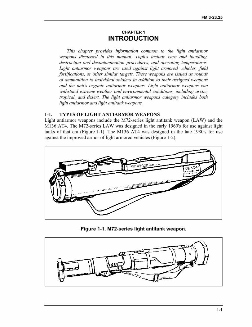
1-1. TYPES OF LIGHT ANTIARMOR WEAPONSLight antiarmor weapons include the M72-series light antitank weapon (LAW) and theM136 AT4. The M72-series LAW was designed in the early 1960's for use against lighttanks of that era (Figure 1-1). The M136 AT4 was designed in the late 1980's for useagainst the improved armor of light armored vehicles (Figure 1-2).
Figure 1-1. M72-series light antitank weapon.
FM 3-23.25
1-2
Figure 1-2. M136 AT4 light antiarmor weapon.
1-2. CARE AND HANDLINGLight antiarmor weapons are issued as rounds of ammunition. The only requirement fortheir care is a visual inspection, outlined in the appropriate chapter for each weapon(Chapter 2 for the LAW and Chapter 3 for the AT4).
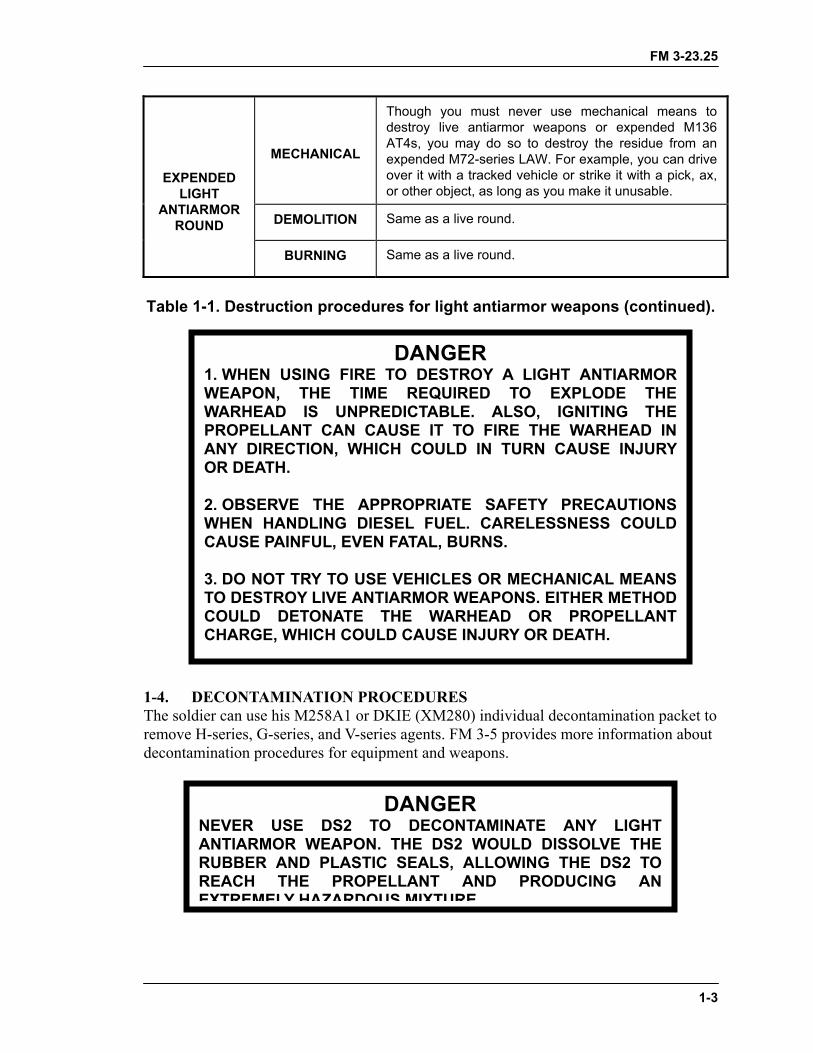
1-3. DESTRUCTION PROCEDURES (COMBAT ONLY)In combat, live and expended light antiarmor weapons are destroyed only to prevent theircapture or use by the enemy and, even then, only on order. For such an order to be given,the weapons must be so badly damaged that neither repairs nor cannibalization canrestore them to usable condition (FM 5-25). Table 1-1 provides destruction proceduresfor live and expended light antiarmor weapons; Appendix A discusses safety precautionsto follow when destroying them.
DEMOLITION
Pcca
BURNING
Cmtoswdo
LIVELIGHT
ANTIARMORROUND
FIRING
Ifddo
TO AVOID POSSIBLESAFE POSITION ANANY DESTRUCTIONDEMOLITIONS FOR THE PROPER PROCE
Table 1-1. Destruction pro
DANGER INJURY OR DEATH, MOVE TO A
D TAKE COVER BEFORE USING PROCEDURE. BEFORE USINGANY REASON, YOU MUST KNOWDURES IN FM 5-25.
repare a 113-gram (one-quarter pound) demolitionharge. Tape or tie the charge over the propellantharge. Dual prime the charge to reduce the chance of misfire.
onstruct a pit or trench deep enough to allow 0.6eter (2 feet) of space between the weapons and thep surface of the ground. Place combustible material
uch as wood, paper, or rags in the pit, then place theeapon inside, pointed into the side of the pit andirected away from all friendly soldiers. Pour diesel fuelr oil over the weapons and the combustible material.
time does not permit use of the previous methods,ispose of the weapons by firing them randomly in theirection of the enemy. Before using this method,bserve all appropriate safety requirements.
cedures for light antiarmor weapons.
FM 3-23.25
MECHANICAL
Though you must never use mechanical means todestroy live antiarmor weapons or expended M136AT4s, you may do so to destroy the residue from anexpended M72-series LAW. For example, you can driveover it with a tracked vehicle or strike it with a pick, ax,or other object, as long as you make it unusable.
DEMOLITION Same as a live round.
EXPENDEDLIGHT
ANTIARMORROUND
BURNING Same as a live round.
Table 1-1. Destruction procedures for light antiarmor weapons (continued).
1-4. DECONTAMINATION PROCEDURESThe soldier can use his M258A1 or DKIE (XM280) individual decontamination packet toremove H-series, G-series, and V-series agents. FM 3-5 provides more information aboutdecontamination procedures for equipment and weapons.
DANGER1. WHEN USING FIRE TO DESTROY A LIGHT ANTIARMORWEAPON, THE TIME REQUIRED TO EXPLODE THEWARHEAD IS UNPREDICTABLE. ALSO, IGNITING THEPROPELLANT CAN CAUSE IT TO FIRE THE WARHEAD INANY DIRECTION, WHICH COULD IN TURN CAUSE INJURYOR DEATH.
2. OBSERVE THE APPROPRIATE SAFETY PRECAUTIONSWHEN HANDLING DIESEL FUEL. CARELESSNESS COULDCAUSE PAINFUL, EVEN FATAL, BURNS.
3. DO NOT TRY TO USE VEHICLES OR MECHANICAL MEANSTO DESTROY LIVE ANTIARMOR WEAPONS. EITHER METHODCOULD DETONATE THE WARHEAD OR PROPELLANTCHARGE, WHICH COULD CAUSE INJURY OR DEATH.
NEVER USE DS2 TANTIARMOR WEAPONRUBBER AND PLASTICREACH THE PROPEXTREMELY HAZARDO
DANGERO DECONTAMINATE ANY LIGHT. THE DS2 WOULD DISSOLVE THE
SEALS, ALLOWING THE DS2 TOELLANT AND PRODUCING ANUS MIXTURE
1-3

FM 3-23.25
1-4
1-5. OPERATING TEMPERATURESOperating temperatures for the M72-series LAW and M136 AT4 are -40 degrees to 140degrees Fahrenheit (-40 degrees to 60 degrees Centigrade). Firing light antiarmorweapons in temperatures outside these limits could cause a misfire or produce some otherhazard for the soldier (Appendix A).
FM 3-23.25
2-1
CHAPTER 2M72-SERIES LAW, OPERATION AND FUNCTION
This chapter provides information on and technical data for theM72-series light antitank weapon (LAW). It also discusses thecharacteristics, nomenclature, functioning, and operation of the LAW.
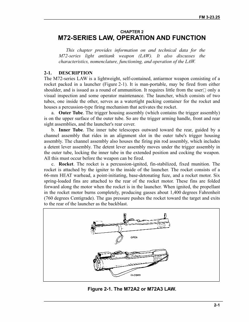
2-1. DESCRIPTIONThe M72-series LAW is a lightweight, self-contained, antiarmor weapon consisting of arocket packed in a launcher (Figure 2-1). It is man-portable, may be fired from eithershoulder, and is issued as a round of ammunition. It requires little from the user only avisual inspection and some operator maintenance. The launcher, which consists of twotubes, one inside the other, serves as a watertight packing container for the rocket andhouses a percussion-type firing mechanism that activates the rocket.
a. Outer Tube. The trigger housing assembly (which contains the trigger assembly)is on the upper surface of the outer tube. So are the trigger arming handle, front and rearsight assemblies, and the launcher's rear cover.
b. Inner Tube. The inner tube telescopes outward toward the rear, guided by achannel assembly that rides in an alignment slot in the outer tube's trigger housingassembly. The channel assembly also houses the firing pin rod assembly, which includesa detent lever assembly. The detent lever assembly moves under the trigger assembly inthe outer tube, locking the inner tube in the extended position and cocking the weapon.All this must occur before the weapon can be fired.
c. Rocket. The rocket is a percussion-ignited, fin-stabilized, fixed munition. Therocket is attached by the igniter to the inside of the launcher. The rocket consists of a66-mm HEAT warhead, a point-initiating, base-detonating fuze, and a rocket motor. Sixspring-loaded fins are attached to the rear of the rocket motor. These fins are foldedforward along the motor when the rocket is in the launcher. When ignited, the propellantin the rocket motor burns completely, producing gasses about 1,400 degrees Fahrenheit(760 degrees Centigrade). The gas pressure pushes the rocket toward the target and exitsto the rear of the launcher as the backblast.
Figure 2-1. The M72A2 or M72A3 LAW.
FM 3-23.25
2-2
2-2. TECHNICAL DATAThe following data apply to the M72A2 and M72A3 LAWs:
a. Launcher.Length (Extended).................................................Less than 1 meter (34.67 inches)Length (Closed).................................................................. 0.67 meter (24.8 inches)Weight (Complete M72A2)........................................................2.3 kg (5.1 pounds)Weight (Complete M72A3)........................................................2.5 kg (5.5 pounds)Firing Mechanism ....................................................................................PercussionFront Sight.....................................Reticle graduated in 25-meter range incrementsRear Sight.......................... Peep sight adjusts automatically to temperature change
b. Rocket.Caliber ............................................................................................................ 66 mmLength........................................................................................ 50.8 cm (20 inches)Weight ........................................................................................1.8 kg (2.2 pounds)
Muzzle Velocity......................................................................... 144.8 mps (475 fps) Minimum Range (Combat) .........................................................10 meters (33 feet) Minimum Arming Range ............................................................10 meters (33 feet)
Maximum Range ...............................................................1,000 meters (3,300 feet) Maximum Effective Ranges:
Stationary Target ...............................................................200 meters (660 feet)Moving Target ...................................................................165 meters (541 feet)
(Beyond these ranges, there is less than a fifty percentchance of hitting the target.)
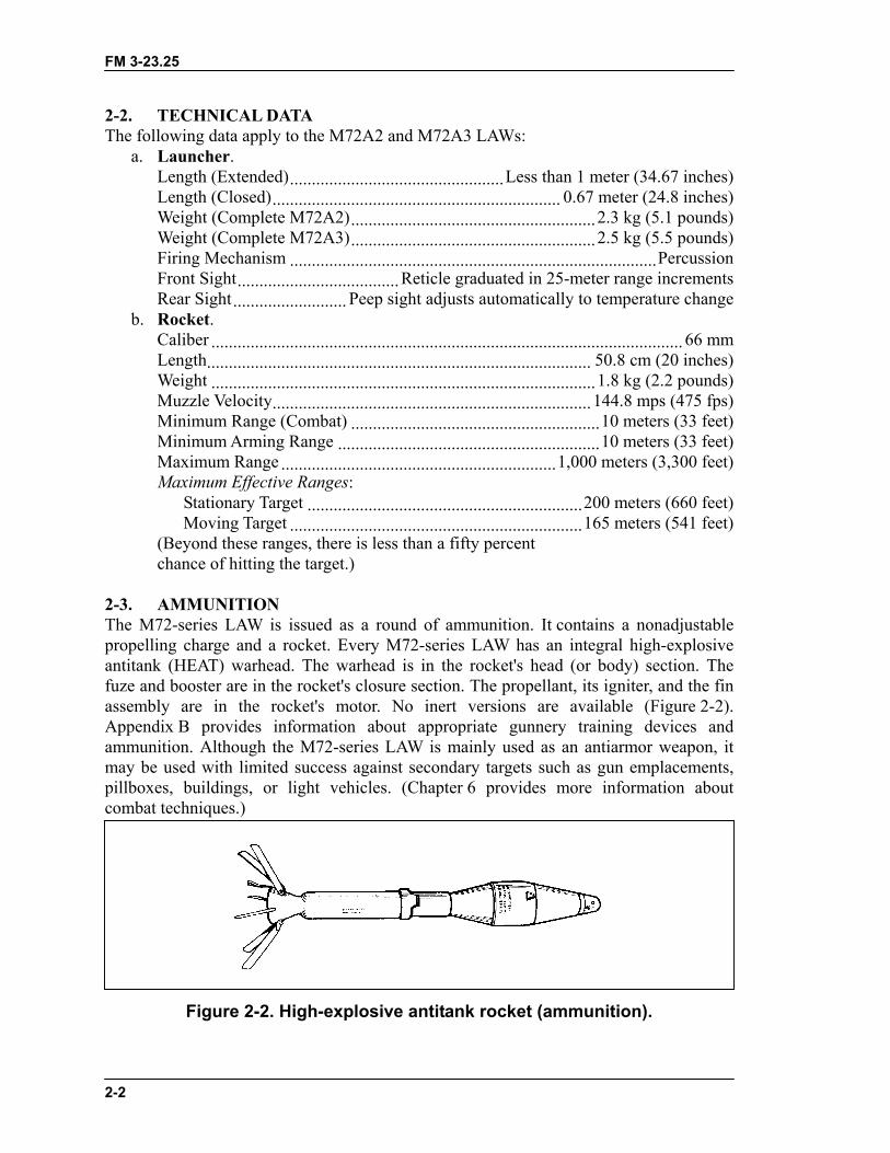
2-3. AMMUNITIONThe M72-series LAW is issued as a round of ammunition. It contains a nonadjustablepropelling charge and a rocket. Every M72-series LAW has an integral high-explosiveantitank (HEAT) warhead. The warhead is in the rocket's head (or body) section. Thefuze and booster are in the rocket's closure section. The propellant, its igniter, and the finassembly are in the rocket's motor. No inert versions are available (Figure 2-2).Appendix B provides information about appropriate gunnery training devices andammunition. Although the M72-series LAW is mainly used as an antiarmor weapon, itmay be used with limited success against secondary targets such as gun emplacements,pillboxes, buildings, or light vehicles. (Chapter 6 provides more information aboutcombat techniques.)
Figure 2-2. High-explosive antitank rocket (ammunition).
FM 3-23.25
2-3
a. Description. The 66-mm HEAT rocket warhead consists of a tapered, thin-gaugesteel body. When it explodes, the force and heat of the explosive focus into a small butpowerful gas jet. This directional jet penetrates the target and, if the target is a vehicle,sprays molten metal inside. If the jet hits an engine or ammunition, it may start a fire orcause an explosion. Figure 2-3 shows how the warhead penetrates 300 millimeters ofrolled homogeneous steel armor.
(1) Impact. The nose cone crushes; the impact sensor activates the fuze.(2) Ignition. The ogive crush switch activates the electric detonator. The booster
detonates, initiating the main charge.(3) Penetration. The main charge fires and forces the warhead body liner into a
directional gas jet that penetrates armor plate.(4) After Armor Effects (Spalling). The projectile fragments and incendiary effects
produce blinding light and destroy the target's interior.
Figure 2-3. Effects of M72-series LAW warhead.
b. Characteristics. The head of the round is olive drab stenciled in yellow. TheM412 fuze is dropsafe and boresafe. Its minimum arming distance is about 33 feet(10 meters). Six stabilizing fins are attached as part of the motor. As the rocket clears thelauncher, springs force open the fins, which stabilize the rocket in flight.
c. Packaging. Five complete M72-series LAWs are packaged within a fiberboardinner pack for a total weight of 12.5 kilograms (27 1/2 pounds). Three inner packs arethen placed in a wire-bound wooden box, the gross weight of which is 54.5 kilograms(120 pounds) (Figure 2-4, page 2-4).
FM 3-23.25
2-4
Figure 2-4. Packaging for M72-series LAW.
2-4. INSPECTIONBecause the M72-series LAW is issued as a round of ammunition rather than as aweapon, inspection is limited to a visual examination of the sealed unit.Inspect the launcher's overall condition before preparing the launcher for use.
• Check the body for dents, cracks, or bulges.• Check the rubber boots covering the trigger bar and barrel detent for tears or
punctures.• Ensure the arming handle is present and on SAFE and that the pull pin is in
place.
FM 3-23.25
2-5
• Check the data plate for the phrase, W/COUPLER (Figure 2-5).
Figure 2-5. Launcher data plate.
DANGER1. IF THE M72A2 LAW DOES NOT STATE "W/COUPLER" ON ITSDATA PLATE, TURN THE WEAPON IN TO THE UNITAMMUNITION SECTION.
2. THE COUPLER PREVENTS THE INNER AND OUTER TUBESFROM SEPARATING AND POSSIBLY CAUSING PREMATUREDETONATION.
FM 3-23.25
2-6
2-5. FIRING MECHANISMThe firing mechanism includes the trigger arming handle, the trigger assembly, and thefiring pin rod assembly (Figure 2-6).
Figure 2-6. Firing mechanism.
a. Trigger Arming Handle. The trigger arming handle is located forward of thetrigger bar and has two positions: SAFE and ARM. Leave the trigger arming handle onSAFE until the launcher is in the correct firing position (Figure 2-7). To press the trigger,you must first pull the arming handle forward and lock it in the ARM position.
b. Trigger Assembly. The trigger assembly is on the top rear of the outer tube. Tofire the launcher, press downward on the trigger bar.
Figure 2-7. Trigger arming handle.
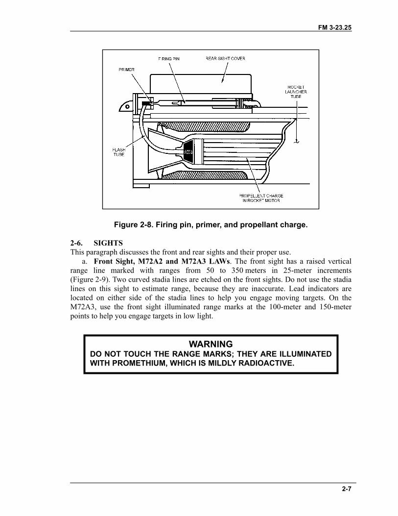
c. Firing Pin Rod Assembly. The rear sight cover and the firing pin housing are onthe top of the rear of the inner tube. Inside the housing, the primer and the firing pin rodare aligned (Figure 2-8). Pressing the trigger bar releases the tension on the firing pin rodassembly, allowing the firing pin to strike the center of the primer.
FM 3-23.25
2-7
Figure 2-8. Firing pin, primer, and propellant charge.
2-6. SIGHTSThis paragraph discusses the front and rear sights and their proper use.
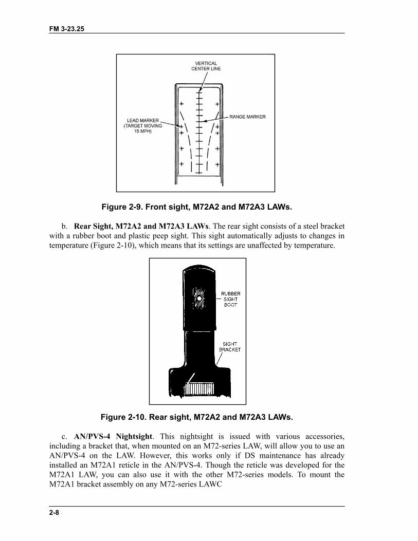
a. Front Sight, M72A2 and M72A3 LAWs. The front sight has a raised verticalrange line marked with ranges from 50 to 350 meters in 25-meter increments(Figure 2-9). Two curved stadia lines are etched on the front sights. Do not use the stadialines on this sight to estimate range, because they are inaccurate. Lead indicators arelocated on either side of the stadia lines to help you engage moving targets. On theM72A3, use the front sight illuminated range marks at the 100-meter and 150-meterpoints to help you engage targets in low light.
WARNINGDO NOT TOUCH THE RANGE MARKS; THEY ARE ILLUMINATEDWITH PROMETHIUM, WHICH IS MILDLY RADIOACTIVE.
FM 3-23.25
2-8
Figure 2-9. Front sight, M72A2 and M72A3 LAWs.
b. Rear Sight, M72A2 and M72A3 LAWs. The rear sight consists of a steel bracketwith a rubber boot and plastic peep sight. This sight automatically adjusts to changes intemperature (Figure 2-10), which means that its settings are unaffected by temperature.
Figure 2-10. Rear sight, M72A2 and M72A3 LAWs.
c. AN/PVS-4 Nightsight. This nightsight is issued with various accessories,including a bracket that, when mounted on an M72-series LAW, will allow you to use anAN/PVS-4 on the LAW. However, this works only if DS maintenance has alreadyinstalled an M72A1 reticle in the AN/PVS-4. Though the reticle was developed for theM72A1 LAW, you can also use it with the other M72-series models. To mount theM72A1 bracket assembly on any M72-series LAWC
FM 3-23.25
2-9
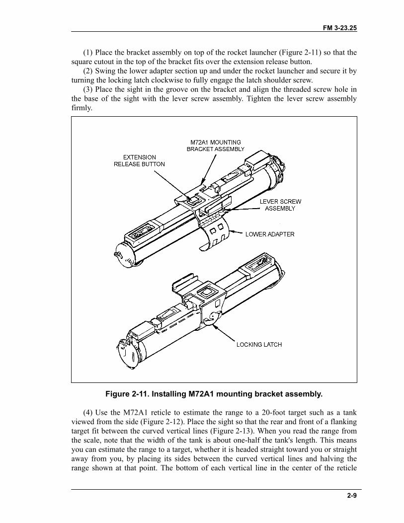
(1) Place the bracket assembly on top of the rocket launcher (Figure 2-11) so that thesquare cutout in the top of the bracket fits over the extension release button.
(2) Swing the lower adapter section up and under the rocket launcher and secure it byturning the locking latch clockwise to fully engage the latch shoulder screw.
(3) Place the sight in the groove on the bracket and align the threaded screw hole inthe base of the sight with the lever screw assembly. Tighten the lever screw assemblyfirmly.
Figure 2-11. Installing M72A1 mounting bracket assembly.
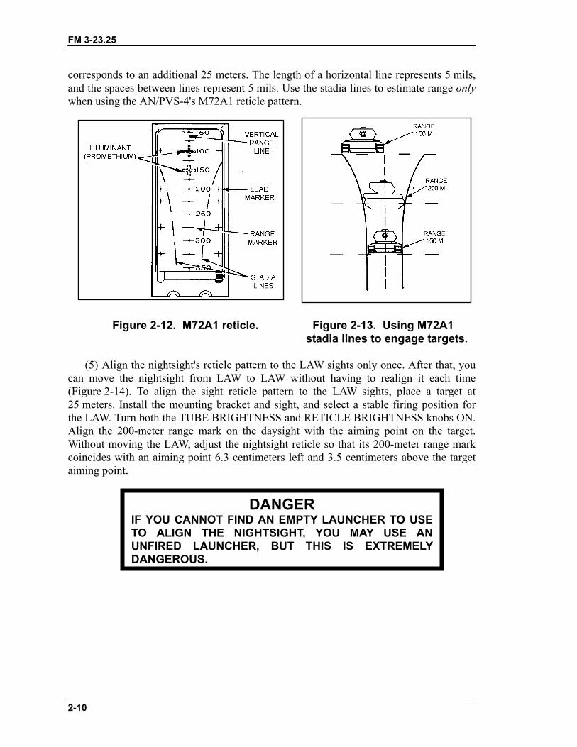
(4) Use the M72A1 reticle to estimate the range to a 20-foot target such as a tankviewed from the side (Figure 2-12). Place the sight so that the rear and front of a flankingtarget fit between the curved vertical lines (Figure 2-13). When you read the range fromthe scale, note that the width of the tank is about one-half the tank's length. This meansyou can estimate the range to a target, whether it is headed straight toward you or straightaway from you, by placing its sides between the curved vertical lines and halving therange shown at that point. The bottom of each vertical line in the center of the reticle
FM 3-23.25
2-10
corresponds to an additional 25 meters. The length of a horizontal line represents 5 mils,and the spaces between lines represent 5 mils. Use the stadia lines to estimate range onlywhen using the AN/PVS-4's M72A1 reticle pattern.
Figure 2-12. M72A1 reticle. Figure 2-13. Using M72A1 stadia lines to engage targets.
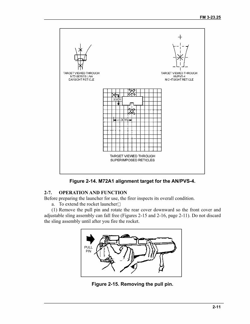
(5) Align the nightsight's reticle pattern to the LAW sights only once. After that, youcan move the nightsight from LAW to LAW without having to realign it each time(Figure 2-14). To align the sight reticle pattern to the LAW sights, place a target at25 meters. Install the mounting bracket and sight, and select a stable firing position forthe LAW. Turn both the TUBE BRIGHTNESS and RETICLE BRIGHTNESS knobs ON.Align the 200-meter range mark on the daysight with the aiming point on the target.Without moving the LAW, adjust the nightsight reticle so that its 200-meter range markcoincides with an aiming point 6.3 centimeters left and 3.5 centimeters above the targetaiming point.
IF YOU CANNOT FINTO ALIGN THE NIUNFIRED LAUNCHEDANGEROUS.
DANGERD AN EMPTY LAUNCHER TO USEGHTSIGHT, YOU MAY USE ANR, BUT THIS IS EXTREMELY
FM 3-23.25
2-11
Figure 2-14. M72A1 alignment target for the AN/PVS-4.
2-7. OPERATION AND FUNCTIONBefore preparing the launcher for use, the firer inspects its overall condition.
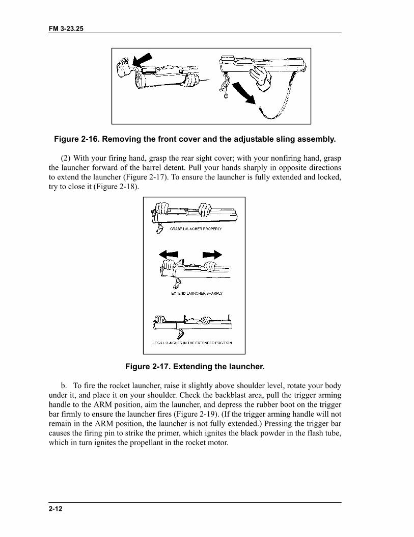
a. To extend the rocket launcher(1) Remove the pull pin and rotate the rear cover downward so the front cover and
adjustable sling assembly can fall free (Figures 2-15 and 2-16, page 2-11). Do not discardthe sling assembly until after you fire the rocket.
Figure 2-15. Removing the pull pin.
FM 3-23.25
2-12
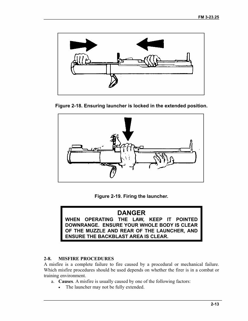
Figure 2-16. Removing the front cover and the adjustable sling assembly.
(2) With your firing hand, grasp the rear sight cover; with your nonfiring hand, graspthe launcher forward of the barrel detent. Pull your hands sharply in opposite directionsto extend the launcher (Figure 2-17). To ensure the launcher is fully extended and locked,try to close it (Figure 2-18).
Figure 2-17. Extending the launcher.
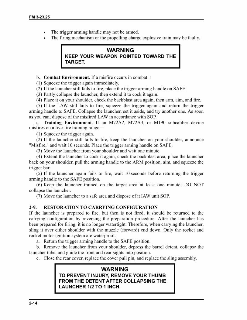
b. To fire the rocket launcher, raise it slightly above shoulder level, rotate your bodyunder it, and place it on your shoulder. Check the backblast area, pull the trigger arminghandle to the ARM position, aim the launcher, and depress the rubber boot on the triggerbar firmly to ensure the launcher fires (Figure 2-19). (If the trigger arming handle will notremain in the ARM position, the launcher is not fully extended.) Pressing the trigger barcauses the firing pin to strike the primer, which ignites the black powder in the flash tube,which in turn ignites the propellant in the rocket motor.
FM 3-23.25
Figure 2-18. Ensuring launcher is locked in the extended position.
Figure 2-19. Firing the launcher.
2-8. MISFIRE PROCEDURESA misfire is a complete failure to Which misfire procedures should betraining environment.
a. Causes. A misfire is usually c• The launcher may not be
WHEN OPERATING DOWNRANGE. ENSUOF THE MUZZLE ANDENSURE THE BACKB
DANGERTHE LAW, KEEP IT POINTED
RE YOUR WHOLE BODY IS CLEAR REAR OF THE LAUNCHER, AND
LAST AREA IS CLEAR.
2-13
fire caused by a procedural or mechanical failure. used depends on whether the firer is in a combat or
aused by one of the following factors:fully extended.
FM 3-23.25
2-14
• The trigger arming handle may not be armed.• The firing mechanism or the propelling charge explosive train may be faulty.
b. Combat Environment. If a misfire occurs in combat(1) Squeeze the trigger again immediately.(2) If the launcher still fails to fire, place the trigger arming handle on SAFE.(3) Partly collapse the launcher, then extend it to cock it again.(4) Place it on your shoulder, check the backblast area again, then arm, aim, and fire.(5) If the LAW still fails to fire, squeeze the trigger again and return the trigger
arming handle to SAFE. Collapse the launcher, set it aside, and try another one. As soonas you can, dispose of the misfired LAW in accordance with SOP.
c. Training Environment. If an M72A2, M72A3, or M190 subcaliber devicemisfires on a live-fire training range―
(1) Squeeze the trigger again.(2) If the launcher still fails to fire, keep the launcher on your shoulder, announce
"Misfire," and wait 10 seconds. Place the trigger arming handle on SAFE.(3) Move the launcher from your shoulder and wait one minute.(4) Extend the launcher to cock it again, check the backblast area, place the launcher
back on your shoulder, pull the arming handle to the ARM position, aim, and squeeze thetrigger bar.
(5) If the launcher again fails to fire, wait 10 seconds before returning the triggerarming handle to the SAFE position.
(6) Keep the launcher trained on the target area at least one minute; DO NOTcollapse the launcher.
(7) Move the launcher to a safe area and dispose of it IAW unit SOP.
2-9. RESTORATION TO CARRYING CONFIGURATIONIf the launcher is prepared to fire, but then is not fired, it should be returned to thecarrying configuration by reversing the preparation procedure. After the launcher hasbeen prepared for firing, it is no longer watertight. Therefore, when carrying the launcher,sling it over either shoulder with the muzzle (forward) end down. Only the rocket androcket motor ignition system are waterproof.
a. Return the trigger arming handle to the SAFE position.b. Remove the launcher from your shoulder, depress the barrel detent, collapse the
launcher tube, and guide the front and rear sights into position.c. Close the rear cover, replace the cover pull pin, and replace the sling assembly.
WARNINGKEEP YOUR WEAPON POINTED TOWARD THETARGET.
WARNINGTO PREVENT INJURY, REMOVE YOUR THUMBFROM THE DETENT AFTER COLLAPSING THELAUNCHER 1/2 TO 1 INCH.
FM 3-23.25
3-1
CHAPTER 3M136 AT4, OPERATION AND FUNCTION
This chapter provides information and technical data for the M136AT4 light antiarmor weapon, including its characteristics, nomenclature,and operation. Its function, firing mechanism, and safeties are alsodiscussed.
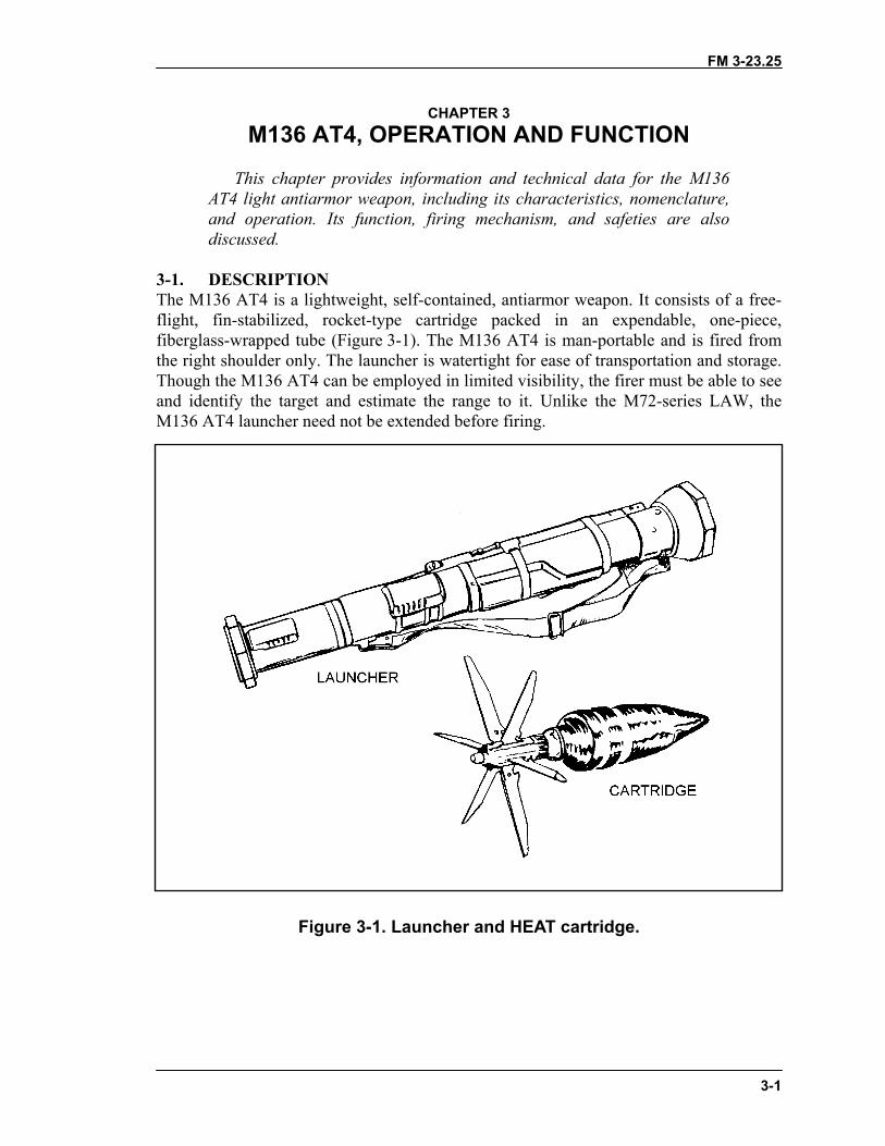
3-1. DESCRIPTIONThe M136 AT4 is a lightweight, self-contained, antiarmor weapon. It consists of a free-flight, fin-stabilized, rocket-type cartridge packed in an expendable, one-piece,fiberglass-wrapped tube (Figure 3-1). The M136 AT4 is man-portable and is fired fromthe right shoulder only. The launcher is watertight for ease of transportation and storage.Though the M136 AT4 can be employed in limited visibility, the firer must be able to seeand identify the target and estimate the range to it. Unlike the M72-series LAW, theM136 AT4 launcher need not be extended before firing.
Figure 3-1. Launcher and HEAT cartridge.
FM 3-23.25
3-2
3-2. TECHNICAL DATAThe following data apply to the M136 AT4:
a. Launcher.Length..................................................................................... 1,020 mm (40 inches)Weight (Complete System) ......................................................6.7 kg (14.8 pounds)Rear Sight.................................Range indicator, graduated in 50-meter increments
b. Rocket.Caliber ............................................................................................................ 84 mmMuzzle Velocity ........................................................................... 290 mps (950 fps)Length........................................................................................ 460 mm (18 inches)Weight ...........................................................................................1.8 kg (4 pounds)Minimum Range Training ...................................................................................30 meters (100 feet) Combat ......................................................................................10 meters (33 feet) Arming ......................................................................................10 meters (33 feet)Maximum Range ...............................................................2,100 meters (6,890 feet)Maximum Effective Range .....................................................300 meters (985 feet)
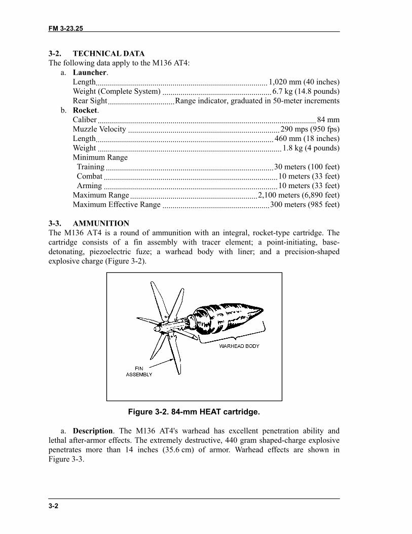
3-3. AMMUNITIONThe M136 AT4 is a round of ammunition with an integral, rocket-type cartridge. Thecartridge consists of a fin assembly with tracer element; a point-initiating, base-detonating, piezoelectric fuze; a warhead body with liner; and a precision-shapedexplosive charge (Figure 3-2).
Figure 3-2. 84-mm HEAT cartridge.
a. Description. The M136 AT4's warhead has excellent penetration ability andlethal after-armor effects. The extremely destructive, 440 gram shaped-charge explosivepenetrates more than 14 inches (35.6 cm) of armor. Warhead effects are shown inFigure 3-3.

FM 3-23.25
3-3
(1) Impact. The nose cone crushes; the impact sensor activates the fuze.(2) Ignition. The piezoelectric fuze element activates the electric detonator. The
booster detonates, initiating the main charge.(3) Penetration. The main charge fires and forces the warhead body liner into a
directional gas jet that penetrates armor plate.(4) After-Armor Effects (Spalling): The projectile fragments and incendiary effects
produce blinding light and destroy the interior of the target.
Figure 3-3. Effects of M136 AT4 warhead.
b. Packaging. Five M136 AT4s, each wrapped in a plastic barrier bag, are packedtogether in a wooden container. The containers are too heavy to stack more than fourdeep on the pallets (Figure 3-4).
Figure 3-4. Ammunition packaging and markings.
FM 3-23.25
3-4
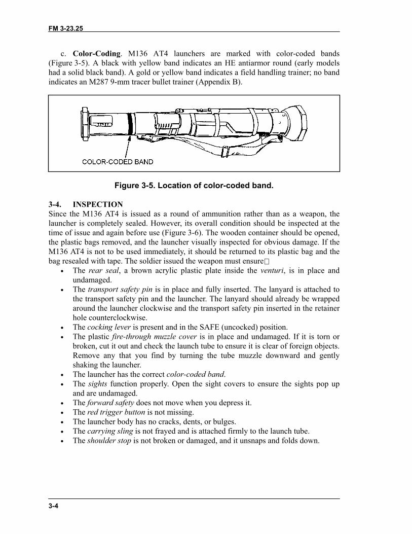
c. Color-Coding. M136 AT4 launchers are marked with color-coded bands(Figure 3-5). A black with yellow band indicates an HE antiarmor round (early modelshad a solid black band). A gold or yellow band indicates a field handling trainer; no bandindicates an M287 9-mm tracer bullet trainer (Appendix B).
Figure 3-5. Location of color-coded band.
3-4. INSPECTIONSince the M136 AT4 is issued as a round of ammunition rather than as a weapon, thelauncher is completely sealed. However, its overall condition should be inspected at thetime of issue and again before use (Figure 3-6). The wooden container should be opened,the plastic bags removed, and the launcher visually inspected for obvious damage. If theM136 AT4 is not to be used immediately, it should be returned to its plastic bag and thebag resealed with tape. The soldier issued the weapon must ensure
• The rear seal, a brown acrylic plastic plate inside the venturi, is in place andundamaged.
• The transport safety pin is in place and fully inserted. The lanyard is attached tothe transport safety pin and the launcher. The lanyard should already be wrappedaround the launcher clockwise and the transport safety pin inserted in the retainerhole counterclockwise.
• The cocking lever is present and in the SAFE (uncocked) position.• The plastic fire-through muzzle cover is in place and undamaged. If it is torn or
broken, cut it out and check the launch tube to ensure it is clear of foreign objects.Remove any that you find by turning the tube muzzle downward and gentlyshaking the launcher.
• The launcher has the correct color-coded band.• The sights function properly. Open the sight covers to ensure the sights pop up
and are undamaged.• The forward safety does not move when you depress it.• The red trigger button is not missing.• The launcher body has no cracks, dents, or bulges.• The carrying sling is not frayed and is attached firmly to the launch tube.• The shoulder stop is not broken or damaged, and it unsnaps and folds down.
FM 3-23.25
3-5
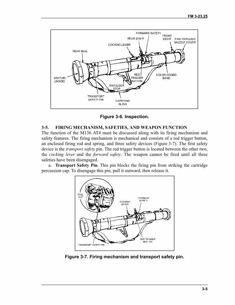
Figure 3-6. Inspection.
3-5. FIRING MECHANISM, SAFETIES, AND WEAPON FUNCTIONThe function of the M136 AT4 must be discussed along with its firing mechanism andsafety features. The firing mechanism is mechanical and consists of a red trigger button,an enclosed firing rod and spring, and three safety devices (Figure 3-7). The first safetydevice is the transport safety pin. The red trigger button is located between the other two,the cocking lever and the forward safety. The weapon cannot be fired until all threesafeties have been disengaged.
a. Transport Safety Pin. This pin blocks the firing pin from striking the cartridgepercussion cap. To disengage this pin, pull it outward, then release it.
Figure 3-7. Firing mechanism and transport safety pin.
FM 3-23.25
3-6
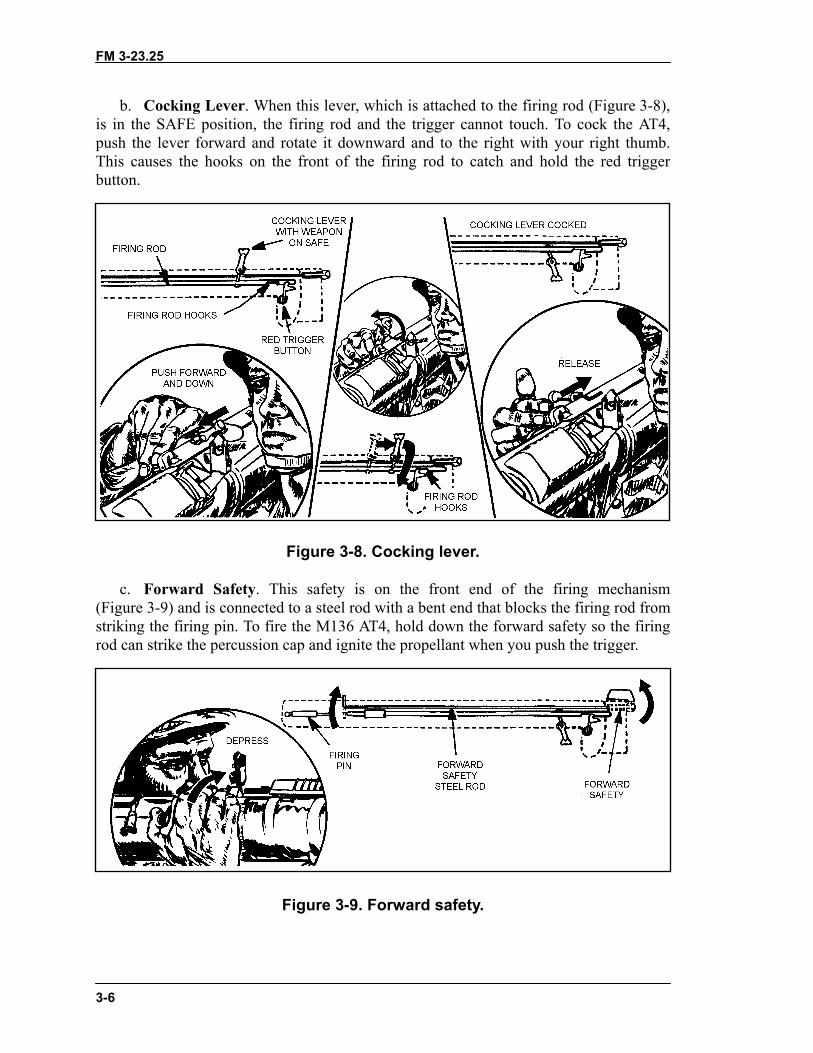
b. Cocking Lever. When this lever, which is attached to the firing rod (Figure 3-8),is in the SAFE position, the firing rod and the trigger cannot touch. To cock the AT4,push the lever forward and rotate it downward and to the right with your right thumb.This causes the hooks on the front of the firing rod to catch and hold the red triggerbutton.
Figure 3-8. Cocking lever.
c. Forward Safety. This safety is on the front end of the firing mechanism(Figure 3-9) and is connected to a steel rod with a bent end that blocks the firing rod fromstriking the firing pin. To fire the M136 AT4, hold down the forward safety so the firingrod can strike the percussion cap and ignite the propellant when you push the trigger.
Figure 3-9. Forward safety.
FM 3-23.25
3-7
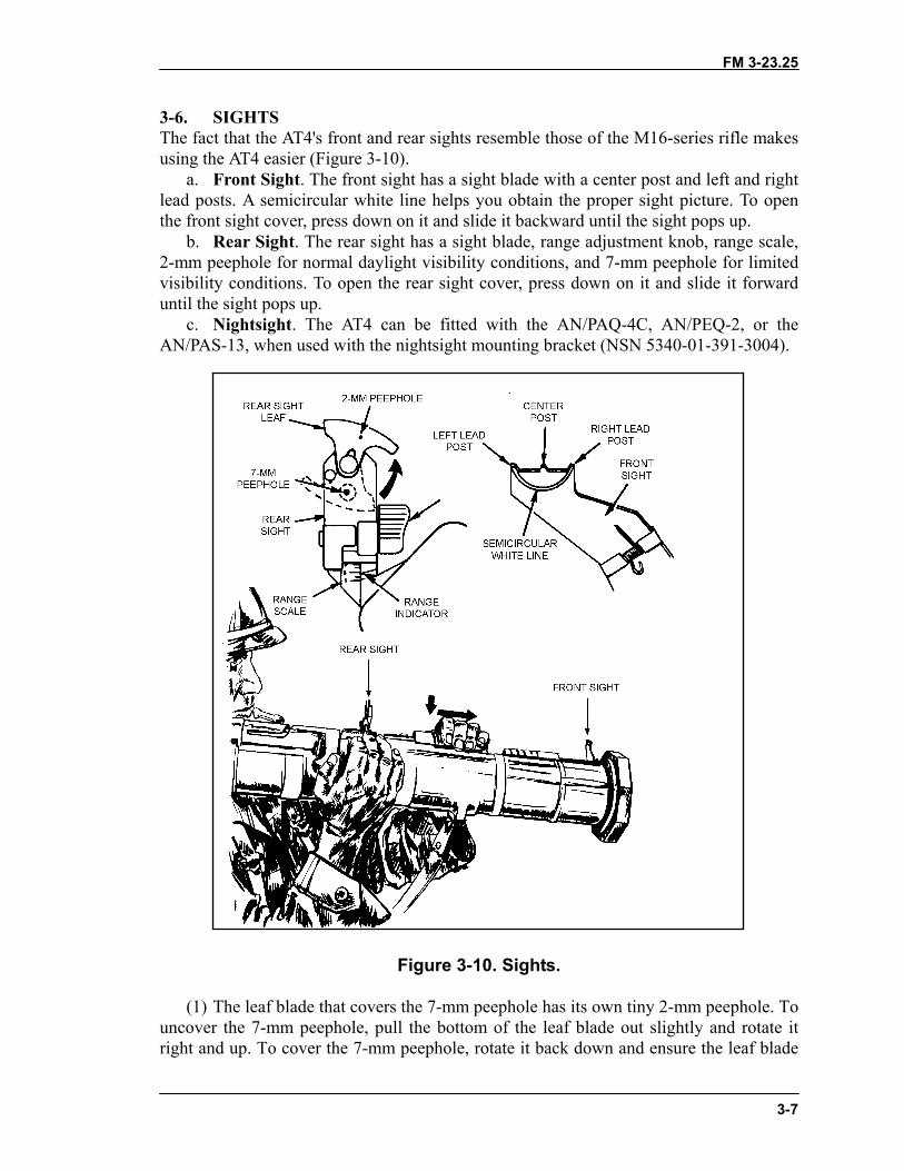
3-6. SIGHTSThe fact that the AT4's front and rear sights resemble those of the M16-series rifle makesusing the AT4 easier (Figure 3-10).
a. Front Sight. The front sight has a sight blade with a center post and left and rightlead posts. A semicircular white line helps you obtain the proper sight picture. To openthe front sight cover, press down on it and slide it backward until the sight pops up.
b. Rear Sight. The rear sight has a sight blade, range adjustment knob, range scale,2-mm peephole for normal daylight visibility conditions, and 7-mm peephole for limitedvisibility conditions. To open the rear sight cover, press down on it and slide it forwarduntil the sight pops up.
c. Nightsight. The AT4 can be fitted with the AN/PAQ-4C, AN/PEQ-2, or theAN/PAS-13, when used with the nightsight mounting bracket (NSN 5340-01-391-3004).
Figure 3-10. Sights.
(1) The leaf blade that covers the 7-mm peephole has its own tiny 2-mm peephole. Touncover the 7-mm peephole, pull the bottom of the leaf blade out slightly and rotate itright and up. To cover the 7-mm peephole, rotate it back down and ensure the leaf blade
FM 3-23.25
3-8
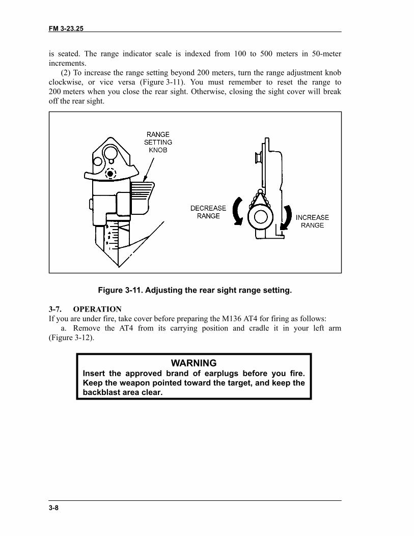
is seated. The range indicator scale is indexed from 100 to 500 meters in 50-meterincrements.
(2) To increase the range setting beyond 200 meters, turn the range adjustment knobclockwise, or vice versa (Figure 3-11). You must remember to reset the range to200 meters when you close the rear sight. Otherwise, closing the sight cover will breakoff the rear sight.
Figure 3-11. Adjusting the rear sight range setting.
3-7. OPERATIONIf you are under fire, take cover before preparing the M136 AT4 for firing as follows:
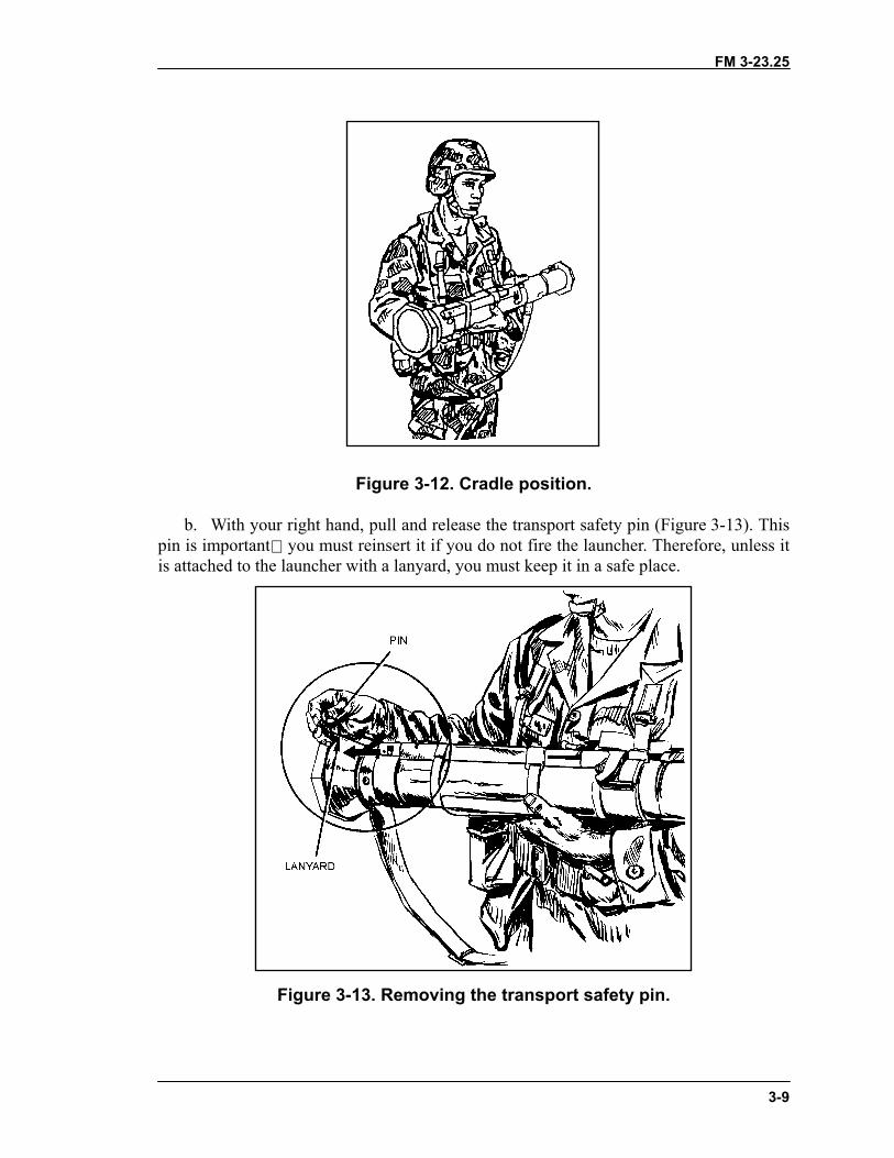
a. Remove the AT4 from its carrying position and cradle it in your left arm(Figure 3-12).
Insert the approved bKeep the weapon poinbackblast area clear.
WARNINGrand of earplugs before you fire.ted toward the target, and keep the
FM 3-23.25
3-9
Figure 3-12. Cradle position.
b. With your right hand, pull and release the transport safety pin (Figure 3-13). Thispin is important you must reinsert it if you do not fire the launcher. Therefore, unless itis attached to the launcher with a lanyard, you must keep it in a safe place.
Figure 3-13. Removing the transport safety pin.
FM 3-23.25
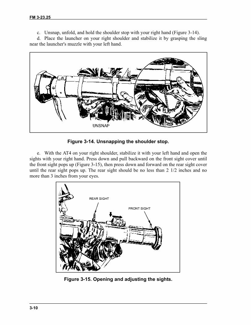
3-10
c. Unsnap, unfold, and hold the shoulder stop with your right hand (Figure 3-14).d. Place the launcher on your right shoulder and stabilize it by grasping the sling
near the launcher's muzzle with your left hand.
Figure 3-14. Unsnapping the shoulder stop.
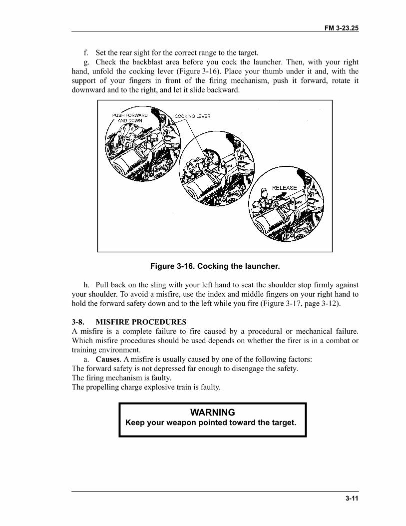
e. With the AT4 on your right shoulder, stabilize it with your left hand and open thesights with your right hand. Press down and pull backward on the front sight cover untilthe front sight pops up (Figure 3-15), then press down and forward on the rear sight coveruntil the rear sight pops up. The rear sight should be no less than 2 1/2 inches and nomore than 3 inches from your eyes.
Figure 3-15. Opening and adjusting the sights.
FM 3-23.25
3-11
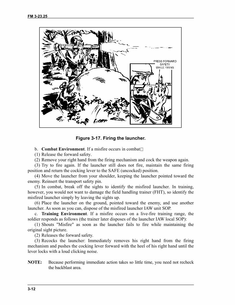
f. Set the rear sight for the correct range to the target.g. Check the backblast area before you cock the launcher. Then, with your right
hand, unfold the cocking lever (Figure 3-16). Place your thumb under it and, with thesupport of your fingers in front of the firing mechanism, push it forward, rotate itdownward and to the right, and let it slide backward.
Figure 3-16. Cocking the launcher.
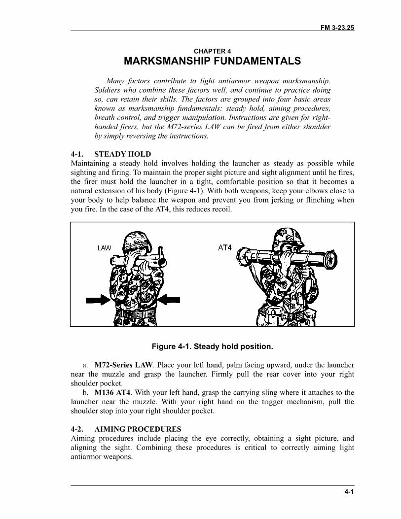
h. Pull back on the sling with your left hand to seat the shoulder stop firmly againstyour shoulder. To avoid a misfire, use the index and middle fingers on your right hand tohold the forward safety down and to the left while you fire (Figure 3-17, page 3-12).
3-8. MISFIRE PROCEDURESA misfire is a complete failure to fire caused by a procedural or mechanical failure.Which misfire procedures should be used depends on whether the firer is in a combat ortraining environment.
a. Causes. A misfire is usually caused by one of the following factors:The forward safety is not depressed far enough to disengage the safety.The firing mechanism is faulty.The propelling charge explosive train is faulty.
WARNINGKeep your weapon pointed toward the target.
FM 3-23.25
3-12
Figure 3-17. Firing the launcher.
b. Combat Environment. If a misfire occurs in combat(1) Release the forward safety.(2) Remove your right hand from the firing mechanism and cock the weapon again.(3) Try to fire again. If the launcher still does not fire, maintain the same firing
position and return the cocking lever to the SAFE (uncocked) position.(4) Move the launcher from your shoulder, keeping the launcher pointed toward the
enemy. Reinsert the transport safety pin.(5) In combat, break off the sights to identify the misfired launcher. In training,
however, you would not want to damage the field handling trainer (FHT), so identify themisfired launcher simply by leaving the sights up.
(6) Place the launcher on the ground, pointed toward the enemy, and use anotherlauncher. As soon as you can, dispose of the misfired launcher IAW unit SOP.
c. Training Environment. If a misfire occurs on a live-fire training range, thesoldier responds as follows (the trainer later disposes of the launcher IAW local SOP):
(1) Shouts "Misfire" as soon as the launcher fails to fire while maintaining theoriginal sight picture.
(2) Releases the forward safety.(3) Recocks the launcher: Immediately removes his right hand from the firing
mechanism and pushes the cocking lever forward with the heel of his right hand until thelever locks with a loud clicking noise.
NOTE: Because performing immediate action takes so little time, you need not recheckthe backblast area.

FM 3-23.25
3-13
(4) Press the forward safety all the way down and try to fire again. If the launcherstill fails to fire, shout misfire, release the forward safety, and move the cocking lever to theSAFE (uncocked) position. Move the launcher from your shoulder, keeping the weaponpointed toward the target and cradled in your left arm.
(5) Reinsert the transport safety pin, wait two minutes, then carefully lay thelauncher on the ground, muzzle toward the target.
NOTE: Notify the local ammunition supply and issue point of any unusual occurrence,regardless of whether the weapon fires or not. Examples include excessiveoverpressure, recoil, or heat on your face after you have fired the weapon (causedby the propellant burning after the round leaves the muzzle).
3-9. RESTORATION TO CARRYING CONFIGURATIONIf the launcher is prepared to fire, but then is not fired, it must be taken out of operationas follows:
a. Release the forward safety.b. Push forward and to the left on the cocking lever, and let it spring back into the
SAFE (uncocked) position.c. Move the launcher from your shoulder, ensuring the muzzle is pointed in the
direction of fire.d. With the launcher cradled in your left arm, replace the transport safety pin until it
is fully seated in the retainer hole.e. To avoid breaking off the rear sight, remember to reset the range indicator to the
200-meter setting before closing the rear sight cover.f. Lay down the sights and close their covers.g. Snap the shoulder stop into the closed position.h. Sling the launcher over your right shoulder and move to another location.
FM 3-23.25
4-1
CHAPTER 4MARKSMANSHIP FUNDAMENTALS
Many factors contribute to light antiarmor weapon marksmanship.Soldiers who combine these factors well, and continue to practice doingso, can retain their skills. The factors are grouped into four basic areasknown as marksmanship fundamentals: steady hold, aiming procedures,breath control, and trigger manipulation. Instructions are given for right-handed firers, but the M72-series LAW can be fired from either shoulderby simply reversing the instructions.
4-1. STEADY HOLDMaintaining a steady hold involves holding the launcher as steady as possible whilesighting and firing. To maintain the proper sight picture and sight alignment until he fires,the firer must hold the launcher in a tight, comfortable position so that it becomes anatural extension of his body (Figure 4-1). With both weapons, keep your elbows close toyour body to help balance the weapon and prevent you from jerking or flinching whenyou fire. In the case of the AT4, this reduces recoil.
Figure 4-1. Steady hold position.
a. M72-Series LAW. Place your left hand, palm facing upward, under the launchernear the muzzle and grasp the launcher. Firmly pull the rear cover into your rightshoulder pocket.
b. M136 AT4. With your left hand, grasp the carrying sling where it attaches to thelauncher near the muzzle. With your right hand on the trigger mechanism, pull theshoulder stop into your right shoulder pocket.
4-2. AIMING PROCEDURESAiming procedures include placing the eye correctly, obtaining a sight picture, andaligning the sight. Combining these procedures is critical to correctly aiming lightantiarmor weapons.
FM 3-23.25
4-2
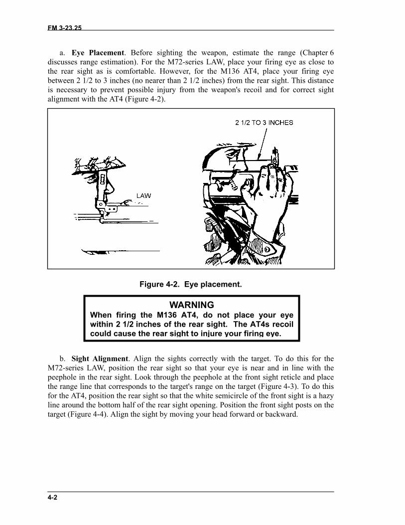
a. Eye Placement. Before sighting the weapon, estimate the range (Chapter 6discusses range estimation). For the M72-series LAW, place your firing eye as close tothe rear sight as is comfortable. However, for the M136 AT4, place your firing eyebetween 2 1/2 to 3 inches (no nearer than 2 1/2 inches) from the rear sight. This distanceis necessary to prevent possible injury from the weapon's recoil and for correct sightalignment with the AT4 (Figure 4-2).
Figure 4-2. Eye placement.
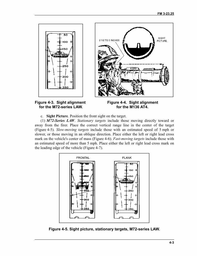
b. Sight Alignment. Align the M72-series LAW, position the rear peephole in the rear sight. Look throthe range line that corresponds to thefor the AT4, position the rear sight soline around the bottom half of the reatarget (Figure 4-4). Align the sight by
When firing the M1within 2 1/2 inches ocould cause the rear
WARNING36 AT4, do not place your eyef the rear sight. The AT4s recoil sight to injure your firing eye.
sights correctly with the target. To do this for thesight so that your eye is near and in line with theugh the peephole at the front sight reticle and place target's range on the target (Figure 4-3). To do this that the white semicircle of the front sight is a hazyr sight opening. Position the front sight posts on the moving your head forward or backward.
FM 3-23.25
4-3
Figure 4-3. Sight alignment Figure 4-4. Sight alignment for the M72-series LAW. for the M136 AT4.
c. Sight Picture. Position the front sight on the target.(1) M72-Series LAW. Stationary targets include those moving directly toward or
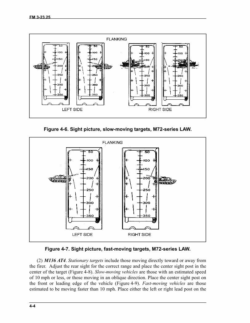
away from the firer. Place the correct vertical range line in the center of the target(Figure 4-5). Slow-moving targets include those with an estimated speed of 5 mph orslower, or those moving in an oblique direction. Place either the left or right lead crossmark on the vehicle's center of mass (Figure 4-6). Fast-moving targets include those withan estimated speed of more than 5 mph. Place either the left or right lead cross mark onthe leading edge of the vehicle (Figure 4-7).
Figure 4-5. Sight picture, stationary targets, M72-series LAW.
FM 3-23.25
4-4
Figure 4-6. Sight picture, slow-moving targets, M72-series LAW.
Figure 4-7. Sight picture, fast-moving targets, M72-series LAW.
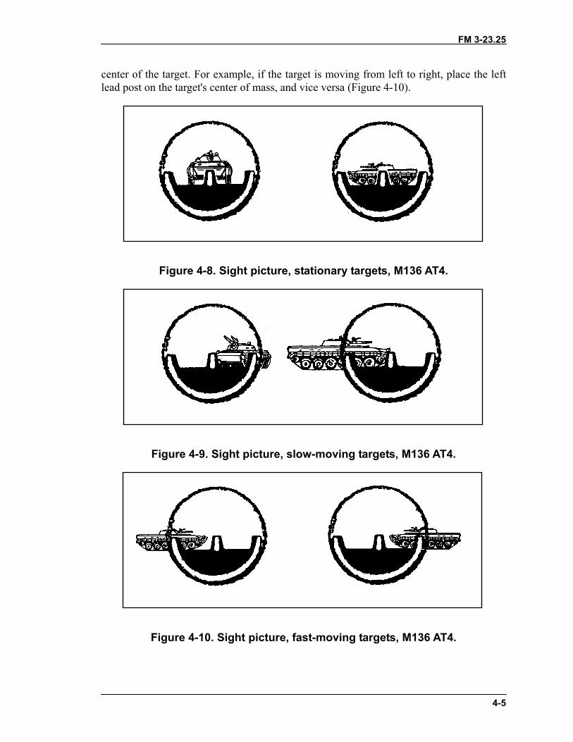
(2) M136 AT4. Stationary targets include those moving directly toward or away fromthe firer. Adjust the rear sight for the correct range and place the center sight post in thecenter of the target (Figure 4-8). Slow-moving vehicles are those with an estimated speedof 10 mph or less, or those moving in an oblique direction. Place the center sight post onthe front or leading edge of the vehicle (Figure 4-9). Fast-moving vehicles are thoseestimated to be moving faster than 10 mph. Place either the left or right lead post on the
FM 3-23.25
4-5
center of the target. For example, if the target is moving from left to right, place the leftlead post on the target's center of mass, and vice versa (Figure 4-10).
Figure 4-8. Sight picture, stationary targets, M136 AT4.
Figure 4-9. Sight picture, slow-moving targets, M136 AT4.
Figure 4-10. Sight picture, fast-moving targets, M136 AT4.
FM 3-23.25
4-6
4-3. BREATH CONTROLBreath control is as important when firing a light antiarmor weapon as it is when firing anindividual weapon. Breathing while firing can cause a miss. To control breathing, thefirer breathes deeply a couple of times, takes one last deep breath, exhales partly, holdshis breath, sights, and fires.
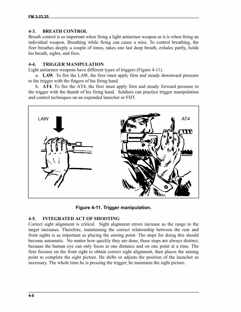
4-4. TRIGGER MANIPULATIONLight antiarmor weapons have different types of triggers (Figure 4-11).
a. LAW. To fire the LAW, the firer must apply firm and steady downward pressureto the trigger with the fingers of his firing hand.
b. AT4. To fire the AT4, the firer must apply firm and steady forward pressure tothe trigger with the thumb of his firing hand. Soldiers can practice trigger manipulationand control techniques on an expended launcher or FHT.
Figure 4-11. Trigger manipulation.
4-5. INTEGRATED ACT OF SHOOTINGCorrect sight alignment is critical. Sight alignment errors increase as the range to thetarget increases. Therefore, maintaining the correct relationship between the rear andfront sights is as important as placing the aiming point. The steps for doing this shouldbecome automatic. No matter how quickly they are done, these steps are always distinct,because the human eye can only focus at one distance and on one point at a time. Thefirer focuses on the front sight to obtain correct sight alignment, then places the aimingpoint to complete the sight picture. He shifts or adjusts the position of the launcher asnecessary. The whole time he is pressing the trigger, he maintains the sight picture.
FM 3-23.25
5-1
CHAPTER 5FIRING POSITIONS
This chapter explains the basic firing positions used with lightantiarmor weapons. Instructions for each are given for right-handedfirers, but the M72-series LAW can be fired from either shoulder by simplyreversing the instructions. Though each weapon can be fired from all fourof the basic firing positions, individual physique determines exact bodyand hand positions. Firing from a supported position naturally increasesaccuracy, which improves the odds for a first-round hit or kill. Basicsafety considerations are the same for all light antiarmor weapons, butadditional considerations for each firing position are provided here.
5-1. STANDING POSITIONTwo standing positions are used: a basic standing position and one modified for theinfantry fighting position.
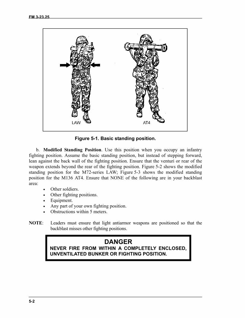
a. Basic Standing Position. Raise the launcher slightly higher than shoulder level.Execute a left face, rotate your shoulder under the launcher, and spread your feet acomfortable distance apart. Move your left foot 15 to 24 inches forward, keeping yourhips level and your weight balanced on both feet. To obtain a firm, stable position, tuckboth elbows tightly into your body. To track a moving target, turn your body at thewaist―not with your legs. This enables you to track the target smoothly. Unless you arebehind a protective barrier such as a wall, the standing position exposes you more thanany other position to enemy observation and possible suppression. Differences betweenweapons with respect to the standing position are as follows (Figure 5-1, page 5-2):
(1) M72-Series LAW. Place your nonfiring hand about 4 inches from the front of themuzzle, with your firing hand on the rear cover. After placing the weapon on yourshoulder, release the rear cover and place your firing hand on the trigger. Cup thelauncher in the palm of your nonfiring hand. Position your firing eye as close to the rearsight as is comfortable.
(2) M136 AT4. Grasp the sling near the launcher with your left hand and the shoulderstop with your right hand. Raise the launcher above shoulder level. After placing thelauncher on your shoulder, release the shoulder stop and place your right hand on thetrigger. Place your firing eye 2 1/2 to 3 inches from the rear sight.
WARNINGAlways keep the launcher pointed in the direction of fire.
FM 3-23.25
5-2
Figure 5-1. Basic standing position.
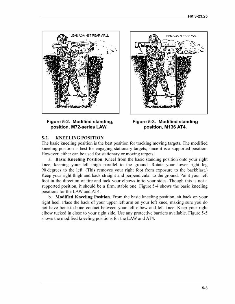
b. Modified Standing Position. Use this position when you occupy an infantryfighting position. Assume the basic standing position, but instead of stepping forward,lean against the back wall of the fighting position. Ensure that the venturi or rear of theweapon extends beyond the rear of the fighting position. Figure 5-2 shows the modifiedstanding position for the M72-series LAW; Figure 5-3 shows the modified standingposition for the M136 AT4. Ensure that NONE of the following are in your backblastarea:
• Other soldiers.• Other fighting positions.• Equipment.• Any part of your own fighting position.• Obstructions within 5 meters.
NOTE: Leaders must ensure that light antiarmor weapons are positioned so that thebackblast misses other fighting positions.
DANGERNEVER FIRE FROM WITHIN A COMPLETELY ENCLOSED,UNVENTILATED BUNKER OR FIGHTING POSITION.
FM 3-23.25
5-3
Figure 5-2. Modified standing, Figure 5-3. Modified standing position, M72-series LAW. position, M136 AT4.
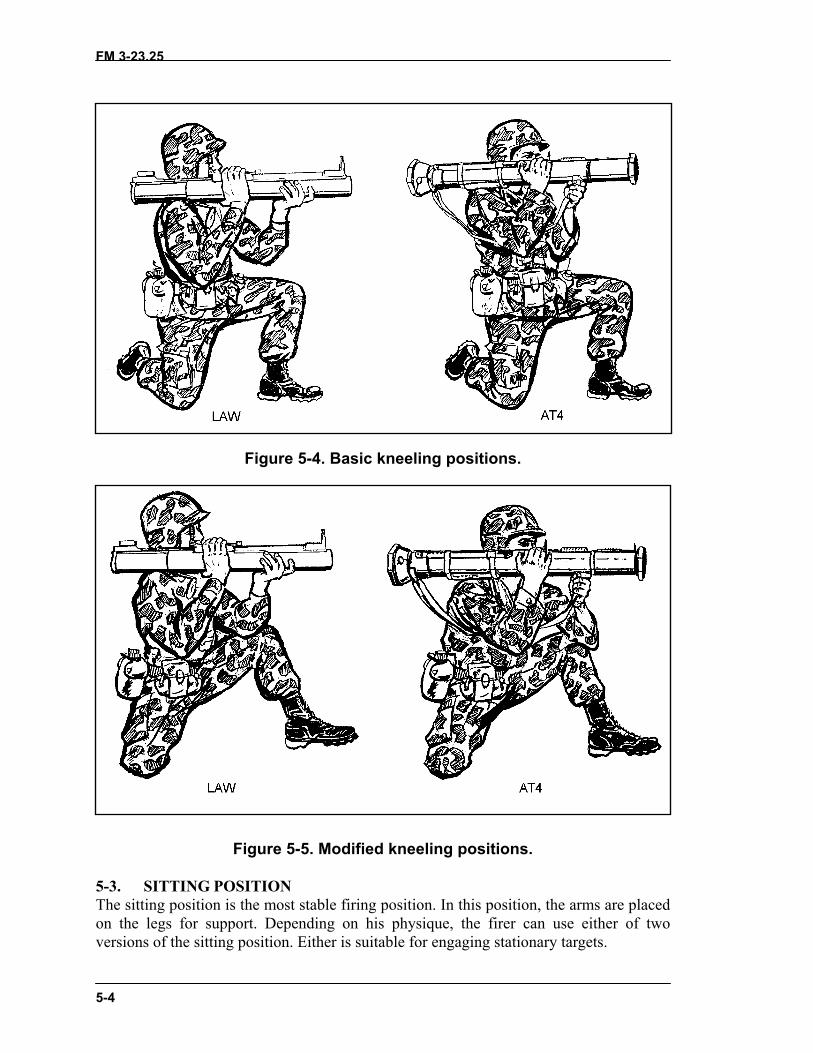
5-2. KNEELING POSITIONThe basic kneeling position is the best position for tracking moving targets. The modifiedkneeling position is best for engaging stationary targets, since it is a supported position.However, either can be used for stationary or moving targets.
a. Basic Kneeling Position. Kneel from the basic standing position onto your rightknee, keeping your left thigh parallel to the ground. Rotate your lower right leg90 degrees to the left. (This removes your right foot from exposure to the backblast.)Keep your right thigh and back straight and perpendicular to the ground. Point your leftfoot in the direction of fire and tuck your elbows in to your sides. Though this is not asupported position, it should be a firm, stable one. Figure 5-4 shows the basic kneelingpositions for the LAW and AT4.
b. Modified Kneeling Position. From the basic kneeling position, sit back on yourright heel. Place the back of your upper left arm on your left knee, making sure you donot have bone-to-bone contact between your left elbow and left knee. Keep your rightelbow tucked in close to your right side. Use any protective barriers available. Figure 5-5shows the modified kneeling positions for the LAW and AT4.
FM 3-23.25
5-4
Figure 5-4. Basic kneeling positions.
Figure 5-5. Modified kneeling positions.
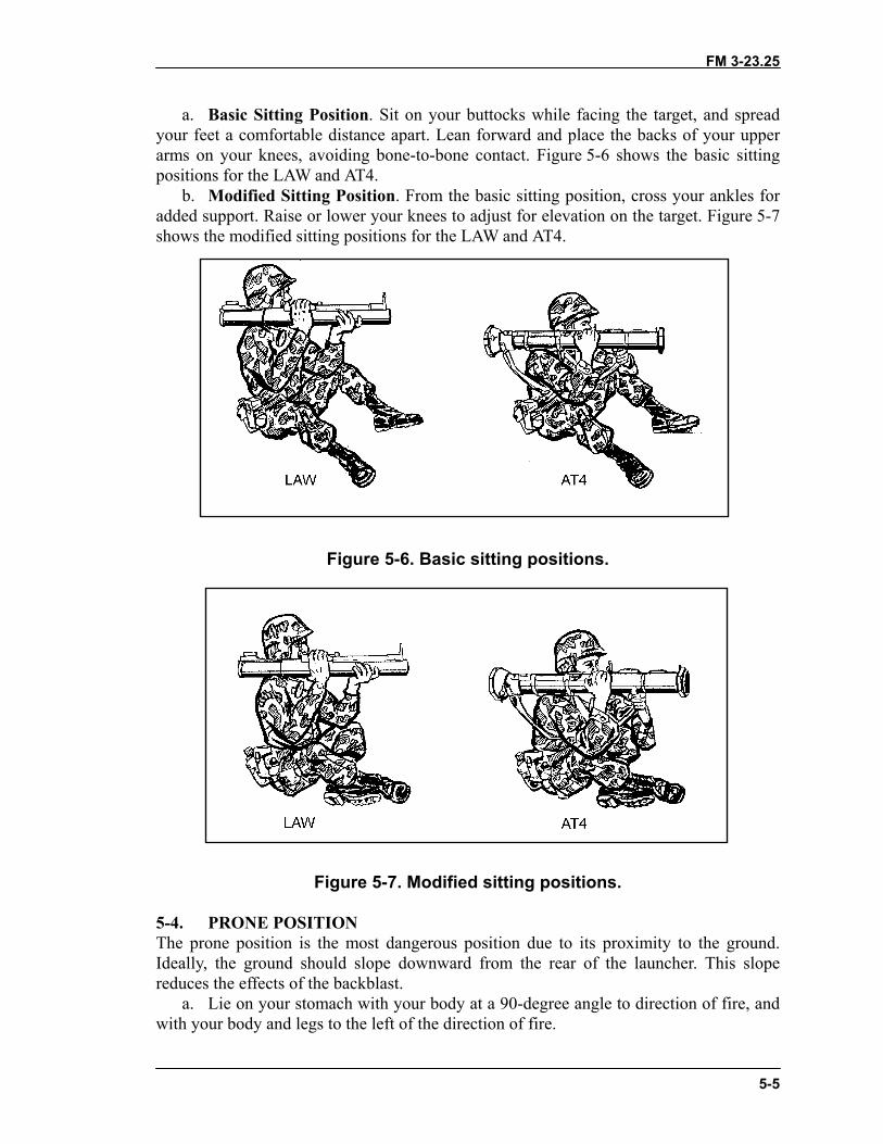
5-3. SITTING POSITIONThe sitting position is the most stable firing position. In this position, the arms are placedon the legs for support. Depending on his physique, the firer can use either of twoversions of the sitting position. Either is suitable for engaging stationary targets.
FM 3-23.25
5-5
a. Basic Sitting Position. Sit on your buttocks while facing the target, and spreadyour feet a comfortable distance apart. Lean forward and place the backs of your upperarms on your knees, avoiding bone-to-bone contact. Figure 5-6 shows the basic sittingpositions for the LAW and AT4.
b. Modified Sitting Position. From the basic sitting position, cross your ankles foradded support. Raise or lower your knees to adjust for elevation on the target. Figure 5-7shows the modified sitting positions for the LAW and AT4.
Figure 5-6. Basic sitting positions.
Figure 5-7. Modified sitting positions.
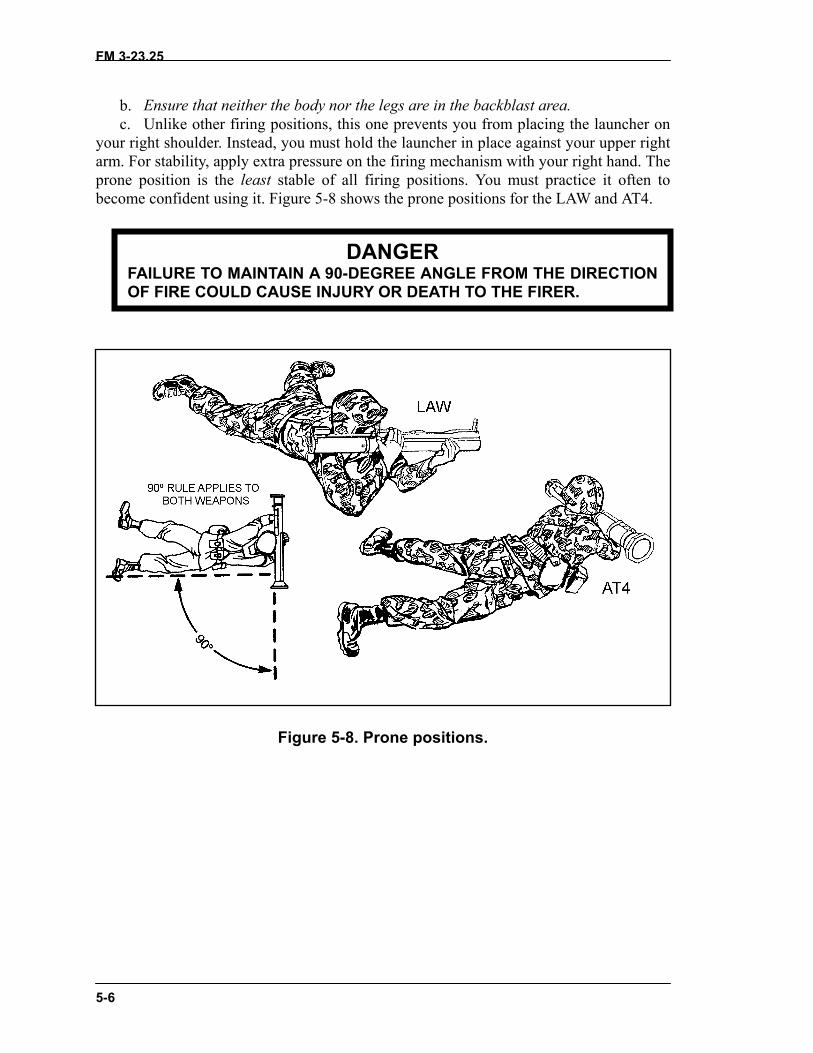
5-4. PRONE POSITIONThe prone position is the most dangerous position due to its proximity to the ground.Ideally, the ground should slope downward from the rear of the launcher. This slopereduces the effects of the backblast.
a. Lie on your stomach with your body at a 90-degree angle to direction of fire, andwith your body and legs to the left of the direction of fire.
FM 3-23.25
5-6
b. Ensure that neither the body nor the legs are in the backblast area.c. Unlike other firing positions, this one prevents you from placing the launcher on
your right shoulder. Instead, you must hold the launcher in place against your upper rightarm. For stability, apply extra pressure on the firing mechanism with your right hand. Theprone position is the least stable of all firing positions. You must practice it often tobecome confident using it. Figure 5-8 shows the prone positions for the LAW and AT4.
Figure 5
FAILURE TO MAINTAIN A 90OF FIRE COULD CAUSE INJ
DANGER-DEGREE ANGLE FROM THE DIRECTIONURY OR DEATH TO THE FIRER.
-8. Prone positions.
FM 3-23.25
6-1
CHAPTER 6COMBAT TECHNIQUES
This chapter discusses employment techniques for light antiarmorweapons, all of which require at least basic gunnery skills. Techniquesthat require advanced skills are identified as such.
6-1. RANGE ESTIMATIONA firer who can accurately estimate the range to the target has a better chance of hittingit, regardless of the weapon used. Common methods of estimating range are listed belowfrom the most to the least accurate. The tactical situation determines the method to beused:
a. Using range finders.b. Measuring the distance on a map after correctly plotting your own position.c. Pacing. Remember your individual pace count.d. Using pair and sequence methods of target engagement. This method should be
used only when in contact with the enemy.e. Estimating range visually. This is the least accurate method of estimating range
and therefore the least desirable. However, in an offensive operation or hasty defense, itmay be the only method available to the light antiarmor firer. Thus, soldiers mustcontinually train to improve their skill at visual estimation (STP 21-1-SMCT). Leadersshould identify, coordinate, and record ranges to possible armored vehicle engagementlocations on squad and platoon sector sketches.
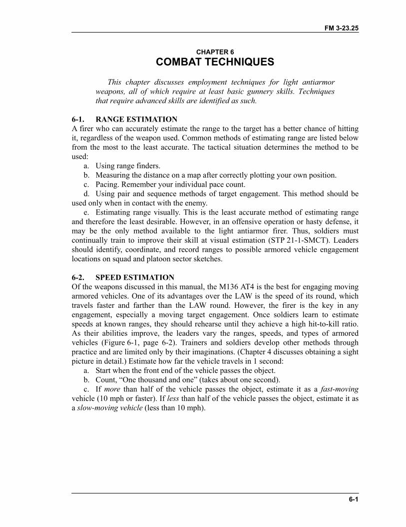
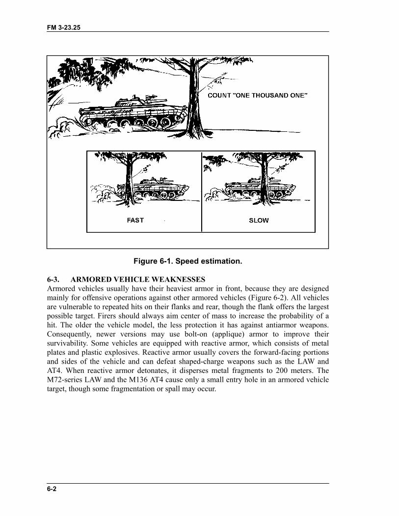
6-2. SPEED ESTIMATIONOf the weapons discussed in this manual, the M136 AT4 is the best for engaging movingarmored vehicles. One of its advantages over the LAW is the speed of its round, whichtravels faster and farther than the LAW round. However, the firer is the key in anyengagement, especially a moving target engagement. Once soldiers learn to estimatespeeds at known ranges, they should rehearse until they achieve a high hit-to-kill ratio.As their abilities improve, the leaders vary the ranges, speeds, and types of armoredvehicles (Figure 6-1, page 6-2). Trainers and soldiers develop other methods throughpractice and are limited only by their imaginations. (Chapter 4 discusses obtaining a sightpicture in detail.) Estimate how far the vehicle travels in 1 second:
a. Start when the front end of the vehicle passes the object.b. Count, “One thousand and one” (takes about one second).c. If more than half of the vehicle passes the object, estimate it as a fast-moving
vehicle (10 mph or faster). If less than half of the vehicle passes the object, estimate it asa slow-moving vehicle (less than 10 mph).
FM 3-23.25
6-2
Figure 6-1. Speed estimation.
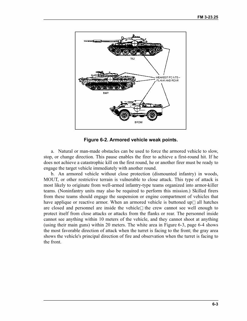
6-3. ARMORED VEHICLE WEAKNESSESArmored vehicles usually have their heaviest armor in front, because they are designedmainly for offensive operations against other armored vehicles (Figure 6-2). All vehiclesare vulnerable to repeated hits on their flanks and rear, though the flank offers the largestpossible target. Firers should always aim center of mass to increase the probability of ahit. The older the vehicle model, the less protection it has against antiarmor weapons.Consequently, newer versions may use bolt-on (applique) armor to improve theirsurvivability. Some vehicles are equipped with reactive armor, which consists of metalplates and plastic explosives. Reactive armor usually covers the forward-facing portionsand sides of the vehicle and can defeat shaped-charge weapons such as the LAW andAT4. When reactive armor detonates, it disperses metal fragments to 200 meters. TheM72-series LAW and the M136 AT4 cause only a small entry hole in an armored vehicletarget, though some fragmentation or spall may occur.
FM 3-23.25
6-3
Figure 6-2. Armored vehicle weak points.
a. Natural or man-made obstacles can be used to force the armored vehicle to slow,stop, or change direction. This pause enables the firer to achieve a first-round hit. If hedoes not achieve a catastrophic kill on the first round, he or another firer must be ready toengage the target vehicle immediately with another round.
b. An armored vehicle without close protection (dismounted infantry) in woods,MOUT, or other restrictive terrain is vulnerable to close attack. This type of attack ismost likely to originate from well-armed infantry-type teams organized into armor-killerteams. (Noninfantry units may also be required to perform this mission.) Skilled firersfrom these teams should engage the suspension or engine compartment of vehicles thathave applique or reactive armor. When an armored vehicle is buttoned up all hatchesare closed and personnel are inside the vehicle the crew cannot see well enough toprotect itself from close attacks or attacks from the flanks or rear. The personnel insidecannot see anything within 10 meters of the vehicle, and they cannot shoot at anything(using their main guns) within 20 meters. The white area in Figure 6-3, page 6-4 showsthe most favorable direction of attack when the turret is facing to the front; the gray areashows the vehicle's principal direction of fire and observation when the turret is facing tothe front.

FM 3-23.25
6-4
c. Armored vehicle kills are classified according to the level of damage achieved(Table 6-1).
Figure 6-3. Limited visibility of armored vehicles.
TYPE OF KILLPART OF VEHICLE
DAMAGED OR DESTROYED CAPABILITY AFTER KILLMobility Kill Suspension (track, wheels, or road
wheels) or power train (engine ortransmission) has been damaged.
Vehicle cannot move, but it canstill return fire.
Firepower Kill Main armament has been disabled. Vehicle can still move, so it canget away.
Catastrophic Kill Ammunition or fuel storage sectionhas been hit by more than one round.
Vehicle completely destroyed.
Table 6-1. Armored vehicle kills.
6-4. METHODS OF ENGAGEMENTThe four engagement methods include single, sequence, pair, and volley firing. Theleader evaluates the situation on the ground to determine which of these methods to use.Regardless of whether they are used singly or in combination, communications areneeded as well. The methods of engagement are rehearsed IAW unit SOP.
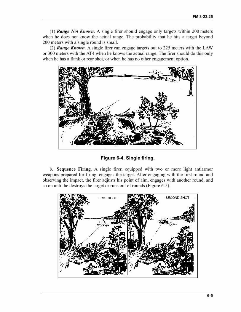
a. Single Firing. A single soldier with one light antiarmor weapon may engage anarmored vehicle, but this is not the preferred method of engagement. Several lightantiarmor weapons are required to kill an armored vehicle. A single firer firing one roundmust hit a vital part of the target to damage it at all (Figure 6-4).
FM 3-23.25
6-5
(1) Range Not Known. A single firer should engage only targets within 200 meterswhen he does not know the actual range. The probability that he hits a target beyond200 meters with a single round is small.
(2) Range Known. A single firer can engage targets out to 225 meters with the LAWor 300 meters with the AT4 when he knows the actual range. The firer should do this onlywhen he has a flank or rear shot, or when he has no other engagement option.
Figure 6-4. Single firing.
b. Sequence Firing. A single firer, equipped with two or more light antiarmorweapons prepared for firing, engages the target. After engaging with the first round andobserving the impact, the firer adjusts his point of aim, engages with another round, andso on until he destroys the target or runs out of rounds (Figure 6-5).
FM 3-23.25
6-6
Figure 6-5. Sequence firing.
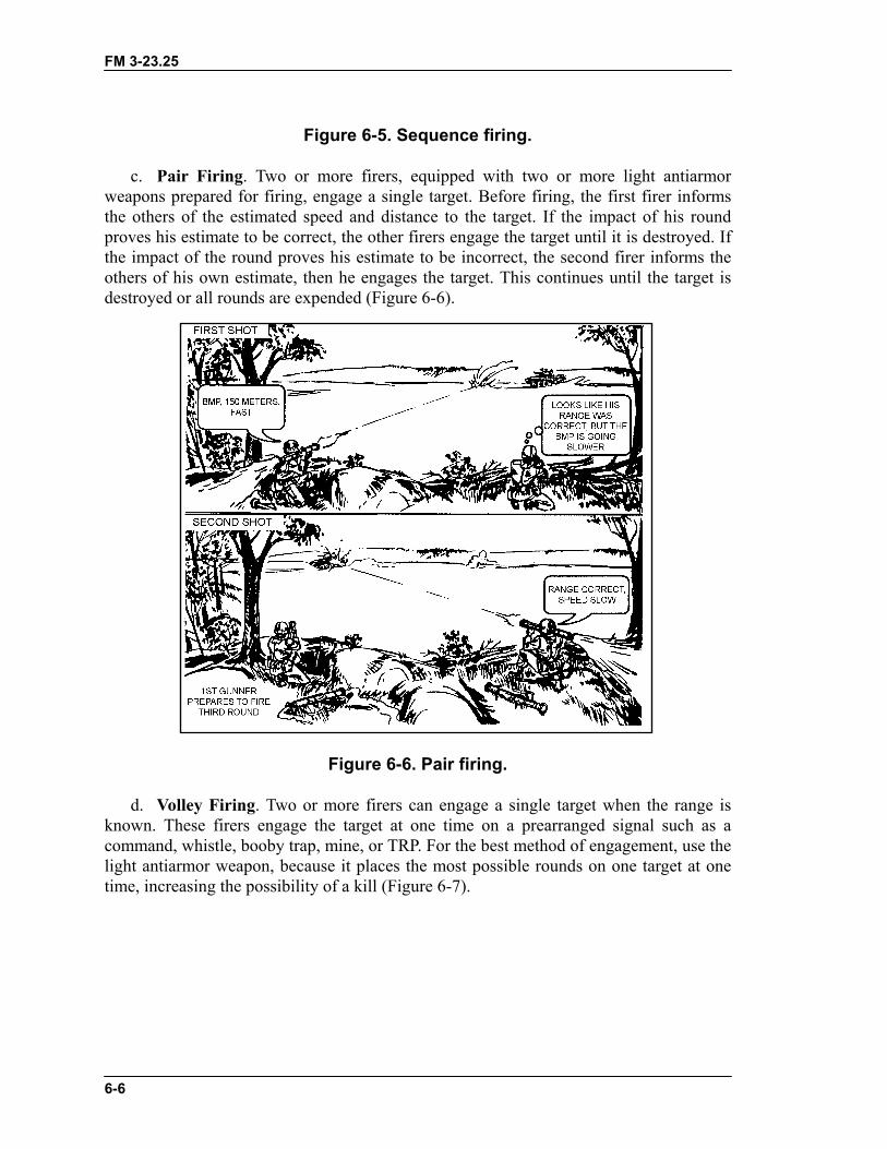
c. Pair Firing. Two or more firers, equipped with two or more light antiarmorweapons prepared for firing, engage a single target. Before firing, the first firer informsthe others of the estimated speed and distance to the target. If the impact of his roundproves his estimate to be correct, the other firers engage the target until it is destroyed. Ifthe impact of the round proves his estimate to be incorrect, the second firer informs theothers of his own estimate, then he engages the target. This continues until the target isdestroyed or all rounds are expended (Figure 6-6).
Figure 6-6. Pair firing.
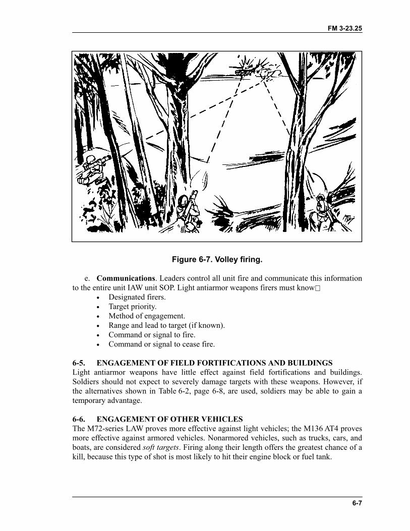
d. Volley Firing. Two or more firers can engage a single target when the range isknown. These firers engage the target at one time on a prearranged signal such as acommand, whistle, booby trap, mine, or TRP. For the best method of engagement, use thelight antiarmor weapon, because it places the most possible rounds on one target at onetime, increasing the possibility of a kill (Figure 6-7).
FM 3-23.25
6-7
Figure 6-7. Volley firing.
e. Communications. Leaders control all unit fire and communicate this informationto the entire unit IAW unit SOP. Light antiarmor weapons firers must know
• Designated firers.• Target priority.• Method of engagement.• Range and lead to target (if known).• Command or signal to fire.• Command or signal to cease fire.
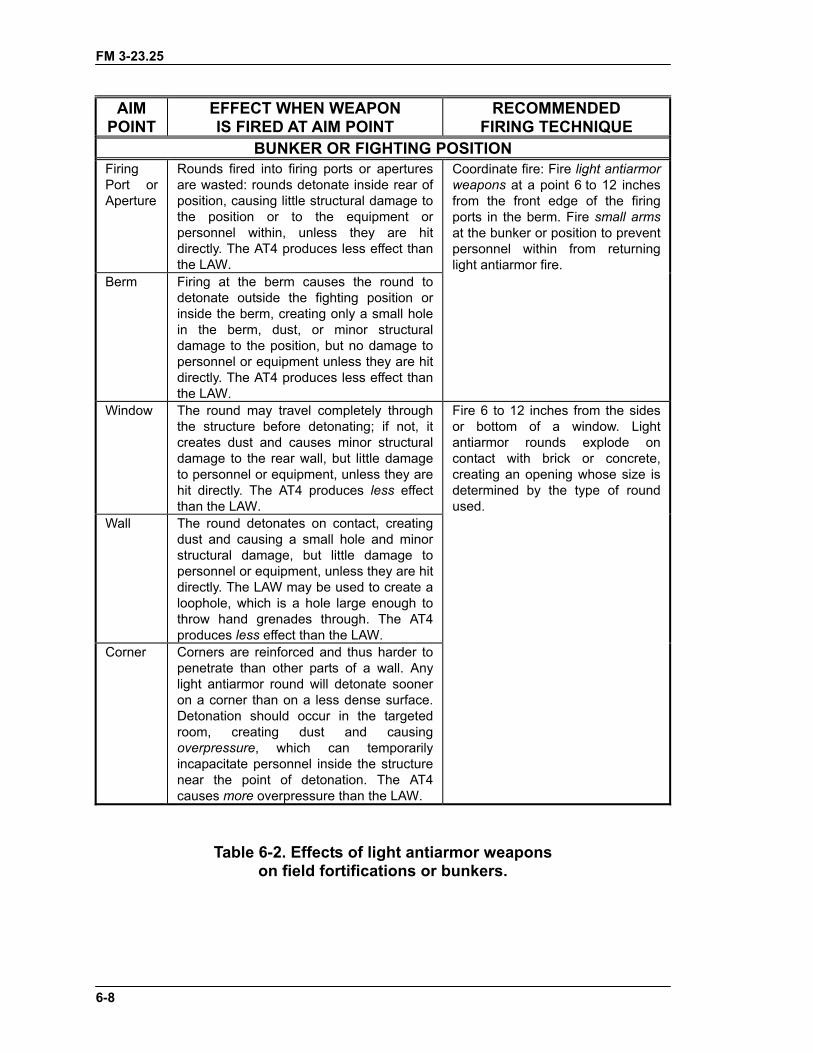
6-5. ENGAGEMENT OF FIELD FORTIFICATIONS AND BUILDINGSLight antiarmor weapons have little effect against field fortifications and buildings.Soldiers should not expect to severely damage targets with these weapons. However, ifthe alternatives shown in Table 6-2, page 6-8, are used, soldiers may be able to gain atemporary advantage.
6-6. ENGAGEMENT OF OTHER VEHICLESThe M72-series LAW proves more effective against light vehicles; the M136 AT4 provesmore effective against armored vehicles. Nonarmored vehicles, such as trucks, cars, andboats, are considered soft targets. Firing along their length offers the greatest chance of akill, because this type of shot is most likely to hit their engine block or fuel tank.
FM 3-23.25
6-8
AIMPOINT
EFFECT WHEN WEAPONIS FIRED AT AIM POINT
RECOMMENDEDFIRING TECHNIQUE
BUNKER OR FIGHTING POSITIONFiringPort orAperture
Rounds fired into firing ports or aperturesare wasted: rounds detonate inside rear ofposition, causing little structural damage tothe position or to the equipment orpersonnel within, unless they are hitdirectly. The AT4 produces less effect thanthe LAW.
Coordinate fire: Fire light antiarmorweapons at a point 6 to 12 inchesfrom the front edge of the firingports in the berm. Fire small armsat the bunker or position to preventpersonnel within from returninglight antiarmor fire.
Berm Firing at the berm causes the round todetonate outside the fighting position orinside the berm, creating only a small holein the berm, dust, or minor structuraldamage to the position, but no damage topersonnel or equipment unless they are hitdirectly. The AT4 produces less effect thanthe LAW.
Window The round may travel completely throughthe structure before detonating; if not, itcreates dust and causes minor structuraldamage to the rear wall, but little damageto personnel or equipment, unless they arehit directly. The AT4 produces less effectthan the LAW.
Fire 6 to 12 inches from the sidesor bottom of a window. Lightantiarmor rounds explode oncontact with brick or concrete,creating an opening whose size isdetermined by the type of roundused.
Wall The round detonates on contact, creatingdust and causing a small hole and minorstructural damage, but little damage topersonnel or equipment, unless they are hitdirectly. The LAW may be used to create aloophole, which is a hole large enough tothrow hand grenades through. The AT4produces less effect than the LAW.
Corner Corners are reinforced and thus harder topenetrate than other parts of a wall. Anylight antiarmor round will detonate sooneron a corner than on a less dense surface.Detonation should occur in the targetedroom, creating dust and causingoverpressure, which can temporarilyincapacitate personnel inside the structurenear the point of detonation. The AT4causes more overpressure than the LAW.
Table 6-2. Effects of light antiarmor weaponson field fortifications or bunkers.

FM 3-23.25
6-7. LIMITED VISIBILITY ENGAGEMENTSLimited visibility engagements can be conducted using various night vision devices orwith artificial illumination. However, when NVDs or artificial illumination is used,limited visibility can reduce the maximum effective range for light antiarmor weapons byat least one-third. To avoid fratricide, leaders must ensure all designated light antiarmorweapon firers are trained to use their weapons in limited visibility.
a. Night Vision Device. Before a NVD can be used with the M136/AT4, it must beremoved from its designated weapon (M249 machine gun or automatic weapon, or M60machine gun) and the M136/AT4 mounting bracket must be attached. Appendix Fdescribes the various NVDs that can be used, it also gives information for mounting,boresighting, and zeroing procedures for each NVD.
b. Artificial Illumination. If artificial illumination is used during a limited visibilityengagement, it should be placed above and slightly beyond the target. However, theability to identify and engage targets is even less with artificial illumination than withNVDs.
6-8. ENGAGEMENT IN NBC CONDITIONSWearing a protective mask limits the firer's ability to sight the weapon. Wearing NBCgloves limits his ability to manipulate the firing mechanism.
a. Sighting the Weapon. Sighting while wearing the protective mask may requirerotating the weapon slightly counterclockwise. The mask also makes determining thelocation, identity, and engageability of targets more difficult.
b. Firing the Weapon. Practice manipulating the firing mechanism while wearingNBC gloves.
NOTE: When live firing either a light antiarmor weapon or its subcaliber trainer, aimwithin range firing limits.
6-9. ENGAGEMENT FROM ANFiring from an enclosure creates uniqenclosures (in combat only), leaders in combat, when no other tactical openclosure. If it must be employed minimum requirements. The M72-seenclosure but, again, only whenrequirements:
THE M136 AT4 IS NNEVER FIRE IT FROMSO ONLY WHEN NOTHE OVERPRESSURECONDITIONS THAT CYOU, THEY CAN INJUYOU TEMPORARILY O
DANGEROT RATED SAFE. IN TRAINING, AN ENCLOSURE; IN COMBAT, DO
OTHER POSITION IS AVAILABLE. AND BLAST COMBINED CREATE
AN KILL YOU. IF THEY DON'T KILLRE YOU SERIOUSLY OR DEAFENR PERMANENTLY
6-9
ENCLOSUREue hazards. As such, before positioning soldiers in
must consider several factors that affect safety. Onlytion exists, should the M136 AT4 be fired from anthis way, the enclosure must meet the followingries LAW has been rated as safe for use from an
the enclosure meets the following minimum
FM 3-23.25
6-10
a. Construction. The building must be sturdily constructed to reduce the structuraldamage that would occur in a weakly constructed enclosure such as one made of wood orstucco.
b. Size of Enclosure. Minimum measurements for the enclosure are as follows:• AT4 minimum room size 17 x 24 feet.• LAW minimum room size 12 x 15 feet.• Both minimum ceiling height 8 feet.
c. Ventilation to the Rear and Sides. To allow for the backblast, at least20 square feet of ventilation such as a standard 3-foot by 7-foot doorway must beprovided directly behind the firer. More doors and windows are removed beside andbehind the position to increase ventilation and reduce overpressure, noise, and blasteffects. Without sufficient ventilation, the blast would weaken or collapse the walls. Onthe front wall, windows and doors are reinforced rather than removed, because removingwould draw attention to the position. Reinforcing the windows also helps protect the firerfrom enemy direct-fire weapons.
d. Objects and Debris. All objects and debris are removed from the rear of theweapon, because the backblast causes them to fly around the room injuring personnel.
e. Muzzle Clearance. Muzzle Clearance must be at least 6 inches.f. Weapon Clearance. Properly positioning the weapons within the enclosure is
vital to the safety and survival of all personnel in the enclosure. The weapons should bepositioned so that no walls are within 5 meters to the rear or side of the weapon.
g. Personnel Positions. If any other soldiers must be present, then they must remainforward of the rear of the launcher and avoid standing in corners or near walls. Ifpossible, they should construct reinforced positions that fit the previous criteria and thatcan protect them in case the building collapses.
6-10. ENGAGEMENT BEYOND MAXIMUM EFFECTIVE RANGE(M136 AT4 ONLY)A skilled M136 AT4 firer can engage targets beyond the weapon's maximum effectiverange of 300 meters, up to 550 meters. Beyond 550 meters, the firer must aim higher thancenter of mass and apply additional lead for moving targets. Commanders must realizethat accuracy is reduced at these ranges. Also, firing at these ranges identifies the firingposition to the enemy.
6-11. OFFENSIVE OPERATIONSAll elements, even those with other organic antiarmor weapons, use light antiarmorweapons. Light antiarmor weapons can influence the action in an attack, so units shouldroutinely stock them beforehand. They are most useful against lightly armored vehicles.They can also be used against soft targets, such as bunkers, field fortifications,automobiles, and trucks, but their shaped-charge warheads have less effect on these than
WARNINGTo avoid injuring the eardrums, soldiers must wear theapproved brand of ear protection.
FM 3-23.25
6-11
on armored targets. Unless personnel, ordnance, or flammable material on or inside themare hit, soft targets can normally continue to fight after being attacked by light antiarmorweapons. Due to their relatively short range, light antiarmor weapons should be placedthroughout the attacking force. They support the maneuver by providing a base of fire,and they enable the assaulting force to engage in close antiarmor combat.
6-12. DEFENSIVE OPERATIONSWhether or not other organic antiarmor weapons are available, light antiarmor weaponsare an asset in the squad and platoon defensive plan.
a. Light antiarmor weapons are employed with interlocking fires to provide mutualsupport. Dispersion allows leaders the flexibility to place flank, rear, and oblique fires ontargets. This procedure increases the survivability of the firers as well as the probabilityof achieving kills. Leaders must select positions that avoid fratricide from antiarmorbackblast and short rounds (Appendix A).
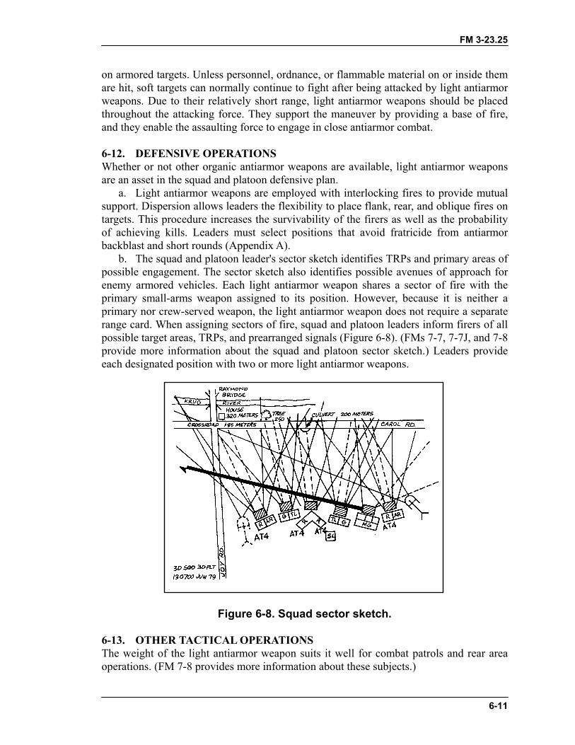
b. The squad and platoon leader's sector sketch identifies TRPs and primary areas ofpossible engagement. The sector sketch also identifies possible avenues of approach forenemy armored vehicles. Each light antiarmor weapon shares a sector of fire with theprimary small-arms weapon assigned to its position. However, because it is neither aprimary nor crew-served weapon, the light antiarmor weapon does not require a separaterange card. When assigning sectors of fire, squad and platoon leaders inform firers of allpossible target areas, TRPs, and prearranged signals (Figure 6-8). (FMs 7-7, 7-7J, and 7-8provide more information about the squad and platoon sector sketch.) Leaders provideeach designated position with two or more light antiarmor weapons.
Figure 6-8. Squad sector sketch.
6-13. OTHER TACTICAL OPERATIONSThe weight of the light antiarmor weapon suits it well for combat patrols and rear areaoperations. (FM 7-8 provides more information about these subjects.)
FM 3-23.25
6-12
a. Combat Patrols. Light antiarmor weapons are used on combat patrols to destroyenemy equipment, installations, and key points, and to harass enemy forces. The twotypes of combat patrols are―
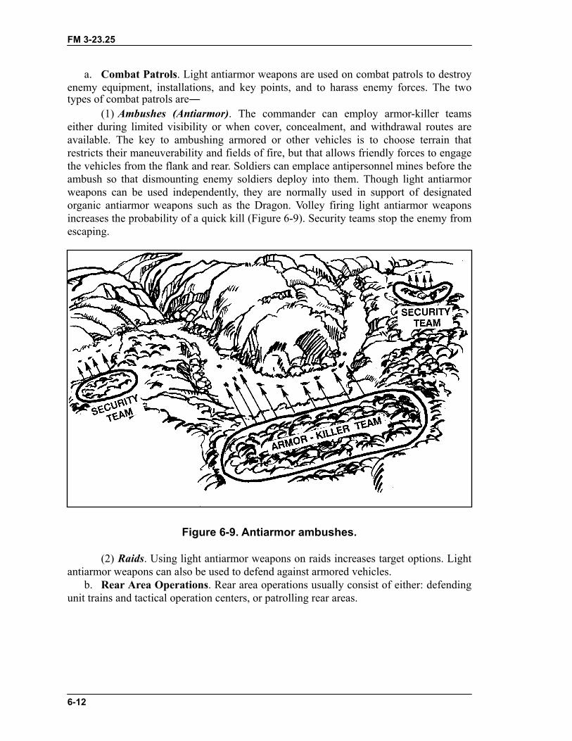
(1) Ambushes (Antiarmor). The commander can employ armor-killer teamseither during limited visibility or when cover, concealment, and withdrawal routes areavailable. The key to ambushing armored or other vehicles is to choose terrain thatrestricts their maneuverability and fields of fire, but that allows friendly forces to engagethe vehicles from the flank and rear. Soldiers can emplace antipersonnel mines before theambush so that dismounting enemy soldiers deploy into them. Though light antiarmorweapons can be used independently, they are normally used in support of designatedorganic antiarmor weapons such as the Dragon. Volley firing light antiarmor weaponsincreases the probability of a quick kill (Figure 6-9). Security teams stop the enemy fromescaping.
Figure 6-9. Antiarmor ambushes.
(2) Raids. Using light antiarmor weapons on raids increases target options. Lightantiarmor weapons can also be used to defend against armored vehicles.
b. Rear Area Operations. Rear area operations usually consist of either: defendingunit trains and tactical operation centers, or patrolling rear areas.

FM 3-23.25
6-13
(1) Defense of Tactical Operations Center and Unit Trains. The mobility ofmodern vehicles makes the TOC and unit trains prime targets. Light antiarmor weaponsare used to engage vehicles threatening the unit during the defense of the TOC. Soldierswho use light antiarmor weapons in this type of operation normally perform noninfantry-type roles. Unit leaders designate soldiers to carry light antiarmor weapons and ensurethat these soldiers receive light antiarmor weapons training.
(2) Patrols of Rear Areas. Rear area patrols are security patrols conducted bydesignated infantry or MP units. These patrols can react to any threat they encounter inthe rear area. Rear area patrols use the light antiarmor weapon in a hasty point defense ata roadblock, intersection, or strongpoint.
FM 3-23.25
7-1
CHAPTER 7TRAIN-THE-TRAINER AND UNIT TRAINING
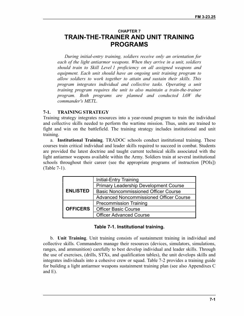
PROGRAMSDuring initial-entry training, soldiers receive only an orientation for
each of the light antiarmor weapons. When they arrive in a unit, soldiersshould train to Skill Level 1 proficiency on all assigned weapons andequipment. Each unit should have an ongoing unit training program toallow soldiers to work together to attain and sustain their skills. Thisprogram integrates individual and collective tasks. Operating a unittraining program requires the unit to also maintain a train-the-trainerprogram. Both programs are planned and conducted IAW thecommander's METL.
7-1. TRAINING STRATEGYTraining strategy integrates resources into a year-round program to train the individualand collective skills needed to perform the wartime mission. Thus, units are trained tofight and win on the battlefield. The training strategy includes institutional and unittraining.
a. Institutional Training. TRADOC schools conduct institutional training. Thesecourses train critical individual and leader skills required to succeed in combat. Studentsare provided the latest doctrine and taught current technical skills associated with thelight antiarmor weapons available within the Army. Soldiers train at several institutionalschools throughout their career (see the appropriate programs of instruction [POIs])(Table 7-1).
Initial-Entry TrainingPrimary Leadership Development CourseBasic Noncommissioned Officer CourseENLISTEDAdvanced Noncommissioned Officer CoursePrecommission TrainingOfficer Basic CourseOFFICERSOfficer Advanced Course
Table 7-1. Institutional training.
b. Unit Training. Unit training consists of sustainment training in individual andcollective skills. Commanders manage their resources (devices, simulators, simulations,ranges, and ammunition) carefully to best develop individual and leader skills. Throughthe use of exercises, (drills, STXs, and qualification tables), the unit develops skills andintegrates individuals into a cohesive crew or squad. Table 7-2 provides a training guidefor building a light antiarmor weapons sustainment training plan (see also Appendixes Cand E).
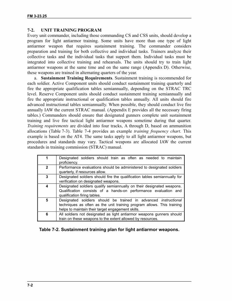
FM 3-23.25
7-2
7-2. UNIT TRAINING PROGRAMEvery unit commander, including those commanding CS and CSS units, should develop aprogram for light antiarmor training. Some units have more than one type of lightantiarmor weapon that requires sustainment training. The commander considerspreparation and training for both collective and individual tasks. Trainers analyze theircollective tasks and the individual tasks that support them. Individual tasks must beintegrated into collective training and rehearsals. The units should try to train lightantiarmor weapons at the same time and on the same range (Appendix D). Otherwise,these weapons are trained in alternating quarters of the year.
a. Sustainment Training Requirements. Sustainment training is recommended foreach soldier. Active Component units should conduct sustainment training quarterly andfire the appropriate qualification tables semiannually, depending on the STRAC TRClevel. Reserve Component units should conduct sustainment training semiannually andfire the appropriate instructional or qualification tables annually. All units should fireadvanced instructional tables semiannually. When possible, they should conduct live fireannually IAW the current STRAC manual. (Appendix E provides all the necessary firingtables.) Commanders should ensure that designated gunners complete unit sustainmenttraining and live fire tactical light antiarmor weapons sometime during that quarter.Training requirements are divided into four tracks, A through D, based on ammunitionallocations (Table 7-3). Table 7-4 provides an example training frequency chart. Thisexample is based on the AT4. The same tasks apply to all light antiarmor weapons, butprocedures and standards may vary. Tactical weapons are allocated IAW the currentstandards in training commission (STRAC) manual.
1 Designated soldiers should train as often as needed to maintainproficiency.
2 Performance evaluations should be administered to designated soldiersquarterly, if resources allow.
3 Designated soldiers should fire the qualification tables semiannually forverification on designated weapons.
4 Designated soldiers qualify semiannually on their designated weapons.Qualification consists of a hands-on performance evaluation andqualification firing tables.
5 Designated soldiers should be trained in advanced instructionaltechniques as often as the unit training program allows. This traininghelps to maintain their target engagement skills.
6 All soldiers not designated as light antiarmor weapons gunners shouldtrain on these weapons to the extent allowed by resources.
Table 7-2. Sustainment training plan for light antiarmor weapons.
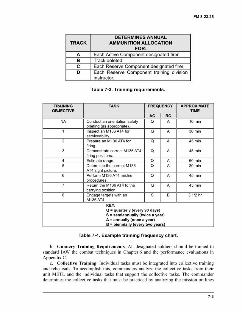
FM 3-23.25
7-3
TRACKDETERMINES ANNUAL
AMMUNITION ALLOCATIONFOR:
A Each Active Component designated firer.B Track deletedC Each Reserve Component designated firer.D Each Reserve Component training division
instructor.
Table 7-3. Training requirements.
TRAININGOBJECTIVE
TASK FREQUENCY APPROXIMATETIME
AC RCNA Conduct an orientation safety
briefing (as appropriate).Q A 10 min
1 Inspect an M136 AT4 forserviceability.
Q A 30 min
2 Prepare an M136 AT4 forfiring.
Q A 45 min
3 Demonstrate correct M136 AT4firing positions.
Q A 45 min
4 Estimate range. Q A 60 min5 Determine the correct M136
AT4 sight picture.Q A 30 min
6 Perform M136 AT4 misfireprocedures.
Q A 45 min
7 Return the M136 AT4 to thecarrying position.
Q A 45 min
8 Engage targets with anM136 AT4.
S B 3 1/2 hr
KEY:Q = quarterly (every 90 days)S = semiannually (twice a year)A = annually (once a year)B = biennially (every two years)
Table 7-4. Example training frequency chart.
b. Gunnery Training Requirements. All designated soldiers should be trained tostandard IAW the combat techniques in Chapter 6 and the performance evaluations inAppendix C.
c. Collective Training. Individual tasks must be integrated into collective trainingand rehearsals. To accomplish this, commanders analyze the collective tasks from theirunit METL and the individual tasks that support the collective tasks. The commanderdetermines the collective tasks that must be practiced by analyzing the mission outlines
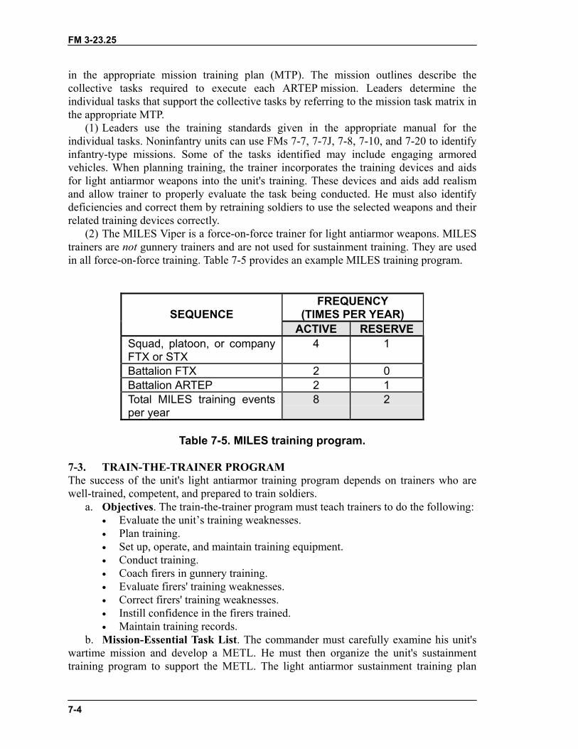
FM 3-23.25
7-4
in the appropriate mission training plan (MTP). The mission outlines describe thecollective tasks required to execute each ARTEP mission. Leaders determine theindividual tasks that support the collective tasks by referring to the mission task matrix inthe appropriate MTP.
(1) Leaders use the training standards given in the appropriate manual for theindividual tasks. Noninfantry units can use FMs 7-7, 7-7J, 7-8, 7-10, and 7-20 to identifyinfantry-type missions. Some of the tasks identified may include engaging armoredvehicles. When planning training, the trainer incorporates the training devices and aidsfor light antiarmor weapons into the unit's training. These devices and aids add realismand allow trainer to properly evaluate the task being conducted. He must also identifydeficiencies and correct them by retraining soldiers to use the selected weapons and theirrelated training devices correctly.
(2) The MILES Viper is a force-on-force trainer for light antiarmor weapons. MILEStrainers are not gunnery trainers and are not used for sustainment training. They are usedin all force-on-force training. Table 7-5 provides an example MILES training program.
FREQUENCY(TIMES PER YEAR)SEQUENCE
ACTIVE RESERVESquad, platoon, or companyFTX or STX
4 1
Battalion FTX 2 0Battalion ARTEP 2 1Total MILES training eventsper year
8 2
Table 7-5. MILES training program.
7-3. TRAIN-THE-TRAINER PROGRAMThe success of the unit's light antiarmor training program depends on trainers who arewell-trained, competent, and prepared to train soldiers.
a. Objectives. The train-the-trainer program must teach trainers to do the following:• Evaluate the unit’s training weaknesses.• Plan training.• Set up, operate, and maintain training equipment.• Conduct training.• Coach firers in gunnery training.• Evaluate firers' training weaknesses.• Correct firers' training weaknesses.• Instill confidence in the firers trained.• Maintain training records.
b. Mission-Essential Task List. The commander must carefully examine his unit'swartime mission and develop a METL. He must then organize the unit's sustainmenttraining program to support the METL. The light antiarmor sustainment training plan
FM 3-23.25
7-5
consists of quarterly, semiannual, and annual training events. Between these events, theunit provides additional light antiarmor weapons training. The sustainment plan shouldprepare the unit for the next round of weapons gunnery while also supporting the unitMETL.
c. Trainer Assessment. Trainers within a unit are normally team, squad, and sectionleaders and platoon sergeants. Before becoming weapons trainers, they must be assessedcarefully and any shortcomings corrected. The commander chooses a method ofassessing the trainers that ensures that their abilities are accurately evaluated. Then, withthe assistance of the platoon leaders and platoon sergeants, the commander performs thisassessment.
d. Command Benefits. Regular and aggressive train-the-trainer programs providevaluable benefits that gradually spread through the unit. These benefits include a base ofexpertise, proficiency, and esprit de corps. Maintaining this base is easier than recreatingit.
e. Training Tasks. Successful trainers know how to operate the training devices forthe light antiarmor weapons assigned to their units. Based on the unit's METL, thecommander designates the appropriate light antiarmor weapon for specified missions.Appendix C provides the tasks, conditions, and standards for each weapon discussed inthis manual. The trainers must know the appropriate combat techniques for employingthese weapons. They must also perform the following:
• Conduct an orientation safety briefing.• Inspect the weapons for serviceability.• Prepare the weapons for firing.• Demonstrate the correct firing positions.• Estimate range.• Determine the correct sight picture.• Perform the correct combat and training misfire procedures.• Return the weapon to the carrying configuration.
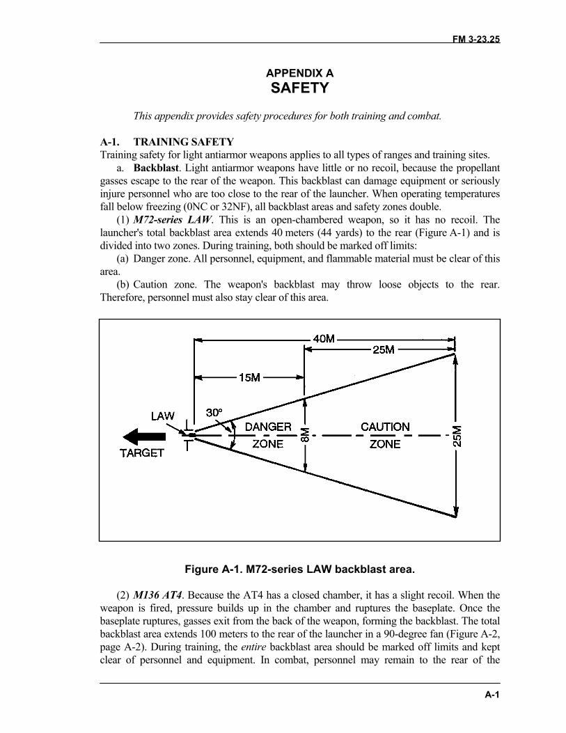
FM 3-23.25
A-1
APPENDIX ASAFETY
This appendix provides safety procedures for both training and combat.
A-1. TRAINING SAFETYTraining safety for light antiarmor weapons applies to all types of ranges and training sites.
a. Backblast. Light antiarmor weapons have little or no recoil, because the propellantgasses escape to the rear of the weapon. This backblast can damage equipment or seriouslyinjure personnel who are too close to the rear of the launcher. When operating temperaturesfall below freezing (0NC or 32NF), all backblast areas and safety zones double.
(1) M72-series LAW. This is an open-chambered weapon, so it has no recoil. Thelauncher's total backblast area extends 40 meters (44 yards) to the rear (Figure A-1) and isdivided into two zones. During training, both should be marked off limits:
(a) Danger zone. All personnel, equipment, and flammable material must be clear of thisarea.
(b) Caution zone. The weapon's backblast may throw loose objects to the rear.Therefore, personnel must also stay clear of this area.
Figure A-1. M72-series LAW backblast area.
(2) M136 AT4. Because the AT4 has a closed chamber, it has a slight recoil. When theweapon is fired, pressure builds up in the chamber and ruptures the baseplate. Once thebaseplate ruptures, gasses exit from the back of the weapon, forming the backblast. The totalbackblast area extends 100 meters to the rear of the launcher in a 90-degree fan (Figure A-2,page A-2). During training, the entire backblast area should be marked off limits and keptclear of personnel and equipment. In combat, personnel may remain to the rear of the
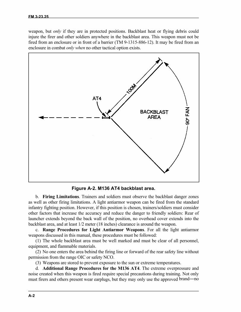
FM 3-23.25
A-2
weapon, but only if they are in protected positions. Backblast heat or flying debris couldinjure the firer and other soldiers anywhere in the backblast area. This weapon must not befired from an enclosure or in front of a barrier (TM 9-1315-886-12). It may be fired from anenclosure in combat only when no other tactical option exists.
Figure A-2. M136 AT4 backblast area.b. Firing Limitations. Trainers and soldiers must observe the backblast danger zones
as well as other firing limitations. A light antiarmor weapon can be fired from the standardinfantry fighting position. However, if this position is chosen, trainers/soldiers must considerother factors that increase the accuracy and reduce the danger to friendly soldiers: Rear oflauncher extends beyond the back wall of the position, no overhead cover extends into thebackblast area, and at least 1/2 meter (18 inches) clearance is around the weapon.
c. Range Procedures for Light Antiarmor Weapons. For all the light antiarmorweapons discussed in this manual, these procedures must be followed:
(1) The whole backblast area must be well marked and must be clear of all personnel,equipment, and flammable materials.
(2) No one enters the area behind the firing line or forward of the rear safety line withoutpermission from the range OIC or safety NCO.
(3) Weapons are stored to prevent exposure to the sun or extreme temperatures.d. Additional Range Procedures for the M136 AT4. The extreme overpressure and
noise created when this weapon is fired require special precautions during training. Not onlymust firers and others present wear earplugs, but they may only use the approved brand―no
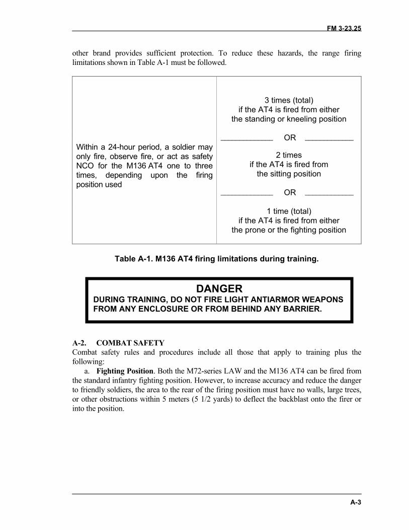
FM 3-23.25
A-3
other brand provides sufficient protection. To reduce these hazards, the range firinglimitations shown in Table A-1 must be followed.
3 times (total)if the AT4 is fired from either
the standing or kneeling position
______________ _____________OR
2 timesif the AT4 is fired from
the sitting position
______________ OR _____________
Within a 24-hour period, a soldier mayonly fire, observe fire, or act as safetyNCO for the M136 AT4 one to threetimes, depending upon the firingposition used
1 time (total)if the AT4 is fired from either
the prone or the fighting position
Table A-1. M136 AT4 firing limitations during training.
A-2. COMBAT SAFETYCombat safety rules and procedures include all those that apply to training plus thefollowing:
a. Fighting Position. Both the M72-series LAW and the M136 AT4 can be fired fromthe standard infantry fighting position. However, to increase accuracy and reduce the dangerto friendly soldiers, the area to the rear of the firing position must have no walls, large trees,or other obstructions within 5 meters (5 1/2 yards) to deflect the backblast onto the firer orinto the position.
DANGERDURING TRAINING, DO NOT FIRE LIGHT ANTIARMOR WEAPONSFROM ANY ENCLOSURE OR FROM BEHIND ANY BARRIER.

FM 3-23.25
A-4
(1) In the individual infantry fighting position, the soldier must lean against the rear walland ensure that the venturi or the rear of the weapon protrudes past the rear of the position.The firer's elbows are not supported.
(2) In the two-soldier infantry fighting position, the nonfiring soldier must remain clearof the backblast area. These positions should be constructed and sited so that none arelocated in another's backblast danger zone.
(3) A modified firing position may be constructed to the side of the two-soldier fightingposition. Firing from a modified position reduces the possibility of injury to the firer oranother soldier in the fighting position, but it offers the firer some protection from enemyreturn fire.
b. Temperature Limitations. No light antiarmor weapon should be fired when itstemperature exceeds operating limits. When a weapon temperature is below freezing(0 degrees Centigrade or 32 degrees Fahrenheit), overpressure increases and prevents someof the propellant from burning. Then, as the projectile leaves the launch tube, portions of theremaining propellant could be directed onto the firer's face or upper body. Consequently, incold weather, the firer should wear a protective mask. On the other hand, when the weapontemperature is above 60 degrees Centigrade (140 degrees Fahrenheit), propellants andwarhead compounds can destabilize, so, whether they are located at training sites or fightingpositions, weapons should be stored in a shaded area in hot weather. Finally, weapons mustnot be fired when their temperatures exceed safe operating limits: -40 degrees to 60 degreesCentigrade (-40 degrees to +140 degrees Fahrenheit).
c. Minimum Target Engagement Ranges. In combat, no targets will be engagedwithin the 10-meter minimum arming range. During training, no targets will be engagedwithin 30 meters.
d. Overhead Fire. Light antiarmor weapons must not be fired over the heads offriendly soldiers, unless the soldiers have adequate protection against direct impact or otherhazards.
DANGERENSURE THE AREA TO THE REAR OF THE FIRINGPOSITION HAS NO WALLS, LARGE TREES, OR OTHEROBSTRUCTIONS WITIN 5 METERS (5 1/2 YARDS). OBSTRUCTIONS DEFLECT BACKBLAST ONTO THEFIRER OR INTO THE POSITION, INJURING OR KILLINGTHE FIRER AND ANY OTHER SOLDIER OCCUPYING THEFIRING POSITION.

FM 3-23.25
B-1
APPENDIX BTRAINING DEVICES AND AIDS
Training devices and training aids enable soldiers to learn as much asthey can about a weapon before they try the real thing. This proceduresaves money and time, and it prevents injuries. Training devices both lookand behave like the real weapon, but are cheaper and safer to practicewith. Training aids include anything else used to help soldiers learn touse a weapon. Trainers should use their imaginations and invent or adaptother training aids from available resources.
B-1. LAW SUBCALIBER TRAINING DEVICEThe only M72-series LAW training device designed for individual use is a subcalibertrainer (Figure B-1). This device, referred to as the M190 subcaliber launcher, is made byadding an M190 subcaliber conversion kit (NSN 1340-00-420-7999) (Figure B-2) to anexpended M72-series LAW launcher. It is used to fire the M73 subcaliber (35-mm)rocket. This 36-mm rocket is shorter and lighter than the LAW's 66-mm tactical rocket. Itsimulates the tactical rocket's smoke and flight trajectory but with less noise andbackblast. The expended launcher is likely to wear out before the subcaliber inner tubedoes. When this happens, the inner tube can be transferred to another expended launcher.The M190 subcaliber launcher can be used in all training phases, from a fixed firing lineto simulated tactical situations such as a squad live-fire exercise.
NOTE: The local Training Support Center (TSC) can install the conversion kits, butDOD Regulation 5100.76-M requires that all sensitive conventional arms,ammunitions, and explosives, including expended launchers, be carefullycontrolled.
Figure B-1. LAW subcaliber trainer.
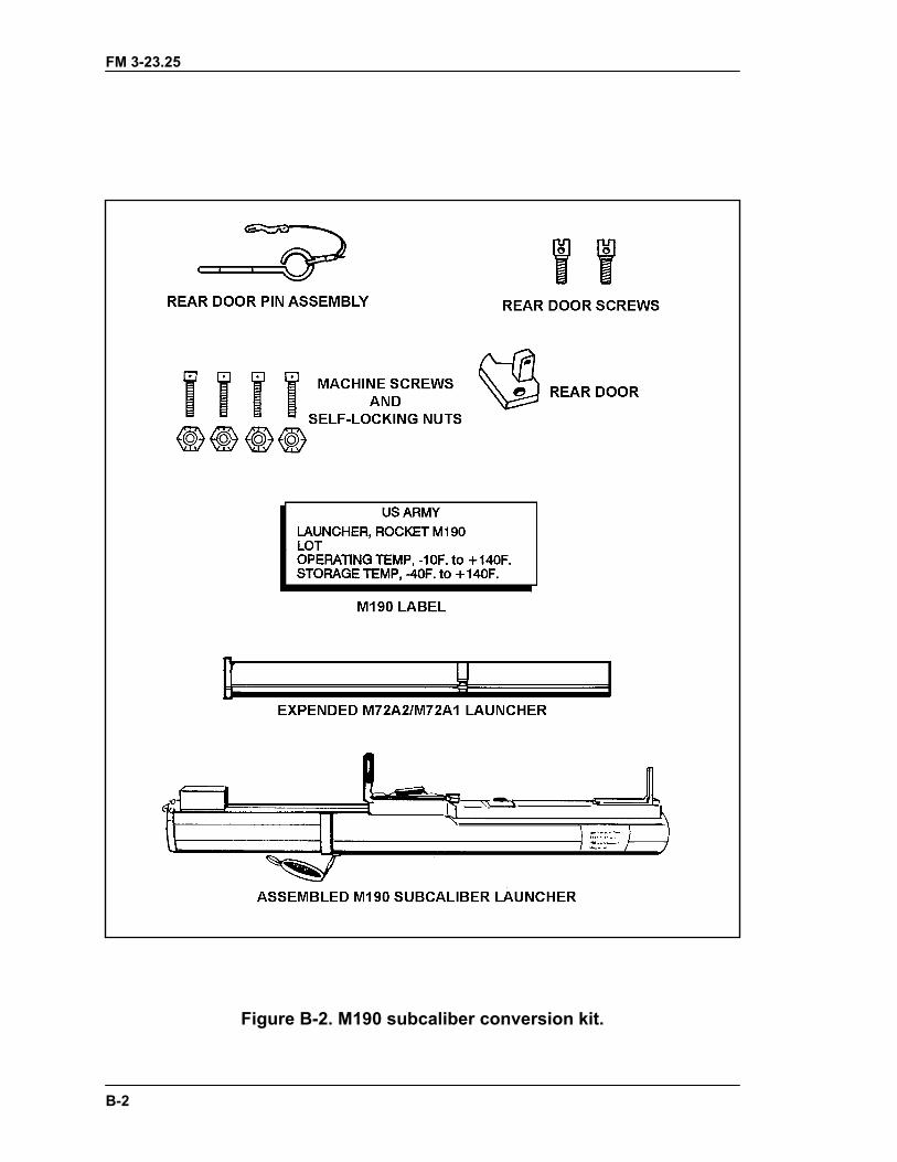
FM 3-23.25
B-2
Figure B-2. M190 subcaliber conversion kit.
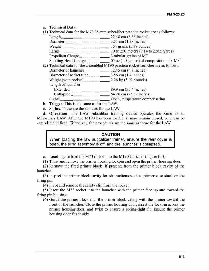
FM 3-23.25
a. Technical Data.(1) Technical data for the M73 35-mm subcaliber practice rocket are as follows:
Length................................................ 22.48 cm (8.86 inches)Diameter ............................................ 3.51 cm (1.38 inches)Weight ............................................... 154 grams (5.39 ounces)Range................................................. 10 to 250 meters (9.14 to 228.5 yards)Propellant Charge.............................. 3 tubular grains of M7Spotting Head Charge ....................... 05 oz (1.5 grams) of composition mix M80
(2) Technical data for the assembled M190 practice rocket launcher are as follows:Diameter of launcher......................... 12.45 cm (4.9 inches)Diameter of rocket tube..................... 3.56 cm (1.4 inches)Weight (with rocket).......................... 2.26 kg (5.02 pounds)Length of launcher
Extended....................................... 89.9 cm (35.4 inches)Collapsed ...................................... 64.26 cm (25.32 inches)
Sights................................................. Open, temperature compensatingb. Trigger. This is the same as for the LAW.c. Sights. These are the same as for the LAW.d. Operation. The LAW subcaliber training device operates the same as an
M72-series LAW. After the M190 has been loaded, it may remain closed, or it can beextended and fired. Either way, the procedures are the same as those for the LAW.
e. Loading. To load the M73 roc(1) Twist and remove the primer h(2) Remove the fired primer bloc
launcher.(3) Inspect the primer block cavit
firing pin.(4) Pivot and remove the safety cli(5) Insert the M73 rocket into the
firing pin housing.(6) Guide the primer block into t
front of the launcher. Close theprimer housing door, and twihousing door fits snugly.
When loading the law subcopen, the sling assembly is
CAUTIONaliber trainer, ensure the rear cover isoff, and the launcher is collapsed.
B-3
ket into the M190 launcher (Figure B-3)―ousing lockpin and open the primer housing door.k (if present) from the primer block cavity of the
y for obstructions such as primer case stuck on the
p from the rocket. launcher with the primer face up and toward the
he primer block cavity with the primer toward the primer housing door, insert the lockpin across thest to ensure a spring-tight fit. Ensure the primer
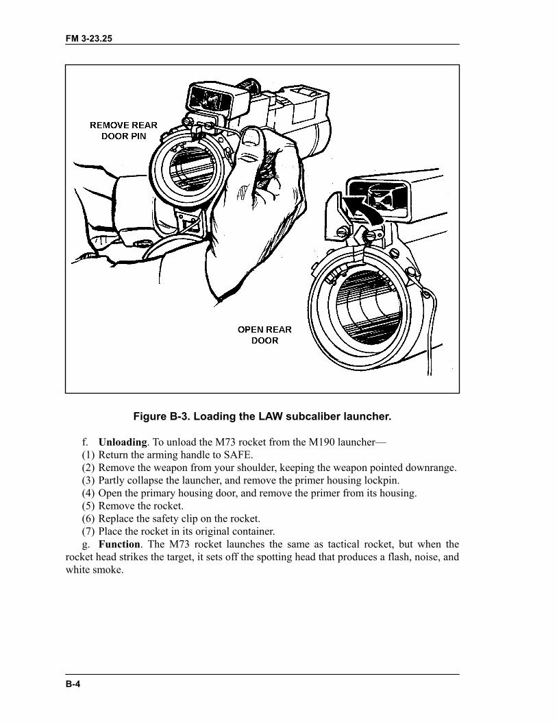
FM 3-23.25
B-4
Figure B-3. Loading the LAW subcaliber launcher.
f. Unloading. To unload the M73 rocket from the M190 launcher—(1) Return the arming handle to SAFE.(2) Remove the weapon from your shoulder, keeping the weapon pointed downrange.(3) Partly collapse the launcher, and remove the primer housing lockpin.(4) Open the primary housing door, and remove the primer from its housing.(5) Remove the rocket.(6) Replace the safety clip on the rocket.(7) Place the rocket in its original container.g. Function. The M73 rocket launches the same as tactical rocket, but when the
rocket head strikes the target, it sets off the spotting head that produces a flash, noise, andwhite smoke.
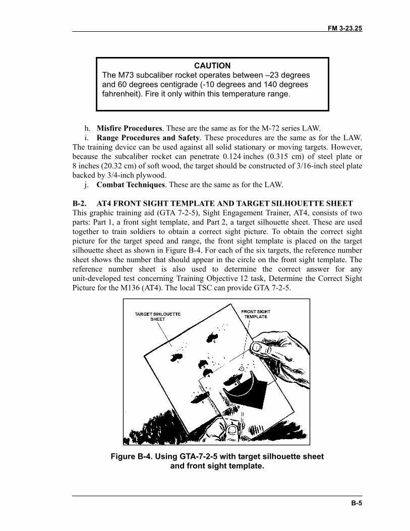
FM 3-23.25
B-5
h. Misfire Procedures. These are the same as for the M-72 series LAW.i. Range Procedures and Safety. These procedures are the same as for the LAW.
The training device can be used against all solid stationary or moving targets. However,because the subcaliber rocket can penetrate 0.124 inches (0.315 cm) of steel plate or8 inches (20.32 cm) of soft wood, the target should be constructed of 3/16-inch steel platebacked by 3/4-inch plywood.
j. Combat Techniques. These are the same as for the LAW.
B-2. AT4 FRONT SIGHT TEMPLATE AND TARGET SILHOUETTE SHEETThis graphic training aid (GTA 7-2-5), Sight Engagement Trainer, AT4, consists of twoparts: Part 1, a front sight template, and Part 2, a target silhouette sheet. These are usedtogether to train soldiers to obtain a correct sight picture. To obtain the correct sightpicture for the target speed and range, the front sight template is placed on the targetsilhouette sheet as shown in Figure B-4. For each of the six targets, the reference numbersheet shows the number that should appear in the circle on the front sight template. Thereference number sheet is also used to determine the correct answer for anyunit-developed test concerning Training Objective 12 task, Determine the Correct SightPicture for the M136 (AT4). The local TSC can provide GTA 7-2-5.
Figure B-4. Using GTA-7-2-5 with target silhouette sheetand front sight template.
CAUTIONThe M73 subcaliber rocket operates between –23 degreesand 60 degrees centigrade (-10 degrees and 140 degreesfahrenheit). Fire it only within this temperature range.
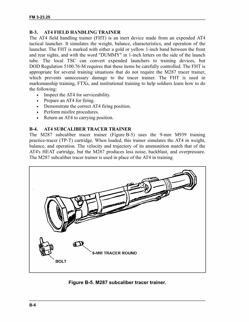
FM 3-23.25
B-6
B-3. AT4 FIELD HANDLING TRAINERThe AT4 field handling trainer (FHT) is an inert device made from an expended AT4tactical launcher. It simulates the weight, balance, characteristics, and operation of thelauncher. The FHT is marked with either a gold or yellow 1-inch band between the frontand rear sights, and with the word "DUMMY" in 1-inch letters on the side of the launchtube. The local TSC can convert expended launchers to training devices, butDOD Regulation 5100.76-M requires that these items be carefully controlled. The FHT isappropriate for several training situations that do not require the M287 tracer trainer,which prevents unnecessary damage to the tracer trainer. The FHT is used inmarksmanship training, FTXs, and institutional training to help soldiers learn how to dothe following:
• Inspect the AT4 for serviceability.• Prepare an AT4 for firing.• Demonstrate the correct AT4 firing position.• Perform misfire procedures.• Return an AT4 to carrying position.
B-4. AT4 SUBCALIBER TRACER TRAINERThe M287 subcaliber tracer trainer (Figure B-5) uses the 9-mm M939 trainingpractice-tracer (TP-T) cartridge. When loaded, this trainer simulates the AT4 in weight,balance, and operation. The velocity and trajectory of its ammunition match that of theAT4's HEAT cartridge, but the M287 produces less noise, backblast, and overpressure.The M287 subcaliber tracer trainer is used in place of the AT4 in training.
Figure B-5. M287 subcaliber tracer trainer.
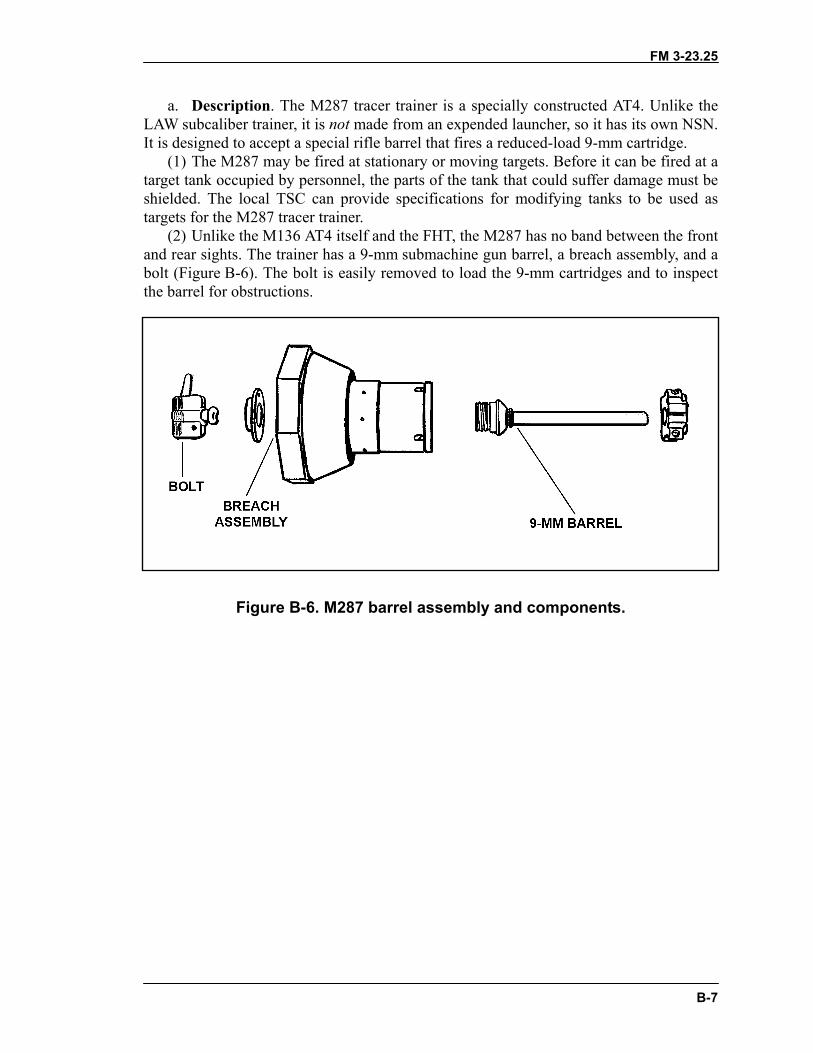
FM 3-23.25
B-7
a. Description. The M287 tracer trainer is a specially constructed AT4. Unlike theLAW subcaliber trainer, it is not made from an expended launcher, so it has its own NSN.It is designed to accept a special rifle barrel that fires a reduced-load 9-mm cartridge.
(1) The M287 may be fired at stationary or moving targets. Before it can be fired at atarget tank occupied by personnel, the parts of the tank that could suffer damage must beshielded. The local TSC can provide specifications for modifying tanks to be used astargets for the M287 tracer trainer.
(2) Unlike the M136 AT4 itself and the FHT, the M287 has no band between the frontand rear sights. The trainer has a 9-mm submachine gun barrel, a breach assembly, and abolt (Figure B-6). The bolt is easily removed to load the 9-mm cartridges and to inspectthe barrel for obstructions.
Figure B-6. M287 barrel assembly and components.
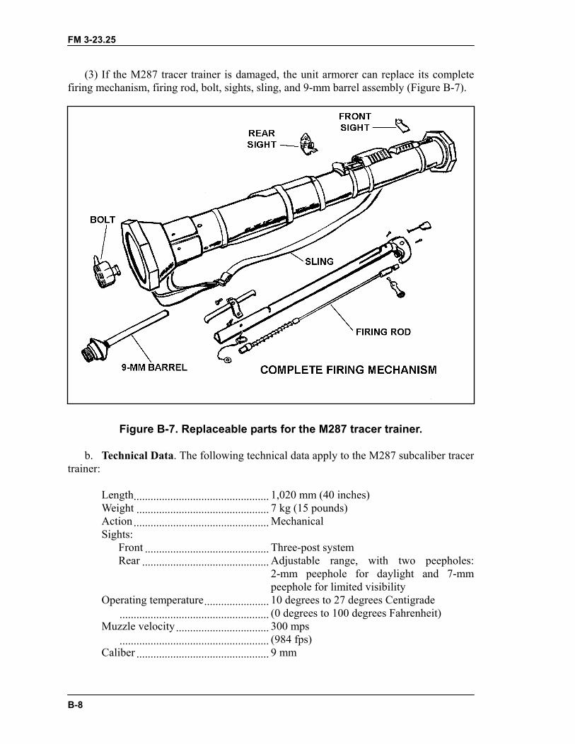
FM 3-23.25
B-8
(3) If the M287 tracer trainer is damaged, the unit armorer can replace its completefiring mechanism, firing rod, bolt, sights, sling, and 9-mm barrel assembly (Figure B-7).
Figure B-7. Replaceable parts for the M287 tracer trainer.
b. Technical Data. The following technical data apply to the M287 subcaliber tracertrainer:
Length................................................ 1,020 mm (40 inches)Weight ............................................... 7 kg (15 pounds)Action ................................................ MechanicalSights:
Front ............................................ Three-post systemRear ............................................. Adjustable range, with two peepholes:
2-mm peephole for daylight and 7-mmpeephole for limited visibility
Operating temperature....................... 10 degrees to 27 degrees Centigrade..................................................... (0 degrees to 100 degrees Fahrenheit)
Muzzle velocity................................. 300 mps..................................................... (984 fps)
Caliber ............................................... 9 mm
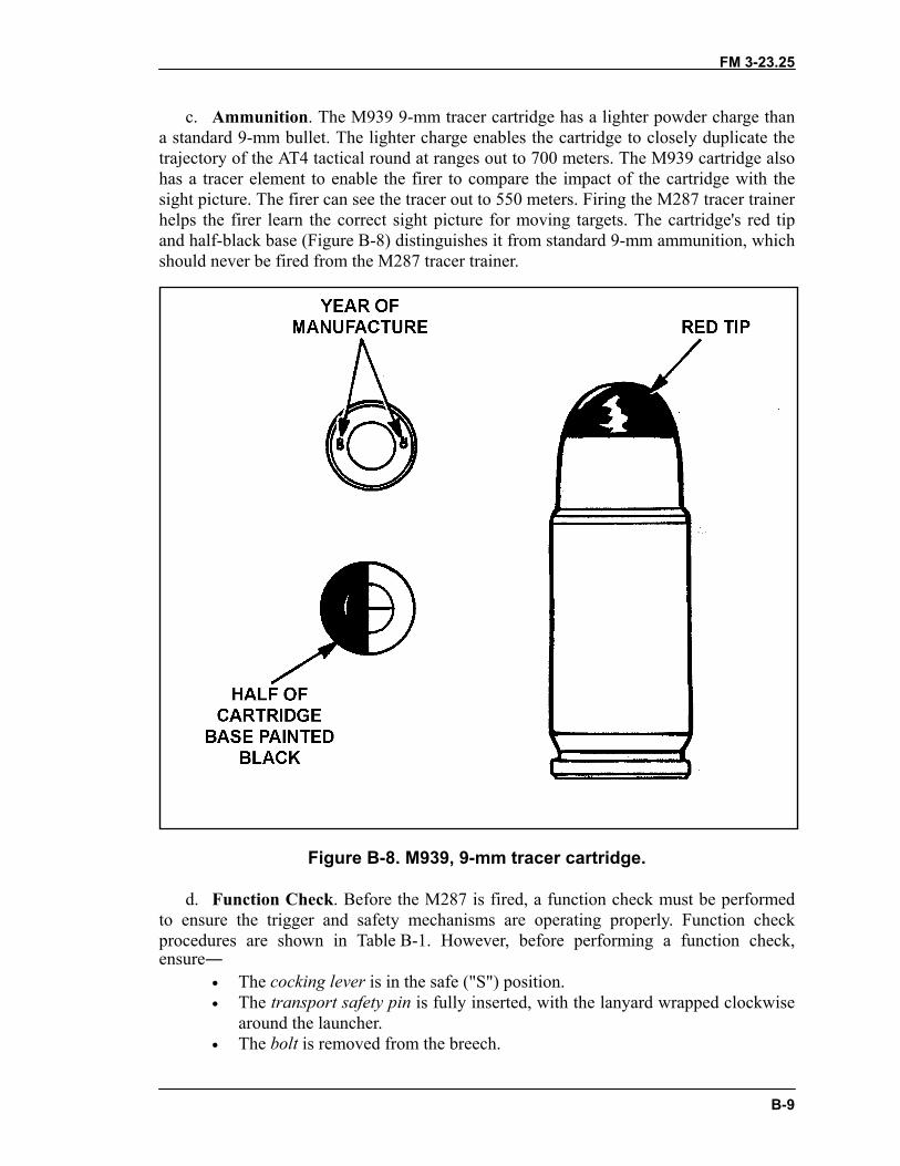
FM 3-23.25
B-9
c. Ammunition. The M939 9-mm tracer cartridge has a lighter powder charge thana standard 9-mm bullet. The lighter charge enables the cartridge to closely duplicate thetrajectory of the AT4 tactical round at ranges out to 700 meters. The M939 cartridge alsohas a tracer element to enable the firer to compare the impact of the cartridge with thesight picture. The firer can see the tracer out to 550 meters. Firing the M287 tracer trainerhelps the firer learn the correct sight picture for moving targets. The cartridge's red tipand half-black base (Figure B-8) distinguishes it from standard 9-mm ammunition, whichshould never be fired from the M287 tracer trainer.
Figure B-8. M939, 9-mm tracer cartridge.
d. Function Check. Before the M287 is fired, a function check must be performedto ensure the trigger and safety mechanisms are operating properly. Function checkprocedures are shown in Table B-1. However, before performing a function check,ensure―
• The cocking lever is in the safe ("S") position.• The transport safety pin is fully inserted, with the lanyard wrapped clockwise
around the launcher.• The bolt is removed from the breech.
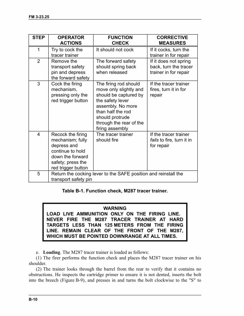
FM 3-23.25
B-10
STEP OPERATORACTIONS
FUNCTIONCHECK
CORRECTIVEMEASURES
1 Try to cock thetracer trainer
It should not cock If it cocks, turn thetrainer in for repair
2 Remove thetransport safetypin and depressthe forward safety
The forward safetyshould spring backwhen released
If it does not springback, turn the tracertrainer in for repair
3 Cock the firingmechanism,pressing only thered trigger button
The firing rod shouldmove only slightly andshould be captured bythe safety leverassembly. No morethan half the rodshould protrudethrough the rear of thefiring assembly
If the tracer trainerfires, turn it in forrepair
4 Recock the firingmechanism; fullydepress andcontinue to holddown the forwardsafety; press thered trigger button
The tracer trainershould fire
If the tracer trainerfails to fire, turn it infor repair
5 Return the cocking lever to the SAFE position and reinstall thetransport safety pin
Table B-1. Function check, M287 tracer trainer.
e. Loading. The M287 tracer tra(1) The firer performs the functio
shoulder.(2) The trainer looks through the
obstructions. He inspects the cartridginto the breech (Figure B-9), and pre
LOAD LIVE AMMUNITIONEVER FIRE THE M2TARGETS LESS THANLINE. REMAIN CLEAR WHICH MUST BE POINT
WARNINGN ONLY ON THE FIRING LINE.
87 TRACER TRAINER AT HARD 125 METERS FROM THE FIRING
OF THE FRONT OF THE M287,ED DOWNRANGE AT ALL TIMES.
iner is loaded as follows:n check and places the M287 tracer trainer on his
barrel from the rear to verify that it contains noe primer to ensure it is not dented, inserts the boltsses in and turns the bolt clockwise to the "S" to

FM 3-23.25
B-11
place it in the safe position (Figure B-10). Then he arms the tracer trainer by turning thebolt clockwise to "F" so that it can be fired (Figure B-11).
(3) With the launcher still on his shoulder, the firer cocks the launcher by placing thecocking lever in the cocked position.
Figure B-9. Inserting bolt with cartridge intothe breech of the M287 tracer trainer.
Figure B-10. Ensuring tracer trainer bolt is in the safe position.
Figure B-11. Arming the tracer trainer.
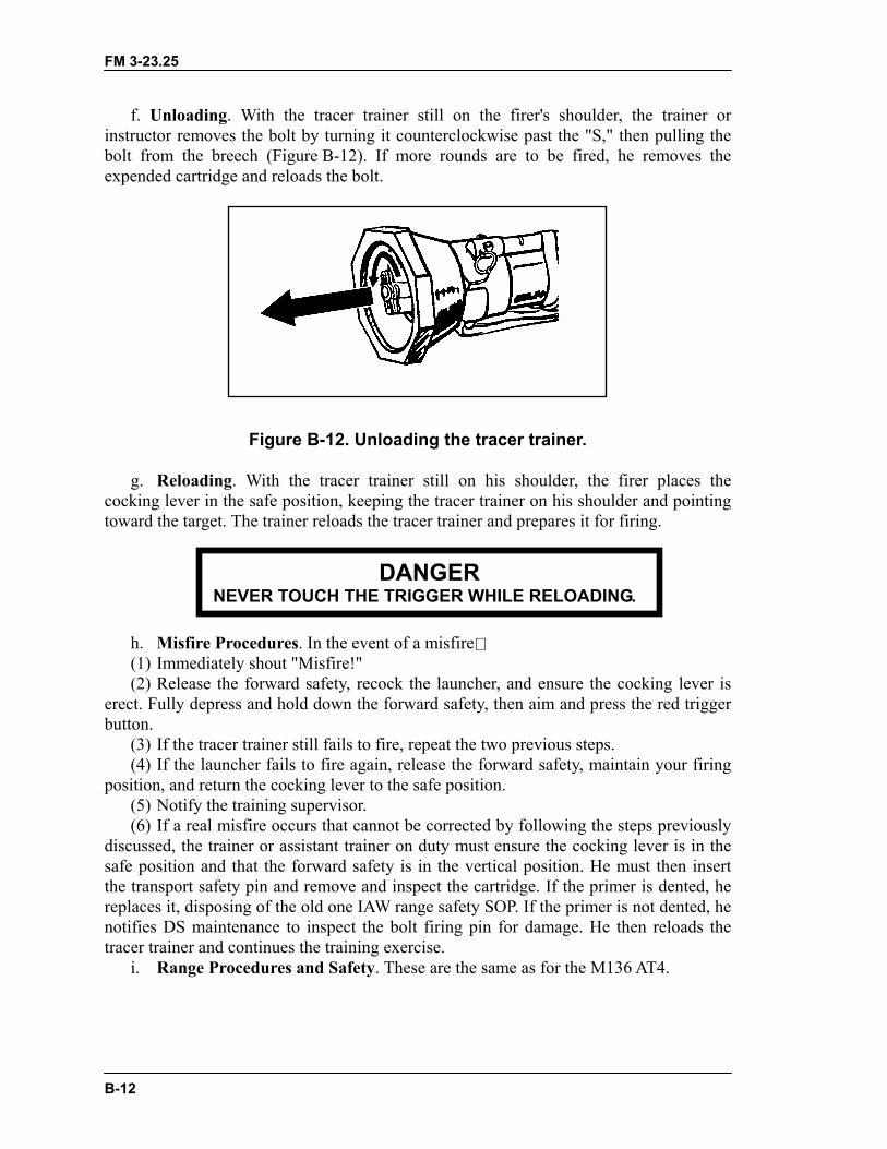
FM 3-23.25
B-12
f. Unloading. With the tracer trainer still on the firer's shoulder, the trainer orinstructor removes the bolt by turning it counterclockwise past the "S," then pulling thebolt from the breech (Figure B-12). If more rounds are to be fired, he removes theexpended cartridge and reloads the bolt.
Figure B-12. Unloading the tracer trainer.
g. Reloading. With the tracer trainer still on his shoulder, the firer places thecocking lever in the safe position, keeping the tracer trainer on his shoulder and pointingtoward the target. The trainer reloads the tracer trainer and prepares it for firing.
h. Misfire Procedures. In the eve(1) Immediately shout "Misfire!"(2) Release the forward safety, re
erect. Fully depress and hold down thbutton.
(3) If the tracer trainer still fails to(4) If the launcher fails to fire aga
position, and return the cocking lever t(5) Notify the training supervisor.(6) If a real misfire occurs that can
discussed, the trainer or assistant trainsafe position and that the forward safthe transport safety pin and remove anreplaces it, disposing of the old one IAnotifies DS maintenance to inspect thtracer trainer and continues the trainin
i. Range Procedures and Safety
NEVER TOUCH THE .
DANGER TRIGGER WHILE RELOADINGnt of a misfire
cock the launcher, and ensure the cocking lever ise forward safety, then aim and press the red trigger
fire, repeat the two previous steps.in, release the forward safety, maintain your firingo the safe position.
not be corrected by following the steps previouslyer on duty must ensure the cocking lever is in theety is in the vertical position. He must then insertd inspect the cartridge. If the primer is dented, heW range safety SOP. If the primer is not dented, hee bolt firing pin for damage. He then reloads the
g exercise.. These are the same as for the M136 AT4.
FM 3-23.25
C-1
APPENDIX CPERFORMANCE EVALUATIONS
The trainer administers performance evaluations to determine howmuch training the soldiers have learned. Those who fail are retrained andretested, and those who pass help retrain and evaluate those who did not.Instructions are given for right-handed firers: the M136 AT4 may only befired right-handed, but the M72-series LAW may be fired left-handed, ifprocedures are reversed. Tasks are generic to both light antiarmorweapons. Conditions and standards may also be generic but, if not, aregiven by weapon.
TASK 1: Perform serviceability checks on a light antiarmor weapon.
CONDITIONS: Given an expended light antiarmor weapon under suitable conditions orin an appropriate location.
M72-Series LAW
STANDARDS: The firer performs the following actions:
TRAINING AND EVALUATION
1. Inspects the launcher to ensure it has no cracks, dents, or bulges.
2. Ensures the trigger arming handle is present and in the SAFE position.
3. Checks the rubber boots around the trigger bar and detent for cracks, tears, anddeterioration.
4. (M72A2 only) Inspects the data plate on the right forward side of the launcher toensure the words "with coupler" appear on the first line. If not, informs the trainer.
M136 AT4
STANDARDS: The firer performs the following actions:
TRAINING AND EVALUATION
1. Ensures the launcher has no cracks, dents, or bulges, or reports these defects to theinstructor.
2. Ensures the transport safety pin is in place, or reports this defect to the instructor.
FM 3-23.25
C-2
3. Ensures the cocking lever is in the SAFE (uncocked) position, or reports this defect tothe instructor.
4. Ensures the muzzle cover is intact, or reports this defect to the instructor.
5. Ensures the color-coded band is correct, or reports this defect to the instructor.
6. Ensures the sights function properly, or reports this defect to the instructor.
7. Ensures the venturi has no foreign objects, or reports this defect to the instructor.
8. Ensures the forward safety functions properly, or reports this defect to the instructor.
9. Ensures the red trigger button is not broken or missing, or reports this defect to theinstructor.
10. Ensures the shoulder stop is not broken or damaged, or reports this defect to theinstructor.
11. Ensures the carrying sling is not frayed and is firmly attached to the launch tube, orreports this defect to the instructor.
RESULTS GO NO-GO
Critique and grade the soldier.
TASK 2: Place a light antiarmor weapon into operation.
CONDITIONS: Given an expended light antiarmor weapon (FHT) on a range or ingarrison.
M72-Series LAW
STANDARDS: The firer performs the following actions, in sequence:
TRAINING AND EVALUATION
1. Removes the rear cover pull pin.
2. Releases the rear cover and sling assembly.
3. Extends the launcher vigorously and ensures it is fully extended.
4. Places the launcher on his firing shoulder.
FM 3-23.25
C-3
5. Checks the backblast area.
6. Pulls the arming handle out.
7. Sights.
M136 AT4
STANDARDS: The firer performs the following actions, in sequence:
TRAINING AND EVALUATION
1. Cradles the AT4 in his arms.
2. Removes the transport safety pin.
3. Unsnaps and unfolds the shoulder stop.
4. Places the AT4 on his shoulder.
5. Releases the sights.
6. Checks the backblast area.
7. Places cocking lever in the ARMED (cocked) position.
8. Fully depresses and holds down the forward safety.
RESULTS GO NO-GO
Critique and grade the soldier.
TASK 3: Demonstrate the standing position used to fire a light antiarmor weapon.
CONDITIONS: Given a target and an expended light antiarmor weapon in any suitablelocation.
STANDARDS: The firer demonstrates the standing position as follows:
FM 3-23.25
C-4
TRAINING AND EVALUATION
M72-Series LAW
1. Faces the target by executing a half-left face turn and spreading feet a comfortabledistance apart.
2. Places the launcher on the shoulder with the left hand directly under the forwardportion of the launcher.
3. Places the right elbow against the body for stability.
M136 AT4
1. Faces the target by executing a half-left face turn and spreads the feet a comfortabledistance apart.
2. Places the launcher on the shoulder and grasps the sling near the launcher's muzzlewith the left hand.
3. Places the right elbow against the body for stability.
RESULTS GO NO-GO
Critique and grade the soldier.
TASK 4: Demonstrate the kneeling position used to fire a light antiarmor weapon.
CONDITIONS: Given a target and an expended light antiarmor weapon in a suitablelocation, with the soldier in the standing position.
STANDARDS: The firer demonstrates the kneeling position as follows:
TRAINING AND EVALUATION
1. Kneels on the right knee with the right thigh at a 90-degree angle to the line of aim.
2. Sits back on the right heel and shifts weight forward.
3. Rests the upper left arm forward of the left knee.
4. Places the right arm against the body.
FM 3-23.25
C-5
RESULTS GO NO-GO
Critique and grade the soldier.
TASK 5: Demonstrate the sitting position used to fire a light antiarmor weapon.
CONDITIONS: Given a light antiarmor weapon training device or expended launcher ina suitable location, with the soldier in the standing position.
STANDARDS: Each firer demonstrates the sitting position as follows:
TRAINING AND EVALUATION
1. Keeps the launcher pointed toward the target.
2. Executes a half-left face turn and sits with the legs crossed.
3. Places the launcher on the right shoulder.
4. Leans slightly forward from the hips.
5. Rests the elbows forward of the knees to avoid bone-to-bone contact.
RESULTS GO NO-GO
Critique and grade the soldier.
TASK 6: Demonstrate the prone position used to fire a light antiarmor weapon.
CONDITIONS: Given a target and an expended light antiarmor weapon (FHT) in asuitable location.
STANDARDS: The firer demonstrates the prone position as follows:
TRAINING AND EVALUATION
1. To keep clear of the backblast area, lies down at an angle of not less than 45 degreesfrom the line of fire.
2. Keeps back straight and right leg directly on line with the right hip and right shoulder.
3. Moves left leg as far as possible to ensure comfort.
4. Holds both elbows well below the launcher.
FM 3-23.25
C-6
5. Checks the backblast area to ensure that no part of the body is in it.
6. Holds head as steady as possible, with the firing eye lined up with the sights.
RESULTS GO NO-GO
Critique and grade the soldier.
TASK 7: Identify enemy vehicles and weapons.
CONDITIONS: Given ten vehicle identification cards (GTA 17-2-13).
STANDARDS: The soldier correctly identifies eight out of ten vehicles or weapons bynomenclature.
RESULTS GO NO-GO
Critique and grade the soldier.
TASK 8: Estimate range.
CONDITIONS: Given stationary, partly exposed, or fully exposed targets at rangesbetween 50 and 250 meters, during daylight, in weather conditions where all targets arevisible. Targets include personnel, equipment, silhouettes, and vehicles.
STANDARDS: The soldier states the distance to each target with no more than20 percent error.
RESULTS GO NO-GO
Critique and grade the soldier.
TASK 9: Apply the correct lead for a target.
CONDITIONS: Given a sight template, a series of ten flank, frontal, and obliquesilhouettes of armored targets, rates of movement, and ranges. (At least three differentviews, speeds, and ranges are given.)
STANDARDS: The soldier uses correct sighting procedures and correctly applies thelead eight out of ten times.
FM 3-23.25
C-7
RESULTS GO NO-GO
Critique and grade the soldier.
TASK 10: Perform misfire procedures on a light antiarmor weapon.
CONDITIONS: Given a previously fired light antiarmor weapon and instructions thatthe weapon has misfired, on a suitable firing range, under simulated combat conditions,in any lighting conditions.
M72-series LAW
STANDARDS: The soldier applies misfire procedures as follows and tries to fire theM72-series LAW. If the weapon still fails to fire, he disposes of it IAW unit SOP:
TRAINING AND EVALUATION
1. Immediately squeezes the trigger bar again.
2. If the LAW still does not fire, tries to place the trigger arming handle on SAFE.
3. Removes the launcher from the shoulder and partly collapses it (10 to 15 centimetersor 4 to 6 inches), keeping the launcher pointed upward and downrange.
4. Extends the launcher.
5. If the LAW fails to fire again, squeezes the trigger, tries to return the weapon toSAFE, partly collapses the launcher, and sets the weapon aside.
M136 AT4
STANDARDS: The soldier performs combat misfire procedures on the AT4 as follows:
TRAINING AND EVALUATION
1. Releases the forward safety with the right hand.
2. Recocks the firing mechanism using the cocking lever.
3. Presses and holds down the forward safety, aims, and presses the trigger.
4. If launcher still fails to fire, repeats Steps 1 and 2.
FM 3-23.25
C-8
5. If the launcher again fails to fire, returns the cocking lever to the SAFE (uncocked)position.
6. Removes the weapon from the shoulder, keeping it pointed toward the target.
7. Replaces the transport safety pin.
8. Informs the instructor that the firer breaks the sights off to indicate a misfired weaponwhen in combat.
9. Places the launcher on the ground, pointing toward the target.
RESULTS GO NO-GO
Critique and grade the soldier.
TASK 11: Return the light antiarmor weapon to its carrying configuration.
CONDITIONS: Given an expended light antiarmor weapon in a suitable location.
STANDARDS: The soldier performs the following actions, in sequence:
M72-series LAW
TRAINING AND EVALUATION
1. Pushes in the trigger arming handle.
2. Removes the launcher from the shoulder.
3. Depresses the barrel detent and collapses the launch tube, guiding the front and rearsights into position.
4. Replaces the sling assembly.
5. Replaces the rear cover pull pin.
M136 AT4
1. Releases the forward safety.
2. Returns the cocking lever to the SAFE (uncocked) position by pushing forward andupward on it, then letting it spring back into position.

FM 3-23.25
C-9
3. Removes the launcher from the shoulder, ensuring the muzzle is pointed in thedirection of fire.
4. Replaces the transport safety pin, fully seating it in the retainer hole.
5. When closing the rear sight, resets the range indicator to the 200-meter setting. (Ifthis step is not accomplished, the rear sight breaks off when the sight cover is closed.)
6. Restores the sights by laying them down and closing their covers.
7. Snaps the shoulder stop into the closed position.
8. Moves to another location; slings the launcher over either shoulder and moves out.
RESULTS GO NO-GO
Critique and grade the soldier.
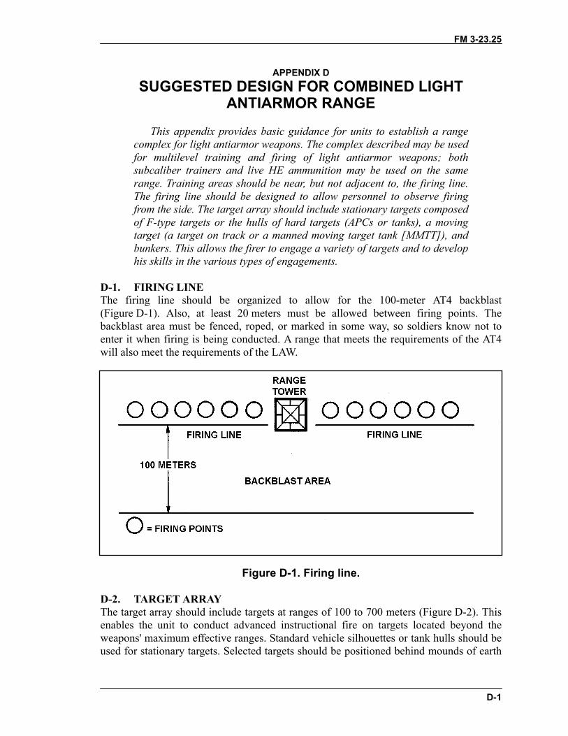
FM 3-23.25
D-1
APPENDIX DSUGGESTED DESIGN FOR COMBINED LIGHT
ANTIARMOR RANGE
This appendix provides basic guidance for units to establish a rangecomplex for light antiarmor weapons. The complex described may be usedfor multilevel training and firing of light antiarmor weapons; bothsubcaliber trainers and live HE ammunition may be used on the samerange. Training areas should be near, but not adjacent to, the firing line.The firing line should be designed to allow personnel to observe firingfrom the side. The target array should include stationary targets composedof F-type targets or the hulls of hard targets (APCs or tanks), a movingtarget (a target on track or a manned moving target tank [MMTT]), andbunkers. This allows the firer to engage a variety of targets and to develophis skills in the various types of engagements.
D-1. FIRING LINEThe firing line should be organized to allow for the 100-meter AT4 backblast(Figure D-1). Also, at least 20 meters must be allowed between firing points. Thebackblast area must be fenced, roped, or marked in some way, so soldiers know not toenter it when firing is being conducted. A range that meets the requirements of the AT4will also meet the requirements of the LAW.
Figure D-1. Firing line.
D-2. TARGET ARRAYThe target array should include targets at ranges of 100 to 700 meters (Figure D-2). Thisenables the unit to conduct advanced instructional fire on targets located beyond theweapons' maximum effective ranges. Standard vehicle silhouettes or tank hulls should beused for stationary targets. Selected targets should be positioned behind mounds of earth
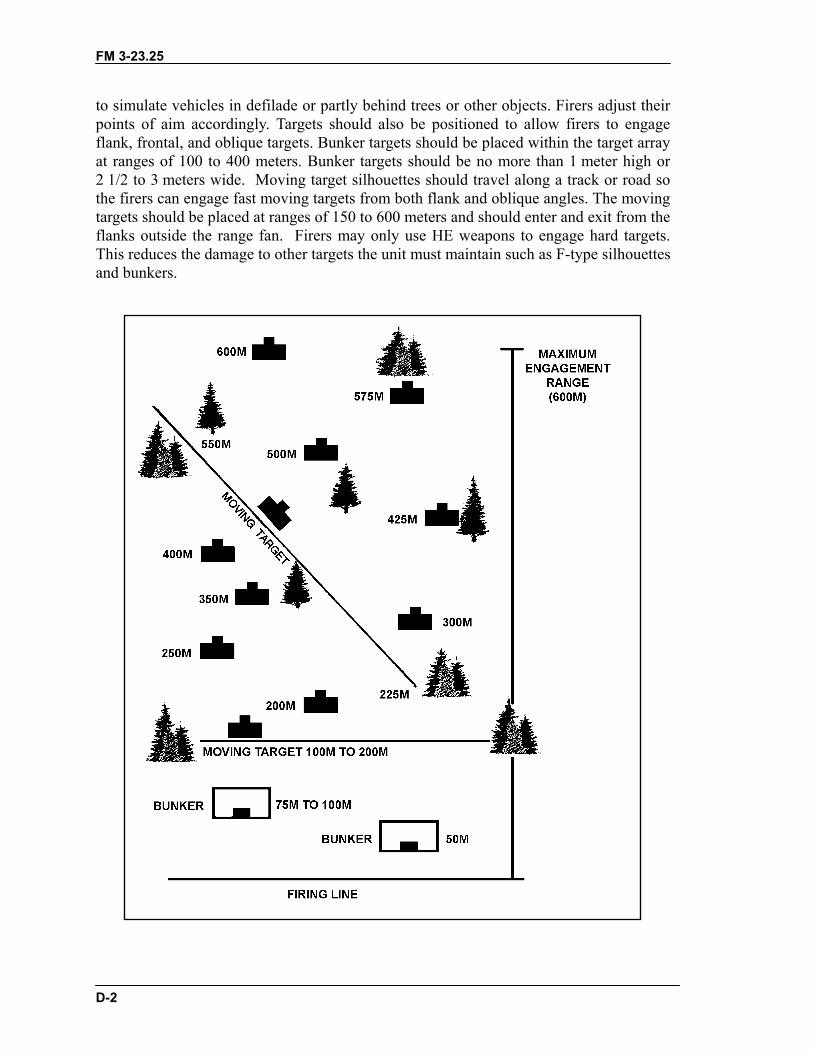
FM 3-23.25
D-2
to simulate vehicles in defilade or partly behind trees or other objects. Firers adjust theirpoints of aim accordingly. Targets should also be positioned to allow firers to engageflank, frontal, and oblique targets. Bunker targets should be placed within the target arrayat ranges of 100 to 400 meters. Bunker targets should be no more than 1 meter high or2 1/2 to 3 meters wide. Moving target silhouettes should travel along a track or road sothe firers can engage fast moving targets from both flank and oblique angles. The movingtargets should be placed at ranges of 150 to 600 meters and should enter and exit from theflanks outside the range fan. Firers may only use HE weapons to engage hard targets.This reduces the damage to other targets the unit must maintain such as F-type silhouettesand bunkers.

FM 3-23.25
D-3
Figure D-2. Target array.
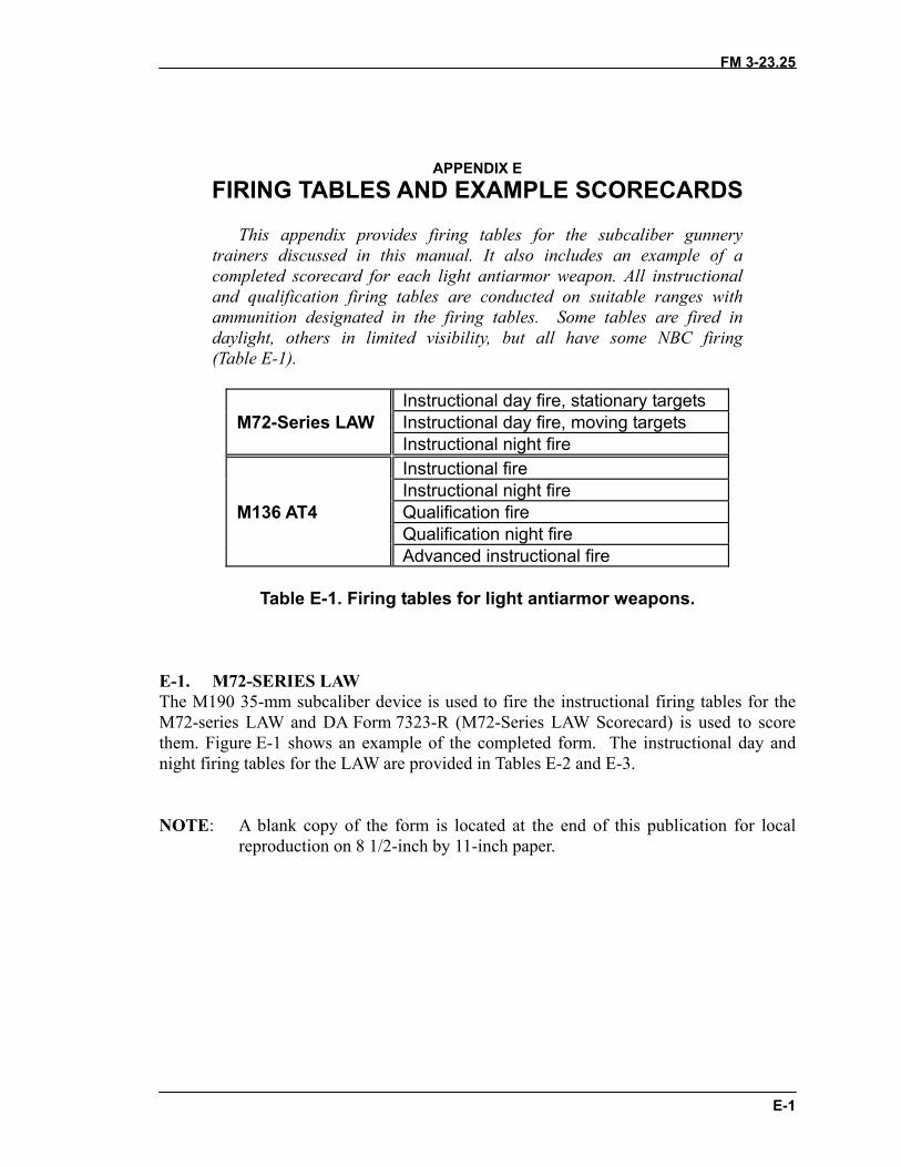
FM 3-23.25
E-1
APPENDIX EFIRING TABLES AND EXAMPLE SCORECARDS
This appendix provides firing tables for the subcaliber gunnerytrainers discussed in this manual. It also includes an example of acompleted scorecard for each light antiarmor weapon. All instructionaland qualification firing tables are conducted on suitable ranges withammunition designated in the firing tables. Some tables are fired indaylight, others in limited visibility, but all have some NBC firing(Table E-1).
Instructional day fire, stationary targetsM72-Series LAW Instructional day fire, moving targets
Instructional night fireInstructional fireInstructional night fire
M136 AT4 Qualification fireQualification night fireAdvanced instructional fire
Table E-1. Firing tables for light antiarmor weapons.
E-1. M72-SERIES LAWThe M190 35-mm subcaliber device is used to fire the instructional firing tables for theM72-series LAW and DA Form 7323-R (M72-Series LAW Scorecard) is used to scorethem. Figure E-1 shows an example of the completed form. The instructional day andnight firing tables for the LAW are provided in Tables E-2 and E-3.
NOTE: A blank copy of the form is located at the end of this publication for localreproduction on 8 1/2-inch by 11-inch paper.
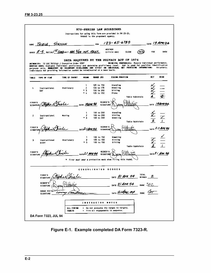
FM 3-23.25
E-2
Figure E-1. Example completed DA Form 7323-R.
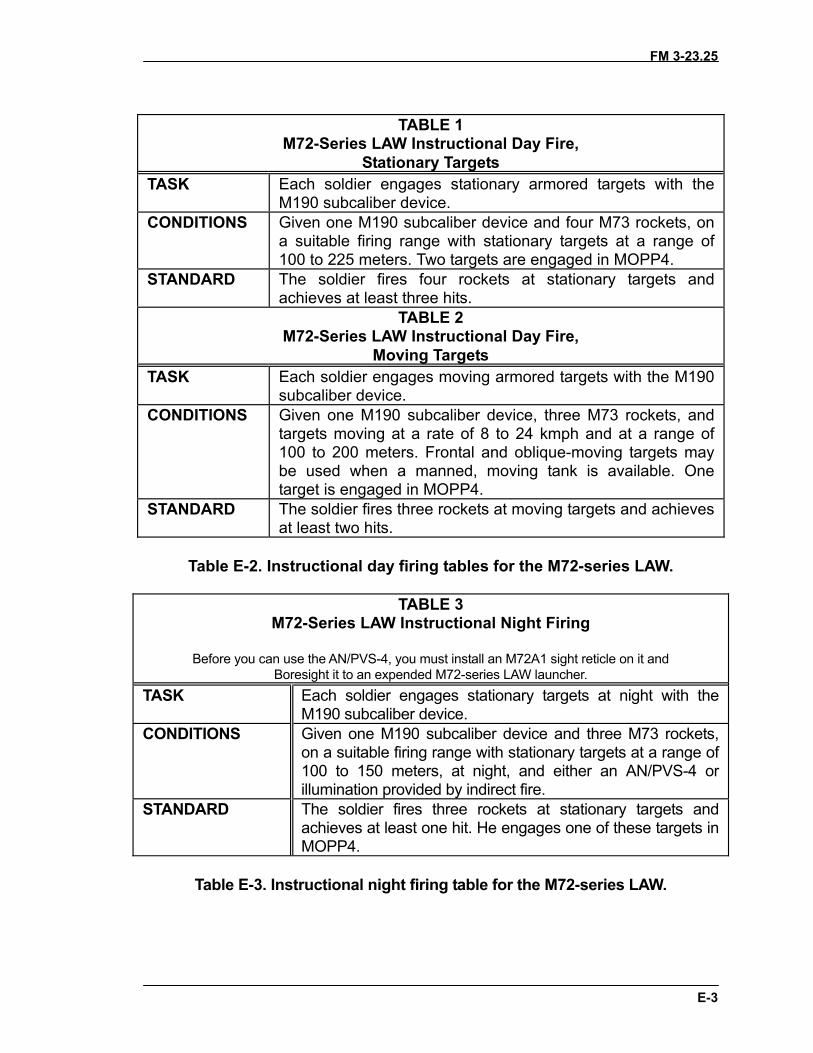
FM 3-23.25
E-3
TABLE 1M72-Series LAW Instructional Day Fire,
Stationary TargetsTASK Each soldier engages stationary armored targets with the
M190 subcaliber device.CONDITIONS Given one M190 subcaliber device and four M73 rockets, on
a suitable firing range with stationary targets at a range of100 to 225 meters. Two targets are engaged in MOPP4.
STANDARD The soldier fires four rockets at stationary targets andachieves at least three hits.
TABLE 2M72-Series LAW Instructional Day Fire,
Moving TargetsTASK Each soldier engages moving armored targets with the M190
subcaliber device.CONDITIONS Given one M190 subcaliber device, three M73 rockets, and
targets moving at a rate of 8 to 24 kmph and at a range of100 to 200 meters. Frontal and oblique-moving targets maybe used when a manned, moving tank is available. Onetarget is engaged in MOPP4.
STANDARD The soldier fires three rockets at moving targets and achievesat least two hits.
Table E-2. Instructional day firing tables for the M72-series LAW.
TABLE 3M72-Series LAW Instructional Night Firing
Before you can use the AN/PVS-4, you must install an M72A1 sight reticle on it andBoresight it to an expended M72-series LAW launcher.
TASK Each soldier engages stationary targets at night with theM190 subcaliber device.
CONDITIONS Given one M190 subcaliber device and three M73 rockets,on a suitable firing range with stationary targets at a range of100 to 150 meters, at night, and either an AN/PVS-4 orillumination provided by indirect fire.
STANDARD The soldier fires three rockets at stationary targets andachieves at least one hit. He engages one of these targets inMOPP4.
Table E-3. Instructional night firing table for the M72-series LAW.
FM 3-23.25
E-4
E-2. M136 AT4The M287 9-mm tracer bullet trainer is used to fire the instructional, qualification, andadvanced instructional firing tables for the M136 AT4 and DA Form 7324-R (M136 AT4Scorecard) is used to score them. A copy of this form is located at the end of this publicationfor local reproduction on 8 1/2-inch by 11-inch paper. Figure E-2 shows an example of thecompleted form; Tables E-4 through E-6, on pages E-7, E-8, and E-9, provide theinstructional, qualification, and advanced instructional firing tables for the AT4. The lattermust be fired on a separate, more specialized range.
E-3. NIGHT COURSE OF FIRE TABLES AND QUALIFICATION FOR M136AT4Each soldier is given a PMI before the instructional and qualification tables are fired. Oncethe soldier completes Table I and III (day tables), he is given additional instruction on the useof the aided vision devices for the night operations.
a. Qualification Tables for the M287 Tracer Trainer.• Table I (Instructional Day). This scenario consists of 12 targets from 100 to
300 meters. The standard to proceed to the next table is 6 out of 12 targetssuccessfully engaged.
• Table II (Instructional Night). This scenario consists of 8 targets from 100 to300 meters. The standard to proceed to the next table is 6 out of 12 targetssuccessfully engaged at night.
• Table III (Qualification Day). This scenario consists of 8 targets from 100 to300 meters. The standard to proceed to the next table is 6 out of 8 targetssuccessfully engaged.
• Table IV (Qualification Night). This scenario consists of 8 targets from 100 to300 meters (same as Table III, but conducted at night). The standard to proceedto the advanced firing tables is 6 out of 8 targets successfully engaged.
NOTES: 1. In Table IV, eight engagements are proposed as opposed to the current sixengagements.2. All references to the M136 launcher and cartridge refer to the M287 9-mmtracer bullet training device.
b. Ammunition Requirements for Night Training Strategy. The current STRACammunition allocation and course of fire is compared with the proposed night trainingstrategy in Table E-7 on page E-9. The current STRAC table stipulates that 120 rounds of 9-mm tracer ammunition is authorized to each squad for additional squad members to fireTables I and IV.
c. Day Standards. Commanders are able to achieve the current day standard at nightwith the M136 AT4 through the use of training strategy within this field manual. A gunnerwho is qualified on the day standard and has executed preliminary marksmanship trainingwith the appropriate night vision device can achieve the current day standard at night.During testing, gunners had no problem engaging targets out to 300 meters. Table E-8, onpage E-9, shows the day standard and is also the proposed night standard.
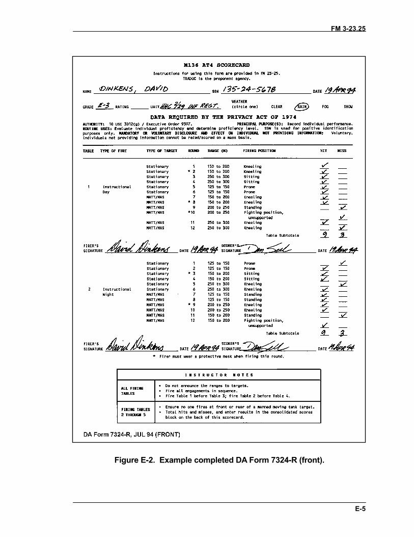
FM 3-23.25
E-5
•
Figure E-2. Example completed DA Form 7324-R (front).
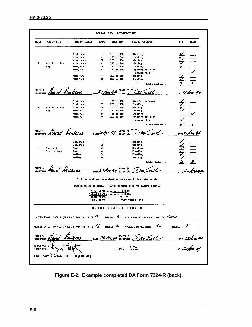
FM 3-23.25
E-6
Figure E-2. Example completed DA Form 7324-R (back).
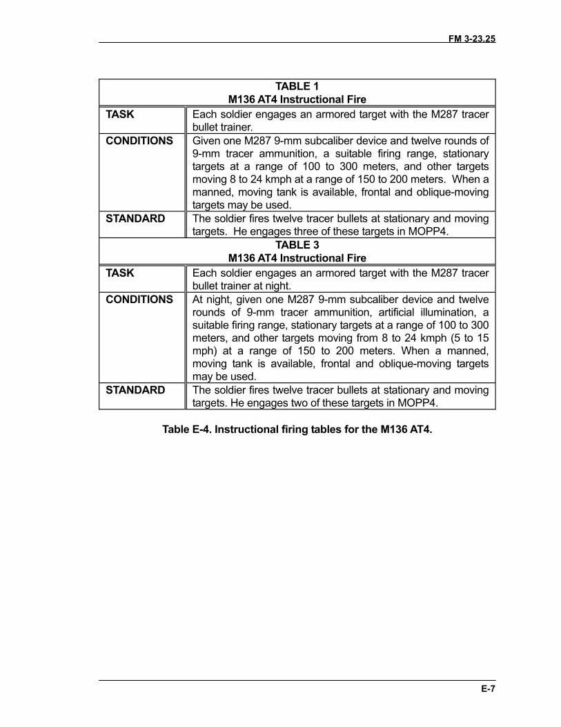
FM 3-23.25
E-7
TABLE 1M136 AT4 Instructional Fire
TASK Each soldier engages an armored target with the M287 tracerbullet trainer.
CONDITIONS Given one M287 9-mm subcaliber device and twelve rounds of9-mm tracer ammunition, a suitable firing range, stationarytargets at a range of 100 to 300 meters, and other targetsmoving 8 to 24 kmph at a range of 150 to 200 meters. When amanned, moving tank is available, frontal and oblique-movingtargets may be used.
STANDARD The soldier fires twelve tracer bullets at stationary and movingtargets. He engages three of these targets in MOPP4.
TABLE 3M136 AT4 Instructional Fire
TASK Each soldier engages an armored target with the M287 tracerbullet trainer at night.
CONDITIONS At night, given one M287 9-mm subcaliber device and twelverounds of 9-mm tracer ammunition, artificial illumination, asuitable firing range, stationary targets at a range of 100 to 300meters, and other targets moving from 8 to 24 kmph (5 to 15mph) at a range of 150 to 200 meters. When a manned,moving tank is available, frontal and oblique-moving targetsmay be used.
STANDARD The soldier fires twelve tracer bullets at stationary and movingtargets. He engages two of these targets in MOPP4.
Table E-4. Instructional firing tables for the M136 AT4.
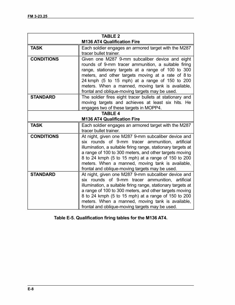
FM 3-23.25
E-8
TABLE 2M136 AT4 Qualification Fire
TASK Each soldier engages an armored target with the M287tracer bullet trainer.
CONDITIONS Given one M287 9-mm subcaliber device and eightrounds of 9-mm tracer ammunition, a suitable firingrange, stationary targets at a range of 100 to 300meters, and other targets moving at a rate of 8 to24 kmph (5 to 15 mph) at a range of 150 to 200meters. When a manned, moving tank is available,frontal and oblique-moving targets may be used.
STANDARD The soldier fires eight tracer bullets at stationary andmoving targets and achieves at least six hits. Heengages two of these targets in MOPP4.
TABLE 4M136 AT4 Qualification Fire
TASK Each soldier engages an armored target with the M287tracer bullet trainer.
CONDITIONS At night, given one M287 9-mm subcaliber device andsix rounds of 9-mm tracer ammunition, artificialillumination, a suitable firing range, stationary targets ata range of 100 to 300 meters, and other targets moving8 to 24 kmph (5 to 15 mph) at a range of 150 to 200meters. When a manned, moving tank is available,frontal and oblique-moving targets may be used.
STANDARD At night, given one M287 9-mm subcaliber device andsix rounds of 9-mm tracer ammunition, artificialillumination, a suitable firing range, stationary targets ata range of 100 to 300 meters, and other targets moving8 to 24 kmph (5 to 15 mph) at a range of 150 to 200meters. When a manned, moving tank is available,frontal and oblique-moving targets may be used.
Table E-5. Qualification firing tables for the M136 AT4.
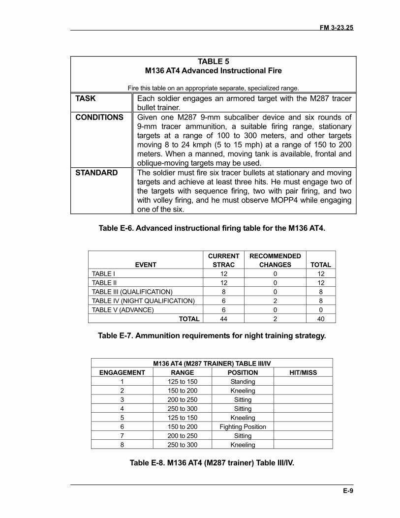
FM 3-23.25
E-9
TABLE 5M136 AT4 Advanced Instructional Fire
Fire this table on an appropriate separate, specialized range.TASK Each soldier engages an armored target with the M287 tracer
bullet trainer.CONDITIONS Given one M287 9-mm subcaliber device and six rounds of
9-mm tracer ammunition, a suitable firing range, stationarytargets at a range of 100 to 300 meters, and other targetsmoving 8 to 24 kmph (5 to 15 mph) at a range of 150 to 200meters. When a manned, moving tank is available, frontal andoblique-moving targets may be used.
STANDARD The soldier must fire six tracer bullets at stationary and movingtargets and achieve at least three hits. He must engage two ofthe targets with sequence firing, two with pair firing, and twowith volley firing, and he must observe MOPP4 while engagingone of the six.
Table E-6. Advanced instructional firing table for the M136 AT4.
EVENTCURRENT
STRACRECOMMENDED
CHANGES TOTALTABLE I 12 0 12TABLE II 12 0 12TABLE III (QUALIFICATION) 8 0 8TABLE IV (NIGHT QUALIFICATION) 6 2 8TABLE V (ADVANCE) 6 0 0
TOTAL 44 2 40
Table E-7. Ammunition requirements for night training strategy.
M136 AT4 (M287 TRAINER) TABLE III/IVENGAGEMENT RANGE POSITION HIT/MISS
1 125 to 150 Standing2 150 to 200 Kneeling3 200 to 250 Sitting4 250 to 300 Sitting5 125 to 150 Kneeling6 150 to 200 Fighting Position7 200 to 250 Sitting8 250 to 300 Kneeling
Table E-8. M136 AT4 (M287 trainer) Table III/IV.
FM 3-23.25
APPENDIX F INFRARED LASER AIMING DEVICES
The newest infrared laser pointers increase the night firing accuracy
of infantry weapons. The new family of weapon mounts (some fielded with the thermal weapon sight) and helmet brackets are more stable and reliable for continued accurate firing under field conditions. Their effectiveness is limited by the capability of the image-intensifying (I2) sight with which they are used. Normally this is a night vision goggle or monocular, with or without the 3X magnifier. Again, they primarily enhance the gunner’s ability to align his sights on the target, but usually have dramatic affect on his firing positions and scanning technique. Unlike I2 sights mounted on the weapon, the gunner can somewhat reduce the adverse effects of muzzle flash by rising up higher off the sight with his helmet-mounted goggle or monocular. With the AN/PEQ-2A, the range of these devices is greatly improved, allowing great effectiveness for crew-served weapons out to 2,200 meters. However, trainers and leaders must adopt new safety procedures to ensure these lasers, which are not safe for the eyes, are treated like loaded weapons any time the batteries are issued. Finally, the bore light is also effective to boresight these pointers. Generally weapons do not require zeroing with live ammunition to confirm alignment after soldiers and leaders are qualified in the boresighting techniques. The AT4 cannot be conventionally boresighed, therefore a sight alignment method is used to zero the aided vision device.
F-1. AN/PAQ-4C, AIMING LIGHT The AN/PAQ-4C aiming light (Figure F-1) projects an infrared laser beam, which cannot be seen with the eye but can be seen with night vision devices. This aiming light works with the AN/PVS-7B/C/D-series goggles and AN/PVS-14. The AN/PAQ-4C mounts on various weapons with mounting brackets and adapters. a. Technical Data. The following technical data apply to the AN/PAQ-4C: Optics: 100% parallax free, anti-reflective coated lens system
Length (sight): 14 centimeters (5.5 inches) Weight: 164 grams (5.78 ounces) Height: 3 centimeters (1.2 inches) Width: 6.5 centimeters (2.5 inches) Ranged: Beyond 600 meters. (Actual range depends on light level and night vision device used for observation.)
Battery life: 100-hour operating (ON) time for AA batteries in temperatures above 0 degrees Centigrade (32 degrees Fahrenheit); 36 hours for temperatures below 0 degrees Centigrade (32 degrees Fahrenheit)
F-1
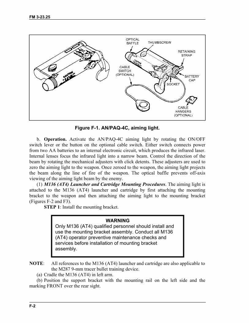
FM 3-23.25
Figure F-1. AN/PAQ-4C, aiming light. b. Operation. Activate the AN/PAQ-4C aiming light by rotating the ON/OFF switch lever or the button on the optional cable switch. Either switch connects power from two AA batteries to an internal electronic circuit, which produces the infrared laser. Internal lenses focus the infrared light into a narrow beam. Control the direction of the beam by rotating the mechanical adjusters with click detents. These adjusters are used to zero the aiming light to the weapon. Once zeroed to the weapon, the aiming light projects the beam along the line of fire of the weapon. The optical baffle prevents off-axis viewing of the aiming light beam by the enemy. (1) M136 (AT4) Launcher and Cartridge Mounting Procedures. The aiming light is attached to the M136 (AT4) launcher and cartridge by first attaching the mounting bracket to the weapon and then attaching the aiming light to the mounting bracket (Figures F-2 and F3). STEP 1: Install the mounting bracket. NOTE: All references to the M136 (AT4) launcher and cartridge are also applicable to
the M287 9-mm tracer bullet training device.
WARNING Only M136 (AT4) qualified personnel should install and use the mounting bracket assembly. Conduct all M136 (AT4) operator preventive maintenance checks and services before installation of mounting bracket assembly.
(a) Cradle the M136 (AT4) in left arm. (b) Position the support bracket with the mounting rail on the left side and the marking FRONT over the rear sight.
F-2
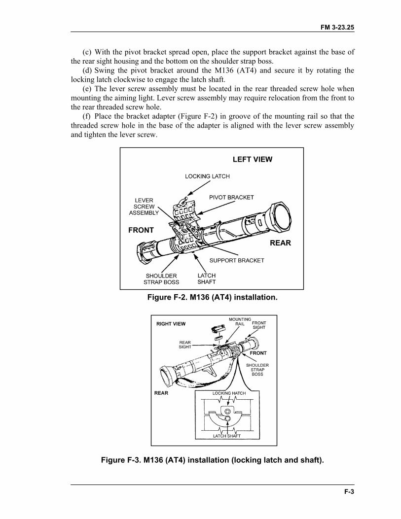
FM 3-23.25
(c) With the pivot bracket spread open, place the support bracket against the base of the rear sight housing and the bottom on the shoulder strap boss. (d) Swing the pivot bracket around the M136 (AT4) and secure it by rotating the locking latch clockwise to engage the latch shaft. (e) The lever screw assembly must be located in the rear threaded screw hole when mounting the aiming light. Lever screw assembly may require relocation from the front to the rear threaded screw hole. (f) Place the bracket adapter (Figure F-2) in groove of the mounting rail so that the threaded screw hole in the base of the adapter is aligned with the lever screw assembly and tighten the lever screw.
Figure F-2. M136 (AT4) installation.
Figure F-3. M136 (AT4) installation (locking latch and shaft).
F-3
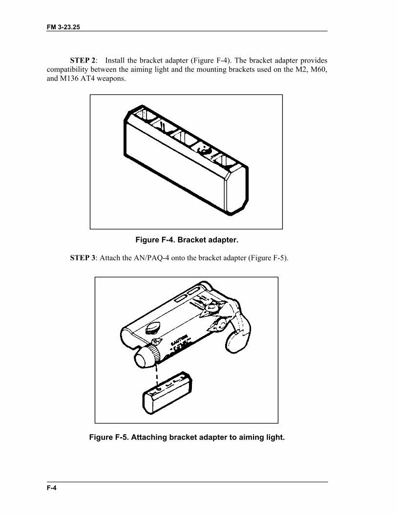
FM 3-23.25
STEP 2: Install the bracket adapter (Figure F-4). The bracket adapter provides compatibility between the aiming light and the mounting brackets used on the M2, M60, and M136 AT4 weapons.
Figure F-4. Bracket adapter. STEP 3: Attach the AN/PAQ-4 onto the bracket adapter (Figure F-5).
Figure F-5. Attaching bracket adapter to aiming light.
F-4
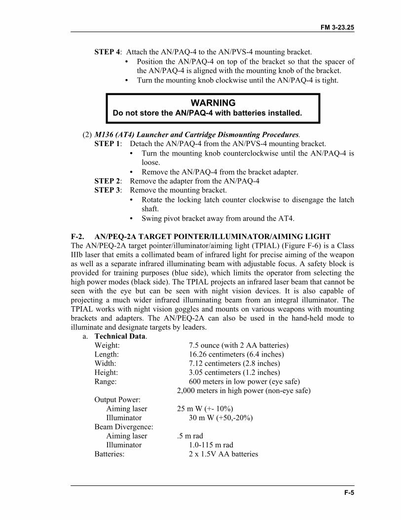
FM 3-23.25
STEP 4: Attach the AN/PAQ-4 to the AN/PVS-4 mounting bracket. • Position the AN/PAQ-4 on top of the bracket so that the spacer of
the AN/PAQ-4 is aligned with the mounting knob of the bracket. • Turn the mounting knob clockwise until the AN/PAQ-4 is tight.
WARNING Do not store the AN/PAQ-4 with batteries installed.
(2) M136 (AT4) Launcher and Cartridge Dismounting Procedures. STEP 1: Detach the AN/PAQ-4 from the AN/PVS-4 mounting bracket.
• Turn the mounting knob counterclockwise until the AN/PAQ-4 is loose.
• Remove the AN/PAQ-4 from the bracket adapter. STEP 2: Remove the adapter from the AN/PAQ-4 STEP 3: Remove the mounting bracket.
• Rotate the locking latch counter clockwise to disengage the latch shaft.
• Swing pivot bracket away from around the AT4. F-2. AN/PEQ-2A TARGET POINTER/ILLUMINATOR/AIMING LIGHT The AN/PEQ-2A target pointer/illuminator/aiming light (TPIAL) (Figure F-6) is a Class IIIb laser that emits a collimated beam of infrared light for precise aiming of the weapon as well as a separate infrared illuminating beam with adjustable focus. A safety block is provided for training purposes (blue side), which limits the operator from selecting the high power modes (black side). The TPIAL projects an infrared laser beam that cannot be seen with the eye but can be seen with night vision devices. It is also capable of projecting a much wider infrared illuminating beam from an integral illuminator. The TPIAL works with night vision goggles and mounts on various weapons with mounting brackets and adapters. The AN/PEQ-2A can also be used in the hand-held mode to illuminate and designate targets by leaders. a. Technical Data. Weight: 7.5 ounce (with 2 AA batteries) Length: 16.26 centimeters (6.4 inches) Width: 7.12 centimeters (2.8 inches) Height: 3.05 centimeters (1.2 inches) Range: 600 meters in low power (eye safe) 2,000 meters in high power (non-eye safe) Output Power: Aiming laser 25 m W (+- 10%) Illuminator 30 m W (+50,-20%) Beam Divergence: Aiming laser .5 m rad Illuminator 1.0-115 m rad Batteries: 2 x 1.5V AA batteries
F-5
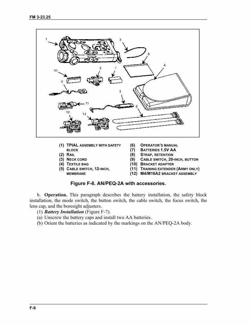
FM 3-23.25
(1) TPIAL ASSEMBLY WITH SAFETY (6) OPERATOR’S MANUAL BLOCK (7) BATTERIES 1.5V AA (2) RAIL (8) STRAP, RETENTION (3) NECK CORD (9) CABLE SWITCH, 20-INCH, BUTTON (4) TEXTILE BAG (10) BRACKET ADAPTER (5) CABLE SWITCH, 12-INCH, (11) TRAINING EXTENDER (ARMY ONLY) MEMBRANE (12) M4/M16A2 BRACKET ASSEMBLY
Figure F-6. AN/PEQ-2A with accessories.
b. Operation. This paragraph describes the battery installation, the safety block installation, the mode switch, the button switch, the cable switch, the focus switch, the lens cap, and the boresight adjusters. (1) Battery Installation (Figure F-7). (a) Unscrew the battery caps and install two AA batteries. (b) Orient the batteries as indicated by the markings on the AN/PEQ-2A body.
F-6

FM 3-23.25
Figure F-7. AN/PEQ-2A battery installation. (2) Safety Block Installation (Figure F-8). The safety block installed in the training mode (blue side up) prevents the operator from accessing the noneye safe modes (AIM HI, DUAL LO/HI, DUAL HI/HI). A .050 hex head Allen wrench is needed to unscrew the block from the body and reinstall it in the tactical mode (black side up).
Figure F-8. Safety block installation. (3) Mode Selector. The mode selector is used to set the mode in which the AN/PEQ-2A operates when the cable switch button or push button are depressed. The mode selector has six positions (Table F-1).
F-7
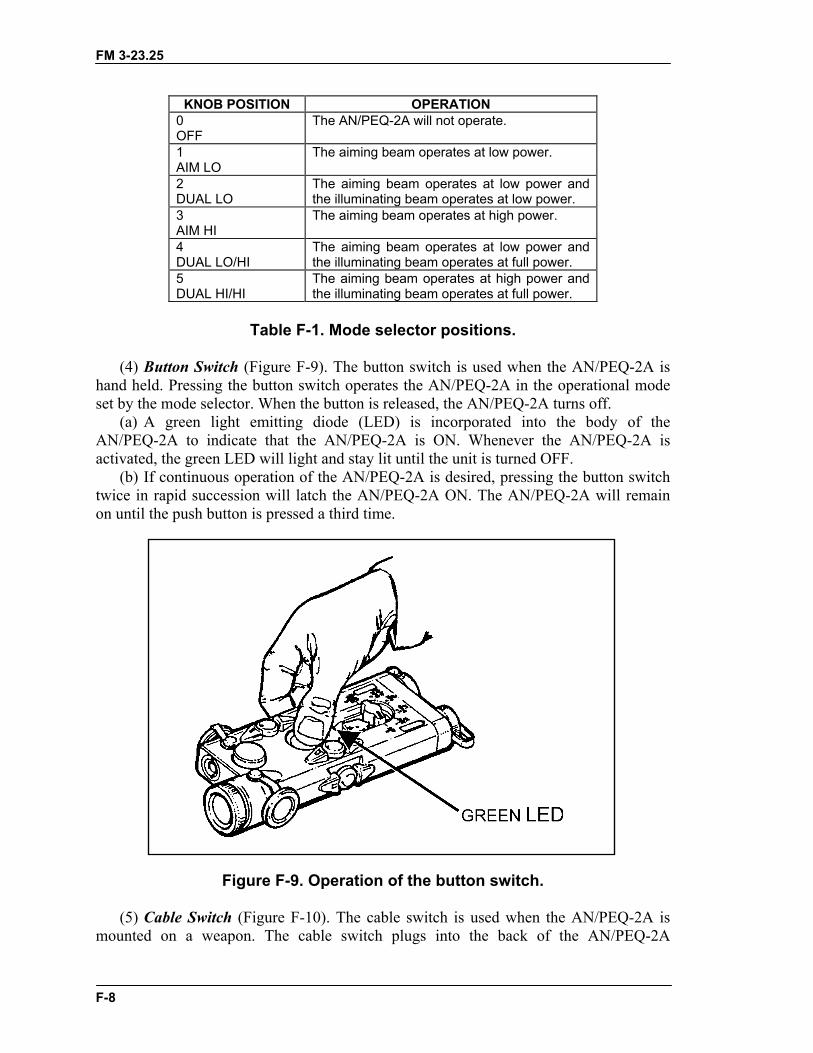
FM 3-23.25
KNOB POSITION OPERATION 0 OFF
The AN/PEQ-2A will not operate.
1 AIM LO
The aiming beam operates at low power.
2 DUAL LO
The aiming beam operates at low power and the illuminating beam operates at low power.
3 AIM HI
The aiming beam operates at high power.
4 DUAL LO/HI
The aiming beam operates at low power and the illuminating beam operates at full power.
5 DUAL HI/HI
The aiming beam operates at high power and the illuminating beam operates at full power.
Table F-1. Mode selector positions.
(4) Button Switch (Figure F-9). The button switch is used when the AN/PEQ-2A is hand held. Pressing the button switch operates the AN/PEQ-2A in the operational mode set by the mode selector. When the button is released, the AN/PEQ-2A turns off. (a) A green light emitting diode (LED) is incorporated into the body of the AN/PEQ-2A to indicate that the AN/PEQ-2A is ON. Whenever the AN/PEQ-2A is activated, the green LED will light and stay lit until the unit is turned OFF. (b) If continuous operation of the AN/PEQ-2A is desired, pressing the button switch twice in rapid succession will latch the AN/PEQ-2A ON. The AN/PEQ-2A will remain on until the push button is pressed a third time.
Figure F-9. Operation of the button switch. (5) Cable Switch (Figure F-10). The cable switch is used when the AN/PEQ-2A is mounted on a weapon. The cable switch plugs into the back of the AN/PEQ-2A
F-8
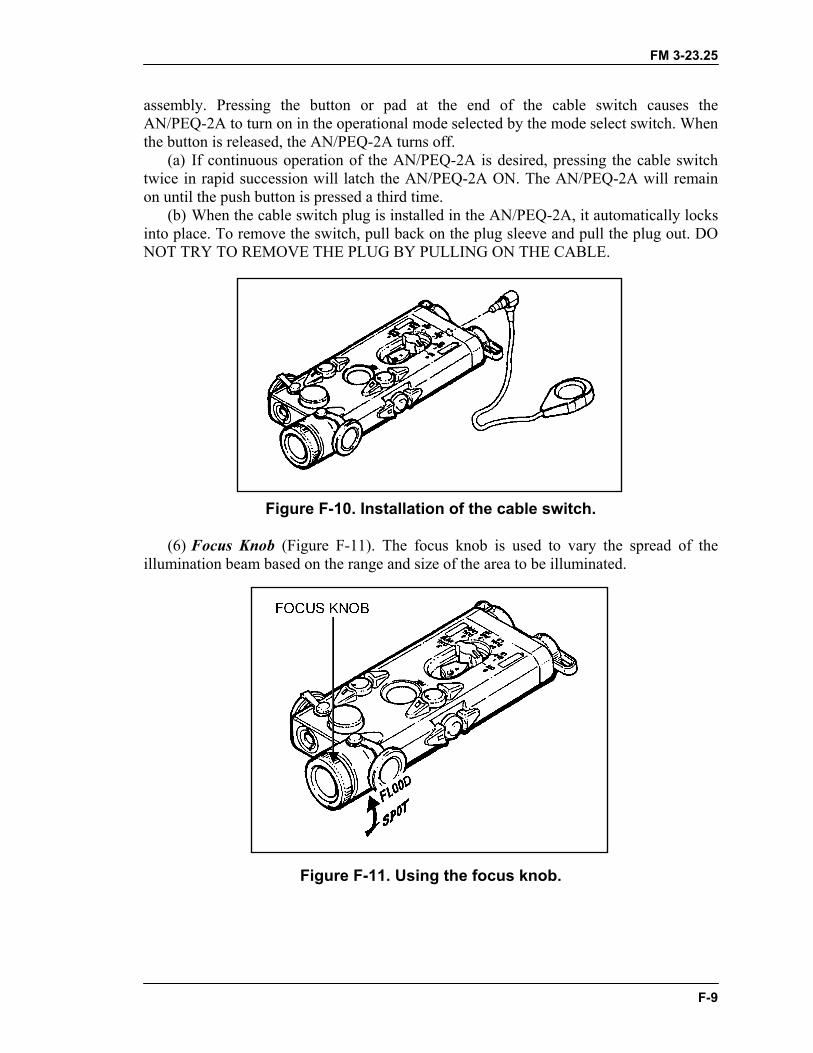
FM 3-23.25
assembly. Pressing the button or pad at the end of the cable switch causes the AN/PEQ-2A to turn on in the operational mode selected by the mode select switch. When the button is released, the AN/PEQ-2A turns off. (a) If continuous operation of the AN/PEQ-2A is desired, pressing the cable switch twice in rapid succession will latch the AN/PEQ-2A ON. The AN/PEQ-2A will remain on until the push button is pressed a third time. (b) When the cable switch plug is installed in the AN/PEQ-2A, it automatically locks into place. To remove the switch, pull back on the plug sleeve and pull the plug out. DO NOT TRY TO REMOVE THE PLUG BY PULLING ON THE CABLE.
Figure F-10. Installation of the cable switch. (6) Focus Knob (Figure F-11). The focus knob is used to vary the spread of the illumination beam based on the range and size of the area to be illuminated.
Figure F-11. Using the focus knob.
F-9
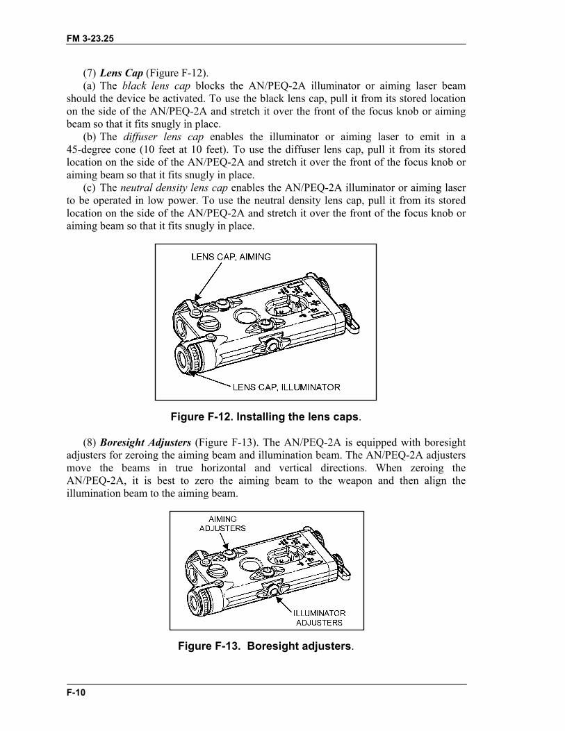
FM 3-23.25
(7) Lens Cap (Figure F-12). (a) The black lens cap blocks the AN/PEQ-2A illuminator or aiming laser beam should the device be activated. To use the black lens cap, pull it from its stored location on the side of the AN/PEQ-2A and stretch it over the front of the focus knob or aiming beam so that it fits snugly in place. (b) The diffuser lens cap enables the illuminator or aiming laser to emit in a 45-degree cone (10 feet at 10 feet). To use the diffuser lens cap, pull it from its stored location on the side of the AN/PEQ-2A and stretch it over the front of the focus knob or aiming beam so that it fits snugly in place. (c) The neutral density lens cap enables the AN/PEQ-2A illuminator or aiming laser to be operated in low power. To use the neutral density lens cap, pull it from its stored location on the side of the AN/PEQ-2A and stretch it over the front of the focus knob or aiming beam so that it fits snugly in place.
Figure F-12. Installing the lens caps. (8) Boresight Adjusters (Figure F-13). The AN/PEQ-2A is equipped with boresight adjusters for zeroing the aiming beam and illumination beam. The AN/PEQ-2A adjusters move the beams in true horizontal and vertical directions. When zeroing the AN/PEQ-2A, it is best to zero the aiming beam to the weapon and then align the illumination beam to the aiming beam.
Figure F-13. Boresight adjusters.
F-10
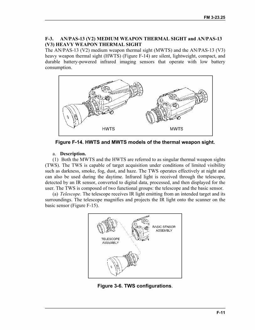
FM 3-23.25
F-3. AN/PAS-13 (V2) MEDIUM WEAPON THERMAL SIGHT and AN/PAS-13 (V3) HEAVY WEAPON THERMAL SIGHT The AN/PAS-13 (V2) medium weapon thermal sight (MWTS) and the AN/PAS-13 (V3) heavy weapon thermal sight (HWTS) (Figure F-14) are silent, lightweight, compact, and durable battery-powered infrared imaging sensors that operate with low battery consumption.
Figure F-14. HWTS and MWTS models of the thermal weapon sight. a. Description. (1) Both the MWTS and the HWTS are referred to as singular thermal weapon sights (TWS). The TWS is capable of target acquisition under conditions of limited visibility such as darkness, smoke, fog, dust, and haze. The TWS operates effectively at night and can also be used during the daytime. Infrared light is received through the telescope, detected by an IR sensor, converted to digital data, processed, and then displayed for the user. The TWS is composed of two functional groups: the telescope and the basic sensor. (a) Telescope. The telescope receives IR light emitting from an intended target and its surroundings. The telescope magnifies and projects the IR light onto the scanner on the basic sensor (Figure F-15).
Figure 3-6. TWS configurations.
F-11
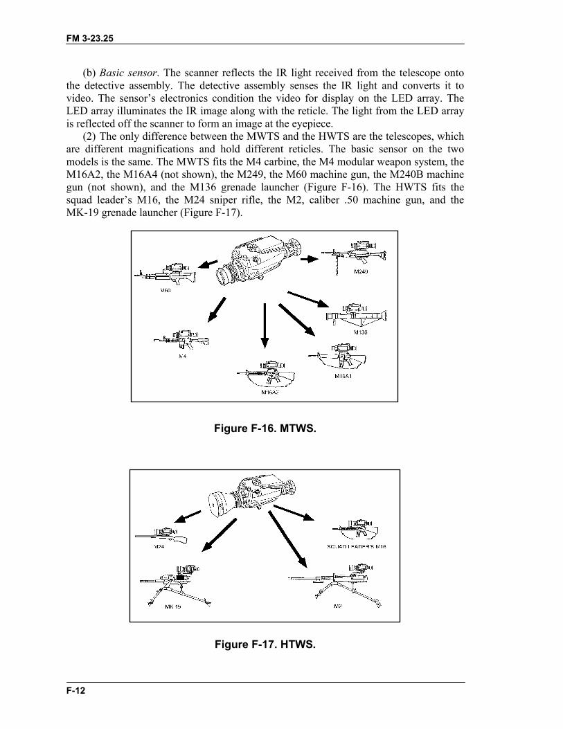
FM 3-23.25
(b) Basic sensor. The scanner reflects the IR light received from the telescope onto the detective assembly. The detective assembly senses the IR light and converts it to video. The sensor’s electronics condition the video for display on the LED array. The LED array illuminates the IR image along with the reticle. The light from the LED array is reflected off the scanner to form an image at the eyepiece. (2) The only difference between the MWTS and the HWTS are the telescopes, which are different magnifications and hold different reticles. The basic sensor on the two models is the same. The MWTS fits the M4 carbine, the M4 modular weapon system, the M16A2, the M16A4 (not shown), the M249, the M60 machine gun, the M240B machine gun (not shown), and the M136 grenade launcher (Figure F-16). The HWTS fits the squad leader’s M16, the M24 sniper rifle, the M2, caliber .50 machine gun, and the MK-19 grenade launcher (Figure F-17).
Figure F-16. MTWS.
Figure F-17. HTWS.
F-12

FM 3-23.25
b. Technical Data. MWTS HWTS Field of view (FOV): Narrow 9 degrees 3 degrees Wide 15 degrees 9 degrees Telescope magnification: Narrow FOV 3.3X 10X Wide FOV 2X 3.3X Length: 15.5 inches 18 inches Width: 6.25 inches 6.25 inches Height: 6.25 inches 6.25 inches Weight 4.1 pounds 4.5 pounds Power consumption: ON mode 12.0 watts 12.0 watts STANDBY mode 5.5 watts 5.5 watts Battery life: 71% STANDBY mode 10 hours 10 hours EMERGENCY mode 3.5 hours 3.5 hours c. Operation. (1) The TWS has three modes of operation: STANDBY, ON, and EMERGENCY. (a) STANDBY mode. When the system is first turned on, the TWS begins a cool down period of approximately two minutes. After the cool down period, the TWS enters the STANDBY mode. During the STANDBY mode, power is not applied to the scanner or display in order to extend the life of the battery. (b) ON mode. When the TWS is in the STANDBY mode and pressure is applied to the eyecup, the TWS switches to the ON mode, and a switch engages to provide power to the scanner and display. After a three-second delay, the system is fully operational. (c) EMERGENCY mode. When switched to the EMERGENCY mode, the TWS continuously applies power to the entire system. This allows the operator to bypass the three-second delay experienced when switching from the STANDBY to the ON mode. Since power is applied to the entire system while in the emergency mode, battery life is greatly reduced. (2) Controls and indicators are as shown in Figure 3-18. (a) The BRIGHTNESS CONTROL is a nine-position rotary switch with an off detent position (turned fully counterclockwise). The purpose is to turn the system on or off and adjust the brightness of the eyepiece display. (b) The CONTRAST CONTROL adjusts the contrast of the thermal image displayed on the raster. It has an automatic and a manual mode. (c) The FOCUS RING adjusts the telescope focus from 20 meters to infinity. It requires a manual adjustment and affects both the wide and narrow fields of view. (d) The FIELD OF VIEW RING is located on the telescope. It has a wide and a narrow field of view. The wide FOV is for using low magnification during target detection, and the narrow FOV is for using high magnification during recognition and engagement. (e) The RETICLE SELECT SWITCH selects one of the available reticles depending on the TWS model (medium or heavy). It must be held for two seconds to enable reticle
F-13
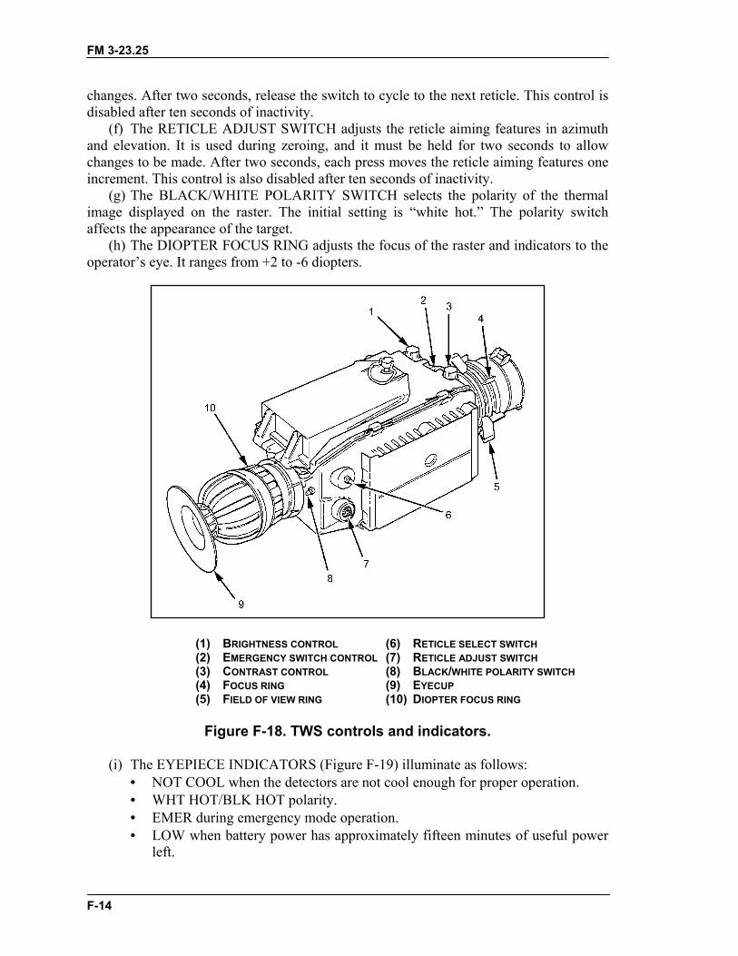
FM 3-23.25
changes. After two seconds, release the switch to cycle to the next reticle. This control is disabled after ten seconds of inactivity. (f) The RETICLE ADJUST SWITCH adjusts the reticle aiming features in azimuth and elevation. It is used during zeroing, and it must be held for two seconds to allow changes to be made. After two seconds, each press moves the reticle aiming features one increment. This control is also disabled after ten seconds of inactivity. (g) The BLACK/WHITE POLARITY SWITCH selects the polarity of the thermal image displayed on the raster. The initial setting is “white hot.” The polarity switch affects the appearance of the target. (h) The DIOPTER FOCUS RING adjusts the focus of the raster and indicators to the operator’s eye. It ranges from +2 to -6 diopters.
(1) BRIGHTNESS CONTROL (6) RETICLE SELECT SWITCH (2) EMERGENCY SWITCH CONTROL (7) RETICLE ADJUST SWITCH (3) CONTRAST CONTROL (8) BLACK/WHITE POLARITY SWITCH (4) FOCUS RING (9) EYECUP (5) FIELD OF VIEW RING (10) DIOPTER FOCUS RING
Figure F-18. TWS controls and indicators.
(i) The EYEPIECE INDICATORS (Figure F-19) illuminate as follows:
• NOT COOL when the detectors are not cool enough for proper operation. • WHT HOT/BLK HOT polarity. • EMER during emergency mode operation. • LOW when battery power has approximately fifteen minutes of useful power
left.
F-14
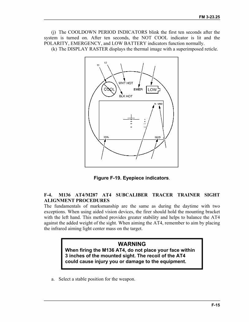
FM 3-23.25
(j) The COOLDOWN PERIOD INDICATORS blink the first ten seconds after the system is turned on. After ten seconds, the NOT COOL indicator is lit and the POLARITY, EMERGENCY, and LOW BATTERY indicators function normally. (k) The DISPLAY RASTER displays the thermal image with a superimposed reticle.
Figure F-19. Eyepiece indicators. F-4. M136 AT4/M287 AT4 SUBCALIBER TRACER TRAINER SIGHT ALIGNMENT PROCEDURES The fundamentals of marksmanship are the same as during the daytime with two exceptions. When using aided vision devices, the firer should hold the mounting bracket with the left hand. This method provides greater stability and helps to balance the AT4 against the added weight of the sight. When aiming the AT4, remember to aim by placing the infrared aiming light center mass on the target.
WARNING When firing the M136 AT4, do not place your face within 3 inches of the mounted sight. The recoil of the AT4 could cause injury you or damage to the equipment.
a. Select a stable position for the weapon.
F-15

FM 3-23.25
b. Open the M136 front and rear sight covers. During limited visibility conditions, the 7-millimeter peephole may be necessary for zeroing.
c. Set the rear sight for 200 meters and choose the appropriate scenario. (1) Place a 25 meter zero target with a predetermined offset at 10 meters and align the weapon’s fixed sight to coincide with the 4-centimeter aiming point of the zero target. (2) Select a suitable target at 200 meters and align the weapon’s fixed sight center mass of the target. d. Turn on the infrared aiming light. Use the AN/PVS-7B or AN/PVS-14 to observe the infrared aiming light (without moving the weapon). e. Adjust the infrared aiming light so that it coincides with the 2-centimeter offset aiming point of the 25-meter zero target. If the 200-meter method is used, adjust the aiming point of the mounted sight to coincide center mass on the 200-meter target. f. Repeat the procedure until the aiming light is sight aligned to the weapon by adjusting the controls on the AN/PAQ-4C. NOTE: Use the same procedures to conduct sight alignment of the AN/PEQ-2. g. Conduct a preventive maintenance inspection before the instructional and qualification tables are fired. Once the soldiers have completed Tables I and III (day tables), they receive additional instruction on the use of aided vision devices for night operations. (1) Table I (Instructional Day). This scenario consists of 12 targets from 100 to 300 meters. The standard to proceed to the next table is 6 out of 12 targets successfully engaged. (2) Table II (Instructional Night). This scenario consists of 12 targets from 100 to 300 meters. The standard to proceed to the next table is 6 out of 12 targets successfully engaged at night. (3) Table III (Qualification Day). This scenario consists of 10 targets from 100 to 300 meters. The standard to proceed to the next table is 8 out of 10 targets successfully engaged. (4) Table IV (Qualification Night). This scenario consists of 10 targets from 100 to 300 meters. The standard to proceed to the next table is 6 out of 10 targets successfully engaged. h. The night sustainment training strategy should be conducted over a one-day time frame and consists of the following: (1) Night Vision Goggles Familiarization Training. Soldiers receive instruction on the proper use and fit of night vision goggles, to include characteristics and capabilities, maintenance, and mounting procedures. (2) Infrared Aiming Light Familiarization Training. Soldiers boresight the weapon and aided vision device at a range of 10 meters. (3) Fundamentals of Firing (Body Position with Head Harness and NVD, Foxhole and Prone). Soldiers review and practice firing positions and fundamentals of marksmanship and any changes that may occur by use of the infrared aiming device. (4) Weapon and Equipment Precombat Inspection. The weapon and infrared aiming device is inspected and properly mounted. Inspect to ensure that the infrared aiming
F-16

FM 3-23.25
device is mounted securely to the mount and that the mount is tightly secured to the weapon. A review of clearing or misfire procedures is important. (5) Infrared Aiming Light Boresight to Weapon. Each soldier boresights the weapon and infrared aiming device at a range of 10 meters. If a bore light is not available, then zero the weapon and sight by using the specified zeroing procedure for that weapon/sight combination.
F-17

FM 3-23.25
Glossary-1
GLOSSARY
AC Active Component
ANCOC advanced noncommissioned officer course
AN/PVS Army Navy passive vision sight
ARTEP Army Training and Evaluation Program
backblast The backward blast created by igniting the propellant in a weapondesigned to be as recoilless as possible.
blast An explosive or violent detonation that produces a direct effect on itstarget in addition to radiant heat and overpressure at its point of origin.
BMP a type of non-US fighting vehicle built by the former Soviet Union
BNCOC basic noncommissioned officer course
BRDM a type of non-US scout car built by the former Soviet Union
BTR a type of non-US personnel carrier built by the former Soviet Union
C Centigrade
CS combat support
CSS combat service support
DA Department of the Army
DKIE decontamination kit individual equipment
DOD Department of Defense
DS direct support
F Fahrenheit
FHT field handling trainer
FM 3-23.25
Glossary-2
fps feet per second
FTX field training exercise
HE high-explosive
HEAT high-explosive antitank
HELLFIRE heliborne laser fire and forget (a missile system)
HMTS medium weapon thermal sight
HWTS heavy weapon thermal sight
IAW in accordance with
IET initial entry training
IR infrared
kmph kilometers per hour
LAW light antitank weapon
LED light emitting diode
METL mission-essential task list
MILES Multiple Integrated Laser Engagement System
mm millimeter(s)
MMTT manned moving target tank
MOPP mission-oriented protective posture
MOUT military operations on urbanized terrain
mph miles per hour
mps meters per second
MTP mission training plan
FM 3-23.25
Glossary-3
MWTS medium weapon thermal sight
NA not applicable
NATO North Atlantic Treaty Organization
NBC nuclear, biological, chemical
NCO noncommissioned officer
NSN national stock number
NVD night vision device
OIC officer in charge
overpressure increased atmospheric pressure (positive overpressure), followed by awave of decreased atmospheric pressure (negative overpressure),produced around the origin of an explosive or violent detonation
PLDC primary leadership development course
POI program of instruction
promethium a radioactive metallic element of the rare-earth group used toilluminate range markings on the front sight of the M72-series LAW
RC Reserve Component
RPG rocket-propelled grenade (non-US)
STX situational training exercise
SMCT soldier's manual of common tasks
SOP standing operating procedure
spall small fragment or chip
STP soldier training publication

FM 3-23.25
Glossary-4
STRAC standards in training commission
TOC tactical operations center
TP training-practice
TPIAL target pointer/illuminator/aiming light, AN/PEQ-2A
TRADOC (US Army) Training and Doctrine Command
trc track (as used in STRAC manual)
TRP target reference point
TSC training support center
TWS thermal weapon sight

FM 3-23.25
iii
PREFACE
This manual provides technical information, training techniques, and combattechniques of light antiarmor weapons. Intended users include leaders and designatedsoldiers who will use this information to successfully integrate light antiarmor weaponsinto combat operations. This manual discusses gunnery training and train-the-trainer.
The tactical positions shown in this manual were drawn to enhance the reader'sunderstanding of related subject material and do not necessarily represent the bestemployment option for that material.
Unless this publication states otherwise, masculine nouns and pronouns do not referexclusively to men.
The proponent of this publication is the United States Army Infantry School. Sendcomments and recommendations on DA Form 2028 (Recommended Changes toPublications and Blank Forms) directly to―
CommandantUS Army Infantry SchoolATTN: ATSH-IN-S3Fort Benning, GA [email protected]

FM 3-23.25
Index-1
INDEX
adjustment of fire, 2-11, 3-7, 3-8 (illus), 6-10
adjustment of sightsM72-series LAW, 2-8, 2-9 (illus)M136 AT4, 3-7, 3-8 (illus)
aiming procedures, 2-11, 4-2 to 4-6 (illus)
ambushes, antiarmor, 6-13, 6-14 (illus)
AN/PVS-4 nightsight, 2-9 to 2-12 (illus), 6-10
arming range, minimum, 2-2, 3-2, A-4
armored vehicledead space, 6-4 (illus)weaknesses, 6-2, 6-3 (illus)
armor-killer teams, 6-13
assistant trainers, B-12
AT4 (see M136 AT4)
backblast, 2-1, 2-13, 3-8, 3-11 to 3-13 (illus), 5-2 to 5-6 (illus), 6-10, 6-11, A-1 to A-3(illus), B-1, B-6, D-1 (illus)
buildingsengaging, 6-8, 6-9 (illus)firing from, 6-10
bunkers, engagement of, 6-9 (illus)
care and handling, 1-2, 2-5, 3-4
collective training, 7-1, 7-4
color codes, M136 AT4, 3-4 (illus)

FM 3-23.25
Index-2
combatrange, minimum, 2-2, 3-2, A-4techniques, 6-1
DA Form 7323-R (M72-Series LAW Scorecard), E-1, E-2 (illus)
DA Form 7324-R (M136 AT4 Scorecard), E-4, E-5 to E-6 (illus)
danger zones, A-1, A-2
dead space, armored vehicle, 6-3, 6-4 (illus)
defensive operations, 6-12, 6-14
effective range, maximum, 2-2, 3-2, 6-12, D-2
effects, weapon, 2-3, 3-2, 3-3 (illus), 6-9 (illus), 6-11
employment, 1-1, 2-3, 6-1, 6-4, 6-10 to 6-14 (illus)
enclosures, firing from, 6-11, A-2, A-3
engagement range, 2-2, 3-2maximum, D-2minimum, A-4
eye placement, 4-2 (illus)
field fortifications, engagement of, 6-9 (illus)
field-handling trainers, C-1 to C-5, C-7 M72-series LAW, B-1 (illus), B-2 (illus)M136 AT4, 3-4, 3-12, 4-6, B-6
firingfrom enclosures, 6-11, A-2, A-3limitations, A-2, A-3, A-4line, D-1positions (see appropriate weapon)range, suggested design for, D-1tables, 7-2, E-3, E-7, E-8techniques, 6-9 (illus)
force-on-force trainer, 7-4
FM 3-23.25
Index-3
fratricide avoidance, 1-2, 1-3, 2-5, 2-11, 2-13, 2-14, 3-11, 6-12, A-1 to A-4
front sight template, B-5 (illus)
fundamentals of marksmanship, 4-2 to 4-6 (illus)
Graphic Training Aid 7-2-5 (Sight Engagement Trainer, AT4), B-5 (illus)
gunnery training requirements, 7-1 to 7-3
IET (initial entry training), 7-1, 7-2
illumination, 6-10, E-3, E-7, E-8
individual training, 7-1 to 7-5
infantry fighting position, A-3
initial entry training (IET), 7-1 7-2
inspectionM72-series LAW, 2-5M136 AT4, 3-4
institutional training, 7-1 (illus)
kills, types of, 6-5
launcher, expendedM72-series LAW, B-1 (illus), B-2 (illus)M136 AT4, B-6
LAW (light antitank weapon see M72-series LAW)
limited visibility, 3-1, 6-1, 6-10, 6-13armored vehicle, 6-3, 6-4 (illus)firing tables, E-1, E-3, E-7, E-8
live fire, 1-2 (illus), 1-3, 2-15, 3-12, 3-13, 6-10, 7-2, B-1, B-10
FM 3-23.25
Index-4
M72A1 mounting bracket assembly, 2-10
M72-series LAW, 1-1 (illus), 2-1, 2-2 (illus), 2-12, 4-6employment, 1-1, 2-3, 4-3, 4-4 (illus), 6-1, 6-4, 6-10 to 6-14 (illus)firing
mechanism, 2-6 to 2-8 (illus)positions, 5-1 to 5-6 (illus)range, suggested design for, D-1tables, 7-2, E-3
misfire procedures, 1-2, 1-3, 2-14, 7-3, 7-5, C-6nightsight, 2-10operation and function, 2-12packaging, 2-4 (illus)rocket, 2-2, 2-3 (illus)safety, 2-5, 2-8, 2-11, 2-14, 2-15, A-2 (see also backblast and fratricide avoidance)safety mechanism, 2-6 (illus), 2-7 (illus)scorecard, E-1, E-2 (illus)sight
adjustment, 2-8, 2-9 (illus)picture, 4-3 to 4-5 (illus)
target engagement, 4-3 (illus), 4-4 (illus)technical data, 2-2training device, B-1, B-2 (illus)warhead, 2-3weapon effects, 2-3, 5-6, 6-8, 6-9 (illus)
M72-Series LAW Scorecard (DA Form 7323-R), E-1, E-2 (illus)
M136 AT4, 3-1 (illus)employment, 1-1, 4-4, 4-5 (illus), 6-1, 6-4, 6-10 to 6-14 (illus)firing
mechanism, 3-5 (illus)positions, 5-1 to 5-6 (illus), A-2range, suggested design for, D-1tables, 7-2, E-7
function, 3-5misfire procedures, 1-2, 1-3, 3-11 to 3-13 (illus), 7-3, 7-5, C-6operation, 3-1, 3-8 to 3-11 (illus), 4-6, 6-11 (illus)overpressure, 6-10packaging, 3-3 (illus)safety, 3-8, 3-12, 6-10, A-2 to A-3 (see also backblast and fratricide avoidance)safety mechanisms, 3-5 (illus), 3-6 (illus)scorecard, E-4, E-5 to E-6 (illus)sight
adjustment, 3-7, 3-8 (illus), 3-10 (illus)picture, 4-4 to 4-5 (illus)
FM 3-23.25
Index-5
target engagement, 4-4, 4-5 (illus)technical data, 3-2training devices, 3-4 (illus), B-6 (illus)warhead, 1-3, 3-2, A-4weapon effects, 3-2, 3-3 (illus), 5-6,
6-8, 6-9 (illus)
M136 AT4 Scorecard (DA Form 7324-R), E-4, E-5 to E-6 (illus)
M190 subcaliber launcher, 2-15, B-1 to B-5, E-2
M287 subcaliber tracer trainer, 3-13, B-6 (illus), B-12, E-7 to E-8
marksmanship, fundamentals of, 4-2 through 4-6 (illus)
maximum effective range, 2-2, 3-2, 6-12, D-2
maximum engagement range, 2-2, 3-2, D-2
methods of engagement, 6-5 to 6-7
METL (mission-essential task list), 7-4
MILES (multiple integrated laser-engagement system), 7-4 (illus)
minimum range, 2-2, 3-2, A-4
misfire procedures, 1-2, 1-3, 7-3, 7-5, C-6M72-series LAW, 2-14M136 AT4, 3-11 to 3-13 (illus)M190 subcaliber launcher, 2-15, B-5M287 9-mm subcaliber tracer trainer, 3-13, B-12
mission-essential task list (METL), 7-4
mission outlines, 7-4
multiple integrated laser-engagement system (MILES), 7-4 (illus)
NBC (nuclear, biological, chemical), 6-10nightsight (AN/PVS-4), 2-9 to 2-12 (illus), 6-10
NVDs (night vision devices), 2-9 to 2-12 (illus), 6-10

FM 3-23.25
Index-6
obstacles, 6-3, 6-13
offensive operations, 6-1, 6-12
operating temperatures, 1-3, 2-1, 2-5 (illus), A-1, A-4, B-8
operationsdefensive, 6-12, 6-14offensive, 6-1, 6-12
overhead fire, A-4
overpressure, 6-10
performance evaluations, C-1
POIs (programs of instruction), 7-1 (illus)
raids, 6-14
rangecard, 6-12design, D-1estimation, 6-1of fire, 2-2, 3-2, A-4safety, 2-14, A-3, B-5, B-12
reactive armor, 6-2, 6-3
rear area operations, 6-13
resources, 7-3, B-1
restrictive terrain, 6-13
roles of light antiarmor weapons, 6-12 to 6-14
safety, 2-14, A-2 (see also backblast and fratricide avoidance)decontamination procedures, 1-3destruction procedures, 1-2 firing from an enclosure (combat), 6-11, A-2,
A-3 limitations, A-2hearing protection, 3-8, 6-11, A-3infantry fighting position, A-2, A-3
FM 3-23.25
Index-7
M72-series LAW, 2-5, 2-8, 2-11, 2-14M136 AT4, 3-8, 3-11, 3-12M190 subcaliber launcher, 2-15, B-5M287 9-mm subcaliber tracer trainer, 3-13, B-10, B-12nightsight, 2-11range safety, 2-14, B-5, B-12training, A-1, B-1
scorecards, example completedM72-series LAW, E-2 (illus)M136 AT4, E-5 to E-6 (illus)
sector sketch, 6-1, 6-12
security teams, 6-13
sight alignment, 4-2 to 4-5 (illus), 4-6
sight engagement trainer, AT4, B-5 (illus)
sightsM72-series LAW, 2-8, 2-9 (illus)M136 AT4, 3-7 (illus), 3-8 (illus), 3-10 (illus)
skill retention, 7-2 (illus), 7-5
speed estimation, 6-1, 6-2 (illus)
stationary targets, 4-3 to 4-5 (illus)
STRAC (Standards in Training Commission), 7-2, 7-3 (illus)
sustainment training program, 7-2 (illus), 7-5
tactical employment, 1-1, 2-3, 6-1, 6-4, 6-10 to 6-14 (illus)
target array, D-2 (illus)
target engagement, 4-3 to 4-5 (illus), 6-1
target silhouette sheet, B-5 (illus)
targets, moving, 4-3 to 4-5 (illus), 6-2, 6-7 (illus)

FM 3-23.25
Index-8
technical dataM72-series LAW, 2-2M136 AT4, 3-2
techniques of fire, 6-1, 6-2 (illus)
temperature effects, 1-3, 2-5, A-4, B-2
terrain, restrictive, 6-13
tracer trainer, subcaliber (M287), 3-13, B-6, B-12
training, 7-1 (illus), B-1aid, graphic, B-5 (illus)collective, 7-1, 7-4exercises, 7-2, B-1facilities, D-1frequency, 7-3 (illus)individual, 7-1 to 7-5initial entry, 7-1institutional, 7-1 (illus)program, 7-1requirements, 7-2, 7-3 (illus)safety, 2-14, A-1sequence, 7-4strategy, 7-1unit, 7-2
training devicesexpended launchers, 1-3, 4-6, B-1, B-2 (illus), B-6, C-1, E-3field-handling trainers, 3-4, 3-12, 4-6, B-6force-on-force trainers, 7-4subcaliber trainers, 3-13, 6-10, B-1, B-6
Training Support Center (TSC), B-1
train-the-trainer, 7-4
TSC (Training Support Center), B-1
unit training, 7-2
Viper, 7-4
FM 3-23.25
Index-9
warhead (see appropriate weapon)
weapon effects, 6-2M72-series LAW, 2-3M136 AT4, 3-2 to 3-3 (illus)
weather conditions, 1-3, 2-5, A-4, B-2 (see also limited visibility)
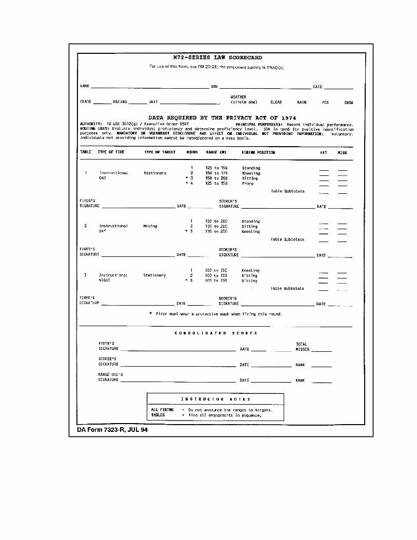
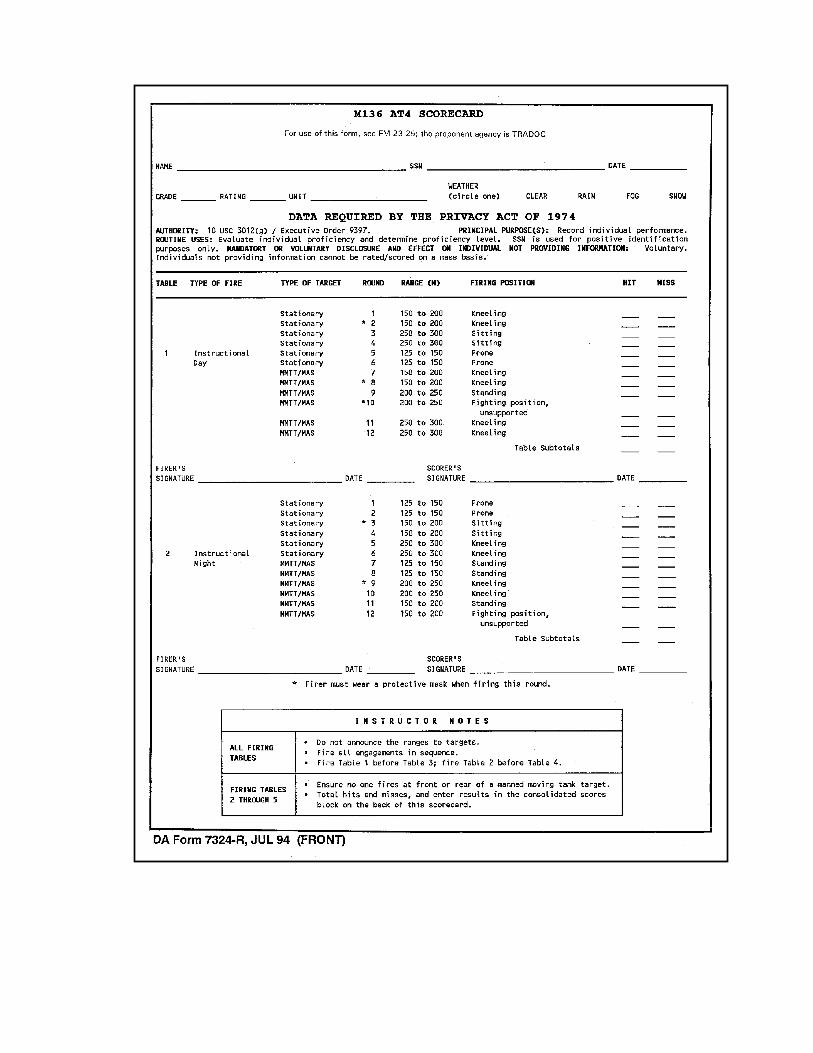
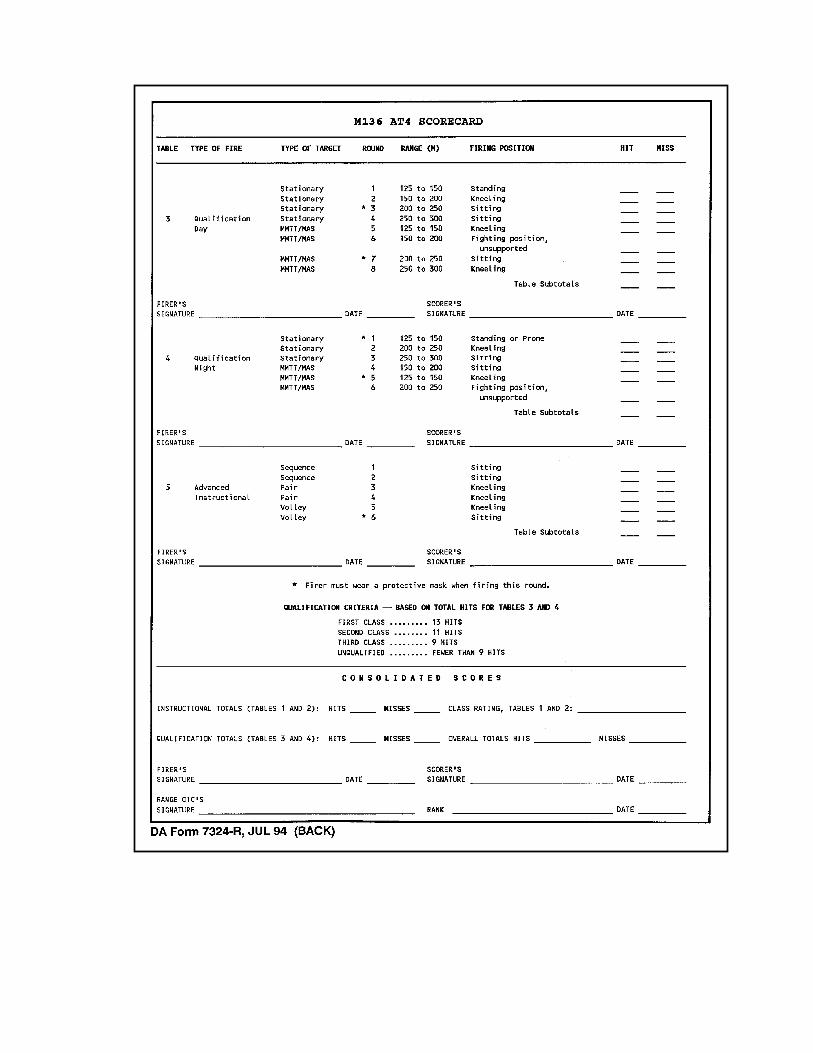
FM 3-23.25
References-1
REFERENCES
SOURCES USEDThese are the sources quoted or paraphrased in this manual.
TM 9-1055-886-12&P Operator and Unit Maintenance Manual for M287 9-MMTracer Bullet Training Device. 25 October 1989.
TM 9-1315-886-12 Operator's and Unit Maintenance Manual for Launcherand Cartridge, 84 Millimeter: M136 (AT4). 15 May 1990.
TM 9-1340-214-10 Operator's Manual for 66-MM Light Antitank Weapon(LAW) System M72A1, M72A2 with Coupler, M72A3,and Practice Rocket Launcher M190 with M73 PracticeRocket. 20 February 1992.
TM 11-5855-213-10 Operator's Manual for Night Vision Sight, Individual-Served Weapon AN/PVS-4. 1 February 1993.
TM 11-5855-213-23&P Unit and Direct Support Maintenance Manual for NightVision Sight, Individual-Served Weapon, AN/PVS-4. 1 June 1993.
DOCUMENTS NEEDEDThese documents must be available to the intended users of this publication.
DA Form 7323-R M72-Series LAW Scorecard. July 1994.
DA Form 7324-R M136 AT4 Scorecard. July 1994.
DA Pamphlet 350-38 Standards in Weapons Training. 3 July 1997.
*DOD 5100.76-M Physical Security of Sensitive Conventional Arms,Ammunition, and Explosives. 3 February 1983.
FM 7-7 The Mechanized Infantry Platoon and Squad (APC). 15 March 1985.
FM 7-7J The Mechanized Infantry Platoon and Squad (Bradley). 7 May 1993.
FM 7-8 The Infantry Platoon and Squad. 1 March 2001.
FM 25-101 Battle Focused Training. 30 September 1990.
FM 3-23.25
References-2
GTA 7-2-5 Sight Engagement Trainer, AT4 (Parts 1 and 2). 2 January 1990.
GTA 17-2-13 Armored Vehicle Recognition. 1 May 1987.
STP 7-11BCHM1-SM-TG Soldier’s Manual and Trainer’s Guide, Skill Level 1,CMF11, Infantry. 19 June 2000.
STP 7-11BCHM14-SM-TG Soldier's Manual and Trainer's Guide, Skill Level 2/3/4,MOS 11B, 11C, 11H, and 11M, Skill Levels 1/2/3/4. 19 June 2000.
STP 21-1-SMCT Soldier's Manual of Common Tasks, Skill Level 1. 1 October 1994.
TC 90-1 Training for Military Operations on Urbanized Terrain. 30 September 1993.
READINGS RECOMMENDEDThese readings contain relevant supplemental information.
AR 190-11 Physical Security of Arms, Ammunition, and Explosives. 30 September 1993.
AR 385-63 Policies and Procedures for Firing Ammunition forTraining, Target Practice, and Combat. 15 October 1983.
FM 3-5 NBC Decontamination. 28 July 2000.
FM 5-250 Explosives and Demolitions. 30 June 1998.
FM 20-3 Camouflage, Concealment, and Decoys. 30 August 1999.
FM 90-5 (HTF) Jungle Operations (How to Fight). 16 August 1982.
FM 90-10-1 An Infantryman's Guide to Combat in Built-Up Areas. 3 October 1995.