lifting equipment: cranes -...
TRANSCRIPT

Lifting Equipment:
Cranes
Lecture 9
TSP-308 MPK Ferdinand Fassa

Crane are abroad class construction
equipment used to hoist and place loads
Construction crane are generally classified
into two major families:
Mobile Crane and Tower Crane
Introduction

Function & Characteristics
To help moving (vertical & horizontal) loads from one location to another by means of mechanical mechanism
Operating Characteristics ◦ Various configuration, capacity, method of operation &
utilization Working/site condition (area, crane’s base bearing capacity)
Height of lift
Load radius
Dynamic loads
Wind
Swing movement
Hoisting speed
Stopping the hoist

Crane Types CRANE
MOBILE
Crawler-mounted
Telescopic boom
Latice boom
Rough terrain
Heavy lift
FIXED
Tower crane
Bottom slew
Top slew
Luff crane
Bottom slew
Top slew

crawler-mounted crane
Lattice-boom
Crawler-mounted
Counterweight
Hoist cable
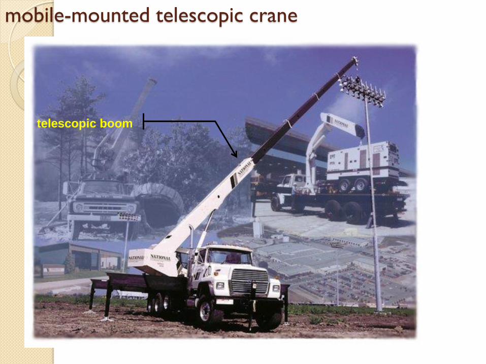
mobile-mounted telescopic crane
telescopic boom

Lattice Boom Truck Cranes

Rough Terrain Cranes

Heavy
Lift
Cranes

Tower Crane
Moving mechanism
1. Install / hook load @ end of hook block
2. Raise hoist rope
3. Turning / swing boom/jib
4. Moving trolley
5. Lower hoist rope
6. Unhook load
7. Raise hoist rope
• e.c.t.
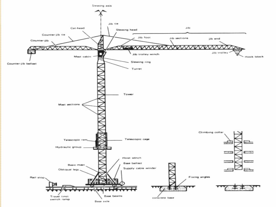

Tower crane
Pendant
Trolley
Top-
slew
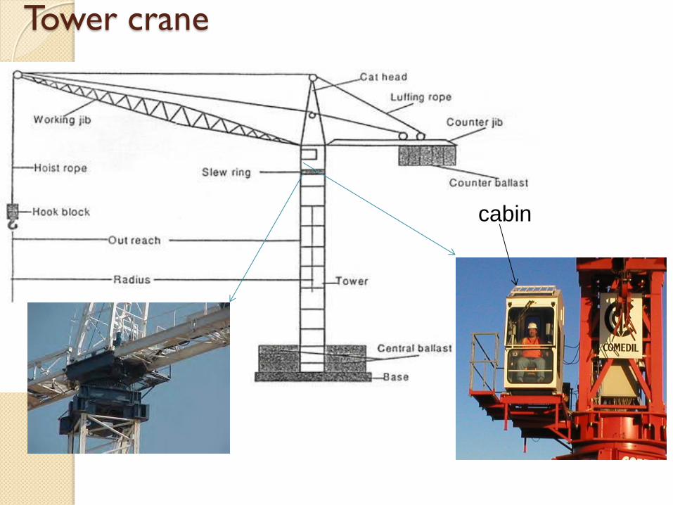
Tower crane
cabin
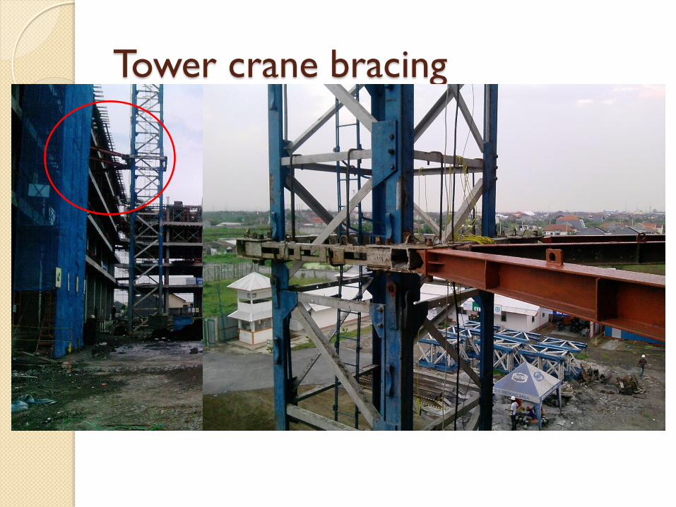
Tower crane bracing

Tower Crane installation
Installation of jib / boom
Installation / extension of tower

Tower Crane’s Self Raising Mechanism
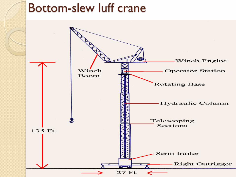
Bottom-slew luff crane
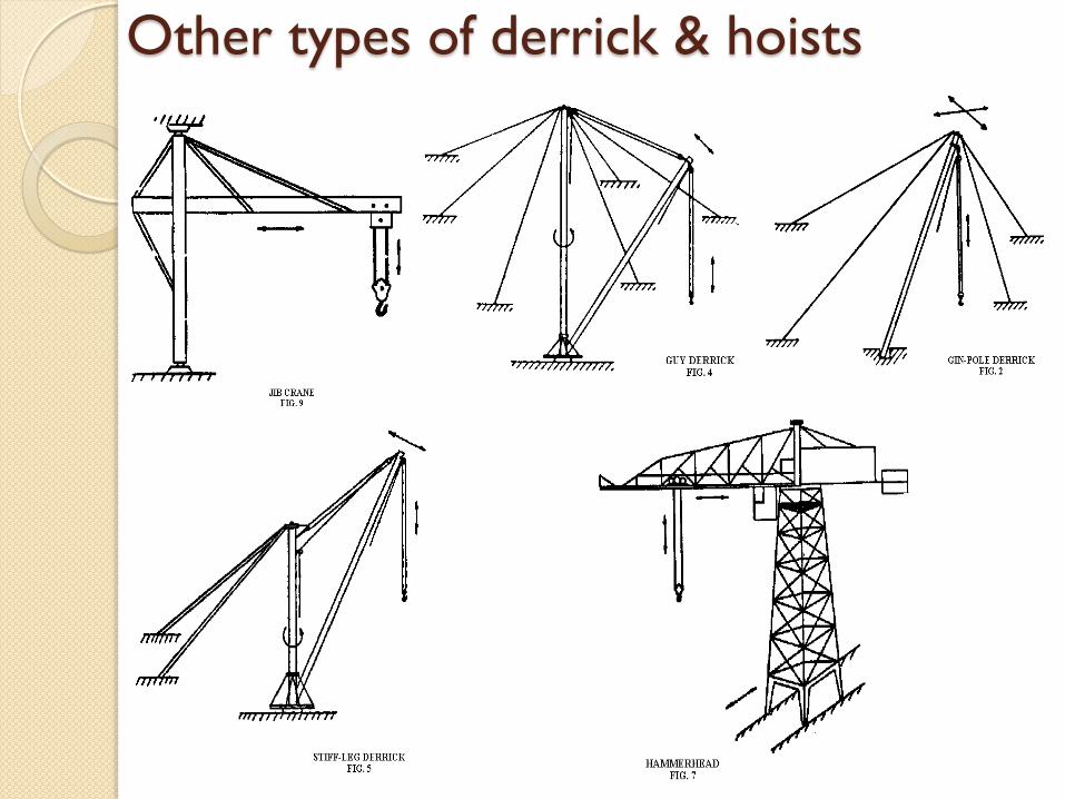
Other types of derrick & hoists

Hoist mechanism
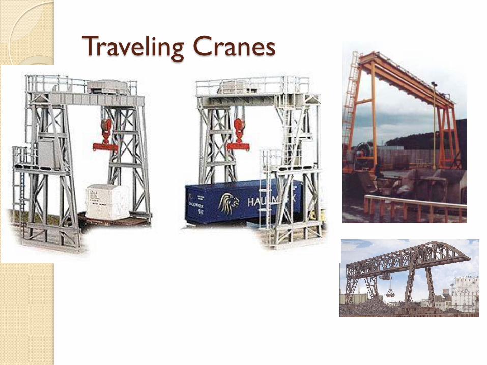
Traveling Cranes

Crane’s Elements

balancing mechanism

stability of mobile crane
Outriggers add to stability by increasing tipping lines and spreading loads
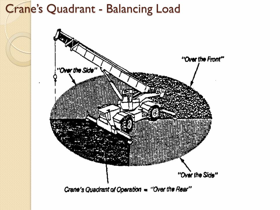
Crane’s Quadrant - Balancing Load

Crane’s Quadrant - Balancing Load
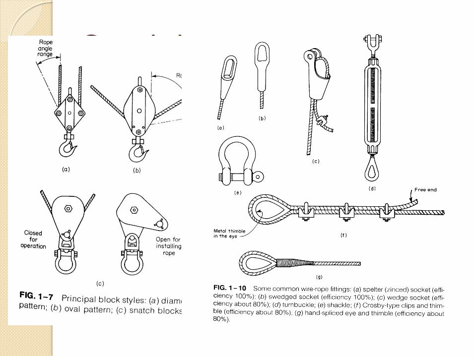
Crane’s Attachments

Crane’s Hooks, Grabs & Bucket

Procedure for determining mobile crane capacity
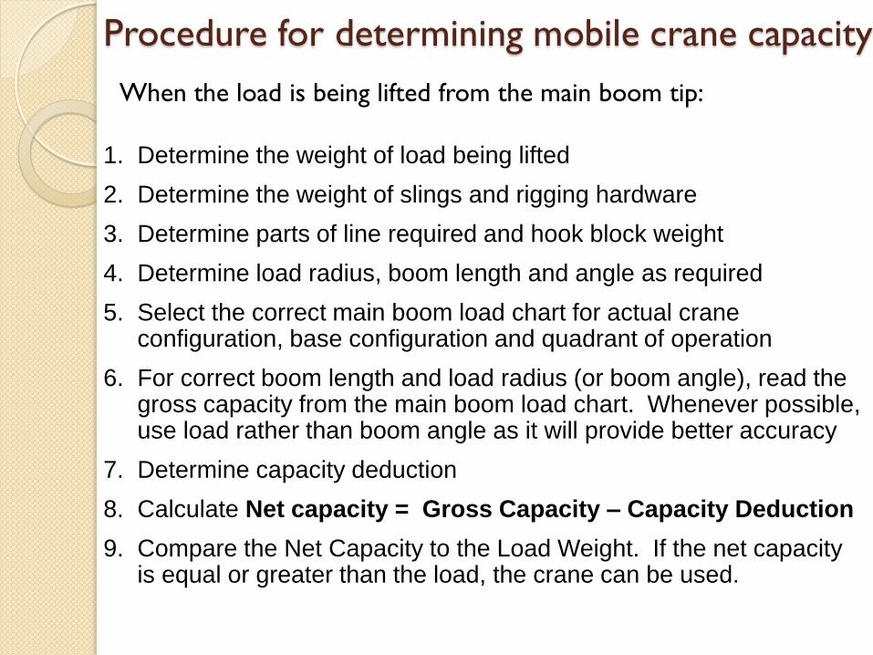
When the load is being lifted from the main boom tip:
1. Determine the weight of load being lifted
2. Determine the weight of slings and rigging hardware
3. Determine parts of line required and hook block weight
4. Determine load radius, boom length and angle as required
5. Select the correct main boom load chart for actual crane configuration, base configuration and quadrant of operation
6. For correct boom length and load radius (or boom angle), read the gross capacity from the main boom load chart. Whenever possible, use load rather than boom angle as it will provide better accuracy
7. Determine capacity deduction
8. Calculate Net capacity = Gross Capacity – Capacity Deduction
9. Compare the Net Capacity to the Load Weight. If the net capacity is equal or greater than the load, the crane can be used.

Capacity Design
Gross capacity ◦ The capacity listed in the load chart are NOT the
load that can be suspended from crane hook
Determining Range of Boom ◦ Determine weight of load or object to be lifted ◦ Determine height of lift ◦ Calculate total height of attachment (block, sling,
hook) ◦ Determine distance of object from the center
(radius)
Capacity Deduction ◦ Weight of hook block ◦ Weight of slings and rigging hardware ◦ Effective weight of boom or jib extension ◦ Weight of auxiliary hook and headache ball ◦ Weight of auxiliary hoist line hanging below boom
extension tip ◦ Stowed weight of jib
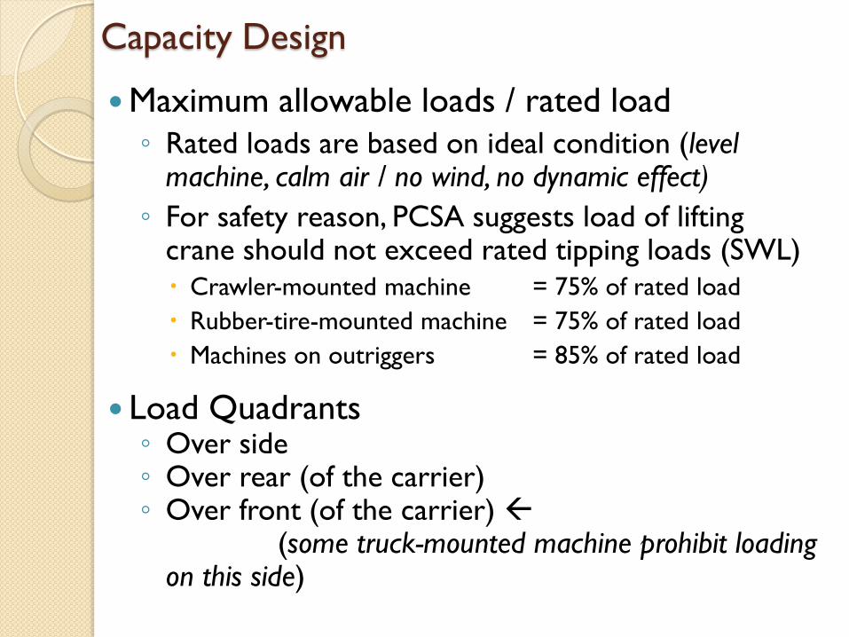
Maximum allowable loads / rated load
◦ Rated loads are based on ideal condition (level machine, calm air / no wind, no dynamic effect)
◦ For safety reason, PCSA suggests load of lifting crane should not exceed rated tipping loads (SWL)
Crawler-mounted machine = 75% of rated load
Rubber-tire-mounted machine = 75% of rated load
Machines on outriggers = 85% of rated load
Load Quadrants ◦ Over side ◦ Over rear (of the carrier) ◦ Over front (of the carrier)
(some truck-mounted machine prohibit loading on this side)
Capacity Design

Load Radius
◦ Is the horizontal distance measured from the center rotation of the crane (center pin) to the load hook (center of gravity of the load)
◦ Load radius is more critical than boom length or boom angle when establishing crane capacity
◦ DO NOT interpolate (extrapolate) values in load chart. Use the gross capacity for the next longer radius listed in the chart
Capacity Design

Crane Capacity Example
Can the tower crane, whose load chart is
shown in the previous table, lift a 15,000-
lb load at a radius of 142 feet? The crane
has a L-7 jib and a two part line hoist.
The slings that will be used for the pick
weigh 400 lb.

Crane Capacity Solution
Weight of load = 15,000 lb
Weight of rigging = 400 lb (slings)
Required Capacity = 15,400 lb.
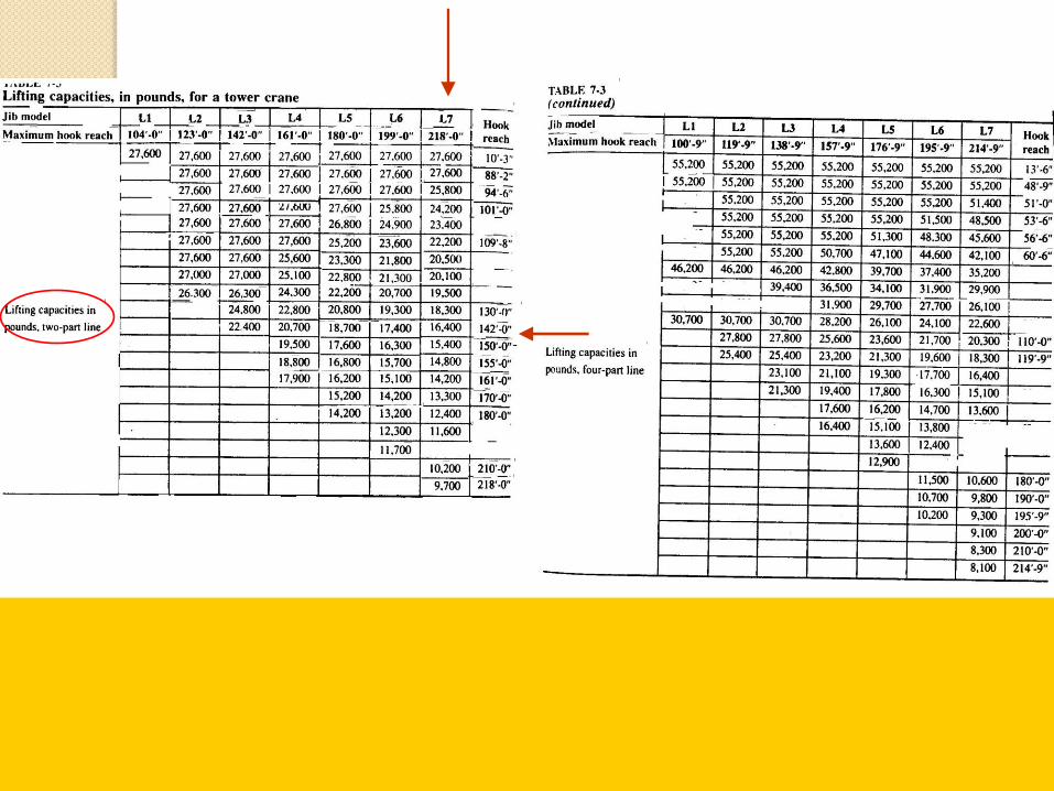
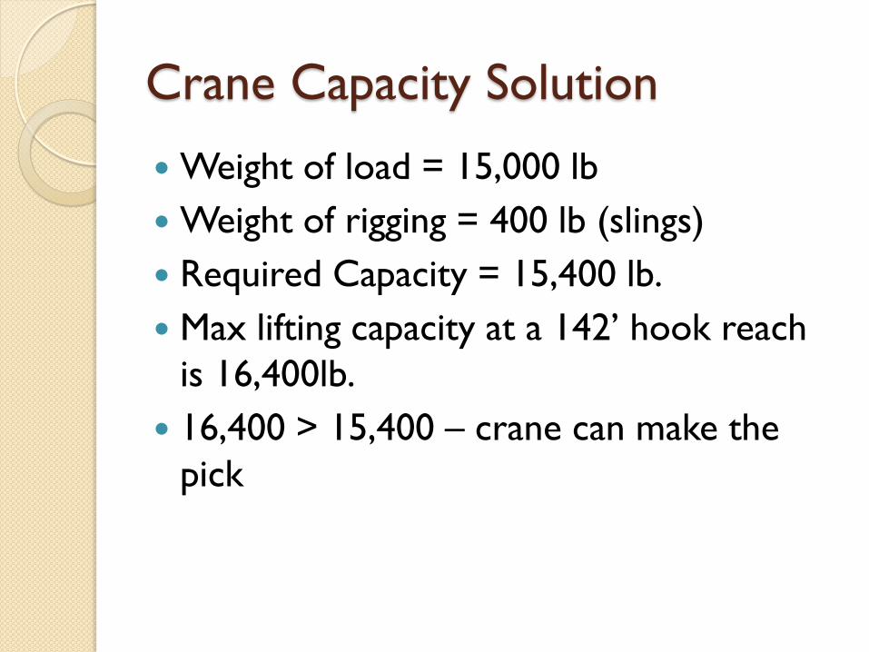
Crane Capacity Solution
Weight of load = 15,000 lb
Weight of rigging = 400 lb (slings)
Required Capacity = 15,400 lb.
Max lifting capacity at a 142’ hook reach
is 16,400lb.
16,400 > 15,400 – crane can make the
pick

3D Simulation modeling for crane-lifting design

3D Simulation modeling for crane-lifting design
dual-cranes lift

3D Simulation modeling for crane-lifting design
rigging configuration
base configuration
ground pressure
Crane Critical Lift Checklist

Other lifting mechanism

Lifting safety

Lifting safety
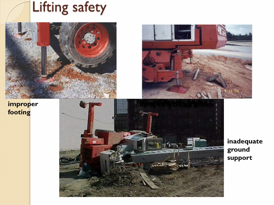
Lifting safety
improper
footing
inadequate
ground
support

Lifting safety too close to power lines
moving with unbalanced object

Lifting safety
Most frequent lifting violations
• Failure to guard swing radius
• Operating near power lines
• No load chart
• Unnecessary use of personnel basket