life expectancy and durability...
TRANSCRIPT
Life Expectancy and DurabilityAssessmentWater Take Resource Consent
Nelson City Council
Document Number: 14000-278-03
Date: 19/12/2014
Prepared by Reviewed by Approved by
Marcus Grierson D McColl R A PuklowskiStructural Engineer Chemical/Environmental Engineer Director

Document Number: 14000-278-03 2
Contents
1. EXECUTIVE SUMMARY....................................................................................................................... 3
2. INTRODUCTION .................................................................................................................................. 4
3. MAITAI INTAKE STRUCTURE – SOUTH BRANCH........................................................................... 6
3.1. INTAKE STRUCTURE ....................................................................................................................................................... 73.2. SCREEN HUT................................................................................................................................................................... 93.3. MAITAI INTAKE STRUCTURE SUMMARY AND RECOMMENDATIONS ........................................................................ 9
4. RODING DAM.................................................................................................................................... 10
4.1. SPILLWAY FACE ............................................................................................................................................................124.2. STEEL TRUSS BRIDGE ...................................................................................................................................................164.3. WESTERN ACCESS .......................................................................................................................................................194.4. EASTERN ACCESS .........................................................................................................................................................224.5. SCREEN TOWER............................................................................................................................................................264.6. CHLORINATOR HOUSE ................................................................................................................................................294.7. PIPELINE WALKWAY ....................................................................................................................................................304.8. SURGE CHAMBER AND ASSOCIATED STRUCTURE .....................................................................................................344.9. RODING DAM SUMMARY AND RECOMMENDATIONS.............................................................................................35
5. LIMITATIONS..................................................................................................................................... 35
6. REFERENCES ...................................................................................................................................... 37

Document Number: 14000-278-03 3
1. Executive Summary
CGW has been engaged by Nelson City Council (NCC) to complete a structural andlife cycle assessment of two dams, the Maitai Dam Intake Structure – South Branchand the Roding Dam Structure.
This assessment involved a site inspection to assess the condition of visible sectionsof the dam and associated components. The inspection did not include anydestructive testing, nor was it a dam safety/dam break assessment.
This assessment found that the Maitai Dam Intake Structure – South Branch isgenerally in sound aged condition with some aesthetic defects. Overall, the residualdesign life of the key structural components is estimated to be in the order of 30years. It is likely this could be extended with regular maintenance. The service life ofsome ancillary components could be less than 30 years, for example deep pittingwas observed on the steel sluice valve and this should be subject to a more detailedcondition assessment.
Components of the Roding Dam critical to system operation were generally foundto be in acceptable condition consistent with the age of the infrastructure. Theresidual service life of the intake structure is estimated to be in the order of 30 yearshowever it is noted that the depth of concrete spalling cannot be assessed whilstthe structure remains in operation. Again, it is likely that routine maintenance, forexample the application of a mortar topping to the inlet structure, could prolongthis estimate.
A number of defects were observed in the pipeline leading to the Roding WaterTunnel including a significant leak. Without adequate maintenance, these defectsmay lead to a failure of the pipeline.
A number of aspects of the Western Roding Dam access way were found to be inpoor condition or non-compliant with current standards. Sections of the EasternRoding Dam access way were found to have effectively reached the end of theirservice life and further work is required to ensure access can continue in a safemanner.
It is recommended that an inspection and maintenance schedule is implemented forboth of these structures. This will allow deterioration of critical features to be betterunderstood over time, improving the accuracy of life cycle assessments.
Document Number: 14000-278-03 4
2. Introduction
CGW has been engaged by Nelson City Council (NCC) to complete a structural, lifecycle and durability assessment of the Maitai Dam Intake Structure – South Branchand the Roding Dam Structure.
Durability and life cycle assessment of components or a structure withoutcomprehensive destructive testing relies on a number of assumptions.
This assessment is based on the study of the available original constructiondrawings and site visits to inspect the visible portions of each structure to providevisual cues of degradation.
The main factors affecting life cycle which may call for upgrading of these structuresare as follows:
i. Changes in the design criteria based on information obtained since theinitial design
ii. Changes in methods of analysis and new safety conceptsiii. Results of risk assessmentsiv. Ageing of construction and foundation materials and components.
This report is focussed on item iv above being ageing of construction andfoundation materials and components.
Residual Life Estimate
Where possible, a residual service life has been estimated for critical components. Incases where observed wear could not be estimated with a reasonable degree ofcertainty, a residual service life has not been estimated. A residual service life hasnot been estimated for all ancillary components where the impact of their failure isconsidered unlikely to prevent operation of the system.
Where a structure is worn, the residual life has been estimated based on thefollowing factors
Expected design life Age of the structure Observed wear compared to the minimum acceptable standard for the
component to remain in serviceIn cases where adequate information was available in as-built drawings, designservice life has been estimated based on AS/NZS 3101 (Standards New Zealand,2006). In the absence of more detailed information, the residual service life forancillary concrete structures has been calculated assuming a design service life of100 years. This is based on AS/NZS 4058 which states that the design life for buriedconcrete pipe is 100 years (Standards New Zealand, 2007). The empiricallycalculated remaining service life was compared to the condition of a given structureto estimate a residual service life. Where a structure is currently damaged to the

Document Number: 14000-278-03 5
extent that it is unusable or assessed to be unsafe, it has been assigned a residuallife of 0 years
It is accepted that concrete structures on site were not built to current standardsand structures which are not buried are likely to be subjected to a more aggressiveenvironment. It is recognised that well maintained structures can exceed this designlife.
The Transit New Zealand Bridge Inspection and Maintenance Manual was used toprovide guidance on assessing both concrete and steel structures. This documentdoes not provide specific design lives for structures, recognising that the design lifeis dependent on the completion of maintenance (Transit New Zealand, 2001).
The New Zealand Concrete Code (Standards New Zealand 2001) has been consultedfor guidance in assessing concrete components. The Steel Structures Standard(Standards New Zealand, 2009) chapter 5 was also referred to for guidance oncorrosion protection requirements.
Defect Classification
Defects observed in structures and associated components have been classified asfollows.
Critical: The observed defect could lead to a failure which will prevent the operationof the infrastructure for its required purpose, the diversion of water to the NCCWater Treatment Plant.
Non-Critical: The observed defect is unlikely to lead to a failure which will preventthe diversion of water to the Water Treatment Plant.
Safety: Failure of this item presents a risk to operator or public safety.

Document Number: 14000-278-03 6
3. Maitai Intake Structure – South Branch
The South Branch Intake is located approximately 985m upstream of the NorthBranch confluence in the vicinity of the Maitai Dam. In plan, this structure is crossshaped constructed of precast concrete walls shown to be tied together on thedesign drawings with post tensioned super strand. Overall design dimensions show6.35m x 5.30m. As-built drawing information provided by NCC indicates that thisintake was constructed in 1986.
Only the visible and easily accessible portions of the intake were inspected and havebeen considered in this report.
Plate 1 - Maitai Intake Structure – South Branch
Document Number: 14000-278-03 7
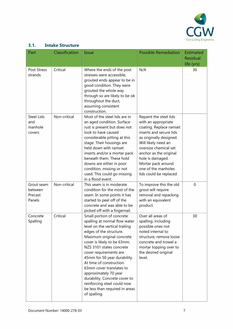
3.1. Intake Structure
Part Classification Issue Possible Remediation EstimatedResiduallife (yrs)
Post Stressstrands
Critical Where the ends of the poststresses were accessible,grouted ends appear to be ingood condition. They weregrouted the whole waythrough so are likely to be okthroughout the duct,assuming consistentconstruction.
N/A 30
Steel Lidsandmanholecovers
Non-critical Most of the steel lids are inan aged condition. Surfacerust is present but does notlook to have causedconsiderable pitting at thisstage. Their housings areheld down with ramsetinserts and/or a mortar packbeneath them. These holddowns are either in poorcondition, missing or notused. This could go missingin a flood event.
Repaint the steel lidswith an appropriatecoating. Replace ramsetinserts and secure lidsas originally designed.Will likely need anoversize chemical setanchor as the originalhole is damaged.Mortar pack aroundone of the manholeslids could be replaced
Grout seambetweenPrecastPanels
Non-critical This seam is in moderatecondition for the most of theseam. In some points it hasstarted to peel off of theconcrete and was able to bepicked off with a fingernail.
To improve this the oldgrout will requireremoval and repackingwith an equivalentproduct.
0
ConcreteSpalling
Critical Small portion of concretespalling at normal flow waterlevel on the vertical trailingedges of the structure.Maximum original concretecover is likely to be 63mm.NZS 3101 states concretecover requirements are45mm for 50 year durability.At time of construction63mm cover translates toapproximately 70 yeardurability. Concrete cover toreinforcing steel could nowbe less than required in areasof spalling.
Over all areas ofspalling, includingpossible ones notnoted internal tostructure, remove looseconcrete and trowel amortar topping over tothe desired originallevel.
30
Document Number: 14000-278-03 8
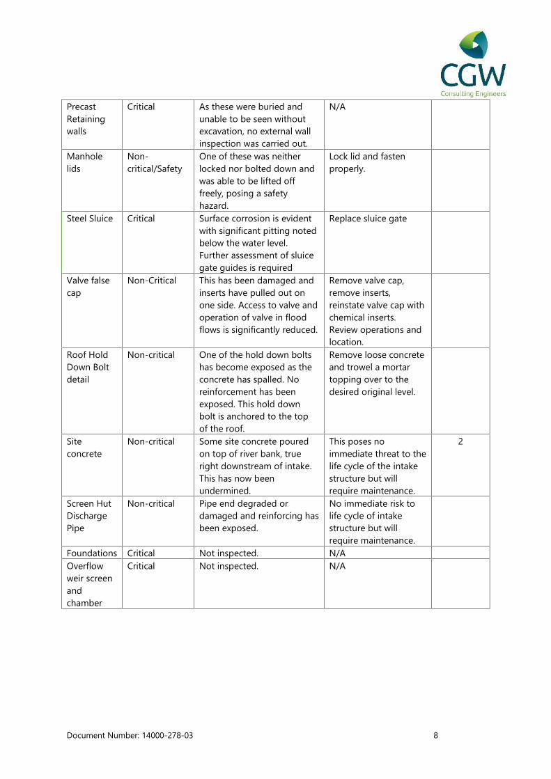
PrecastRetainingwalls
Critical As these were buried andunable to be seen withoutexcavation, no external wallinspection was carried out.
N/A
Manholelids
Non-critical/Safety
One of these was neitherlocked nor bolted down andwas able to be lifted offfreely, posing a safetyhazard.
Lock lid and fastenproperly.
Steel Sluice Critical Surface corrosion is evidentwith significant pitting notedbelow the water level.Further assessment of sluicegate guides is required
Replace sluice gate
Valve falsecap
Non-Critical This has been damaged andinserts have pulled out onone side. Access to valve andoperation of valve in floodflows is significantly reduced.
Remove valve cap,remove inserts,reinstate valve cap withchemical inserts.Review operations andlocation.
Roof HoldDown Boltdetail
Non-critical One of the hold down boltshas become exposed as theconcrete has spalled. Noreinforcement has beenexposed. This hold downbolt is anchored to the topof the roof.
Remove loose concreteand trowel a mortartopping over to thedesired original level.
Siteconcrete
Non-critical Some site concrete pouredon top of river bank, trueright downstream of intake.This has now beenundermined.
This poses noimmediate threat to thelife cycle of the intakestructure but willrequire maintenance.
2
Screen HutDischargePipe
Non-critical Pipe end degraded ordamaged and reinforcing hasbeen exposed.
No immediate risk tolife cycle of intakestructure but willrequire maintenance.
Foundations Critical Not inspected. N/AOverflowweir screenandchamber
Critical Not inspected. N/A

Document Number: 14000-278-03 9
3.2. Screen Hut
Part Classification Issue PossibleRemediation
EstimatedResiduallife (yrs)
ScreenHut
Non-critical Good overall condition. In times of floodflows this hut becomes inundated andaccess is impeded. Flooding of will have aneffect of design life of building andequipment.
Reviewoperations andlocation
3.3. Maitai Intake Structure Summary and Recommendations
Inspections have shown that the structure is in good aged condition with someaesthetic defects, however some areas need attention with regard to design,maintenance and review of operational procedures. In particular the steel sluicevalve should be assessed further and replaced if required. Lack of maintenance anddifficult operational procedures have an effect on the life expectancy of thestructure. Overall this structure is considered to have weathered well and isestimated to have a residual life expectancy of approximately 30 years.
It is recommended that a regular inspection and maintenance program isimplemented to ensure deterioration in observed conditions can be identified andrepaired as required. In particular, depth of concrete spalling should be monitoredand a protective coating should be applied if the rate of spalling rapidly increases.Further inspection of steel sluice valve should be completed to determine the extentof corrosion on the sluice gate and guide channels. This may involve inspectionfrom the waterway.

Document Number: 14000-278-03 10
4. Roding Dam
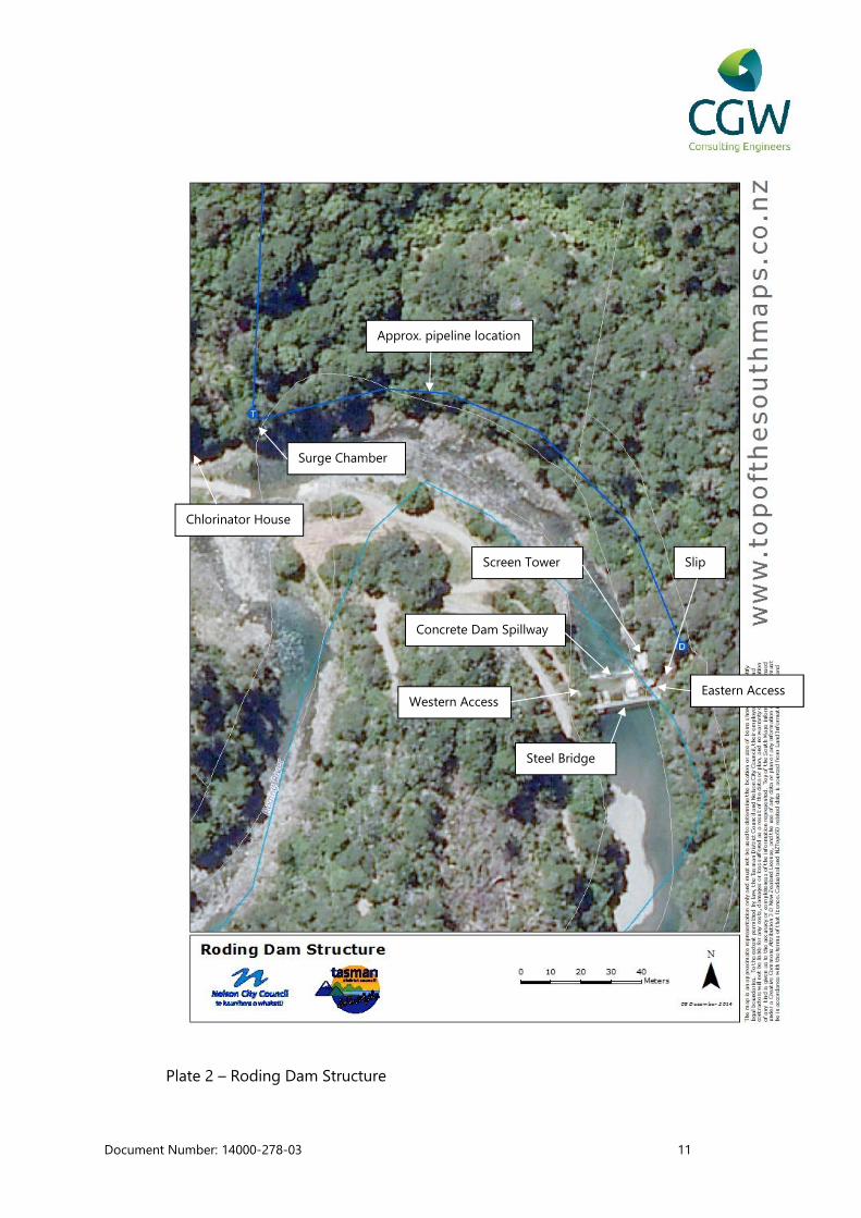
Based on the supplied drawings, it is understood that construction of the Roding
Dam commenced construction in 1937 prior to supply of water to Nelson in 1941.
The dam wall was raised by 1.5m in 1972 to increase the volume of water stored in
the dam and increase the maximum diversion rate to 24,000 m3/day (Bathgate, J,
2008). Drawings supplied by NCC indicate that a new intake structure was added in
1986. The dam consists of a concrete weir with additional structures and
components required for operational activities including
A steel bridge and walkways
Cantilevered concrete stairs
Inlet screen
Chlorination hut
All of the visible and easily accessible portions these components were included in
the scope of this assessment. Some components have been replaced following
flood damage, for example the steel bridge. Other components, for example a steel
section of the walkway, appear to have been temporarily repaired following a slip
event; this repair has subsequently become a permanent feature of the site. Site
observations indicate that structures may be used for purposes not considered in
the original design, for example, the winching of gates and sluices from the bridge.
Individual components are discussed in more detail subsequently.
Document Number: 14000-278-03 11
Plate 2 – Roding Dam Structure
Steel Bridge
Concrete Dam Spillway
Approx. pipeline location
Slip
Western AccessEastern Access
Screen Tower
Chlorinator House
Surge Chamber

Document Number: 14000-278-03 12
4.1. Spillway Face
The concrete spillway face has steel channels directing the mean water flow over the
intake structure. The intake structure was added to the spillway face in 1986. Behind
the dam is full with gravels almost to the level of the spillway crest. It is not known
whether the dam is reinforced or not, but it is expected that it is an unreinforced
mass concrete structure.
Plate 3 - Spillway face and water intake
Document Number: 14000-278-03 13
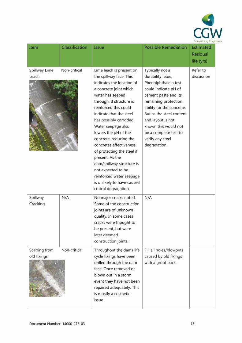
Item Classification Issue Possible Remediation Estimated
Residual
life (yrs)
Spillway Lime Non-critical
Leach
Lime leach is present on
the spillway face. This
indicates the location of
a concrete joint which
water has seeped
through. If structure is
reinforced this could
indicate that the steel
has possibly corroded.
Water seepage also
lowers the pH of the
concrete, reducing the
concretes effectiveness
of protecting the steel if
present. As the
dam/spillway structure is
not expected to be
reinforced water seepage
is unlikely to have caused
critical degradation.
Typically not a
durability issue,
Phenolphthalein test
could indicate pH of
cement paste and its
remaining protection
ability for the concrete.
But as the steel content
and layout is not
known this would not
be a complete test to
verify any steel
degradation.
Refer to
discussion
Spillway
Cracking
N/A No major cracks noted.
Some of the construction
joints are of unknown
quality. In some cases
cracks were thought to
be present, but were
later deemed
construction joints.
N/A
Scarring from Non-critical
old fixings
Throughout the dams life
cycle fixings have been
drilled through the dam
face. Once removed or
blown out in a storm
event they have not been
repaired adequately. This
is mostly a cosmetic
issue
Fill all holes/blowouts
caused by old fixings
with a grout pack.
Document Number: 14000-278-03 14
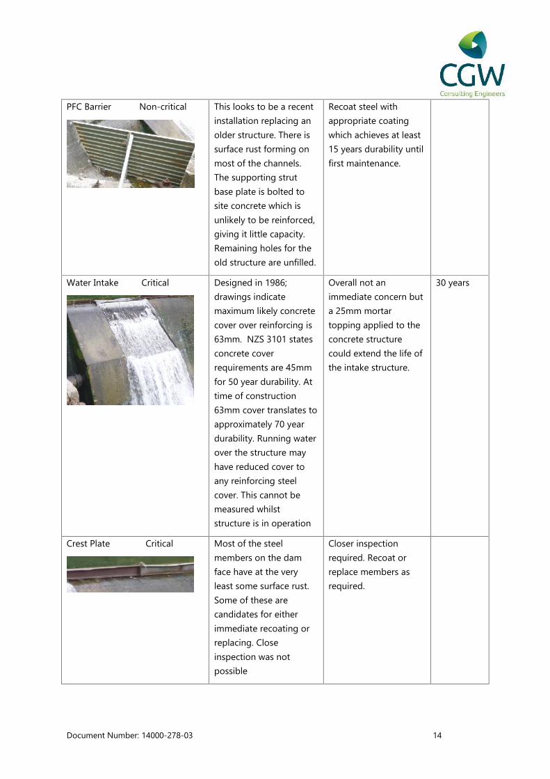
PFC Barrier Non-critical This looks to be a recent
installation replacing an
older structure. There is
surface rust forming on
most of the channels.
The supporting strut
base plate is bolted to
site concrete which is
unlikely to be reinforced,
giving it little capacity.
Remaining holes for the
old structure are unfilled.
Recoat steel with
appropriate coating
which achieves at least
15 years durability until
first maintenance.
Water Intake Critical Designed in 1986;
drawings indicate
maximum likely concrete
cover over reinforcing is
63mm. NZS 3101 states
concrete cover
requirements are 45mm
for 50 year durability. At
time of construction
63mm cover translates to
approximately 70 year
durability. Running water
over the structure may
have reduced cover to
any reinforcing steel
cover. This cannot be
measured whilst
structure is in operation
Overall not an
immediate concern but
a 25mm mortar
topping applied to the
concrete structure
could extend the life of
the intake structure.
30 years
Crest Plate Critical Most of the steel
members on the dam
face have at the very
least some surface rust.
Some of these are
candidates for either
immediate recoating or
replacing. Close
inspection was not
possible
Closer inspection
required. Recoat or
replace members as
required.

Document Number: 14000-278-03 15
The Roding dam spillway and intake structure were assessed to be in acceptable agedcondition. Based on the construction and condition of the intake structure, the residualservice life is estimated to be in the order of 30 years. Regular maintenance, for example thetopping of the intake structure with an appropriate mortar could further prolong the servicelife. The spillway pre-dates the intake structure however this is likely to be a mass concretestructure, site observations did not reveal any defects which would lead the estimatedresidual service life to be reduced below that of the intake structure.

Document Number: 14000-278-03 16
4.2. Steel Truss Bridge
Plate 4 – Steel Truss Bridge
The bridge spans approximately 20m and is of steel construction. The top rail is constructed
from Square Hollow Section steel (SHS) and the bottom is a steel angle. There is a Parallel
Flange Channel (PFC) transom running between the vertical truss members. There is no
current load restriction on this bridge and it is open to public access.
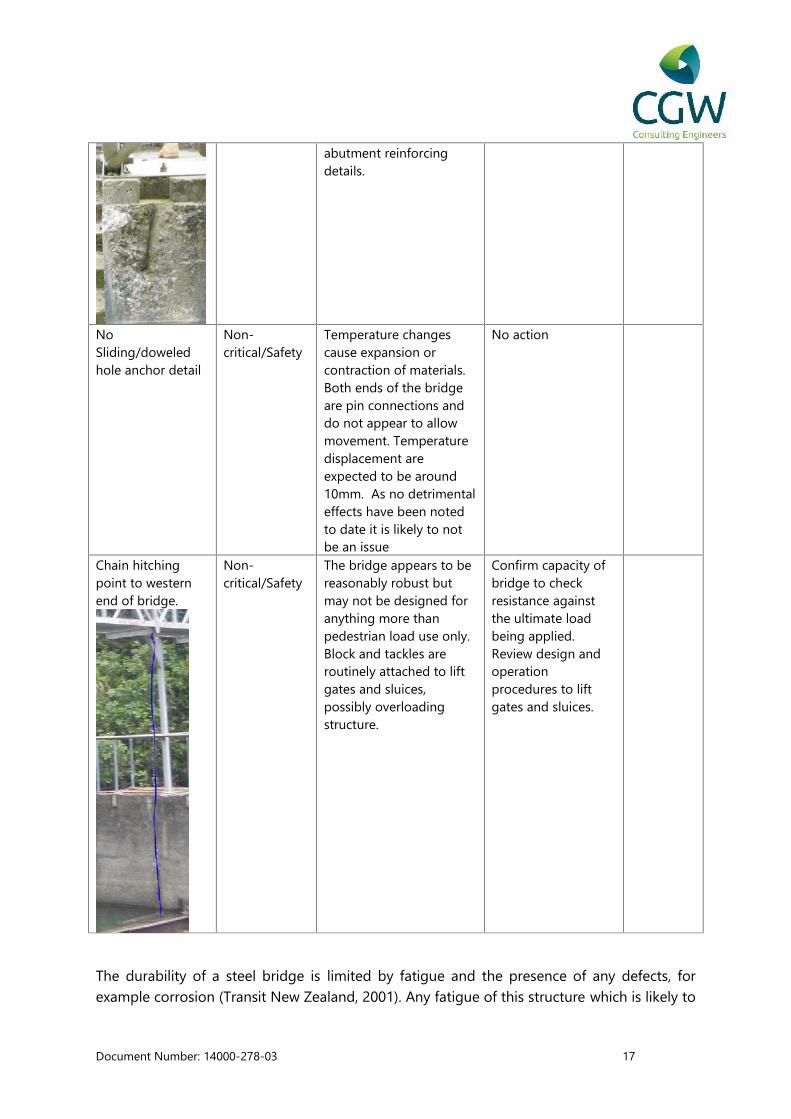
Item Classification Issue PossibleRemediation
EstimatedResiduallife (yrs)
Joint at mid spanof bridge – sitewelded
Non-critical/Safety
This part of the bridge isunder the largest bendingmoment demand. Thejoint is also the pointwhere the mostsignificant corrosion hasoccurred. At this stagerust penetration does notappear to be deep.
Further inspectcorrosion depth andstrengthen locally asrequired. It ispossible that theentire bridge coatingis reaching its lifeexpectancy. Recoatentire bridge withappropriate paintsystem.
Refer todiscussion
Anchor bolts/plate Non-critical/Safety
Details of these bolts arenot shown on plans.Possible issues for thesebolts are edge distances,embedment depth,unknown substratestrength and unknown
Carry out a structuralanalysis on thisbridge to determinereactions on bolts todetermine theircapacity.
Document Number: 14000-278-03 17
abutment reinforcingdetails.
NoSliding/doweledhole anchor detail
Non-critical/Safety
Temperature changescause expansion orcontraction of materials.Both ends of the bridgeare pin connections anddo not appear to allowmovement. Temperaturedisplacement areexpected to be around10mm. As no detrimentaleffects have been notedto date it is likely to notbe an issue
No action
Chain hitchingpoint to westernend of bridge.
Non-critical/Safety
The bridge appears to bereasonably robust butmay not be designed foranything more thanpedestrian load use only.Block and tackles areroutinely attached to liftgates and sluices,possibly overloadingstructure.
Confirm capacity ofbridge to checkresistance againstthe ultimate loadbeing applied.Review design andoperationprocedures to liftgates and sluices.
The durability of a steel bridge is limited by fatigue and the presence of any defects, forexample corrosion (Transit New Zealand, 2001). Any fatigue of this structure which is likely to
Document Number: 14000-278-03 18
have result from applied loads has not been assessed. Based on the site inspection, factorswhich could influence the service life of this bridge include
Maintenance, in particular application of protective coatings Loads in excess of design loading Catastrophic event, for example damage during flood event
The Transit New Zealand Bridge Inspection Manual states that the re-application ofprotective coatings for a steel bridge should occur within 15-25 years of construction toensure the service life is not compromised. In this case, it is understood the bridge wasconstructed in 1986 and it is unclear if any re-application of protective coatings has beencompleted since. The areas of the structure which could be observed during the siteinspection revealed some corrosion which did not appear to have penetrated deeply at thisstage. Actions recommended to prolong the life of this bridge are as follows
1) Treat corrosion and apply an appropriate protective coating2) Complete an assessment of the loadings resulting from current work procedures and
comment on any likely affect upon the service life of the bridge

Document Number: 14000-278-03 19
4.3. Western Access
The dam access starts on a formed track before stairs onto the bridge. There is also a set of
stairs down from the concrete abutments and onto a platform below the bridge.
Item Classification Issue Possible
Remediation
Estimated
Residual life
(yrs)
Track Handrail Non-
critical/Safety
Does not comply with
current standards. It is
attached with a
scaffolding clamp.
Install adequate
handrails and
bannisters to
comply with SNZ
HB 8630
Refer
discussion
Concrete steps Non-critical
. /Safety
These are cantilevered
off of the abutment.
Based on the original
design drawings, it
appears that steel mesh
has been bent as
reinforcing in the steps in
a manner which would
not be considered an
acceptable solution
based on current design
standards. There has
been significant spalling
from the old handrail
locations and off of the
bottom of the staircase.
Stairs are doweled into
abutment, likely with
plain round bars only.
Options include
Replace with
stairs which
comply with
current
standards
Make stairs
inaccessible to
the public.
Remove stairs
and replace with
ladder
Handrails Non-
critical/Safety
Removal of old handrail
caused concrete to
blowout. The handrail is
generally just a single
handrail. In some cases,
deer fencing has been
used in an attempt to
block the gap between
the stairs and hand rail.
This does not comply
Replace with
handrail
compliant with
current
standards
Mortar over the
areas of damage.
Document Number: 14000-278-03 20
with current standards
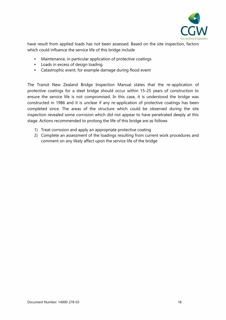
Original Precast
Steps
Non-
critical/Safety
On the downriver side on
the west some precast
steps were once
installed. These have
been removed or
destroyed at some stage.
The steel bars epoxied
into the concrete remain
protruding.
Remove excess
steel and grout
over.
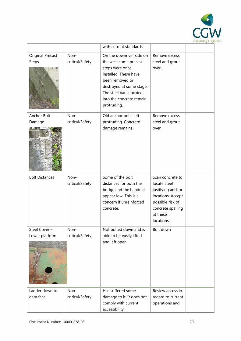
Anchor Bolt
Damage
Non-
critical/Safety
Old anchor bolts left
protruding. Concrete
damage remains.
Remove excess
steel and grout
over.
Bolt Distances Non-
critical/Safety
Some of the bolt
distances for both the
bridge and the handrail
appear low. This is a
concern if unreinforced
concrete.
Scan concrete to
locate steel
justifying anchor
locations. Accept
possible risk of
concrete spalling
at these
locations.
Steel Cover –
Lower platform
Non-
critical/Safety
Not bolted down and is
able to be easily lifted
and left open.
Bolt down
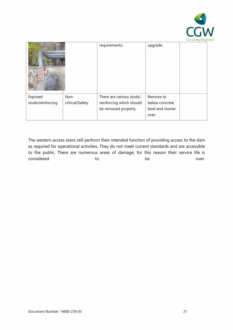
Ladder down to
dam face
Non-
critical/Safety
Has suffered some
damage to it. It does not
comply with current
accessibility
Review access in
regard to current
operations and
Document Number: 14000-278-03 21
requirements. upgrade.
Exposed
studs/reinforcing
Non-
critical/Safety
There are various studs/
reinforcing which should
be removed properly.
Remove to
below concrete
level and mortar
over.
The western access stairs still perform their intended function of providing access to the damas required for operational activities. They do not meet current standards and are accessibleto the public. There are numerous areas of damage; for this reason their service life isconsidered to be over.
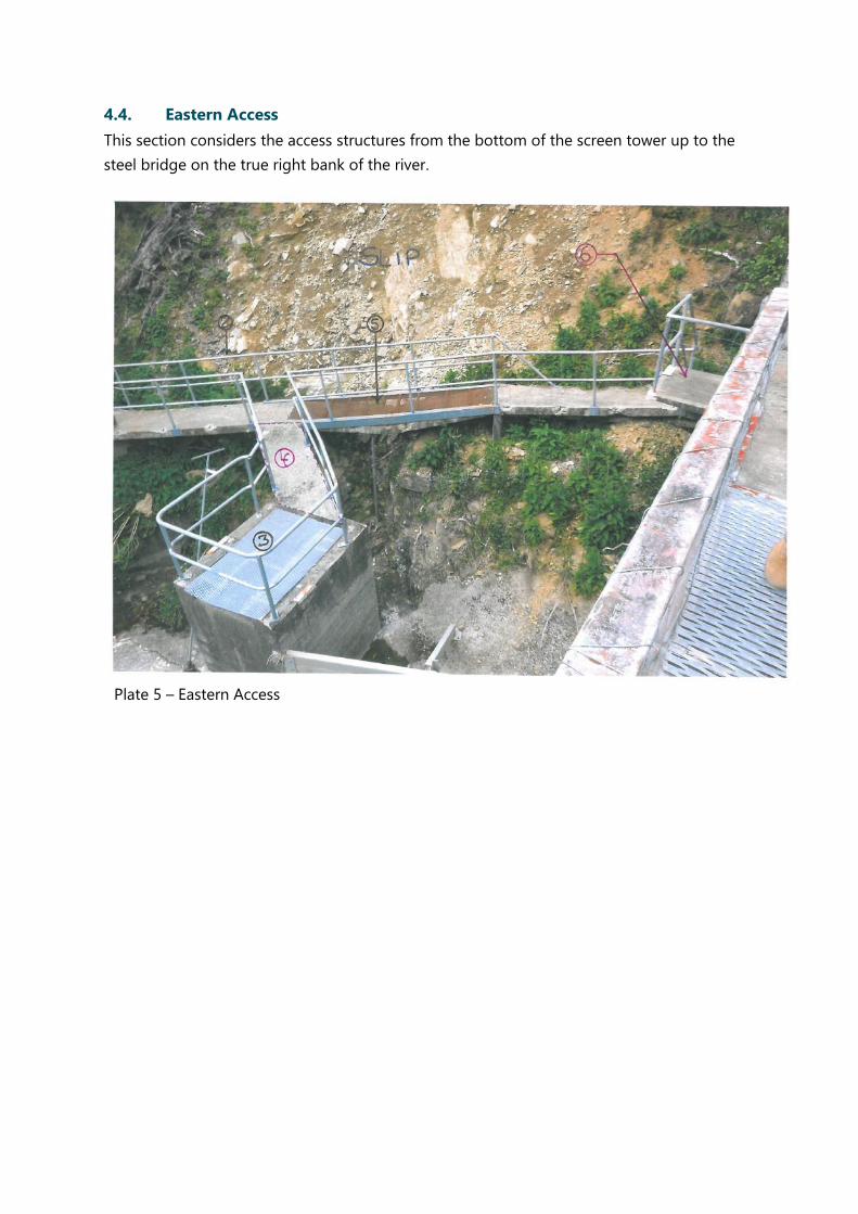
4.4. Eastern Access
This section considers the access structures from the bottom of the screen tower up to the
steel bridge on the true right bank of the river.
Plate 5 – Eastern Access

Document Number: 14000-278-03 23
Item Classification Issue Possible
Remediation
Estimated
Residual
life (yrs)
Steps on sideof screen tower
Non-critical/
Safety
There are two types of stairs, a
precast cantilevered stair and an
in situ stair. These finish in a
cantilever platform off the screen
tower. The insitu stairs are in
good condition but the precast
steps are at the end of their life
cycle. The ends have spalled off
and are poorly repaired. One step
has a large crack through the
entire the step.
Replace
cantilevered
stairs.
0
Handrail (Refer 2
in Plate 5 above)
Non-
critical/Safety
The existing walkway handrails
have suffered impact from slip
debris causing damage to the
fixings and concrete. The
replacement handrail appears
adequate however design
requirements are unknown and
the fixing bolt edge distances
appear to be inadequate for the
thin concrete slab.
Mesh Grating at
scour valve
chamber (Refer 3
in Plate 5 above)
Non-
critical/Safety
It has failed and permanently
deformed.
Replace. 0
Walkway to
scour valve
chamber (Refer 4
in Plate 5 above)
Non-
critical/Safety
Appears to be acting as a strut
for the rest of the walkway
resisting horizontal loads. This
would represent unintended
design forces on viewing
platform abutments
Replace as
part of
walkway
replacement
works.
0
Temporary Metal
Deck Walkway
Non-
critical/Safety
Temporary solution using metal
deck over slip damaged concrete
Redesign and
replace.
0
Document Number: 14000-278-03 24
(Refer 5 in Plate
5 above)
appears inadequate. The steel
angles that provide most of the
support are connected to
concrete separate from the stable
strata. This should have been
extended past the failed portion
of decking. Temporarily
supported by an acrow prop.
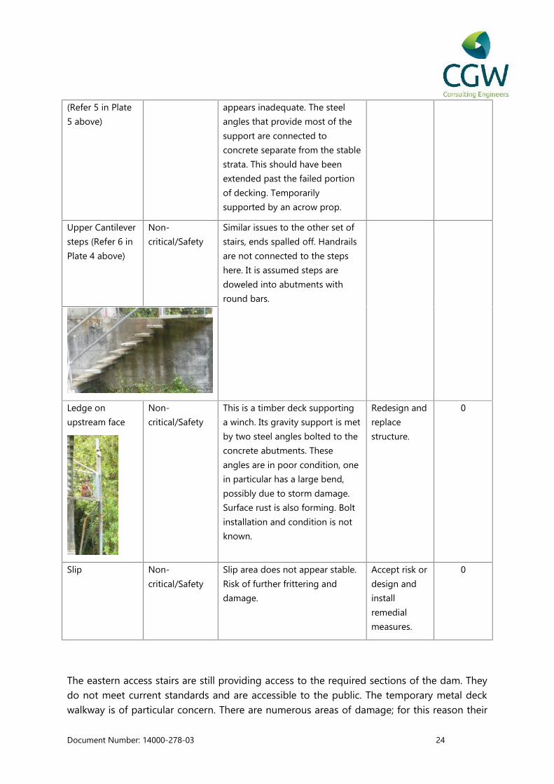
Upper Cantilever
steps (Refer 6 in
Plate 4 above)
Non-
critical/Safety
Similar issues to the other set of
stairs, ends spalled off. Handrails
are not connected to the steps
here. It is assumed steps are
doweled into abutments with
round bars.
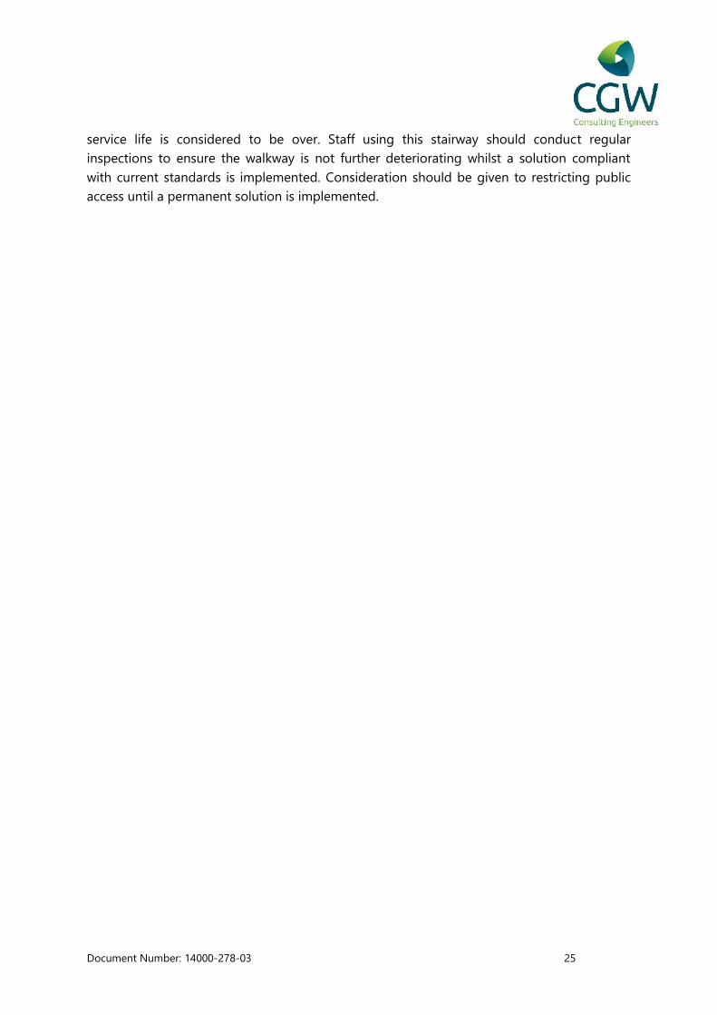
Ledge on
upstream face
Non-
critical/Safety
This is a timber deck supporting
a winch. Its gravity support is met
by two steel angles bolted to the
concrete abutments. These
angles are in poor condition, one
in particular has a large bend,
possibly due to storm damage.
Surface rust is also forming. Bolt
installation and condition is not
known.
Redesign and
replace
structure.
0
Slip Non-
critical/Safety
Slip area does not appear stable.
Risk of further frittering and
damage.
Accept risk or
design and
install
remedial
measures.
0
The eastern access stairs are still providing access to the required sections of the dam. Theydo not meet current standards and are accessible to the public. The temporary metal deckwalkway is of particular concern. There are numerous areas of damage; for this reason their
Document Number: 14000-278-03 25
service life is considered to be over. Staff using this stairway should conduct regularinspections to ensure the walkway is not further deteriorating whilst a solution compliantwith current standards is implemented. Consideration should be given to restricting publicaccess until a permanent solution is implemented.
Document Number: 14000-278-03 26
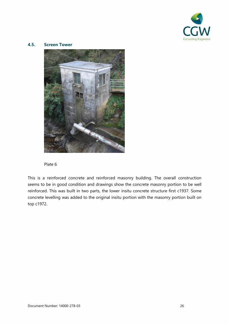
4.5. Screen Tower
Plate 6
This is a reinforced concrete and reinforced masonry building. The overall construction
seems to be in good condition and drawings show the concrete masonry portion to be well
reinforced. This was built in two parts, the lower insitu concrete structure first c1937. Some
concrete levelling was added to the original insitu portion with the masonry portion built on
top c1972.
Document Number: 14000-278-03 27
Item Classification Issue Possible
Remediation
Estimated
Residual
life (yrs)
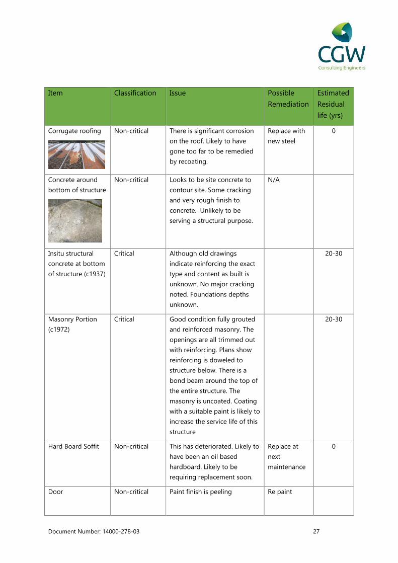
Corrugate roofing Non-critical There is significant corrosion
on the roof. Likely to have
gone too far to be remedied
by recoating.
Replace with
new steel
0
Concrete around
bottom of structure
Non-critical Looks to be site concrete to
contour site. Some cracking
and very rough finish to
concrete. Unlikely to be
serving a structural purpose.
N/A
Insitu structural
concrete at bottom
of structure (c1937)
Critical Although old drawings
indicate reinforcing the exact
type and content as built is
unknown. No major cracking
noted. Foundations depths
unknown.
20-30
Masonry Portion
(c1972)
Critical Good condition fully grouted
and reinforced masonry. The
openings are all trimmed out
with reinforcing. Plans show
reinforcing is doweled to
structure below. There is a
bond beam around the top of
the entire structure. The
masonry is uncoated. Coating
with a suitable paint is likely to
increase the service life of this
structure
20-30
Hard Board Soffit Non-critical This has deteriorated. Likely to
have been an oil based
hardboard. Likely to be
requiring replacement soon.
Replace at
next
maintenance
0
Door Non-critical Paint finish is peeling Re paint

Document Number: 14000-278-03 28
Mildew/Mold Non-critical Due to the damp environment
there is some fungal growth
on the structure.
Wash
regularly
Overturning Critical As it is a slender, tall and
heavy structure, it appears at
risk to overturning in a seismic
event.
Carry out
further
assessment.
The service life of this structure is likely to be limited by the original concrete foundations
upon which the newer masonry section of the building is constructed. Based on assumed
service life of 100 years, and an age of approximately 77 years, the residual service life is
expected to be in the order of 23 years. The structure appears in generally sound condition
and with a maintenance program including replacement of the roof and application of an
appropriate coating, the structure is likely to provide adequate service beyond this point.
Document Number: 14000-278-03 29
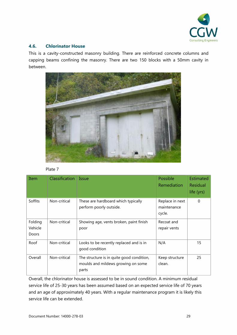
4.6. Chlorinator House
This is a cavity-constructed masonry building. There are reinforced concrete columns and
capping beams confining the masonry. There are two 150 blocks with a 50mm cavity in
between.
Plate 7
Item Classification Issue Possible
Remediation
Estimated
Residual
life (yrs)
Soffits Non-critical These are hardboard which typically
perform poorly outside.
Replace in next
maintenance
cycle.
0
Folding
Vehicle
Doors
Non-critical Showing age, vents broken, paint finish
poor
Recoat and
repair vents
Roof Non-critical Looks to be recently replaced and is in
good condition
N/A 15
Overall Non-critical The structure is in quite good condition,
moulds and mildews growing on some
parts
Keep structure
clean.
25
Overall, the chlorinator house is assessed to be in sound condition. A minimum residual
service life of 25-30 years has been assumed based on an expected service life of 70 years
and an age of approximately 40 years. With a regular maintenance program it is likely this
service life can be extended.
Document Number: 14000-278-03 30
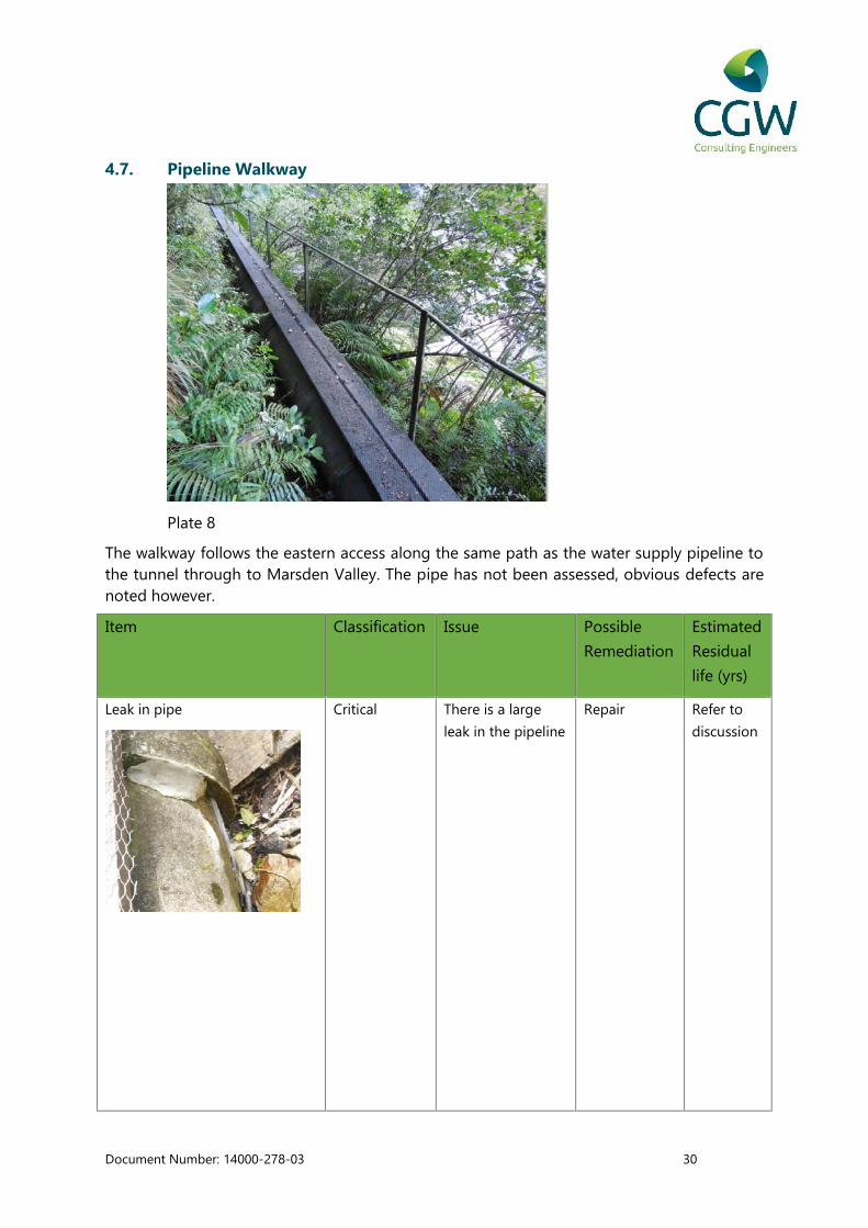
4.7. Pipeline Walkway
Plate 8
The walkway follows the eastern access along the same path as the water supply pipeline tothe tunnel through to Marsden Valley. The pipe has not been assessed, obvious defects arenoted however.
Item Classification Issue Possible
Remediation
Estimated
Residual
life (yrs)
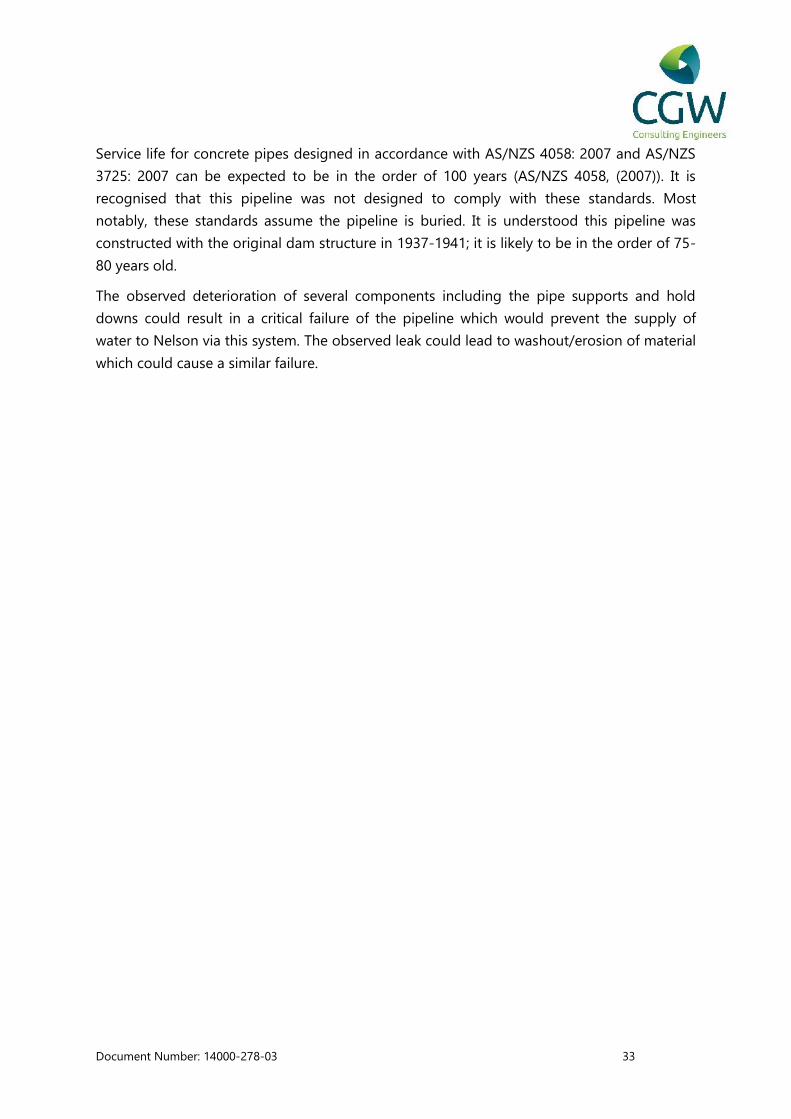
Leak in pipe Critical There is a large
leak in the pipeline
Repair Refer to
discussion

Document Number: 14000-278-03 31
Metal pipe by screen tower Critical There is a dent in
the pipe which
requires
confirmation
whether this
represents a critical
structural
weakness or is
acceptable
Refer to
discussion
Pathway Handrail Non-
critical/Safety
This handrail is in
overall poor
condition.
Accept,
remove or
improve
0
Retaining wall/support to
pipeline.
Critical A concrete/rock
retaining wall is
supporting the
pipeline at or
above ground
level. Some loose
material observed,
no indication of
substantial
movement
Monitor
condition of
retaining
walls.
Consider
installing a
new structure
if significant
changes are
observed.
Refer to
discussion
Pipe supports Critical These look to be
vertical section of
pipe inserted into
the retaining walls
than filled with a
mortar underneath
of the pipe. The
mortar pack has
been missing for a
long time in some
cases, reducing the
bearing area on
the pipe.
Repack with
mortar to
support pipe
Refer to
discussion

Document Number: 14000-278-03 32
Pipe Hold Downs Critical These are
connected to studs
inserted into the
pipe supports.
They are mostly in
poor condition
with a wire or the
stud is near the
end of its life.
Replace 0
Walkway Timbers Non-
critical/Safety
They are in poor
condition and
deflect a different
amount each.
Some are broken
or rotten.
Replace 0
Bannister to pipe Non-
critical/Safety
This connection
allows for rotation
about the pipe in
some places.
Replace
Handrail
0
Steel pipe across long gully The original design drawings (5/77
Sheet 4a) show a bridge to support
the pipeline crossing. The actual
pipeline crossing is a steel pipe with
no bridge. It is unclear if this was a
change made during construction in
1937 or a replacement section of
pipe following damage to the
original
Review NCC
plans
database or
confirm
structural
adequacy for
span.
N/A
Document Number: 14000-278-03 33
Service life for concrete pipes designed in accordance with AS/NZS 4058: 2007 and AS/NZS
3725: 2007 can be expected to be in the order of 100 years (AS/NZS 4058, (2007)). It is
recognised that this pipeline was not designed to comply with these standards. Most
notably, these standards assume the pipeline is buried. It is understood this pipeline was
constructed with the original dam structure in 1937-1941; it is likely to be in the order of 75-
80 years old.
The observed deterioration of several components including the pipe supports and hold
downs could result in a critical failure of the pipeline which would prevent the supply of
water to Nelson via this system. The observed leak could lead to washout/erosion of material
which could cause a similar failure.

Document Number: 14000-278-03 34
4.8. Surge Chamber and associated structure
Item Classification Issue Possible
Remediation
Estimated
Residual
life (yrs)
In ground tank Non-critical Fibreglass tape sealing top
panels has begun to fail and is
easily peeled off
Clean off and
replace with
mortar
25-30
years
Surge Chamber Non-critical Some corrosion of steel
components and weathering of
concrete
Clean and
treat steel
corrosion.
Consider
application of
an
appropriate
coating
Thrust
block/Support
Non-critical Undermined due to erosion.
Unlikely to cause critical failure
in short to medium term
Backfill
material
around thrust
block and
compact to
prevent
further
erosion

Document Number: 14000-278-03 35
Steel Pipes Original corrosion inhibitor has
failed and is flaking off.
Carry out
further pipe
corrosion
assessment.
Treat
corrosion and
apply
protective
coating or
replace.
4.9. Roding Dam Summary and Recommendations
Inspections have shown that the Dam and Spillway structure are in acceptable agedcondition with some aesthetic defects. Overall the concrete structure and associatedbuildings are considered to have weathered well and are estimated to have a residual lifeexpectancy of approximately 25-30 years. The service life of the eastern and western accesswalkways has been assessed to be effectively over due to observed defects. Defects observedin the visible section of the Roding Tunnel pipeline are considered likely to impact upon theexpected residual service life in the short to medium term.
It is recommended that a regular inspection and maintenance program is implemented toensure deterioration in observed conditions can be monitored and rectified as required. Thefollowing activities should be prioritised.
Complete regular maintenance/safety inspections of access ways. Considerrestricting public access
Allocate funding for replacement walkways Apply an appropriate coating to steel truss bridge Complete an assessment of bridge load rating and confirm if current
operational activities are acceptable Complete a detailed condition assessment of pipeline with maintenance as
required
5. Limitations
This report has been prepared solely for the benefit of Nelson City Council for the purpose ofproviding information relating to the condition and estimated residual service life of thestructures identified in this report. The reliance by any other parties on the information oropinions contained in this report shall, without our prior agreement in writing, be at suchparties’ sole risk.
The information contained within this report is based on a visual inspection only ofstructures and associated components above the water level in the respective waterways atthe time of inspection.
Document Number: 14000-278-03 36
This report has been prepared solely to address the issues raised in our brief, and shall notbe relied on for any other purpose.
This report is not a dam safety or dam break assessment and cannot be relied on tocomment upon the likelihood or consequences of dam failure.
Document Number: 14000-278-03 37
6. References
Bathgate, J. (2008) Roding Valley Water Works, Accessed via website 16/12/2014
http://www.theprow.org.nz/enterprise/roding-valley-waterworks/#.VI9Cc2dxnt4
Standards New Zealand. (2006). Concrete Structres Standard. NZS 3101.
Standards New Zealand. (2007) Precast concrete pipes (Pressure and non-pressurised) -AS/NZS 4058
Standards New Zealand. (2009). Steel Structures Standard - NZS 3401:Part 2.
Transit New Zealand. (2001). Bridge Inspection and Maintenance Manual. Wellington: TransitNew Zealand.