library for modbus master communication for modbus rtu master communication 1 introduction libraries...
TRANSCRIPT
R
Library ModbusRTUlibModbus RTU master communication
TXV 003 52.023rd Issue
February 2010All rights reserved

Library for Modbus RTU master communication
History of changesDate Issue Description of changes
April 2009 1 First issue of ModbusRTULib_V10 libraryAugust 2009 2 StAdr range corrected (0000..9999)
Link to constants for chanCode was addedParameter MBtimeOut for the settings of waiting time for response was added New version of ModbusRTUlib_V11 library
February 2010 3 Corrected displaying of ErrCode taken over from ComLibCorrected error message description in the table in chapter 2.5New version of ModbusRTUlib_V12 library
CONTENT
1 Introduction..............................................................................................................31.1 Modbus RTU protocol................................................................................................3
1.2 Memory data encoding .............................................................................................3
1.3 Modbus protocol public functions.............................................................................4
1.4 Modbus Data model ...................................................................................................4
2 Function and Function block for Modbus ...........................................................52.1 Modbus master control commands description........................................................5
2.2 ModbusCmd function.................................................................................................6
2.3 ModbusRTUmas function block...............................................................................7
2.4 GetModbusErrTxt function......................................................................................9
2.5 Error report code......................................................................................................10
3 Communication channel setting............................................................................113.1 Serial channel setting for Modbus master...............................................................11
3.2 Ethernet channel setting for Modbus master .......................................................12
4 Modbus master comunication examples................................................................134.1 Modbus devices nets topology................................................................................13
4.2 Example 1 - communication by serial channel......................................................13
4.3 Example 2 - simple Modbus TCP communication...............................................14
2 TXV 003 52.02

Library for Modbus RTU master communication
1 INTRODUCTIONLibraries of functions and function blocks are an inseparable part of the installation of the
Mosaic programming environment. It is possible to divide them into the following types:
• built-in libraries• standardly supplied external libraries• user defined libraries
A library contains declarations of functions, function blocks, data types and global variables for Modbus master communication. Library ModbusRTUlib uses some functions from ComLib and CrcLib library.
The Library is delivered with the Mosaic development environment from 2.0.16.0 version. Function and Function blocks of ModbusRTUlib library are supported by CPU line K (TC700 CP-7004 and all variants of Foxtrot systems) from version 4.4..
1.1 Modbus RTU protocolThe open serial protocol Modbus RTU was released by Modicon company in 1979. Modbus
is an application layer messaging protocol for client/server communication between devices connec-ted on different types of buses or networks.
Modbus interchanges data between one master and one or more slave devices over asyn-chronous serial lines . Master device queries and the other devices response.
Modbus over Ethernet is called Modbus TCP. The Internet community can access MOD-BUS at a reserved system port 502 on the TCP/IP stack. Principle of data transfer and communica-tion functions is similar Modbus RTU. More clients and servers can communicate all at once in Ethernet networks.
For more details, please see documents at http://www.Modbus-IDA.org :
Modbus_Application_Protocol_V1_1b.pdfModbus_over_serial_line_V1_02.pdfModbus_Messaging_Implementation_Guide_V1_0b.pdfOpen Mmodbus/TCP Specification.pdf
1.2 Memory data encoding Modbus uses „Big Endian“ representation to store data in address space ( like Motorola
standard). This means when a numerical quantity larger than a single byte is put in memory, the most significant byte is stored at the lowest address and the least significant byte at the highest ad-dress.. The most significant byte is sent first in the data telegram.
Value 0x1234 is put first 0x12 after 0x34 Value 0x5678 is put first 0x56 after 0x78
address data0 0x121 0x342 0x563 0x78
3 TXV 003 52.02

Library for Modbus RTU master communication
On the other hand PLC Tecomat uses „ Little Endian“ representation for addresses and data items ( like Intel standard). This means that when a numerical quantity larger than a single byte is put in memory, the less significant byte is stored at the lowest address. The less significant byte is sent first in the data telegram.
Value 0x1234 is put first 0x34 after 0x12 Value 0x5678 is put first 0x78 after 0x56
address data0 0x341 0x122 0x783 0x56
1.3 Modbus protocol public functionsTab.1 MODBUS protocol promoted functions
Code Function Description01 Read Coil Status read outputs (memory 0X)02 Read Input Status read inputs ( memory 1X)03 Read Holding Registers read holding registers ( memory 4X)04 Read Input Registers read input registers ( memory 3X)05 Force Single Coil set one output ( memory 0X)06 Preset Single Register set one register ( memory 4X)07 Read Exception Status *) read exception status08 Diagnostics *) read diagnostic status15 Force Multiple Coils set multiple outputs ( memory 0X)16 Preset Multiple Registers set multiple holding registers ( memory 4X)17 Report Slave ID *) report slave ID
*) for serial line only
1.4 Modbus Data model Objects Object type Access Data provided by Memory
Coils array of single bits read/write application program 0xxxxDiscrete inputs array of single bits read only I/O system 1xxxxInputs registers array of 16-bits words read only I/O system 3xxxx
Holding registers array of 16-bits words read/write application program 4xxxx
Object numbering in MODICON systems starts from number 1. Objects in the areas 0xxxx and 1xxxx are numbered as single one after another following bits. When number of transmitted ob-jects is entered, it means that this is a number of transmitted bits. Objects in the areas 3xxxx and 4xxxx are numbered as 16bit words and a number of transmitted objects is a number of words fol-lowing one after another.
4 TXV 003 52.02
Library for Modbus RTU master communication
2 FUNCTION AND FUNCTION BLOCK FOR MODBUS Library ModbusRTULib contains following function and blocks:
• ModbusCmd function to form communication command• ModbusRTUmas FB performing communication commands• GetModbusErrTxt function converting error code to text
The function block uses some functions from ComLib and CrcLib libraries. These libraries have to be added to the project before the first compilation is performed.
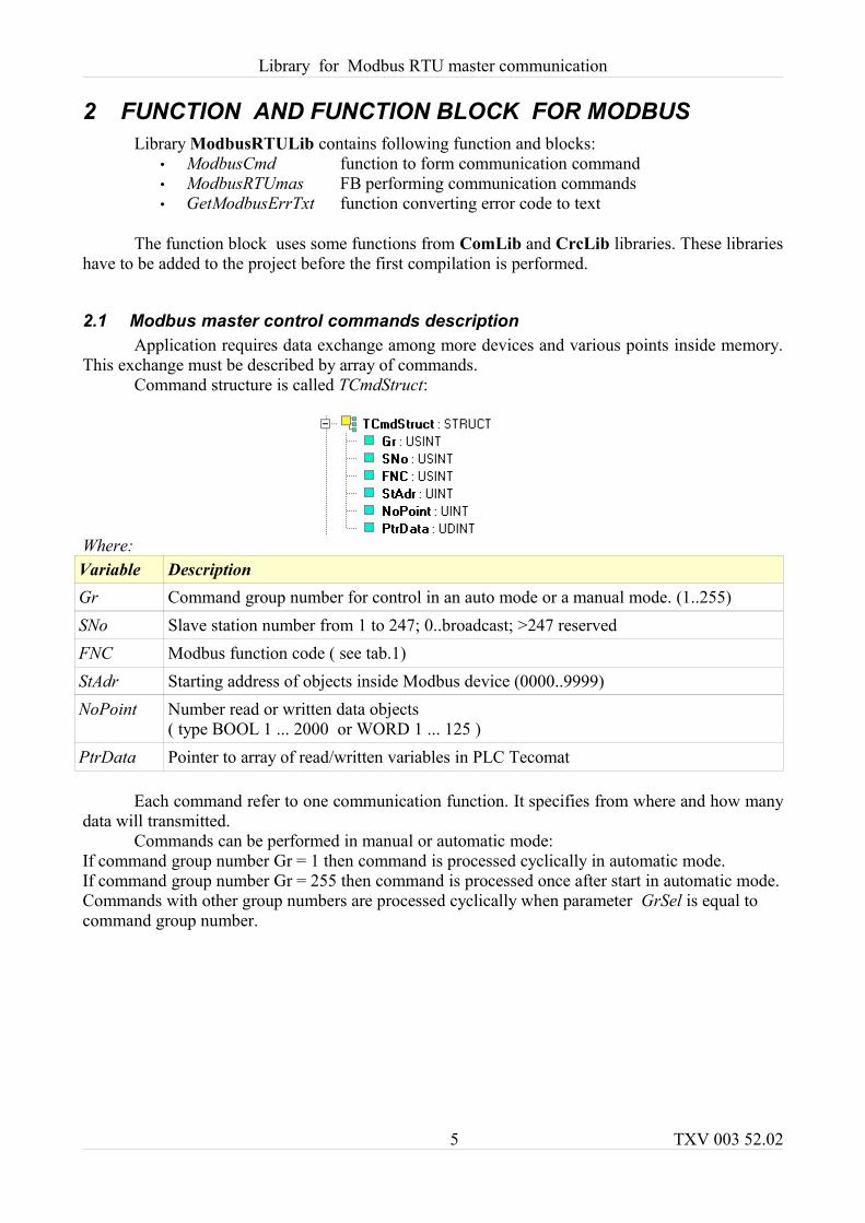
2.1 Modbus master control commands descriptionApplication requires data exchange among more devices and various points inside memory.
This exchange must be described by array of commands.Command structure is called TCmdStruct:
Where:Variable DescriptionGr Command group number for control in an auto mode or a manual mode. (1..255)SNo Slave station number from 1 to 247; 0..broadcast; >247 reservedFNC Modbus function code ( see tab.1)StAdr Starting address of objects inside Modbus device (0000..9999)NoPoint Number read or written data objects
( type BOOL 1 ... 2000 or WORD 1 ... 125 )PtrData Pointer to array of read/written variables in PLC Tecomat
Each command refer to one communication function. It specifies from where and how many data will transmitted.
Commands can be performed in manual or automatic mode: If command group number Gr = 1 then command is processed cyclically in automatic mode. If command group number Gr = 255 then command is processed once after start in automatic mode.Commands with other group numbers are processed cyclically when parameter GrSel is equal to command group number.
5 TXV 003 52.02
Library for Modbus RTU master communication
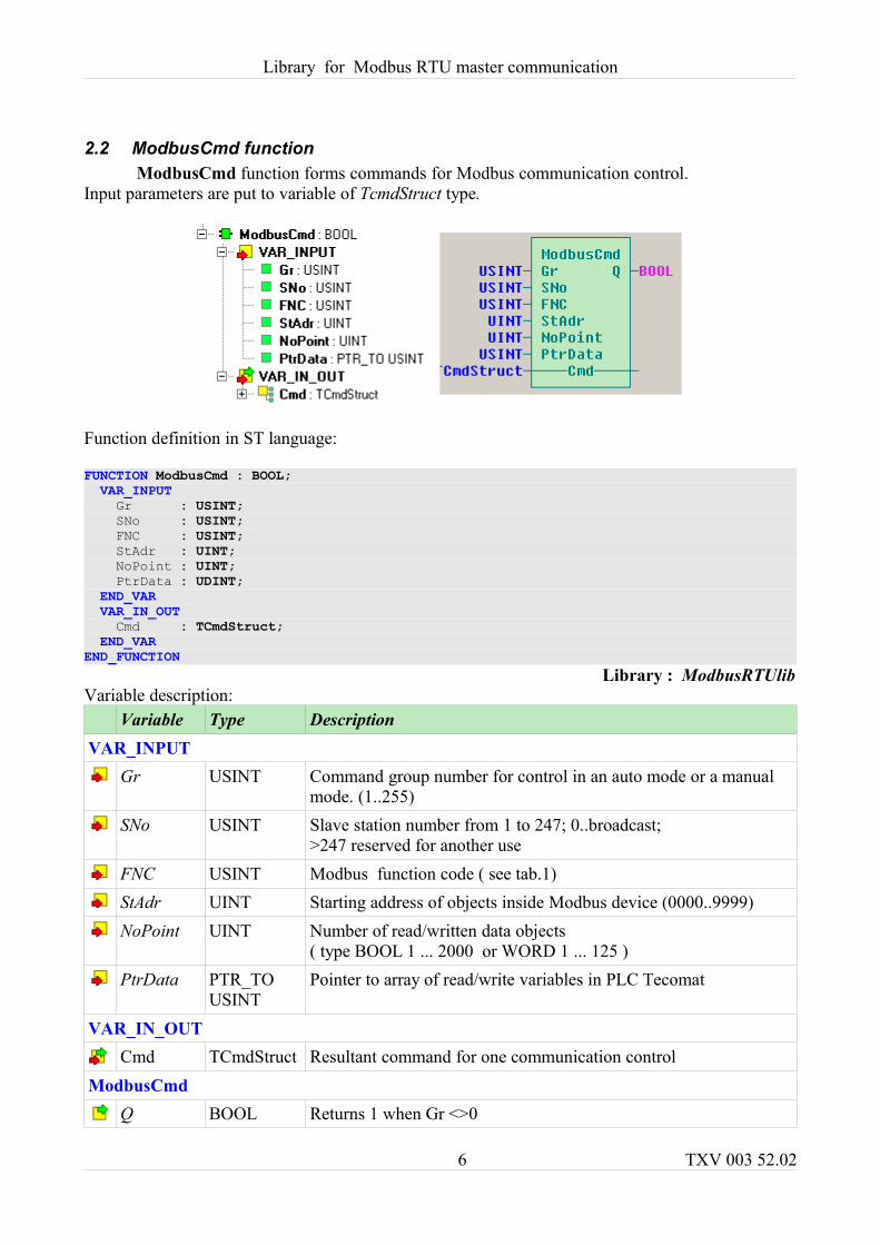
2.2 ModbusCmd functionModbusCmd function forms commands for Modbus communication control.
Input parameters are put to variable of TcmdStruct type.
Function definition in ST language:
FUNCTION ModbusCmd : BOOL; VAR_INPUT Gr : USINT; SNo : USINT; FNC : USINT; StAdr : UINT; NoPoint : UINT; PtrData : UDINT; END_VAR VAR_IN_OUT Cmd : TCmdStruct; END_VAREND_FUNCTION
Library : ModbusRTUlibVariable description:
Variable Type DescriptionVAR_INPUT
Gr USINT Command group number for control in an auto mode or a manual mode. (1..255)
SNo USINT Slave station number from 1 to 247; 0..broadcast; >247 reserved for another use
FNC USINT Modbus function code ( see tab.1)StAdr UINT Starting address of objects inside Modbus device (0000..9999)NoPoint UINT Number of read/written data objects
( type BOOL 1 ... 2000 or WORD 1 ... 125 )PtrData PTR_TO
USINTPointer to array of read/write variables in PLC Tecomat
VAR_IN_OUTCmd TCmdStruct Resultant command for one communication control
ModbusCmdQ BOOL Returns 1 when Gr <>0
6 TXV 003 52.02
Library for Modbus RTU master communication
Example of calling functions in ST language. Two commands are formed for CH2 channel.:
VAR_GLOBAL Temper : REAL; // temperatures Temper1 : REAL; Press : REAL; // pressures Press1 : REAL; Press2 : REAL; CmdCH2 : ARRAY [1..2] OF TCmdStruct; // Array of Modbus commands for CH2 channelEND_VARPROGRAM prgMainModbusCmd(Gr:=1,FNC:=03,SNo:=1,StAdr:=1,NoPoint:=4,PtrData:=adr(Temper),Cmd:=CmdCH2[1]);ModbusCmd(Gr:=1,FNC:=03,SNo:=2,StAdr:=5,NoPoint:=6,PtrData:=adr(Press), Cmd:=CmdCH2[2]);END_PROGRAM
First command will read four words from first object from station number 1 to variable Tem-per in PLC Tecomat by function 03 Read Holding Registers.
Second command will read six words from fifth object from number station 2 to variable Press in PLC Tecomat by function 03 Read Holding Registers. Both commands are written to array commands CmdCH2.Variable are of REAL type. REAL occupies two words therefore parameter NoPoint is twice more than number of variables.
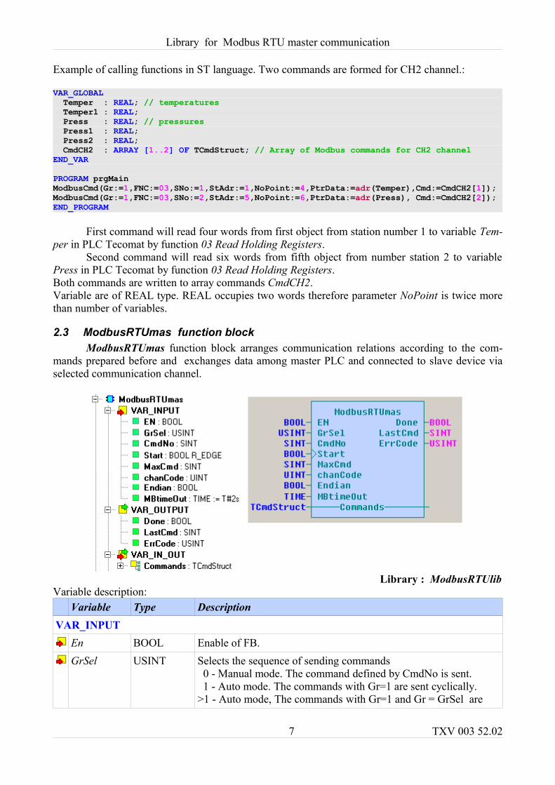
2.3 ModbusRTUmas function blockModbusRTUmas function block arranges communication relations according to the com-
mands prepared before and exchanges data among master PLC and connected to slave device via selected communication channel.
Library : ModbusRTUlibVariable description:
Variable Type DescriptionVAR_INPUT
En BOOL Enable of FB. GrSel USINT Selects the sequence of sending commands
0 - Manual mode. The command defined by CmdNo is sent. 1 - Auto mode. The commands with Gr=1 are sent cyclically.>1 - Auto mode, The commands with Gr=1 and Gr = GrSel are
7 TXV 003 52.02
Library for Modbus RTU master communication
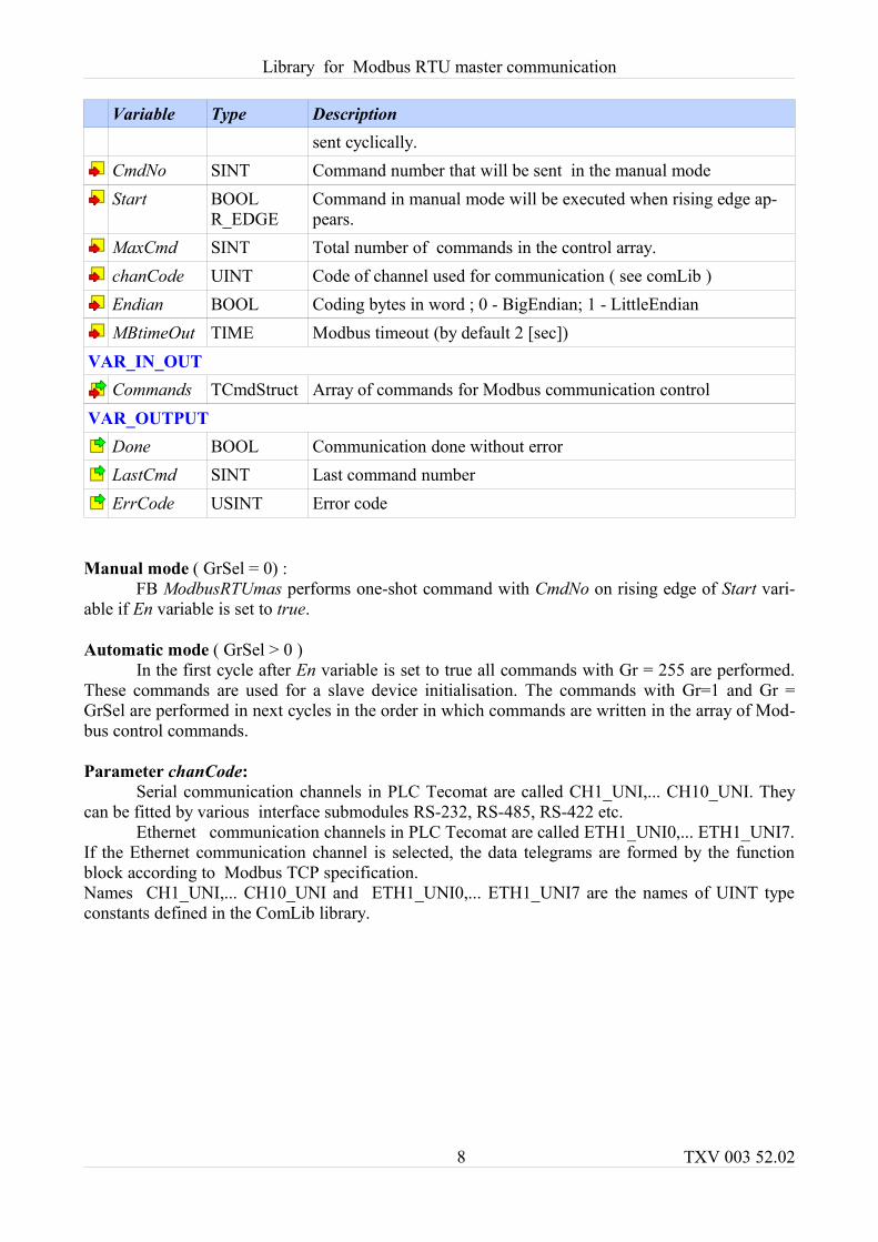
Variable Type Descriptionsent cyclically.
CmdNo SINT Command number that will be sent in the manual modeStart BOOL
R_EDGECommand in manual mode will be executed when rising edge ap-pears.
MaxCmd SINT Total number of commands in the control array.chanCode UINT Code of channel used for communication ( see comLib ) Endian BOOL Coding bytes in word ; 0 - BigEndian; 1 - LittleEndianMBtimeOut TIME Modbus timeout (by default 2 [sec])
VAR_IN_OUTCommands TCmdStruct Array of commands for Modbus communication control
VAR_OUTPUTDone BOOL Communication done without errorLastCmd SINT Last command numberErrCode USINT Error code
Manual mode ( GrSel = 0) : FB ModbusRTUmas performs one-shot command with CmdNo on rising edge of Start vari-
able if En variable is set to true.
Automatic mode ( GrSel > 0 )In the first cycle after En variable is set to true all commands with Gr = 255 are performed.
These commands are used for a slave device initialisation. The commands with Gr=1 and Gr = GrSel are performed in next cycles in the order in which commands are written in the array of Mod-bus control commands.
Parameter chanCode: Serial communication channels in PLC Tecomat are called CH1_UNI,... CH10_UNI. They
can be fitted by various interface submodules RS-232, RS-485, RS-422 etc.Ethernet communication channels in PLC Tecomat are called ETH1_UNI0,... ETH1_UNI7.
If the Ethernet communication channel is selected, the data telegrams are formed by the function block according to Modbus TCP specification.Names CH1_UNI,... CH10_UNI and ETH1_UNI0,... ETH1_UNI7 are the names of UINT type constants defined in the ComLib library.
8 TXV 003 52.02
Library for Modbus RTU master communication
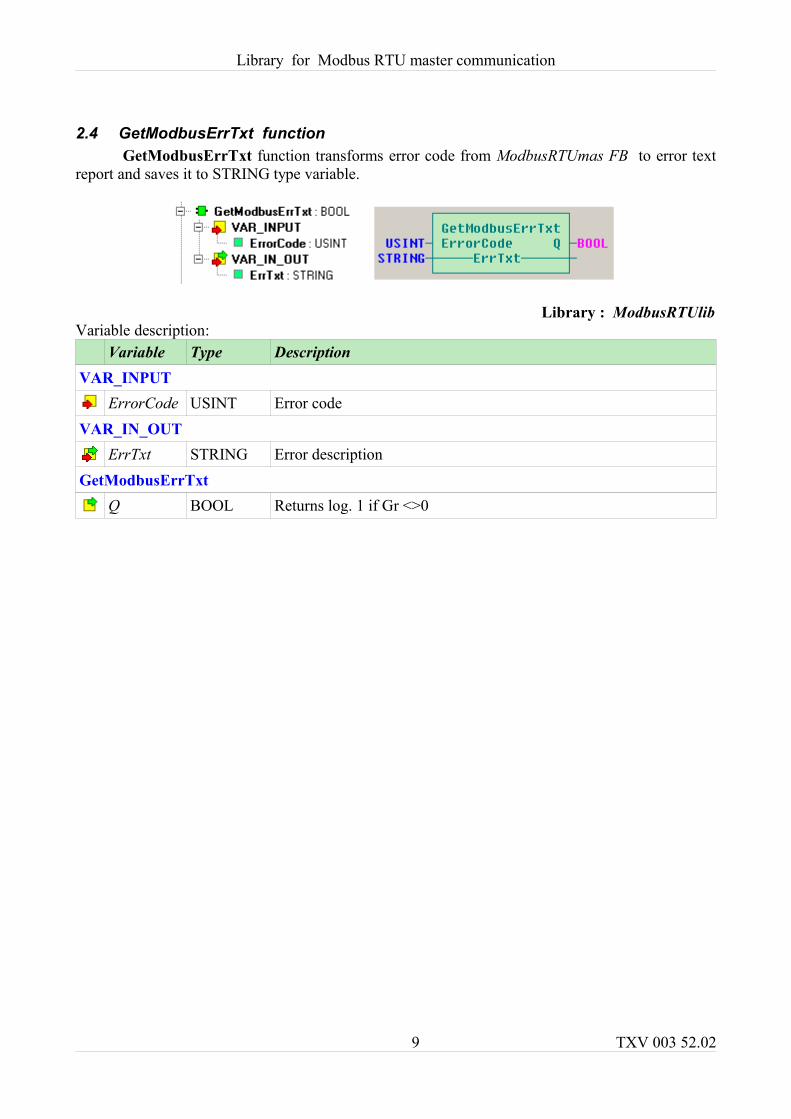
2.4 GetModbusErrTxt functionGetModbusErrTxt function transforms error code from ModbusRTUmas FB to error text
report and saves it to STRING type variable.
Library : ModbusRTUlibVariable description:
Variable Type DescriptionVAR_INPUT
ErrorCode USINT Error codeVAR_IN_OUT
ErrTxt STRING Error description GetModbusErrTxt
Q BOOL Returns log. 1 if Gr <>0
9 TXV 003 52.02
Library for Modbus RTU master communication
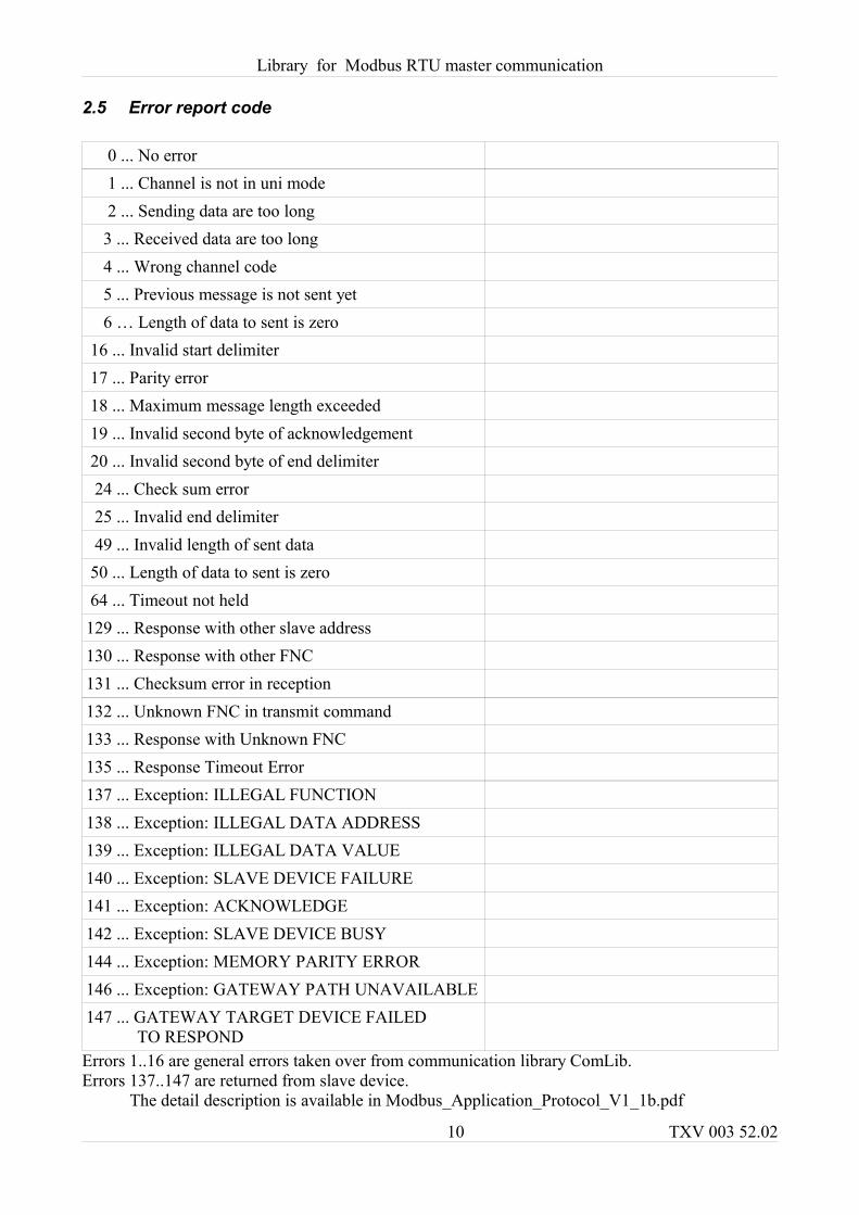
2.5 Error report code
0 ... No error 1 ... Channel is not in uni mode 2 ... Sending data are too long 3 ... Received data are too long 4 ... Wrong channel code 5 ... Previous message is not sent yet 6 … Length of data to sent is zero 16 ... Invalid start delimiter 17 ... Parity error 18 ... Maximum message length exceeded 19 ... Invalid second byte of acknowledgement 20 ... Invalid second byte of end delimiter 24 ... Check sum error 25 ... Invalid end delimiter 49 ... Invalid length of sent data 50 ... Length of data to sent is zero 64 ... Timeout not held 129 ... Response with other slave address 130 ... Response with other FNC131 ... Checksum error in reception 132 ... Unknown FNC in transmit command 133 ... Response with Unknown FNC 135 ... Response Timeout Error 137 ... Exception: ILLEGAL FUNCTION138 ... Exception: ILLEGAL DATA ADDRESS 139 ... Exception: ILLEGAL DATA VALUE 140 ... Exception: SLAVE DEVICE FAILURE 141 ... Exception: ACKNOWLEDGE 142 ... Exception: SLAVE DEVICE BUSY 144 ... Exception: MEMORY PARITY ERROR146 ... Exception: GATEWAY PATH UNAVAILABLE147 ... GATEWAY TARGET DEVICE FAILED
TO RESPOND Errors 1..16 are general errors taken over from communication library ComLib.Errors 137..147 are returned from slave device. The detail description is available in Modbus_Application_Protocol_V1_1b.pdf
10 TXV 003 52.02
Library for Modbus RTU master communication
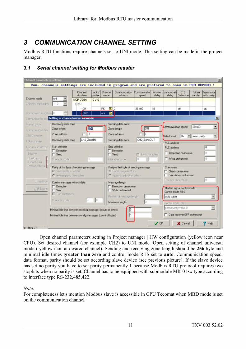
3 COMMUNICATION CHANNEL SETTINGModbus RTU functions require channels set to UNI mode. This setting can be made in the project manager.
3.1 Serial channel setting for Modbus master
Open channel parameters setting in Project manager | HW configuration (yellow icon near CPU). Set desired channel (for example CH2) to UNI mode. Open setting of channel universal mode ( yellow icon at desired channel). Sending and receiving zone length should be 256 byte and minimal idle times greater than zero and control mode RTS set to auto. Communication speed, data format, parity should be set according slave device (see previous picture). If the slave device has set no parity you have to set parity permanently 1 because Modbus RTU protocol requires two stopbits when no parity is set. Channel has to be equipped with submodule MR-01xx type according to interface type RS-232,485,422.
Note: For completeness let's mention Modbus slave is accessible in CPU Tecomat when MBD mode is set on the communication channel.
11 TXV 003 52.02
Library for Modbus RTU master communication
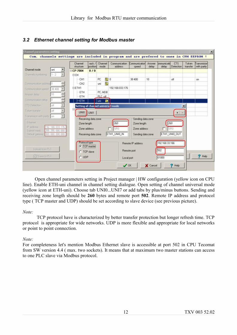
3.2 Ethernet channel setting for Modbus master
Open channel parameters setting in Project manager | HW configuration (yellow icon on CPU line). Enable ETH-uni channel in channel setting dialogue. Open setting of channel universal mode (yellow icon at ETH-uni). Choose tab UNI0...UNI7 or add tabs by plus/minus buttons. Sending and receiving zone length should be 260 bytes and remote port 502. Remote IP address and protocol type ( TCP master and UDP) should be set according to slave device (see previous picture).
Note: TCP protocol have is characterized by better transfer protection but longer refresh time. TCP
protocol is appropriate for wide networks. UDP is more flexible and appropriate for local networks or point to point connection.
Note: For completeness let's mention Modbus Ethernet slave is accessible at port 502 in CPU Tecomat from SW version 4.4 ( max. two sockets). It means that at maximum two master stations can access to one PLC slave via Modbus protocol.
12 TXV 003 52.02
Library for Modbus RTU master communication
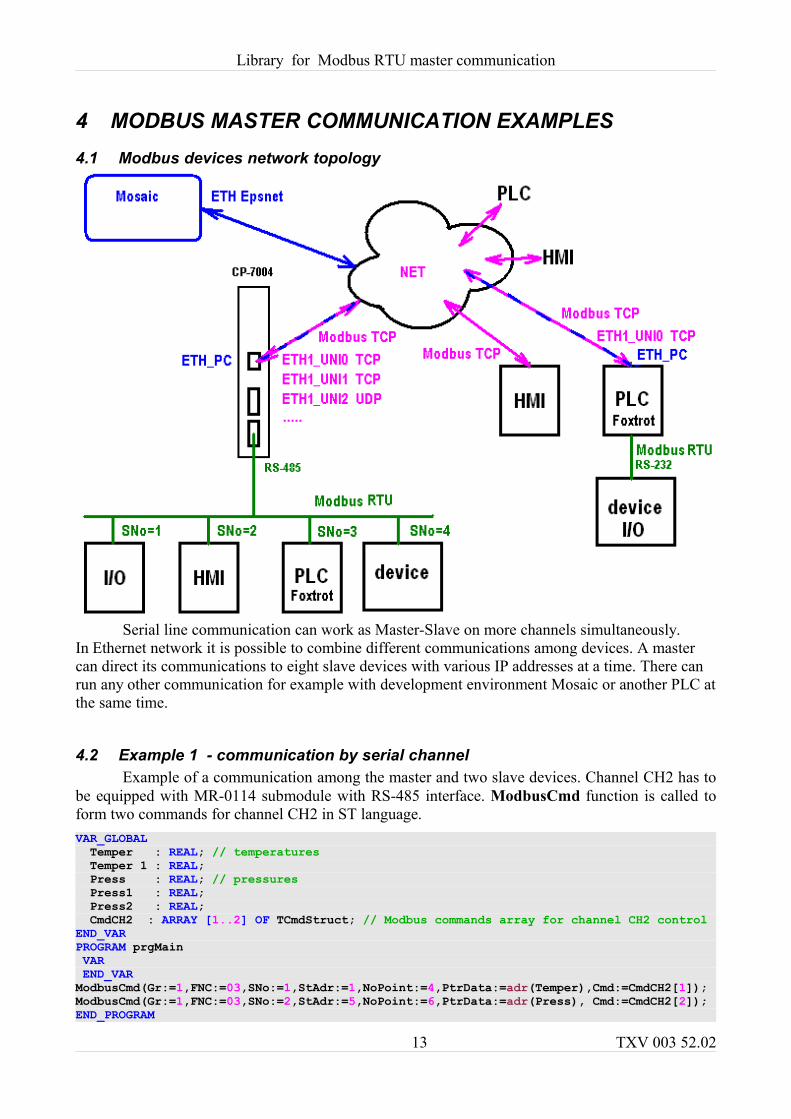
4 MODBUS MASTER COMMUNICATION EXAMPLES4.1 Modbus devices network topology
Serial line communication can work as Master-Slave on more channels simultaneously.In Ethernet network it is possible to combine different communications among devices. A master can direct its communications to eight slave devices with various IP addresses at a time. There can run any other communication for example with development environment Mosaic or another PLC at the same time.
4.2 Example 1 - communication by serial channelExample of a communication among the master and two slave devices. Channel CH2 has to
be equipped with MR-0114 submodule with RS-485 interface. ModbusCmd function is called to form two commands for channel CH2 in ST language.VAR_GLOBAL Temper : REAL; // temperatures Temper 1 : REAL; Press : REAL; // pressures Press1 : REAL; Press2 : REAL; CmdCH2 : ARRAY [1..2] OF TCmdStruct; // Modbus commands array for channel CH2 controlEND_VARPROGRAM prgMain VAR END_VARModbusCmd(Gr:=1,FNC:=03,SNo:=1,StAdr:=1,NoPoint:=4,PtrData:=adr(Temper),Cmd:=CmdCH2[1]);ModbusCmd(Gr:=1,FNC:=03,SNo:=2,StAdr:=5,NoPoint:=6,PtrData:=adr(Press), Cmd:=CmdCH2[2]);END_PROGRAM
13 TXV 003 52.02
Library for Modbus RTU master communication
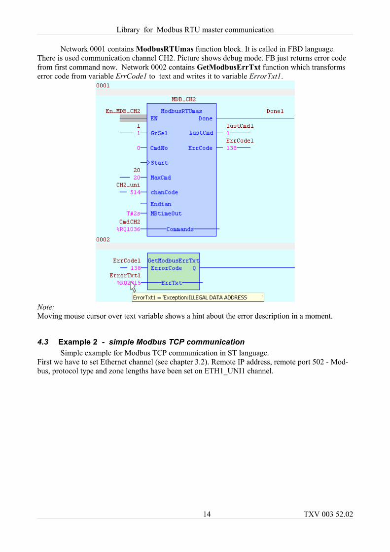
Network 0001 contains ModbusRTUmas function block. It is called in FBD language. There is used communication channel CH2. Picture shows debug mode. FB just returns error code from first command now. Network 0002 contains GetModbusErrTxt function which transforms error code from variable ErrCode1 to text and writes it to variable ErrorTxt1.
Note:Moving mouse cursor over text variable shows a hint about the error description in a moment.
4.3 Example 2 - simple Modbus TCP communicationSimple example for Modbus TCP communication in ST language.
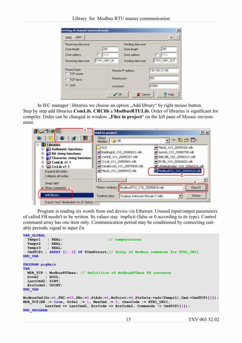
First we have to set Ethernet channel (see chapter 3.2). Remote IP address, remote port 502 - Mod-bus, protocol type and zone lengths have been set on ETH1_UNI1 channel.
14 TXV 003 52.02
Library for Modbus RTU master communication
In IEC manager | libraries we choose an option „Add library“ by right mouse button. Step by step add libraries ComLib, CRClib a ModbusRTULib. Order of libraries is significant for compiler. Order can be changed in window „Files in project“ on the left pane of Mosaic environ-ment.
Program is reading six words from end device via Ethernet. Unused input/output parameters of called FB needn't to be written. Its values stay implicit (false or 0 according to its type). Control command array has one item only. Communication period may be conditioned by connecting suit-able periodic signal to input En.VAR_GLOBAL Tempr1 : REAL; // temperatures Tempr2 : REAL; Tempr3 : REAL; CmdTCP1 : ARRAY [1..2] OF TCmdStruct;// Array of Modbus commands for ETH1_UNI1END_VARPROGRAM prgMainVAR MDB_TCP : ModbusRTUmas; // definition of ModbusRTUmas FB instance Done2 : BOOL; LastCmd2: SINT; ErrCode2: USINT;END_VARModbusCmd(Gr:=1,FNC:=03,SNo:=0,StAdr:=1,NoPoint:=6,PtrData:=adr(Tempr1),Cmd:=CmdTCP1[1]);MDB_TCP(EN := true, GrSel := 1, MaxCmd := 2, chanCode := ETH1_UNI1, LastCmd => LastCmd2, ErrCode => ErrCode2, Commands := CmdTCP1[1]);END_PROGRAM
15 TXV 003 52.02

Library for Modbus RTU master communication
TXV 003 52.02
The manufacturer reserves the right of changes to this documentation. The latest edition of this document is available at www.tecomat.com
16 TXV 003 52.02
For more information please contact:Teco a. s. Havlíčkova 260, 280 58 Kolín 4, Czech Republic tel.: +420 321 737 611, fax: +420 321 737 633, [email protected], www.tecomat.com