liberty® l965e / horizon® hz965e gas fireplace ... · pdf fileto restrict access to a...
TRANSCRIPT
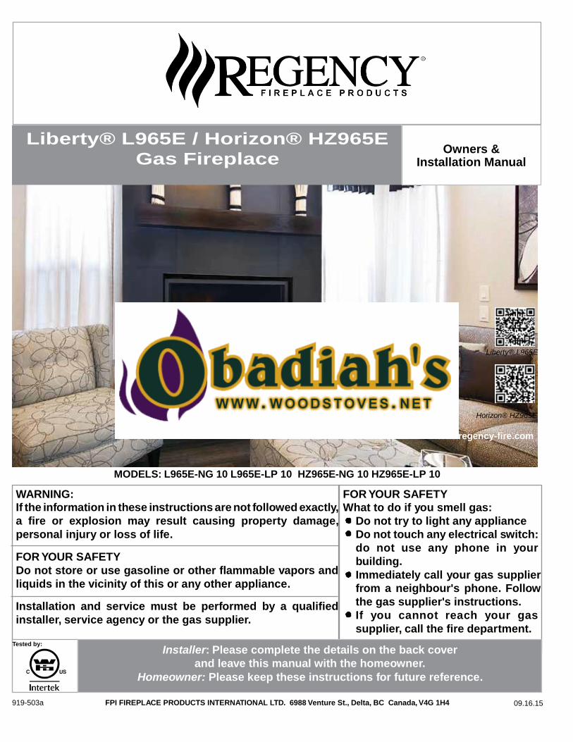
Liberty® L965E / Horizon® HZ965E
Gas Fireplace
Owners & Installation Manual
Liberty® L965E
Horizon® HZ965E
www.regency-fire.com
WARNING:
MODELS: L965E-NG 10 L965E-LP 10 HZ965E-NG 10 HZ965E-LP 10
FOR YOUR SAFETY
If the information in these instructions are not followed exactly,
a fire or explosion may result causing property damage,
personal injury or loss of life.
FOR YOUR SAFETY
Do not store or use gasoline or other flammable vapors and
liquids in the vicinity of this or any other appliance.
Installation and service must be performed by a qualified
installer, service agency or the gas supplier.
What to do if you smell gas:
Do not try to light any appliance
Do not touch any electrical switch:
do not use any phone in your
building.
Immediately call your gas supplier
from a neighbour's phone. Follow
the gas supplier's instructions.
If you cannot reach your gas
supplier, call the fire department.
Tested by:
Installer: Please complete the details on the back cover
and leave this manual with the homeowner.
Homeowner: Please keep these instructions for future reference.
919-503a FPI FIREPLACE PRODUCTS INTERNATIONAL LTD. 6988 Venture St., Delta, BC Canada, V4G 1H4 09.16.15
FOR SAFE INSTALLATION AND OPERATION OF YOUR “Regency” HEATER,
PLEASE CAREFULLY READ THE FOLLOWING INFORMATION:
• All Regency gas-fired appliances must be installed
in accordance with their instructions. Carefully read all
the instructions in this manual first. Consult the building
authority having jurisdiction to determine the need for a
permit prior to commencing the installation.
• NOTE: Failure to follow these instructions could
cause a malfunction of the fireplace, which could result in
death, serious bodily injury, and/or property damage.
• Failure to follow these instructions may also void your
fire insurance and/or warranty.
GENERAL
• Installation and repair should be done by a qualified
service person. The appliance should be inspected
before the first use and, at least, annually by a qualified
service person. More frequent cleaning may be required
due to excessive lint from carpeting, bedding material,
etc. It is imperative the control compartments, burners
and circulating air passageways of the appliance be kept
clean.
• Due to high temperatures, the appliance should be
located out of high traffic areas and away from furniture
and draperies.
Children and adults should be alerted to the hazards
of high surface temperatures and should stay away
to avoid burn or clothing ignition.
• Young children should be carefully supervised when
they are in the same room as the appliance, Toddlers,
young children and others may be susceptible to
accidental contact burns. A physical barrier is
recommended if there are at risk individuals in the house.
To restrict access to a fireplace or stove, install an
adjustable safety gate to keep toddlers, young children
and other at risk individuals out of the room and away
from hot surfaces.
• Clothing or other flammable materials should not be
placed on or near the appliance.
FOR YOUR SAFETY
• Installation and service must be performed by a
qualified installer, service agency or gas supplier.
• This installation must conform to local codes or, in the
absence of local codes, to the current CAN/CSA-B149.1
Natural Gas and Propane Installation Code (Canada) or
National Fuel Gas Code ANSI Z223.1.2 (USA)
• To prevent injury, do not allow anyone who is
unfamiliar with the fireplace to operate it.
• To prevent injury, if the pilot or pilot and burners
have gone out on their own, open the glass door and
wait 5 minutes to air out before attempting to re-light
the fireplace.
• Always keep the area around these appliances clear
of combustible material, gasoline and other flammable
liquids and vapours.
• These appliances should not be used as a drying
rack for clothing or for hanging Christmas stockings/
decorations.
• Due to the paint curing on the fireplace, a faint odor
and slight smoking will likely be noticed when the fireplace
is first used. Open a window until the smoking stops.
Always connect this gas fireplace to a vent system and
vent to the outside of the building envelope. Never vent
to another room or inside the building. Make sure the
specified vent pipe is used, properly sized and of adequate
height to provide sufficient draft. Inspect the venting
system annually for blockage and signs of deterioration.
WARNING: Failure to position the parts in accordance
with the diagrams in this booklet, or failure to use only
parts specifically approved with this appliance, may result
in property damage or personal injury.
WARNING: Do not operate with the glass front removed,
cracked or broken. Replacement of the glass should be
done by a licensed or qualified service person.
• Never use solid fuels such as wood, paper, cardboard,
coal, or any flammable liquids, etc., in this appliance.
• Do not use this heater if any part has been under
water. Immediately call a qualified service technician to
inspect the heater and to replace any part of the control
or gas control systems that have been under water.
• Do not abuse the glass by striking it or slamming the
door shut.
Liberty L965E Horizon HZ965E
Dimensions: 5 START-UP & OPERATION 52
Rating Label Location: 5 Normal Sounds During Operation: 52
Copy of the safety label 6 Remote Control Operations: 52
INSTALLATION 7 Technical Data 52
Introduction: 7 System Description: 52
Non-Combustible Material Zone: 7 Wall Mounting The Receiver: 54
Framing: 8 Operating Procedure: 54
Internal chase: 8 Smart Thermostat (Transmitter Operation) 55
External chase: 9 Remote Flame Control 55
Corner framing: 10 Remote Actuated Accent Lights 55
Framing for sidewalls and mantel: 11 Key lock 56
Typical Framing - Raised Hearth: 12 Low Battery Power Detection 56
Installation of Fireplace Facing: 13 Manual Bypass Of The Remote System 56
Receiver installation 14 Split Valve Operation 56
Allowable vent configurations: 15 Air Shutter Adjustment: 57
Vent Termination Restrictions: 16 Diagnostic flash codes: 57
Approved Vent Parts: 17 Wiring Harness 58
Installation of Flue Restrictor: 18 Air Intake: 59
TV Installation Above Unit: 19 Lighting Instruction Label: 59
Planning Your Installation: 20 Light Bulb Replacement 60
Assembly of the Unit: 20 CLEANING / ANNUAL SERVICE 60
Securing unit into Position: 20 Cleaning The Glass: 60
Installation Of Non-combustible Wall And Hearth Board: 21 Replacing Glass: 60
Installation Of Venting And Terminations: 21 Burner & Firebox Cleaning: 60
Horizontal Installation: 22
Vertical Termination Installation: 23
Heat Distribution Kit installation 26
Power vent Kit installation 30
Door Removal and Installation: 38
Gas Hook-Up: 39
Electrical Hook-Up: 39
LP Gas Conversion: 40
Glass Burner Removal/installation: 43
Glass Crystal installation : 44
Optional Spa Stones Installation 44
Reflective panel installation / Removal: 45
TROUBLESHOOTING 61
Appendix A - Optional Reduced Ceiling Height Installation 63
Warranty 66
Brick panel installation / Removal: 46
Log Burner / Ember Bed removal / Installation 47
Log set installation: 47
Safety screen Installation 50
Finishing trim: 51
Liberty Gas Inserts Benefits
Horizon Gas Inserts Benefits
DIRECT VENT ONLY: This type is identified by the prefix DV. This appliance draws all of its air for combustion from outside
the dwelling, through a specially designed vent pipe system.
This appliance has been tested and approved for installations from 0 feet to 4500 feet (1372 m) above sea level.
In the USA: The appliance may be installed at higher altitudes. Please refer to your American Gas Association guidelines
which state: the sea level rated input of Gas Designed Appliances installed at elevations above 2000 (610 m) feet is to be
reduced 4% for each 1000 feet (305 m) above sea level. Refer also to National Fuel Gas Code, ANSI Z223.1/ NFPA 54,
local authorities, or codes which have jurisdiction in your area regarding the de-rate guidelines.
In Canada: When the appliance is installed at elevations above 4500 feet (1372 m), the certified high altitude rating shall
be reduced at the rate of 4% for each additional 1000 feet (305 m). Refer also to CSA-B149.1 Natural Gas and Propane
Installation Code, local authorities, or codes which have jurisdiction in your area regarding the de-rate guidelines.
• This appliance has been tested by INTERTEK TESTING SERVICES NA LTD. and found to comply with the established
VENTED GAS FIREPLACE HEATER standards in CANADA and the USA as follows:
VENTED GAS FIREPLACE HEATER (L965E/HZ965E; NG/LPG)
TESTED TO: ANSI Z21.88-2014/CSA 2.33-2014 VENTED GAS FIREPLACE HEATERS
CAN/CGA 2.17-M91 GAS FIRED APPLIANCES FOR HIGH ALTITUDES
CSA P.4.1-02 TESTING METHOD FOR MEASURING ANNUAL FIREPLACE EFFICIENCY
This Regency L965E/HZ965E Fireplace:
• Has been certified for use with either natural or propane gases. (See rating label.)
• Is not for use with solid fuels.
• Is approved for bedroom or bed sitting room. (IN CANADA: must be installed with a listed wall
thermostat. IN USA: see current ANSI Z223.1 for installation instructions.)
• Must be installed in accordance with local codes. If none exist, use current installation code CAN/
CSA-B149.1 Natural Gas and Propane Installation Code (Canada in Canada or ANSI Z223.1/NFPA
54 in the USA.
• Must be properly connected to an approved venting system and not connected to a chimney flue
serving a separate solid-fuel burning appliance.
• The flow of combustion and ventilation air not be obstructed.
IMPORTANT NOTICE (Regarding first fire up):
When the unit is turned on for the first time, it should be turned onto high without the fan on for
the first 4 hours. This will cure the paint, logs, gasket material and other products used in the
manufacturing process. It is advisable to open a window or door, as the unit will start to smoke and
can irritate some people. After the unit has gone through the first burn, turn the unit off including
the pilot, let the unit get cold then remove the glass door and clean it with a good gas fireplace
glass cleaner, available at your local Regency dealer.
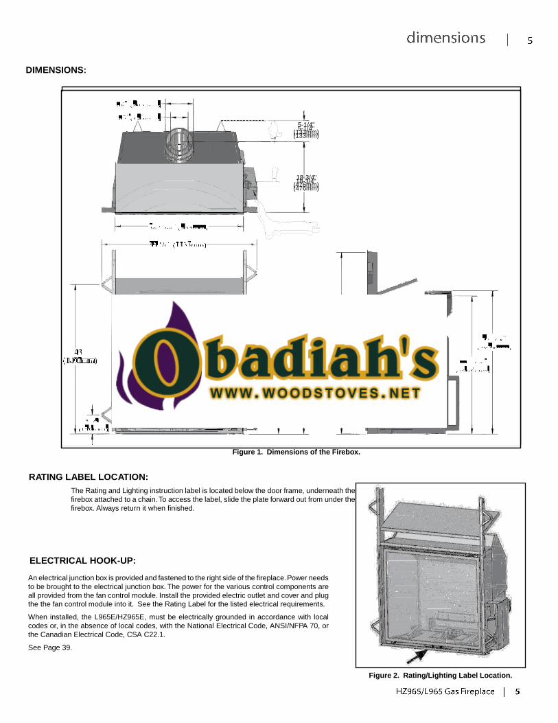
DIMENSIONS:
5-1/4" 5-1/4"
(133mm) (133mm)
18-3/4" 18-3/4"
(476mm) (476mm)
52-5/16" 52-5/16"
(1329mm) (1329mm)
Figure 1. Dimensions of the Firebox.
RATING LABEL LOCATION:
The Rating and Lighting instruction label is located below the door frame, underneath the
firebox attached to a chain. To access the label, slide the plate forward out from under the
firebox. Always return it when finished.
ELECTRICAL HOOK-UP:
An electrical junction box is provided and fastened to the right side of the fireplace. Power needs
to be brought to the electrical junction box. The power for the various control components are
all provided from the fan control module. Install the provided electric outlet and cover and plug
the the fan control module into it. See the Rating Label for the listed electrical requirements.
When installed, the L965E/HZ965E, must be electrically grounded in accordance with local
codes or, in the absence of local codes, with the National Electrical Code, ANSI/NFPA 70, or
the Canadian Electrical Code, CSA C22.1.
See Page 39.
Figure 2. Rating/Lighting Label Location.
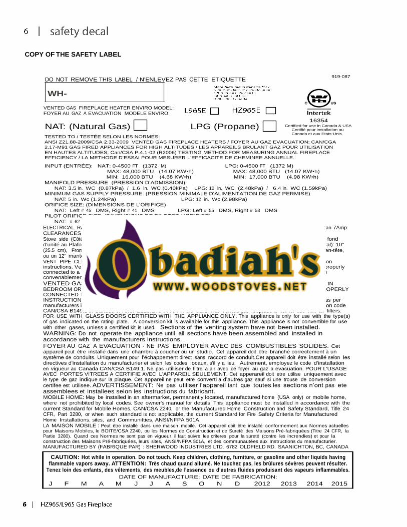
COPY OF THE SAFETY LABEL
DO NOT REMOVE THIS LABEL / N'ENLEVEZ PAS CETTE ETIQUETTE 919-087
WH-
VENTED GAS FIREPLACE HEATER ENVIRO MODEL: FOYER AU GAZ A EVACUATION MODELE ENVIRO:
16354
NAT: (Natural Gas) LPG (Propane)
TESTED TO / TESTÉE SELON LES NORMES:
Certified for use in Canada & USA
Certifié pour installation au
Canada et aux Etats-Unis.
ANSI Z21.88-2009/CSA 2.33-2009 VENTED GAS FIREPLACE HEATERS / FOYER AU GAZ EVACUATION; CAN/CGA
2.17-M91 GAS FIRED APPLIANCES FOR HIGH ALTITUDES / LES APPAREILS BRULANT GAZ POUR UTILISATION
EN HAUTES ALTITUDES; Can/CSA P.4.1-02 (R2006) TESTING METHOD FOR MEASURING ANNUAL FIREPLACE
EFFICIENCY / LA METHODE D'ESSAI POUR MESURER L'EFFICACITE DE CHEMINEE ANNUELLE.
INPUT (ENTRÉE): NAT: 0-4500 FT (1372 M) LPG: 0-4500 FT (1372 M)
MAX: 48,000 BTU (14.07 KW•h) MAX: 48,000 BTU (14.07 KW•h)
MIN: 16,000 BTU (4.68 KW•h) MIN: 17,000 BTU (4.98 KW•h)
MANIFOLD PRESSURE (PRESSION D’ADMISSION):
NAT: 3.5 in. WC (0.87kPa) / 1.6 in. WC (0.40kPa) LPG: 10 in. WC (2.48kPa) / 6.4 in. WC (1.59kPa)
MINIMUM GAS SUPPLY PRESSURE: (PRESSION MINIMALE D'ALIMENTATION DE GAZ PERMISE)
NAT: 5 in. Wc (1.24kPa) LPG: 12 in. Wc (2.98kPa)
ORIFICE SIZE: (DIMENSIONS DE L’ORIFICE)
NAT: Left # 45 DMS, Right # 41 DMS LPG: Left # 55 DMS, Right # 53 DMS
PILOT ORIFICE SIZE: (DIMENSIONS DE PILOTER L’ORIFICE)
NAT: # 62 DMS LPG: Left # 35 DMS
ELECTRICAL RATING:(EXIGENCES ÉLECTRIQUES) Fan type circulator (Ventilateur circulaire): 120V AC 60hz/ Less than 7Amp CLEARANCES TO COMBUSTIBLES: (DISTANCE OBLIGATOIRE DES COMBUSTIBLES) Stove side (Côté de poêle): 4 inches (10.2cm), Back (Arriére): 4 inches (10.2cm), Ceiling from bottom of unit (Du fond d'unité au Plafond): 80” inches (203.2cm), From fireplace frame to side wall (Du frome de la cheminée au mur latéral): 10" (25.5 cm), From base of the unit to shelf, header, or 12" (30.5cm) mantel (De la base de l'unité à une étagère, un en-tête, ou un 12" manteau de cheminée): 52.25" (133cm) VENT PIPE CLEARANCES:(ESPACES LIBRES DE VENTILATION) See manufacturer’s listing, label and installation instructions. Verifeez l’identifaction, l’etiquette et les instructionsd’installation du fabricant. This appliance must be properly connected to a venting system in accordance with the manufacturer's installation instructions. Cet appareil doit être convenablement connecté à un système donner vent conformément aux instructions d'installation du fabricant.
VENTED GAS FIREPLACE HEATER - NOT FOR USE WITH SOLID FUELS. MAY BE INSTALLED IN BEDROOM OR BEDSITTING ROOM (IN CANADA with a listed wall thermostat). THIS APPLIANCE MUST BE PROPERLY CONNECTED TO A VENTING SYSTEM IN ACCORDANCE WITH THE MANUFACTURER'S INSTALLATION INSTRUCTIONS. FOR DIRECT DISCHARGE WITHOUT DUCT CONNECTION. This appliance must be installed as per manufacturers installation instructions and in accordance with local codes if any. If none exist, use current installation code CAN/CSA B149.1 in Canada or ANSI Z223.1/NFPA 54 in the USA. This vented gas fireplace is not for use with air filters. FOR USE WITH GLASS DOORS CERTIFIED WITH THE APPLIANCE ONLY. This appliance is only for use with the type(s) of gas indicated on the rating plate. A conversion kit is available for this appliance. This appliance is not convertible for use
with other gases, unless a certified kit is used. Sections of the venting system have not been installed. WARNING: Do not operate the appliance until all sections have been assembled and installed in accordance with the manufacturers instructions. FOYER AU GAZ A EVACUATION - NE PAS EMPLOYER AVEC DES COMBUSTIBLES SOLIDES. Cet appareil peut être installé dans une chambre à coucher ou un studio. Cet appareil doit être branché correctement à un système de conduits. Uniquement pour l'échappement direct sans raccord de conduit.Cet appareil doit être installé selon les directives d'installation du manufacturier et selon les codes locaux, s'il y a lieu. Autrement, employez le code d'installation en vigueur au Canada CAN/CSA B149.1. Ne pas utilliser de filtre a air avec ce foyer au gaz a evacuation. POUR L'USAGE AVEC PORTES VITREES A CERTIFIE AVEC L'APPAREIL SEULEMENT. Cet apperareil doit etre utilise uniquement avec le type de gaz indique sur la plaque. Cet appareil ne peut etre converti a d’autres gaz sauf si une trouse de conversion
certifee est utilisee. ADVERTISSEMENT: Ne pas utiliser l’appareil tant que toutes les sections n’ont pas ete assemblees et installees selon les instructions du fabricant. MOBILE HOME: May be installed in an aftermarket, permanently located, manufactured home (USA only) or mobile home, where not prohibited by local codes. See owner's manual for details. This appliance must be installed in accordance with the current Standard for Mobile Homes, CAN/CSA Z240, or the Manufactured Home Construction and Safety Standard, Title 24 CFR, Part 3280, or when such standard is not applicable, the current Standard for Fire Safety Criteria for Manufactured Home Installations, sites, and Communitties, ANSI/NFPA 501A. LA MAISON MOBILE : Peut être installé dans une maison mobile. Cet appareil doit être installé conformement aux Normes actuelles pour Maisons Mobiles, le BOITE/CSA Z240, ou les Normes de Construction et de Sureté des Maisons Pré-fabriquées (Titre 24 CFR, la Partie 3280). Quand ces Normes ne sont pas en vigueur, il faut suivre les criteres pour la sureté (contre les increndies) et pour la construction des Maisons Pré-fabriquées, leurs sites, ANSI/NFPA 501A, et des communautées aux Instructions du manufacturier.
MANUFACTURED BY (FABRIQUE PAR) : SHERWOOD INDUSTRIES LTD. 6782 OLDFIELD RD. SAANICHTON, BC, CANADA
CAUTION: Hot while in operation. Do not touch. Keep children, clothing, furniture, or gasoline and other liquids having flammable vapors away. ATTENTION: Très chaud quand allumé. Ne touchez pas, les brûlures sévères peuvent résulter.
Tenez loin des enfants, des vêtements, des meubles,de l’essence ou d’autres fluides produisant des vapeurs inflammables.
DATE OF MANUFACTURE: DATE DE FABRICATION:
J F M A M J J A S O N D 2012 2013 2014 2015
INTRODUCTION:
PLANNING YOUR INSTALLATION
This section of the technical manual is for the use of qualified technicians only. Fireplace placement, hearths, facings, mantles, and venting terminations will
be covered, as well as the gas and electric systems. There are several installation safety guidelines that must be adhered to. Please carefully read the safety
precautions at the front of this manual.
Warning: Clearances must be sufficient to allow access for maintenance and service.
If installing a Power Vent Kit (706-922) or a Heat Distribution Kit (706-921), refer to the instructions included with the kits to aid in your planning.
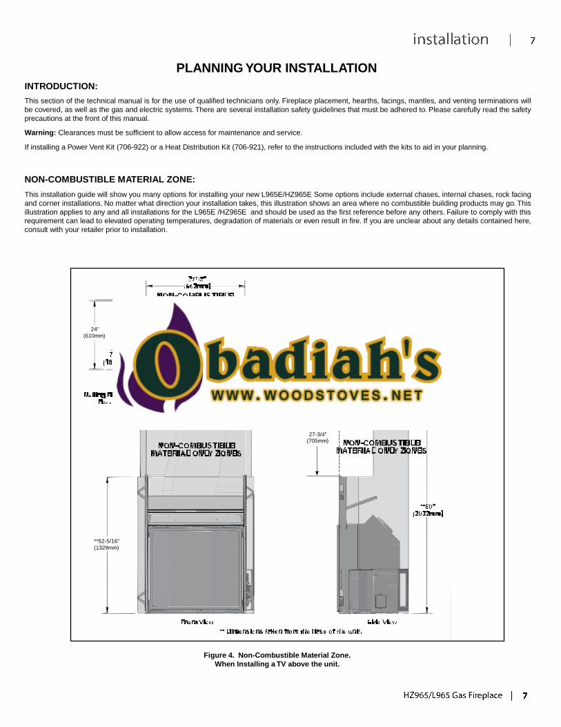
NON-COMBUSTIBLE MATERIAL ZONE:
This installation guide will show you many options for installing your new L965E/HZ965E Some options include external chases, internal chases, rock facing
and corner installations. No matter what direction your installation takes, this illustration shows an area where no combustible building products may go. This
illustration applies to any and all installations for the L965E /HZ965E and should be used as the first reference before any others. Failure to comply with this
requirement can lead to elevated operating temperatures, degradation of materials or even result in fire. If you are unclear about any details contained here,
consult with your retailer prior to installation.
24"
(610mm)
11 "
(279mm)
27-3/4"
(705mm)
**52-5/16"
(1329mm)
Figure 4. Non-Combustible Material Zone.
When Installing a TV above the unit.
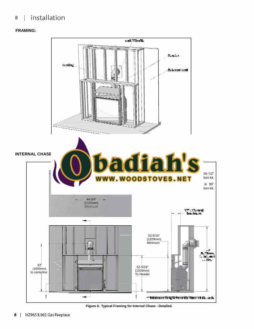
FRAMING:
Figure 5. Typical Framing for Internal Chase - General.
INTERNAL CHASE:
24"
(610mm) Min. Chase Depth
NOTE:
Framing chase depth is 26-1/2”
when using the heat distribution kit.
Internal ceiling clearance is 90”
when using the heat distribution kit.
44-3/4"
(1137mm) Minimum
52-5/16" (1329mm) Minimum
63" (1600mm)
to centerline
52-5/16"
(1329mm) To Header
Figure 6. Typical Framing for Internal Chase - Detailed.
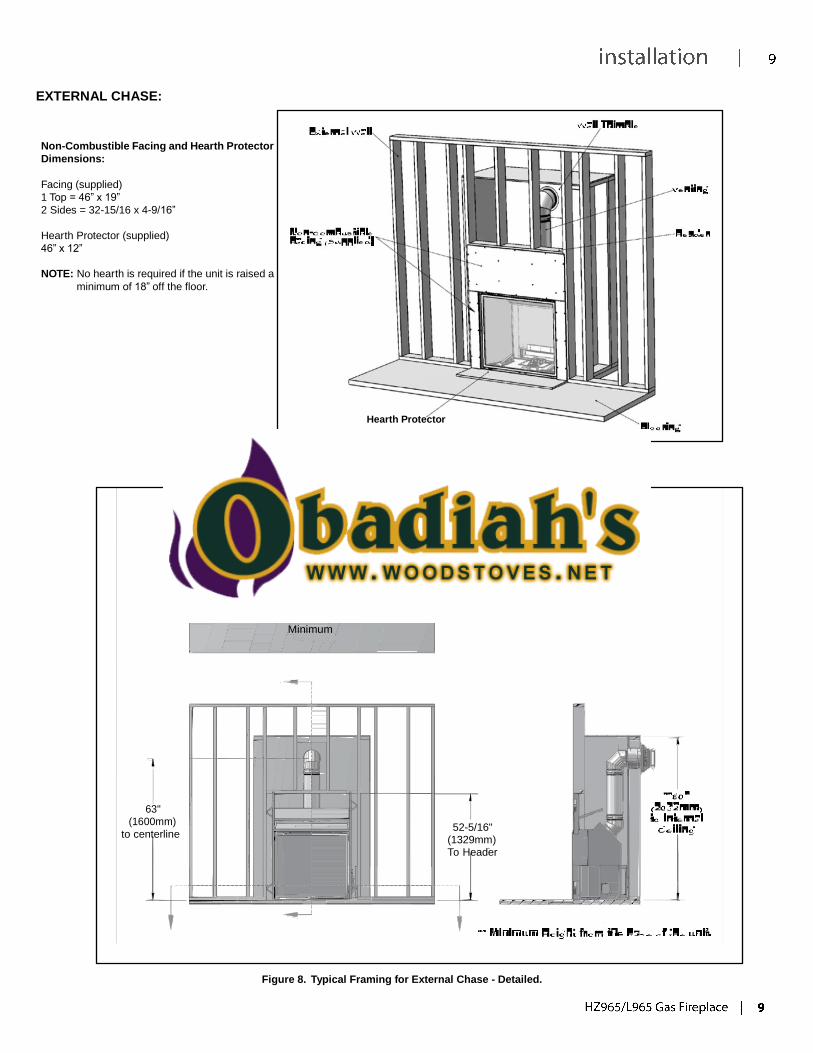
EXTERNAL CHASE:
Non-Combustible Facing and Hearth Protector
Dimensions:
Facing (supplied)
1 Top = 46” x 19”
2 Sides = 32-15/16 x 4-9/16”
Hearth Protector (supplied)
46” x 12”
NOTE: No hearth is required if the unit is raised a
minimum of 18” off the floor.
Hearth Protector
Figure 7. Typical Framing for External Chase - General.
24" (610mm)
Min. Chase Depth
44-3/4" (1137mm) Minimum
63"
(1600mm)
to centerline
52-5/16"
(1329mm) To Header
Figure 8. Typical Framing for External Chase - Detailed.
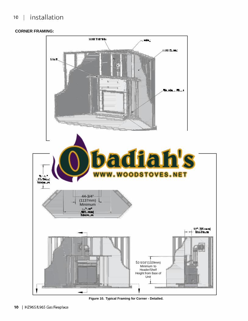
CORNER FRAMING:
Figure 9. Typical Framing for Corner - General.
44-3/4" (1137mm) Minimum
52-5/16"(1329mm)
Minimum to Header/Shelf
Height from Base of Unit
Figure 10. Typical Framing for Corner - Detailed.
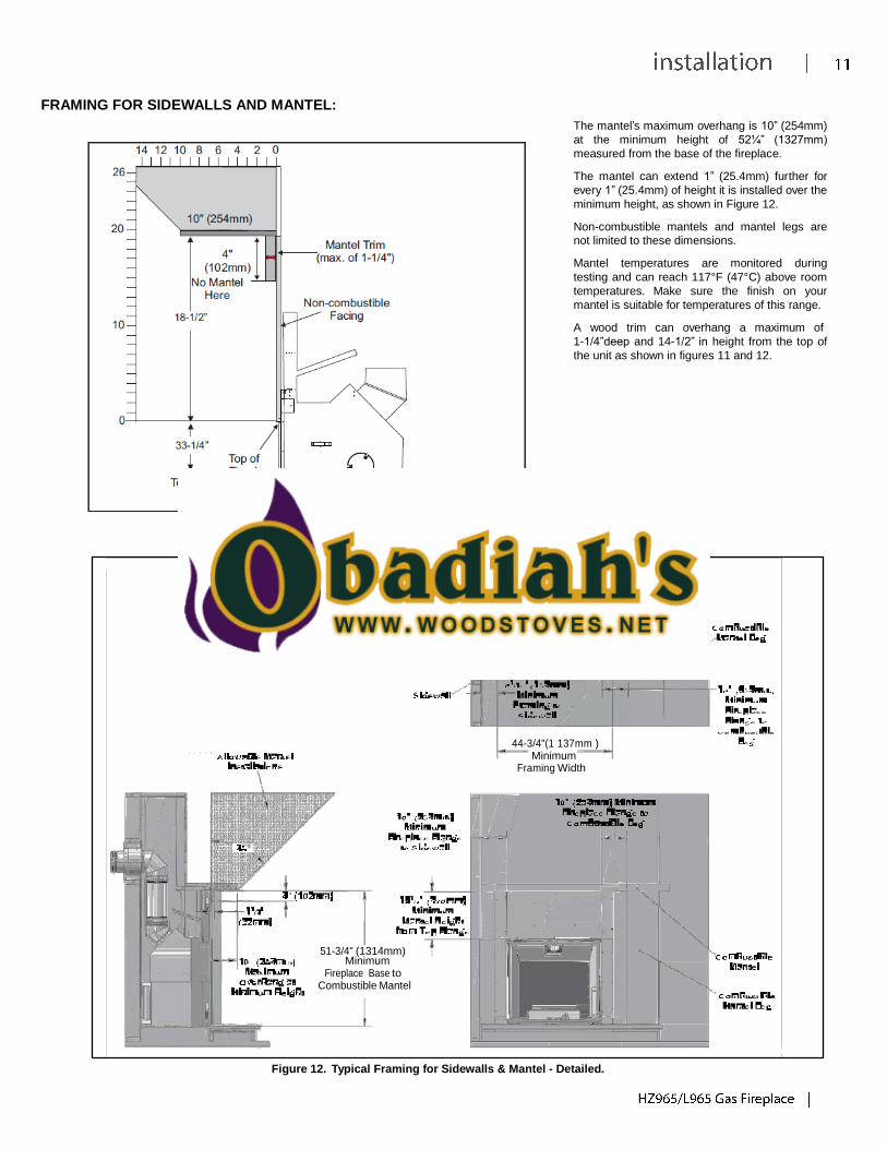
FRAMING FOR SIDEWALLS AND MANTEL:
Figure 11. Mantel Clearances
The mantel’s maximum overhang is 10” (254mm)
at the minimum height of 52¼” (1327mm)
measured from the base of the fireplace.
The mantel can extend 1” (25.4mm) further for
every 1” (25.4mm) of height it is installed over the
minimum height, as shown in Figure 12.
Non-combustible mantels and mantel legs are
not limited to these dimensions.
Mantel temperatures are monitored during
testing and can reach 117°F (47°C) above room
temperatures. Make sure the finish on your
mantel is suitable for temperatures of this range.
A wood trim can overhang a maximum of
1-1/4”deep and 14-1/2” in height from the top of
the unit as shown in figures 11 and 12.
44-3/4"(1 137mm )
Minimum Framing Width
51-3/4" (1314mm) Minimum
Fireplace Base to Combustible Mantel
Figure 12. Typical Framing for Sidewalls & Mantel - Detailed.
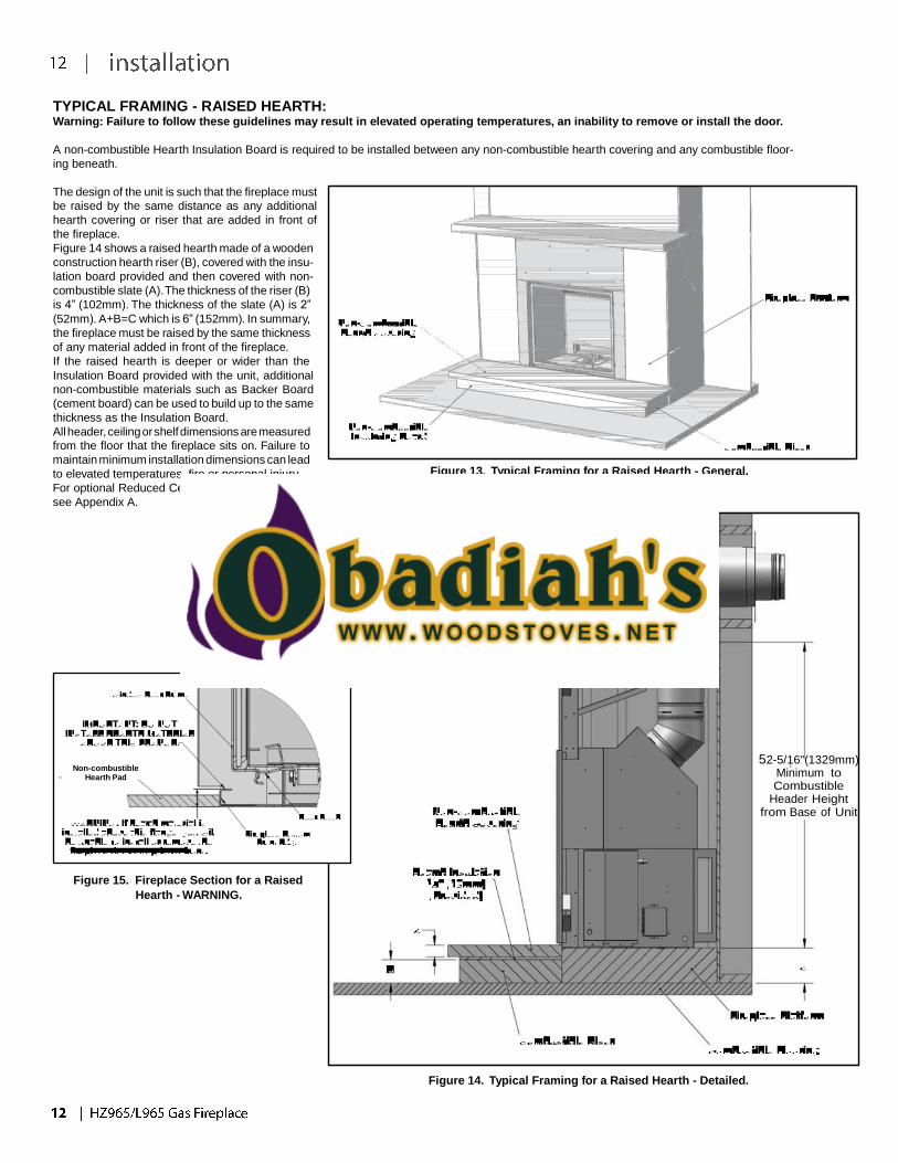
TYPICAL FRAMING - RAISED HEARTH: Warning: Failure to follow these guidelines may result in elevated operating temperatures, an inability to remove or install the door.
A non-combustible Hearth Insulation Board is required to be installed between any non-combustible hearth covering and any combustible floor-
ing beneath.
The design of the unit is such that the fireplace must
be raised by the same distance as any additional
hearth covering or riser that are added in front of
the fireplace.
Figure 14 shows a raised hearth made of a wooden
construction hearth riser (B), covered with the insu-
lation board provided and then covered with non-
combustible slate (A). The thickness of the riser (B)
is 4” (102mm). The thickness of the slate (A) is 2”
(52mm). A+B=C which is 6” (152mm). In summary,
the fireplace must be raised by the same thickness
of any material added in front of the fireplace.
If the raised hearth is deeper or wider than the
Insulation Board provided with the unit, additional
non-combustible materials such as Backer Board
(cement board) can be used to build up to the same
thickness as the Insulation Board.
All header, ceiling or shelf dimensions are measured
from the floor that the fireplace sits on. Failure to
maintain minimum installation dimensions can lead
to elevated temperatures, fire or personal injury.
For optional Reduced Ceiling Height installations,
see Appendix A.
Figure 13. Typical Framing for a Raised Hearth - General.
The insulation board supplied with
this unit is 46”width x 12” depth x 1/2”
thick.
Any additional material such as
marble must be the same width and
depth as the insulation board.
Non-combustible Hearth Pad
Figure 15. Fireplace Section for a Raised
Hearth - WARNING.
52-5/16"(1329mm) Minimum to Combustible
Header Height from Base of Unit
Figure 14. Typical Framing for a Raised Hearth - Detailed.
(Supplied)
(Supplied)
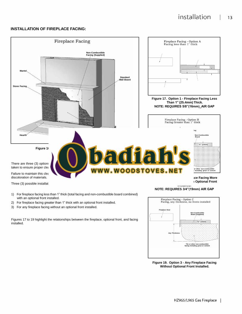
INSTALLATION OF FIREPLACE FACING:
Non-Combustible Facing (Supplied)
Fireplace Door Non-Combustible Board
Mantel
Standard
Wall Board
5/8” (16mm) Minimum Air Gap
1/2” (13mm)
1/2” (13mm)
Stone Facing
Optional Fronts
Tile or other non-combustible facing including grout or cem
Figure 17. Option 1 - Fireplace Facing Less
Than 1” (25.4mm) Thick.
NOTE: REQUIRES 5/8”(16mm)_AIR GAP
Hearth
Fireplace
Door
Fireplace Door Optional Edging
(Supplied)
Non-Combustible Board
1/2” (13mm)
Figure 16. Typical Facing for the Fireplace - General.
There are three (3) options for installing facing to your fireplace installation. Care must be
taken to ensure proper clearances are maintained.
Optional Fronts 3/4” (19mm)
Minimum Air Gap
Tile or other non-combustible
Failure to maintain this clearance will lead to elevated operating temperatures and possible
discoloration of materials.
Three (3) possible installations include:
1) For fireplace facing less than 1” thick (total facing and non-combustible board combined)
with an optional front installed.
2) For fireplace facing greater than 1” thick with an optional front installed.
3) For any fireplace facing without an optional front installed.
facing including grout or cement
Figure 18. Option 2 - Fireplace Facing More
Than 1” (25.4mm) Thick With Optional Front
Installed.
NOTE: REQUIRES 3/4”(19mm) AIR GAP
Fireplace Door
Figures 17 to 19 highlight the relationships between the fireplace, optional front, and facing
installed.
Non-Combustible Board (Supplied)
1/2” (13mm)
Any Thickness
Tile or other non-combustible facing including grout or cement
Figure 19. Option 3 - Any Fireplace Facing
Without Optional Front Installed.
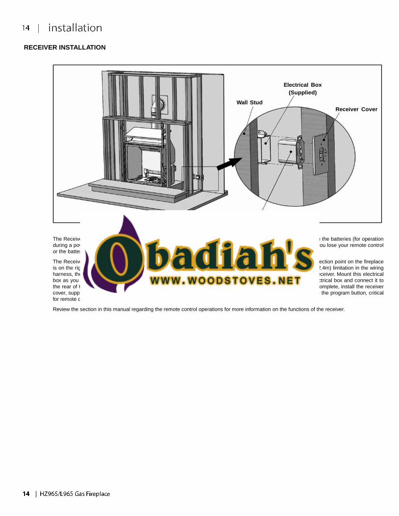
RECEIVER INSTALLATION
Wall Stud
Electrical Box
(Supplied)
Receiver Cover
Receiver
Figure 22. Receiver Installation.
The Receiver is the heart of the remote control system. You need to access this receiver after installation to change the batteries (for operation
during a power failure), to program a new remote / receiver combination and to operate a manual override should you lose your remote control
or the batteries in the remote control lose their power.
The Receiver is connected to the fireplace with a wire harness that has a maximum length of 8 ft (2.4m). The connection point on the fireplace
is on the right side of the unit, where the gas valve and electronic ignition module is located. Because of the 8 ft (2.4m) limitation in the wiring
harness, the receiver needs to be mounted to the right side of the fireplace. An electrical box is provided for the receiver. Mount this electrical
box as you would any electrical outlet or switch box. Thread the cable and connector through the back of the electrical box and connect it to
the rear of the receiver. Secure the receiver into the electrical box. Once the facing of the fireplace installation is complete, install the receiver
cover, supplied with the unit as shown. The receiver cover also functions as a switch plate and allows for access to the program button, critical
for remote control operation.
Review the section in this manual regarding the remote control operations for more information on the functions of the receiver.
% Restriction
Ø of Flue Restrictor
40%
3.878” (98.5mm)
50%
3.540” (89.9mm)
60%
3.166” (80.4mm)
70%
2.742” (69.6mm)
80%
2.239” (56.9mm)
1’ (0
.305m
)
5’ (1
.52m
)
10’ (3
.05m
)
15’ (4
.57m
)
20’ (6
.10m
)
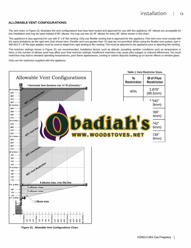
ALLOWABLE VENT CONFIGURATIONS:
The vent chart, in Figure 23, illustrates the vent configurations that have been tested and approved for use with this appliance. 45˚ elbows are acceptable for
this installation and may be used instead of 90˚ elbows. You may use two (2) 45˚ elbows for every 90˚ elbow shown in this chart.
This appliance is also approved for use with 5” x 8” flex venting. Only use flexible venting that is approved for this appliance. Flex vent runs must comply with
the same limitations as the rigid vent chart shown here. Flexible vent runs greater than 10’ total are not permitted. When using the flexible vent system, part #
946-601 5” x 8” flex pipe adaptor must be used to adapt from rigid venting to flex venting. This must be attached to the appliance prior to attaching flex venting.
The restrictor settings shown in Figure 23, are recommended. Installation factors such as altitude, prevailing weather conditions such as temperature or
wind, or the number of elbows used may affect your final restrictor settings. Insufficient restriction may cause pilot outages or reduced efficiencies. Too much
restriction may lead to elevated operating temperatures, poor flame appearances, sooting or carbon deposits building up on burner effects or window glass.
Only use the restrictors supplied with this appliance.
Table 1: Vent Restrictor Sizes.
40’ (12.19m)
35’ (10.67m)
30’ (9.14m)
25’ (7.62m)
* Horizontal Vent Sections rise 1/4”/ft (21mm/m) *
20’ (6.10m)
15’ (4.57m)
9’6” (2.90m)
5’3” (1.60m)
Figure 23. Allowable Vent Configurations Chart.
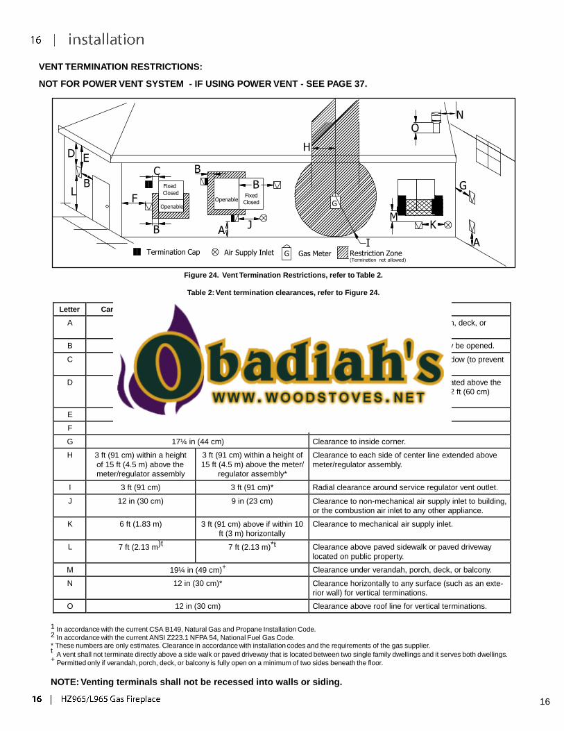
VENT TERMINATION RESTRICTIONS:
NOT FOR POWER VENT SYSTEM - IF USING POWER VENT - SEE PAGE 37.
D E
C B B Fixed
L F
Closed
Openable
B
Openable
A
N O
H
B G Fixed
Closed G
M J K
I A Termination Cap Air Supply Inlet G Gas Meter Restriction Zone
(Termination not allowed)
Figure 24. Vent Termination Restrictions, refer to Table 2.
Table 2: Vent termination clearances, refer to Figure 24.
Letter Canadian Installation 1 US Installation
2 Description
A 12 in (30 cm) Clearance above grade, verandah, porch, deck, or
balcony.
B 12 in (30 cm) 9 in (23 cm) Clearance from window or door that may be opened.
C 12 in (30 cm)* Clearance from permanently closed window (to prevent
condensation).
D 19¼ in (49 cm) Vertical clearance to ventilated soffit located above the
terminal, within a horizontal distance of 2 ft (60 cm)
from center line of terminal.
E 19¼ in (49 cm) Clearance to unventilated soffit.
F 17¼ in (44 cm)* Clearance to outside corner.
G 17¼ in (44 cm) Clearance to inside corner.
H 3 ft (91 cm) within a height
of 15 ft (4.5 m) above the
meter/regulator assembly
3 ft (91 cm) within a height of
15 ft (4.5 m) above the meter/
regulator assembly*
Clearance to each side of center line extended above
meter/regulator assembly.
I 3 ft (91 cm) 3 ft (91 cm)* Radial clearance around service regulator vent outlet.
J 12 in (30 cm) 9 in (23 cm) Clearance to non-mechanical air supply inlet to building,
or the combustion air inlet to any other appliance.
K 6 ft (1.83 m) 3 ft (91 cm) above if within 10
ft (3 m) horizontally
Clearance to mechanical air supply inlet.
L 7 ft (2.13 m)t 7 ft (2.13 m)*t Clearance above paved sidewalk or paved driveway
located on public property.
M 19¼ in (49 cm)+ Clearance under verandah, porch, deck, or balcony.
N 12 in (30 cm)* Clearance horizontally to any surface (such as an exte-
rior wall) for vertical terminations.
O 12 in (30 cm) Clearance above roof line for vertical terminations.
1 In accordance with the current CSA B149, Natural Gas and Propane Installation Code. 2 In accordance with the current ANSI Z223.1 NFPA 54, National Fuel Gas Code.
* These numbers are only estimates. Clearance in accordance with installation codes and the requirements of the gas supplier. t
A vent shall not terminate directly above a side walk or paved driveway that is located between two single family dwellings and it serves both dwellings. +
Permitted only if verandah, porch, deck, or balcony is fully open on a minimum of two sides beneath the floor.
NOTE: Venting terminals shall not be recessed into walls or siding.
16
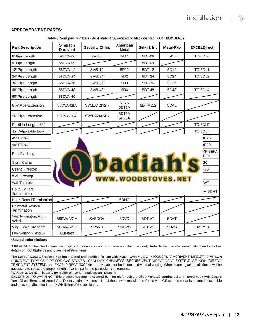
APPROVED VENT PARTS:
Table 3: Vent part numbers (Must state if galvanized or black wanted, PART NUMBERS).
Part Description Simpson
Duravent
Security Chim. American
Metal
Selkirk Int.
Metal-Fab
EXCELDirect
6” Pipe Length 58DVA-06 SV5L6 5D7 5DT-06 5D6 TC-5DL6
9” Pipe Length 58DVA-09 5DT-09
12” Pipe Length 58DVA-12 SV5L12 5D12 5DT-12 5D12 TC-5DL1
24” Pipe Length 58DVA-24 SV5L24 5D2 5DT-24 5D24 TC-5DL2
36” Pipe Length 58DVA-36 SV5L36 5D3 5DT-36 5D36
48” Pipe Length 58DVA-48 SV5L48 5D4 5DT-48 5D48 TC-5DL4
60” Pipe Length 58DVA-60
8 ½” Pipe Extension
58DVA-08A
SV5LA12(12”) 5D7A
5D12A
5DT-AJ12
5DAL
16” Pipe Extension
58DVA-16A
SV5LA24(24”) 5D16A
5D26A
Flexible Length, 36” TC-5DLF
12” Adjustable Length TC-5DLT
45° Elbow 58DVA-E45 SV5E45 5D45L 5DT-EL45 5D45L TE-5DE45
90° Elbow 58DVA-E90 SV5E90 5D90L 5DT-EL90 5D90L TE-5DE90
Roof Flashing
58DVA-F6 SV5F /
SV5FA / SV5FB
5DF12 5DT-AF6
5DT-AF12
5DF XF-6EF / XF-6EFA
/XF-6EFB
Storm Collar 58DVA-SC SV5FC 5DSC 5DT-SC 5DSC TM-SC
Ceiling Firestop 58DVA-FS SV5BF 5DFSP 5DT-FS TM-5CS
Wall Firestop 58DVA-WFS 5DFS
Wall Thimble 58DVA-WT SV5RMS 5DWT 5DT-WT 5DWT TM-5WT
Horiz. Square
Termination
58DVA-HC-*
SV5CHC
5DHCS
5DT-HC
5DHT
TM-5HT/TM-5DHT
Horiz. Round Termination 5DHC
Horizontal Sconce Termination
Vert. Termination, High
Wind
58DVA-VCH
SV5CGV
5DVC
5DT-VT
5DVT
Vinyl Siding Standoff 58DVA-VSS SV5VS 5DHVS 5DT-VS 5DVS TM-VSS
Flex Venting 5” and 8” Duraflex
*Several color choices
IMPORTANT: This chart covers the major components for each of these manufacturers only. Refer to the manufacturers’ catalogue for further
details on roof flashings and other installation items
The L965E/HZ965E fireplace has been tested and certified for use with AMERICAN METAL PRODUCTS “AMERIVENT DIRECT”, SIMPSON
DURAVENT TYPE GS PIPE FOR GAS STOVES. SECURITY CHIMNEY’S “SECURE VENT DIRECT VENT SYSTEM”, SELKIRK “DIRECT-
TEMP VENT SYSTEM”, and EXCELDIRECT “ICC“ kits are available for horizontal and vertical venting. When planning an installation, it will be
necessary to select the proper length of vent pipe for the particular requirements.
WARNING: Do not mix parts from different vent manufacturers’ systems.
EXCEPTION TO WARNING: This product has been evaluated by Intertek for using a Direct Vent GS starting collar in conjunction with Secure
Vent, Direct-Temp, and Ameri Vent Direct venting systems. Use of these systems with the Direct Vent GS starting collar is deemed acceptable
and does not affect the Intertek WH listing of the appliance.
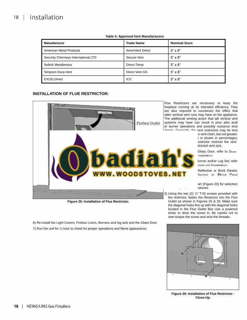
Table 4: Approved Vent Manufacturers
Manufacturer Trade Name Nominal Sizes
American Metal Products AmeriVent Direct 5” x 8”
Security Chimneys International LTD Secure Vent 5” x 8”
Selkirk Metalbestos Direct-Temp 5” x 8”
Simpson Dura-Vent Direct Vent GS 5” x 8”
EXCELDirect ICC 5” x 8”
INSTALLATION OF FLUE RESTRICTOR:
Figure 25: Installation of Flue Restrictor.
6) Re-install the Light Covers, Firebox Liners, Burners and log sets and the Glass Door.
7) Run the unit for ½ hour to check for proper operations and flame appearance.
Flue Restrictors are necessary to keep the
fireplace running at its intended efficiency. They
are also required to counteract the effect that
taller vertical vent runs may have on the appliance.
The additional venting action that tall vertical vent
systems may have can result in poor pilot and/
or burner operations and possibly nuisance shut
downs. Generally, the vent restriction may be less
than what is shown in the vent chart, but not greater.
The vent restrictor size is shown in percentages,
meaning that a 40% restrictor restricts the vent
40% from its fully un-restricted vent size.
1) Remove the Glass Door; refer to Door
removal anD InstallatIon.
2) Remove the Burner and/or Log Set; refer
to Burner removal anD InstallatIon.
3) Remove the Reflective or Brick Panels;
refer to reflectIve or BrIck Panel
InstallatIon.
4) Refer to the Vent Chart (Figure 23) for selection
of the appropriate Restrictor.
5) Using the two (2) ¼” T-20 screws provided with
the restrictor, fasten the Restrictor into the Flue
Outlet as shown in Figures 25 & 26. Make sure
the diagonal holes line up with the diagonal holes
located in the Flue Outlet Box Use a powered
driver to drive the screw in. Be careful not to
over-torque the screw and strip the threads.
Figure 26: Installation of Flue Restrictor -
Close-Up.
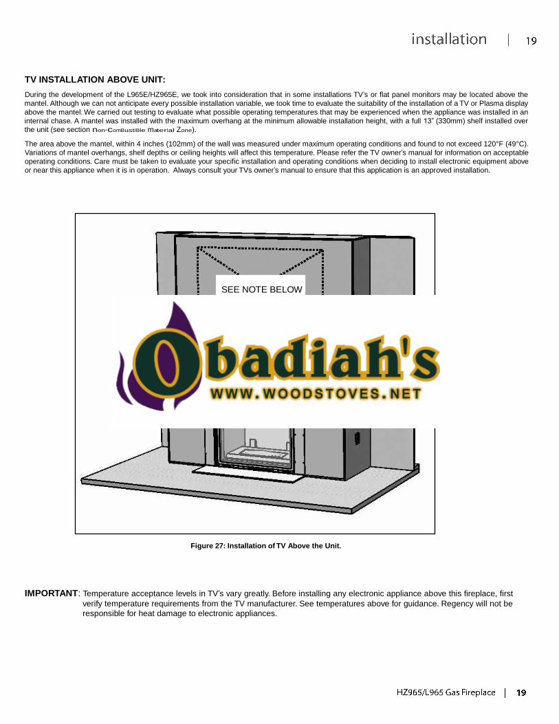
TV INSTALLATION ABOVE UNIT:
During the development of the L965E/HZ965E, we took into consideration that in some installations TV’s or flat panel monitors may be located above the
mantel. Although we can not anticipate every possible installation variable, we took time to evaluate the suitability of the installation of a TV or Plasma display
above the mantel. We carried out testing to evaluate what possible operating temperatures that may be experienced when the appliance was installed in an
internal chase. A mantel was installed with the maximum overhang at the minimum allowable installation height, with a full 13” (330mm) shelf installed over
the unit (see section non-comBustIBle materIal Zone).
The area above the mantel, within 4 inches (102mm) of the wall was measured under maximum operating conditions and found to not exceed 120°F (49°C).
Variations of mantel overhangs, shelf depths or ceiling heights will affect this temperature. Please refer the TV owner’s manual for information on acceptable
operating conditions. Care must be taken to evaluate your specific installation and operating conditions when deciding to install electronic equipment above
or near this appliance when it is in operation. Always consult your TVs owner’s manual to ensure that this application is an approved installation.
SEE NOTE BELOW
Figure 27: Installation of TV Above the Unit.
IMPORTANT: Temperature acceptance levels in TV’s vary greatly. Before installing any electronic appliance above this fireplace, first
verify temperature requirements from the TV manufacturer. See temperatures above for guidance. Regency will not be
responsible for heat damage to electronic appliances.
PLANNING YOUR INSTALLATION:
QUALIFIED INSTALLERS ONLY
Prior to starting your venting installation, refer to the section on Allowable Vent Configurations to make sure your plans fall into the allowable limits of
horizontal and vertical installations.
When planning your installation, it will be necessary to select the proper length of vent pipe for your particular requirements. For horizontal installations,
refer to the section on Clearances to Combustibles to determine the minimum clearance from the rear of the appliance to the wall. It is also important
to note the wall thickness. Select the amount of vertical rise desired for “vertical-to- horizontal” type installations. To determine the length of vent pipe
required for vertical installations, measure the distance from the appliance flue outlet to the ceiling, the ceiling thickness, the vertical rise in an attic or
second story, and allow for sufficient vent height above the roofline. For two-story applications, firestops are required at each floor level. If an offset is
needed in the attic, additional pipe and elbows will be required.
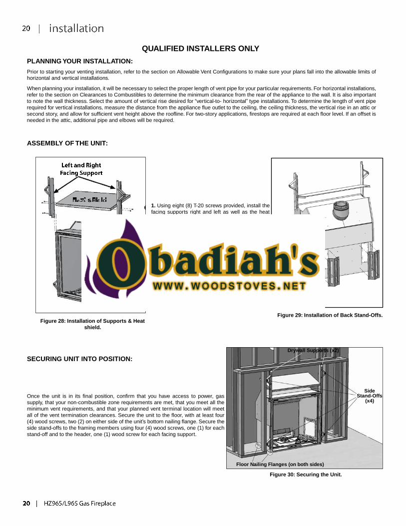
ASSEMBLY OF THE UNIT:
1. Using eight (8) T-20 screws provided, install the
facing supports right and left as well as the heat
shield in the middle, as shown in Figure 28.
2. Using eight (8) T20 screws provided, attach
both back stand-offs, as shown in Figure 29.
Figure 28: Installation of Supports & Heat
shield.
Figure 29: Installation of Back Stand-Offs.
SECURING UNIT INTO POSITION:
Once the unit is in its final position, confirm that you have access to power, gas
supply, that your non-combustible zone requirements are met, that you meet all the
minimum vent requirements, and that your planned vent terminal location will meet
all of the vent termination clearances. Secure the unit to the floor, with at least four
(4) wood screws, two (2) on either side of the unit’s bottom nailing flange. Secure the
side stand-offs to the framing members using four (4) wood screws, one (1) for each
stand-off and to the header, one (1) wood screw for each facing support.
Drywall Supports (x2)
Floor Nailing Flanges (on both sides)
Figure 30: Securing the Unit.
Side
Stand-Offs (x4)
QUALIFIED INSTALLERS ONLY
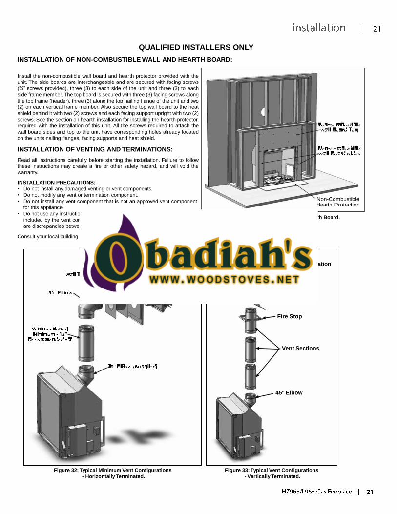
INSTALLATION OF NON-COMBUSTIBLE WALL AND HEARTH BOARD:
Install the non-combustible wall board and hearth protector provided with the
unit. The side boards are interchangeable and are secured with facing screws
(¾” screws provided), three (3) to each side of the unit and three (3) to each
side frame member. The top board is secured with three (3) facing screws along
the top frame (header), three (3) along the top nailing flange of the unit and two
(2) on each vertical frame member. Also secure the top wall board to the heat
shield behind it with two (2) screws and each facing support upright with two (2)
screws. See the section on hearth installation for installing the hearth protector,
required with the installation of this unit. All the screws required to attach the
wall board sides and top to the unit have corresponding holes already located
on the units nailing flanges, facing supports and heat shield.
INSTALLATION OF VENTING AND TERMINATIONS:
Read all instructions carefully before starting the installation. Failure to follow
these instructions may create a fire or other safety hazard, and will void the
warranty.
INSTALLATION PRECAUTIONS:
• Do not install any damaged venting or vent components.
• Do not modify any vent or termination component.
• Do not install any vent component that is not an approved vent component
for this appliance.
• Do not use any instructions other that those included in this manual or those
included by the vent component manufacturer with the venting. When there
are discrepancies between the two, this manual will be considered the final authority.
Consult your local building codes before beginning the installation.
Non-Combustible Hearth Protection
Figure 31: Installation of Wall & Hearth Board.
Vertical Termination
Storm Collar
Roof Flashing
Fire Stop
Vent Sections
45° Elbow
Figure 32: Typical Minimum Vent Configurations
- Horizontally Terminated.
Figure 33: Typical Vent Configurations
- Vertically Terminated.
WARNING
• Always maintain required clearances (air spaces) to nearby combustibles to prevent a fire hazard. Do not fill air spaces with insulation. Unless
stated otherwise, clearances on horizontal vent sections are 2” (51mm) to combustible materials. Clearances to vertical vent sections are 1” (25mm)
to combustible clearances.
• The fireplace and vent system must be vented directly to the outside of the building. Each direct vent fireplace must use its own separate vent
system. Common vent systems are prohibited.
• The flow of combustion and ventilation air not be obstructed.
HORIZONTAL INSTALLATION:
Step 1. Set the fireplace in its desired location. Check to determine if wall studs or roof rafters are in the way when the venting system is attached. If this is
the case, you may want to adjust the location of the appliance.
Step 2. Direct Vent pipe and fittings are designed with special twist-lock connections. Assemble the desired combination of pipe and elbows to the appliance.
See the sections on tyPIcal framIng - Internal chase, external chase or corner InstallatIon for some of the possible vent pathway options. All
installations must fall within the Allowable Vent Configurations shown in Figure 20.
Notes:
(1) Twist-lock procedure: Four (4) indentations, located on the female ends of pipes and fittings, are designed to slide straight onto the male ends of adjacent
pipes and fittings, by orienting the four pipe indentations so they match and slide into the four (4) entry slots on the male ends. Push the pipe sections
completely together, then twist-lock one section clockwise approximately one-quarter turn, until the two (2) sections are fully locked.
(2) Horizontal runs of vent must be supported every 3 feet (915mm). Wall Straps are available for
this purpose.
(3) Sealant is only necessary on the outer tube of the GS Pipe. Run a 1.25 inch (3mm) wide bead of
sealant around the male end of the outer sleeve, as shown in Figure 34, and twist-lock the pipes
or fittings together.
Step 3. With the adaptor and pipe attached to the fireplace, slide the fireplace into its correct
location, and mark the wall for a square hole of the appropriate size. Use 11”x11”
(280x280mm) square hole for 8” x 5” pipe. The center of the square hole should line up
with the centerline of the horizontal pipe, as shown in Figure 35. Cut and frame the square
hole in the exterior wall where the vent will be terminated. If the wall being penetrated is
constructed of non-combustible material, i.e. masonry block or concrete, a hole with zero
clearance to the pipe is acceptable.
Notes:
(1) Any horizontal run of vent must have a ¼ inch (6mm) rise for every 1 foot (305mm) of run towards
the termination. Never allow the vent to run downward. This could cause high temperatures and
may present the possibility of a fire.
(2) The location of the horizontal vent termination on an exterior wall
must meet all local and national building codes, and must not be
easily blocked or obstructed. Termination clearances must comply
with the vent termInatIon restrIctIons section.
Step 4. For a Square Horizontal Vent Termination, place the vent cap
in the center of the square hole and attach to the exterior
wall with the four wood screws provided (refer to Figure 36).
Before attaching the Vent Termination to the exterior wall, run
a bead of non-hardening sealant around its outside edges, so
as to make a seal between it and the wall. If you are using a
Round Horizontal Vent Termination, place an exterior Wall
Firestop over the square hole. Run a bead of non-hardening
sealant around the edges of the Wall Firestop, and attach the
Wall Firestop to the wall with the four wood screws provided.
The arrow on the vent cap should be pointing up. Ensure that
proper clearances to combustible materials are maintained.
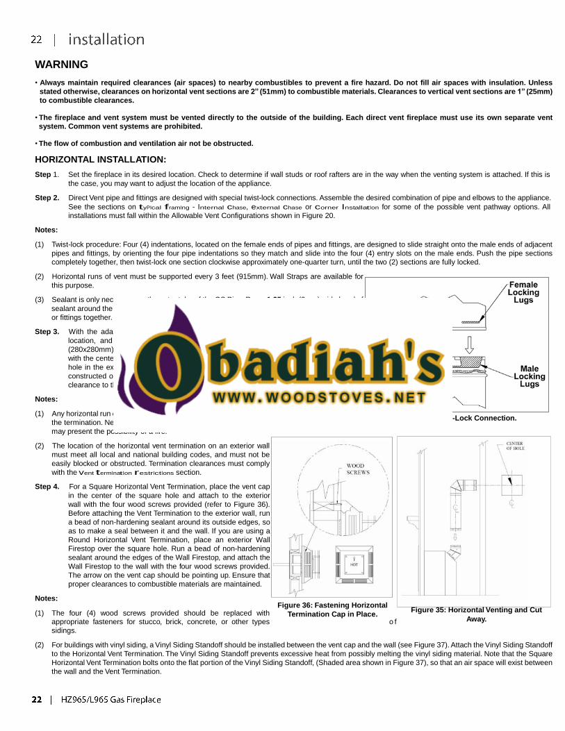
Figure 34: Twist-Lock Connection.
Notes:
(1) The four (4) wood screws provided should be replaced with
Figure 36: Fastening Horizontal
Termination Cap in Place.
Figure 35: Horizontal Venting and Cut
appropriate fasteners for stucco, brick, concrete, or other types o f
sidings.
Away.
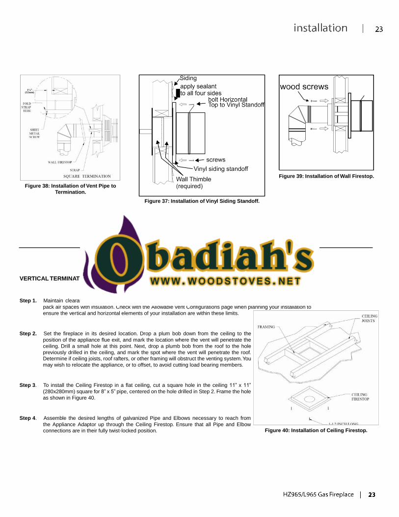
(2) For buildings with vinyl siding, a Vinyl Siding Standoff should be installed between the vent cap and the wall (see Figure 37). Attach the Vinyl Siding Standoff
to the Horizontal Vent Termination. The Vinyl Siding Standoff prevents excessive heat from possibly melting the vinyl siding material. Note that the Square
Horizontal Vent Termination bolts onto the flat portion of the Vinyl Siding Standoff, (Shaded area shown in Figure 37), so that an air space will exist between
the wall and the Vent Termination.
11/4” (32mm)
Figure 38: Installation of Vent Pipe to
Termination.
Figure 37: Installation of Vinyl Siding Standoff.
Figure 39: Installation of Wall Firestop.
VERTICAL TERMINATION INSTALLATION:
Step 1. Maintain clearances between venting and combustible building materials as stated earlier in this section. Do not
pack air spaces with insulation. Check with the Allowable Vent Configurations page when planning your installation to
ensure the vertical and horizontal elements of your installation are within these limits.
Step 2. Set the fireplace in its desired location. Drop a plum bob down from the ceiling to the
position of the appliance flue exit, and mark the location where the vent will penetrate the
ceiling. Drill a small hole at this point. Next, drop a plumb bob from the roof to the hole
previously drilled in the ceiling, and mark the spot where the vent will penetrate the roof.
Determine if ceiling joists, roof rafters, or other framing will obstruct the venting system. You
may wish to relocate the appliance, or to offset, to avoid cutting load bearing members.
Step 3. To install the Ceiling Firestop in a flat ceiling, cut a square hole in the ceiling 11” x 11”
(280x280mm) square for 8” x 5” pipe, centered on the hole drilled in Step 2. Frame the hole
as shown in Figure 40.
Step 4. Assemble the desired lengths of galvanized Pipe and Elbows necessary to reach from
the Appliance Adaptor up through the Ceiling Firestop. Ensure that all Pipe and Elbow
connections are in their fully twist-locked position.
Figure 40: Installation of Ceiling Firestop.
Step 5. Cut a hole in the roof centered on the small drill hole placed
in the roof in Step 2. The hole should be of sufficient size to
meet the minimum requirements for clearance to combustibles,
as specified earlier. Continue to assemble lengths of Pipe and
Elbows necessary to reach from the Ceiling Firestop up through
the roof line.
Notes:
(1) If an offset is necessary in the attic to avoid obstructions, it is important
to support the vent pipe every 3 feet, to avoid excessive stress on the
Elbows, and possible separation. Wall Straps are available for this
purpose (see Figure 41).
(2) Whenever possible, use 45° Elbows, instead of 90° Elbows. The 45°
Elbow offers less restriction to the flow of flue gases and intake air.
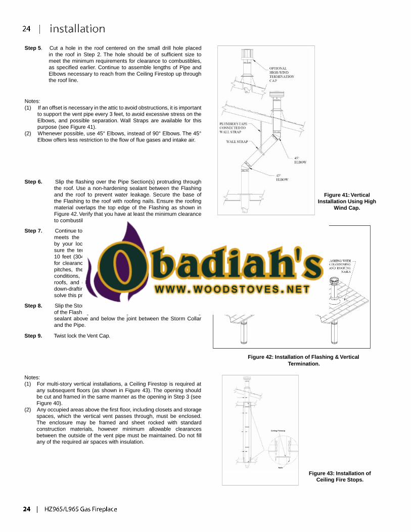
Step 6. Slip the flashing over the Pipe Section(s) protruding through
the roof. Use a non-hardening sealant between the Flashing
and the roof to prevent water leakage. Secure the base of
the Flashing to the roof with roofing nails. Ensure the roofing
material overlaps the top edge of the Flashing as shown in
Figure 42. Verify that you have at least the minimum clearance
to combustibles at the roofline.
Step 7. Continue to add Pipe Sections until the height of the Vent Cap
meets the minimum building code requirements described
by your local codes. In the absence of local codes, make
sure the terminal is 2 feet (610mm) above anything within
10 feet (3046mm) of the vent (refer to Figure 44 & Table 5
for clearances for different pitches). Note that for steep roof
pitches, the vent height must be increased. In high wind
conditions, nearby trees, adjoining rooflines, steep pitched
roofs, and other similar factors can result in poor draft, or
down-drafting. In these cases, increasing the vent height may
solve this problem.
Step 8. Slip the Storm Collar over the Pipe, and push it down to the top
of the Flashing, as shown in Figure 42. Use the non-hardening
sealant above and below the joint between the Storm Collar
and the Pipe.
Step 9. Twist lock the Vent Cap.
Figure 41: Vertical
Installation Using High
Wind Cap.
Figure 42: Installation of Flashing & Vertical
Termination.
Notes:
(1) For multi-story vertical installations, a Ceiling Firestop is required at
any subsequent floors (as shown in Figure 43). The opening should
be cut and framed in the same manner as the opening in Step 3 (see
Figure 40).
(2) Any occupied areas above the first floor, including closets and storage
spaces, which the vertical vent passes through, must be enclosed.
The enclosure may be framed and sheet rocked with standard
construction materials, however minimum allowable clearances
between the outside of the vent pipe must be maintained. Do not fill
any of the required air spaces with insulation.
Ceiling Firestop
Nails
Figure 43: Installation of
Ceiling Fire Stops.
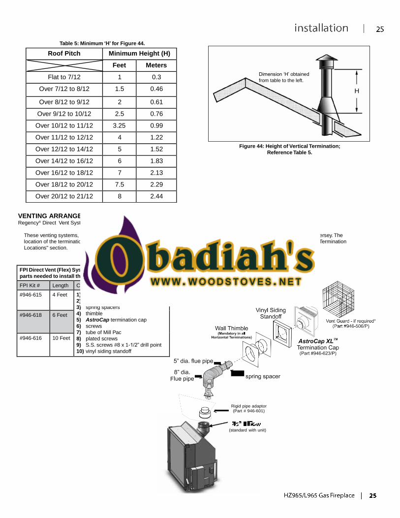
Roof Pitch Minimum Height (H)
Feet Meters
Flat to 7/12 1 0.3
Over 7/12 to 8/12 1.5 0.46
Over 8/12 to 9/12 2 0.61
Over 9/12 to 10/12 2.5 0.76
Over 10/12 to 11/12 3.25 0.99
Over 11/12 to 12/12 4 1.22
Over 12/12 to 14/12 5 1.52
Over 14/12 to 16/12 6 1.83
Over 16/12 to 18/12 7 2.13
Over 18/12 to 20/12 7.5 2.29
Over 20/12 to 21/12 8 2.44
Table 5: Minimum ‘H’ for Figure 44.
Dimension ‘H’ obtained
from table to the left.
H
Figure 44: Height of Vertical Termination;
Reference Table 5.
VENTING ARRANGEMENTS - HORIZONTAL TERMINATION (FLEX): Regency® Direct Vent System
These venting systems, in combination with the HZ965/L965, have been tested and listed as a direct vent system by Warnock Hersey. The
location of the termination cap must conform to the requirements in the Vent Terminal Locations diagram from the "Exterior Vent Termination
Locations" section.
FPI Direct Vent (Flex) System Termination Kits include all the
parts needed to install the HZ965/L965, using a flexible vent.
FPI Kit # Length Contains:
#946-615 4 Feet 1) 8” flexible liner (Kit length)
2) 5” flexible liner (Kit length)
3) spring spacers
4) thimble
5) AstroCap termination cap
6) screws
7) tube of Mill Pac
8) plated screws
9) S.S. screws #8 x 1-1/2” drill point
10) vinyl siding standoff
#946-618 6 Feet
#946-616 10 Feet
Rigid pipe adaptor
(Part # 946-601)
(standard with unit)
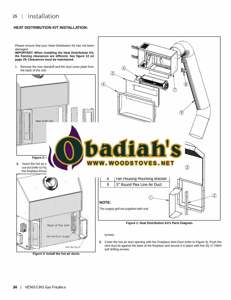
Item Description
1 Hot Air Duct
2 Hot Air Duct Angle
3 Fireplace Vent Duct
4 Fan Bezel
5 Front Access Cover
6 Fan
7 Fan Housing Assembly
8 Fan Housing Mounting Bracket
9 5” Round Flex Line Air Duct
HEAT DISTRIBUTION KIT INSTALLATION:
Please ensure that your Heat Distribution Kit has not been
damaged. IMPORTANT: When installing the Heat Distribution Kit, the framing clearances are different. See figure 12 on page 29. Clearances must be maintained.
1. Remove the rear standoff and the duct cover plate from
the back of the unit.
Rear of the Unit
Duct Cover Plate
Rear Standoff
Figure 2: Remove the duct cover.
2. Insert the hot air duct and the hot air duct angle into the
cut out (refer to Figure 3). Secure the ducts to the back of
the fireplace through the pre-drilled holes with hex head
NOTE:
The supply grill not supplied with unit.
Rear of the Unit
Hot Air Duct Angle
Hot Air Duct
Figure 3: Install the hot air ducts.
Figure 1: Heat Distribution Kit’s Parts Diagram.
screws.
3. Cover the hot air duct opening with the Fireplace Vent Duct (refer to Figure 4). Push the
vent duct kit against the back of the fireplace and secure it in place with five (5) ¼” HWH
self drilling screws.
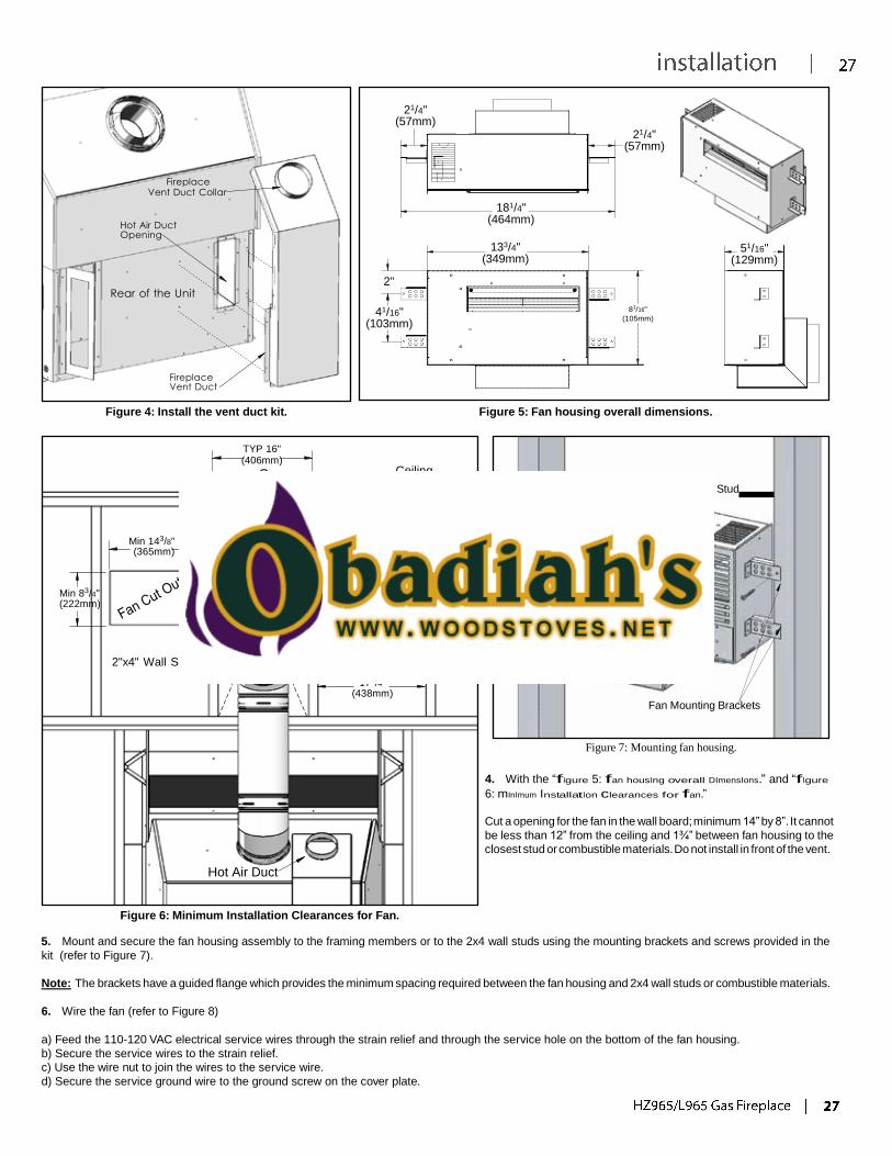
21/4"
(57mm)
21/4" (57mm)
Fireplace
Vent Duct Collar
Hot Air Duct Opening
Rear of the Unit
2"
41/16"
(103mm)
181/4" (464mm)
133/4"
(349mm)
81/16"
(105mm)
51/16" (129mm)
Fireplace Vent Duct
Figure 4: Install the vent duct kit.
Figure 5: Fan housing overall dimensions.
TYP 16" (406mm)
CL Ceiling
2x4 Wall Stud
Min 143/8" (365mm)
12" (305mm)
13/4"
(44mm) 13/4"
(44mm)
Fan Housing
Min 83/4" (222mm)
2"x4" Wall Stud Fan Housing
171/4"
(438mm)
Fan Mounting Brackets
Figure 7: Mounting fan housing.
4. With the “fIgure 5: fan housIng overall DImensIons.” and “fIgure
6: mInImum InstallatIon clearances for fan.”
Hot Air Duct
Cut a opening for the fan in the wall board; minimum 14” by 8”. It cannot
be less than 12” from the ceiling and 1¾” between fan housing to the
closest stud or combustible materials. Do not install in front of the vent.
Figure 6: Minimum Installation Clearances for Fan.
5. Mount and secure the fan housing assembly to the framing members or to the 2x4 wall studs using the mounting brackets and screws provided in the
kit (refer to Figure 7).
Note: The brackets have a guided flange which provides the minimum spacing required between the fan housing and 2x4 wall studs or combustible materials.
6. Wire the fan (refer to Figure 8)
a) Feed the 110-120 VAC electrical service wires through the strain relief and through the service hole on the bottom of the fan housing.
b) Secure the service wires to the strain relief.
c) Use the wire nut to join the wires to the service wire.
d) Secure the service ground wire to the ground screw on the cover plate.
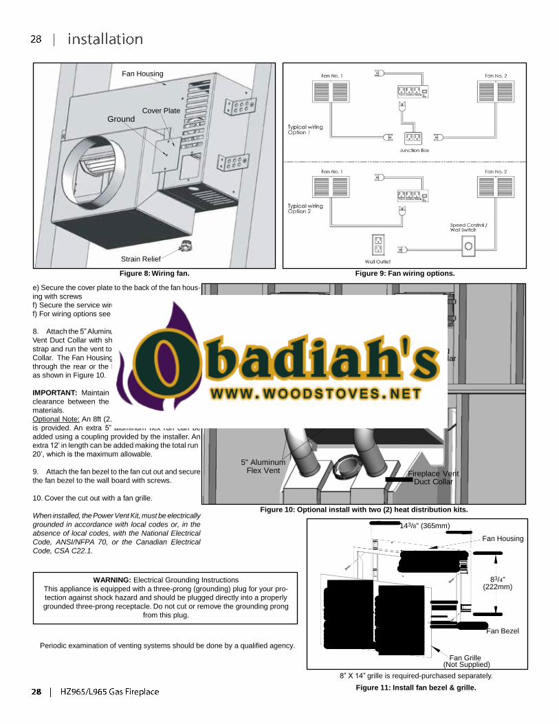
Fan Housing
Ground Cover Plate
Strain Relief
Figure 8: Wiring fan.
e) Secure the cover plate to the back of the fan hous-
ing with screws
f) Secure the service wires to the strain relief
f) For wiring options see Figure 9.
8. Attach the 5” Aluminum Flex Vent to the Fireplace
Vent Duct Collar with sheet metal screws or a vent
strap and run the vent to the Fan Housing Vent Duct
Collar. The Fan Housing Vent Duct can be installed
through the rear or the bottom of the Fan Housing
as shown in Figure 10.
Figure 9: Fan wiring options.
Fan Housing
Vent Duct Collar
IMPORTANT: Maintain a minimum of 2” (51mm)
clearance between the flex lines and combustible
materials.
Optional Note: An 8ft (2.4m) 5” Aluminum Flex Vent
is provided. An extra 5” aluminum flex run can be
added using a coupling provided by the installer. An
extra 12’ in length can be added making the total run
20’, which is the maximum allowable.
9. Attach the fan bezel to the fan cut out and secure
the fan bezel to the wall board with screws.
5" Aluminum
Flex Vent
Fireplace Vent
Duct Collar
10. Cover the cut out with a fan grille.
When installed, the Power Vent Kit, must be electrically
grounded in accordance with local codes or, in the
absence of local codes, with the National Electrical
Code, ANSI/NFPA 70, or the Canadian Electrical
Code, CSA C22.1.
Figure 10: Optional install with two (2) heat distribution kits.
143/8" (365mm)
Fan Housing
WARNING: Electrical Grounding Instructions
This appliance is equipped with a three-prong (grounding) plug for your pro-
tection against shock hazard and should be plugged directly into a properly
grounded three-prong receptacle. Do not cut or remove the grounding prong
from this plug.
83/4" (222mm)
Periodic examination of venting systems should be done by a qualified agency.
Fan Grille
Fan Bezel
(Not Supplied)
8” X 14” grille is required-purchased separately.
Figure 11: Install fan bezel & grille.

60" (1524mm) Chase Minimum Width
26 1/2" (610mm) Chase Minimum
Depth
44 3/4" (1137mm) Minimum
** Minimum Height from the base of the unit.
90" (2286mm) to Internal
Ceiling A
**52 5/16" (1329mm) to Header
Figure 12: Installation Clearances with Heat Distribution Kit.

1 2
H6
POWER VENT KIT INSTALLATION:
Please ensure that your Power Vent Kit has not been
damaged.
1. Plan out the venting and wiring installation. Important
notes to consider when planning where the venting will be
installed:
• Minimum horizontal vent run allowed with no rise
is 1 foot (305mm).
• Horizontal vent runs less than 8 feet (2.44m) require
a 60% restrictor. Refer to the Owner’s Manual on how to
install a restrictor.
• Maximum vent run is 100 feet (30.5m) (H
H + H + H + H ), refer to Figure 2. + V + H +
3 4 5 6
• Maximum below-grade installation is 8 feet (2.4m) (V).
• Multi-elbow installations are possible up to a maximum
of six 90°.
minimum horizontal vent installed.
• Refer to Figure 19 and Table 1 for vent termination
clearances and restrictions.
6-5/8” pipe.
Simpson duravent, Security Chimney, American Metal,
Selkirk Int. Metal Fab., Excel Direct.
Item Description
1 5”x8” to 4”x6⅝” Vent Reducer*
2 4”x6⅝” Wall Thimble
3 Power Vent Assembly
4 Power Vent Control Box
* Item not included
Figure 1: Power Vent Kit’s Parts Diagram.
5"x8" to 4"x65/8" H1
Vent Reducer
4"x65/8"
5"x8" 90o Elbow
90o Elbow
V
Power Vent
H5
H4
H2
H3
Figure 2: Below-grade installation with maximum number of elbows.
4" x 6" Vent
5" x 8" to 4" x 65/8" Vent
Reducer
5" x 8" 90o
Elbow
1ft (305mm)
4” x 6-5/8” vent
97/16" (240mm)
Wall
Thimble Power Vent
141/2"
(368mm)
Power Vent Control Box
2" x 4" Wall Stud
Wall Board
141/2"
(368mm)
141/8"
(359mm)
391/16" (992mm)
44" (1.11m)
Figure 5: Thimble framing dimensions.
Figure 4 Typical overall dimensions with minimum horizontal
vent installed.
• 50 feet (15.25m) of cable is supplied with this kit, if more venting is required, use 706-033 - 100 feet (30.5m) PVK CABLE and connect it as shown on
the wiring diagram in Figure 4.
• Allow for an extra 24”-30” (60-75cm) of cable at the PVK control box for future servicing.
2. Reduce the venting size from 5” x 8” to 4” x 6-5/8 with a vent reducer, see Figure 1.
3. Using the dimensions in Figures 4 & 5, frame an opening for the thimble of 14½” x 14½” (368mm x 368mm).
4. Insert a 2 ft (61cm) length of the power vent electrical cord through the bushing on the bottom left of the inner thimble, shown in Figure 6.
5. Secure the inner thimble to the wall board with screws.
6. Insert the rest of the power vent electrical cord through the bushing on the right bottom of the outer thimble, refer to Figure 7
Wall Board Wall Board
Screw
Vents
Outer Thimble
Inner Thimble Power Vent Electrical Cord
Bushing
Inner Thimble
Power Vent Electrical Cord
Bushing
Screw
Figure 6: Install the inner thimble and the power
vent cords.
Figure 7: Install the outer thimble.
7. Assemble the outer thimble to the inner thimble and secure the outer thimble to the wall board with screws.
8. Remove power vent case cover from power vent assembly by removing 4 x 5/16” screws (2 per side). Pull the top of power vent and then push downward
on power vent case cover to clear exhaust assembly
9. Insert the power vent electrical cord through the Strain Relief on the bottom right of the power vent assembly, refer to Figure 8.
10. Align the power vent assembly with the direct vent pipe that is protruding through the thimble.
11. Secure the power vent assembly in place with screws as seen in Figure 8.
Outer Thimble
Screw
Power Vent Assembly
Vacuum Switch
Strain Relief
Power Vent Electrical Cord
Direct Vent
Pipe
Figure 8: Install the power vent.
Green/Ground Wire
Figure 9: Securing cord with the Strain Relief.
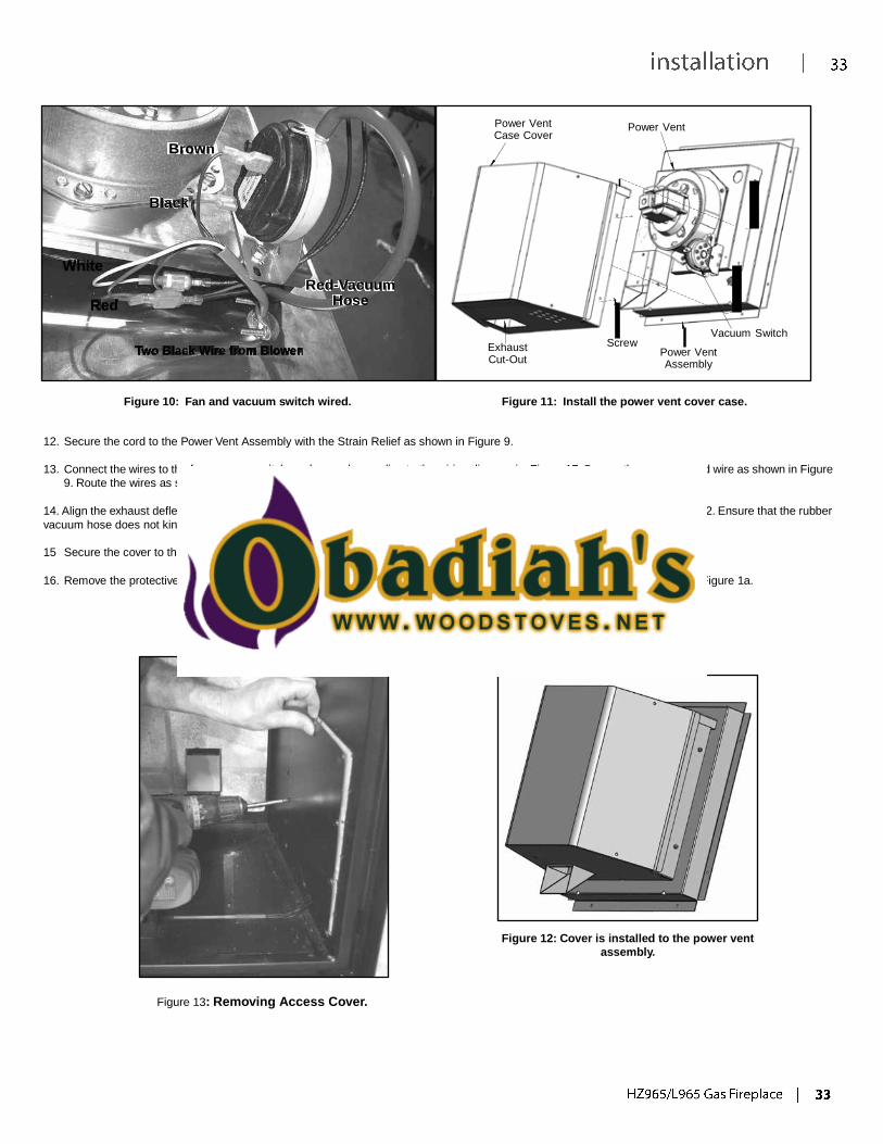
Brown
Power Vent Case Cover
Power Vent
Black
White
Red
Red-Vacuum
Hose
Two Black Wire from Blower
Exhaust Cut-Out
Screw
Vacuum Switch
Power Vent Assembly
Figure 10: Fan and vacuum switch wired. Figure 11: Install the power vent cover case.
12. Secure the cord to the Power Vent Assembly with the Strain Relief as shown in Figure 9.
13. Connect the wires to the fan, vacuum switch, and ground according to the wiring diagram in Figure 17. Secure the green ground wire as shown in Figure
9. Route the wires as shown in Figure 10 to prevent them from getting pinched.
14. Align the exhaust deflector with the exhaust cut out on the bottom of the power vent cover and install, refer to Figure 8, 11 and 12. Ensure that the rubber
vacuum hose does not kink when installed.
15 Secure the cover to the power vent assembly with screws to the left and right sides of the assembly.
16. Remove the protective cover from the PVK Control Box Velcro and secure the power vent control box to the side as shown in Figure 1a.
Figure 12: Cover is installed to the power vent
assembly.
Figure 13: Removing Access Cover.
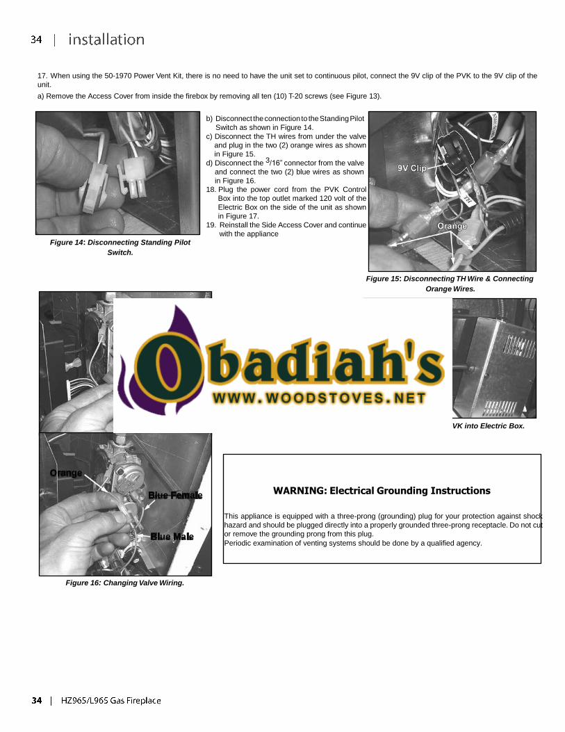
17. When using the 50-1970 Power Vent Kit, there is no need to have the unit set to continuous pilot, connect the 9V clip of the PVK to the 9V clip of the
unit.
a) Remove the Access Cover from inside the firebox by removing all ten (10) T-20 screws (see Figure 13).
Figure 14: Disconnecting Standing Pilot
Switch.
b) Disconnect the connection to the Standing Pilot
Switch as shown in Figure 14.
c) Disconnect the TH wires from under the valve
and plug in the two (2) orange wires as shown
in Figure 15.
d) Disconnect the 3/16” connector from the valve
and connect the two (2) blue wires as shown
in Figure 16.
18. Plug the power cord from the PVK Control
Box into the top outlet marked 120 volt of the
Electric Box on the side of the unit as shown
in Figure 17.
19. Reinstall the Side Access Cover and continue
with the appliance
Figure 15: Disconnecting TH Wire & Connecting
Orange Wires.
Orange
Installation steps as shown in the Instruc-
tion Manual.
When installed, the Power Vent Kit, must
be electrically grounded in accordance
with local codes or, in the absence of local
codes, with the National Electrical Code,
ANSI/NFPA 70, or the Canadian Electrical
Code, CSA C22.1.
Blue
Figure 17: Plugging PVK into Electric Box.
Orange
Blue Female
Blue Male
WARNING: Electrical Grounding Instructions
This appliance is equipped with a three-prong (grounding) plug for your protection against shock
hazard and should be plugged directly into a properly grounded three-prong receptacle. Do not cut
or remove the grounding prong from this plug.
Periodic examination of venting systems should be done by a qualified agency.
Figure 16: Changing Valve Wiring.
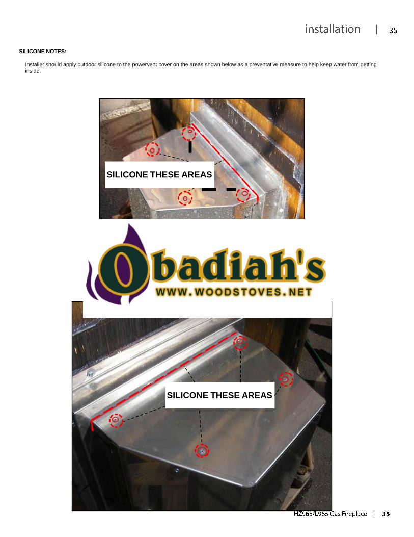
SILICONE NOTES:
Installer should apply outdoor silicone to the powervent cover on the areas shown below as a preventative measure to help keep water from getting
inside.
SILICONE THESE AREAS
SILICONE THESE AREAS
50-1970 WESTGATE
August 25, 2009
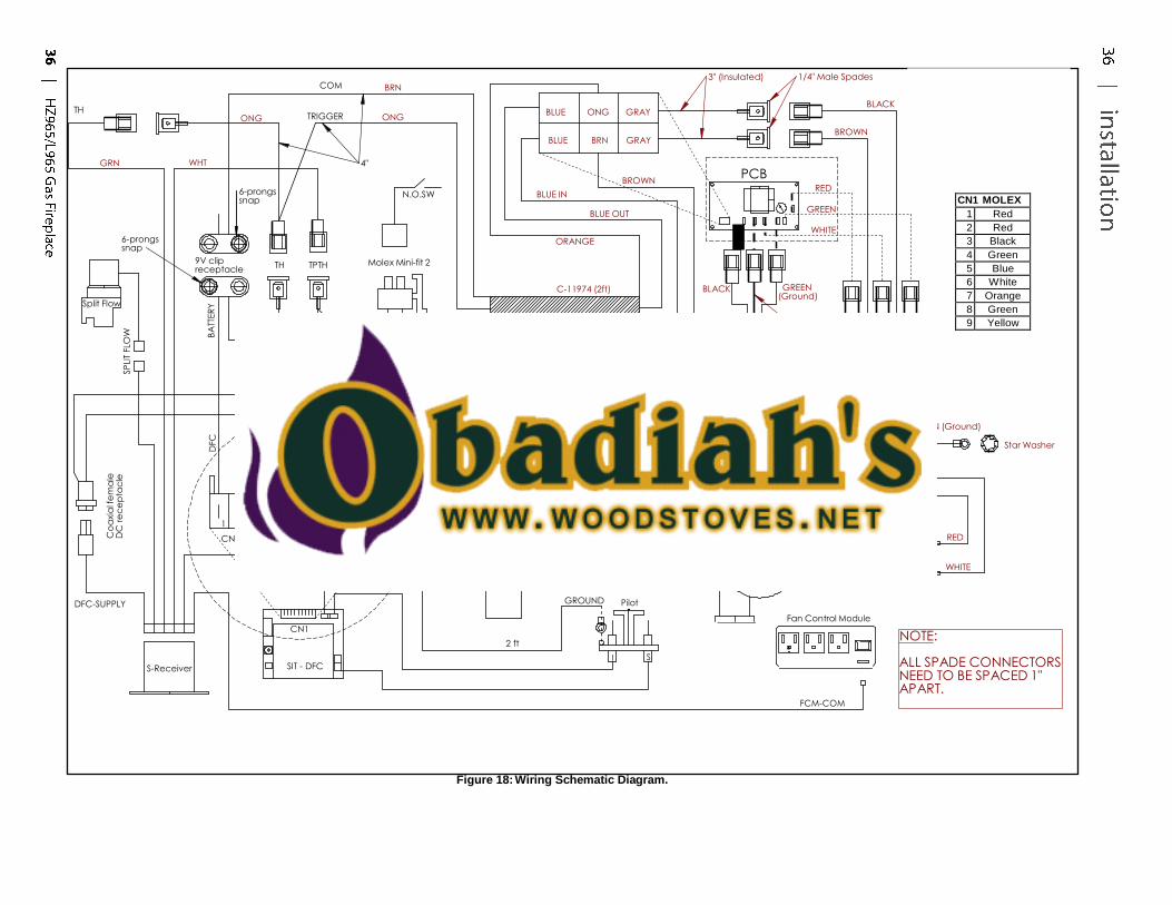
CN1 MOLEX
1 Red
2 Red
3 Black
4 Green
5 Blue
6 White
7 Orange
8 Green
9 Yellow
Co
axia
l fe
ma
le
DC
re
ce
pta
cle
SP
LIT
FLO
W
BA
TTER
Y
DFC
CO
M G
RN
WH
T
TH ONG
COM
TRIGGER
BRN
ONG
BLUE
ONG GRAY
3" (Insulated) 1/4" Male Spades
BLACK
BROWN BLUE BRN GRAY
GRN
WHT
6-prongs snap
4"
N.O.SW
BLUE IN
BROWN
BLUE OUT
PCB
RED
GREEN
WHITE
Split Flow
6-prongs snap
9V clip receptacle
TH TPTH
Molex Mini-fit 2
IPI/CPI
ORANGE
C-11974 (2ft)
BLACK GREEN
(Ground)
WHITE
3/16" Spades (0.187)
BLUE OUT
C-11817 (1ft)
ONG BLUE IN
MOTOR
N.O.SW
(Vacuum)
BROWN
BLACK
C-11896 (50ft)
GREEN (Ground)
Star Washer
1 2 3 4 5 6 7 8 9
M P 3/16" Female Spade (0.187)
CN1 Molex 9 ways female connector SIT 885 Valve
BLOWER
RED
WHITE
DFC-SUPPLY
CN1
2 ft
GROUND Pilot
I S
Fan Control Module
NOTE:
S-Receiver SIT - DFC ALL SPADE CONNECTORS NEED TO BE SPACED 1" APART.
FCM-COM
Figure 18: Wiring Schematic Diagram.
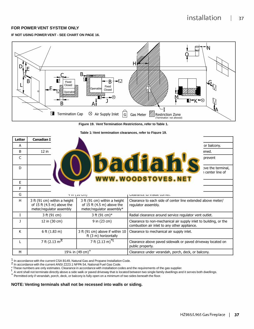
FOR POWER VENT SYSTEM ONLY
IF NOT USING POWER VENT - SEE CHART ON PAGE 16.
D E
C B
B Fixed
L F
Closed
Openable
B
Openable
A
N
O
H
B G Fixed
Closed G
M J K
I A Termination Cap Air Supply Inlet G Gas Meter Restriction Zone
(Termination not allowed)
Figure 19. Vent Termination Restrictions, refer to Table 1.
Table 1: Vent termination clearances, refer to Figure 19.
Letter Canadian Installation 1 US Installation
2 Description
A 24 in (60 cm) Clearance above grade, verandah, porch, deck, or balcony.
B 12 in (30 cm) 9 in (23 cm) Clearance from window or door that may be opened.
C 12 in (30 cm)* Clearance from permanently closed window (to prevent
condensation).
D 4 in (10 cm) Vertical clearance to ventilated soffit located above the terminal, within a horizontal distance of 2 ft (60 cm) from center line of terminal.
E 4 in (10 cm) Clearance to unventilated soffit.
F 12 in (30 cm)* Clearance to outside corner.
G 4 in (10 cm) Clearance to inside corner.
H 3 ft (91 cm) within a height of 15 ft (4.5 m) above the meter/regulator assembly
3 ft (91 cm) within a height of 15 ft (4.5 m) above the meter/regulator assembly*
Clearance to each side of center line extended above meter/
regulator assembly.
I 3 ft (91 cm) 3 ft (91 cm)* Radial clearance around service regulator vent outlet.
J 12 in (30 cm) 9 in (23 cm) Clearance to non-mechanical air supply inlet to building, or the combustion air inlet to any other appliance.
K 6 ft (1.83 m) 3 ft (91 cm) above if within 10 ft (3 m) horizontally
Clearance to mechanical air supply inlet.
L 7 ft (2.13 m)t 7 ft (2.13 m)*t Clearance above paved sidewalk or paved driveway located on
public property.
M 19¼ in (49 cm)+ Clearance under verandah, porch, deck, or balcony.
1 In accordance with the current CSA B149, Natural Gas and Propane Installation Code. 2 In accordance with the current ANSI Z223.1 NFPA 54, National Fuel Gas Code.
* These numbers are only estimates. Clearance in accordance with installation codes and the requirements of the gas supplier. t
A vent shall not terminate directly above a side walk or paved driveway that is located between two single family dwellings and it serves both dwellings. +
Permitted only if verandah, porch, deck, or balcony is fully open on a minimum of two sides beneath the floor.
NOTE: Venting terminals shall not be recessed into walls or siding.
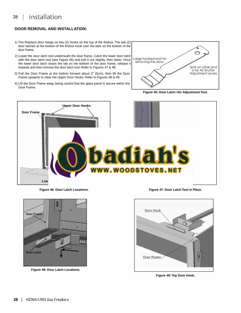
DOOR REMOVAL AND INSTALLATION:
1) The fireplace door hangs on two (2) hooks on the top of the firebox. The two (2)
door latches at the bottom of the firebox hook over the tabs on the bottom of the
door frame.
2) Lower the door latch tool underneath the door frame. Catch the lower door latch
with the door latch tool (see Figure 45) and pull it out slightly, then down. Once
the lower door latch clears the tab on the bottom of the door frame, release it
inwards and then remove the door latch tool. Refer to Figures 47 & 48.
3) Pull the Door Frame at the bottom forward about 2” (5cm), then lift the Door
Frame upwards to clear the Upper Door Hooks. Refer to Figures 48 & 49.
4) Lift the Door Frame away, being careful that the glass panel is secure within the
Door Frame.
Large hooked end for
removing the door.
Slots on other end
is for Air Shutter Adjustment Levers
Figure 45: Door Latch /Air Adjustment Tool.
Door Frame
Upper Door Hooks
Lower Door Latches
Figure 46: Door Latch Locations. Figure 47: Door Latch Tool in Place.
Figure 48: Door Latch Locations.
Figure 49: Top Door Hook.
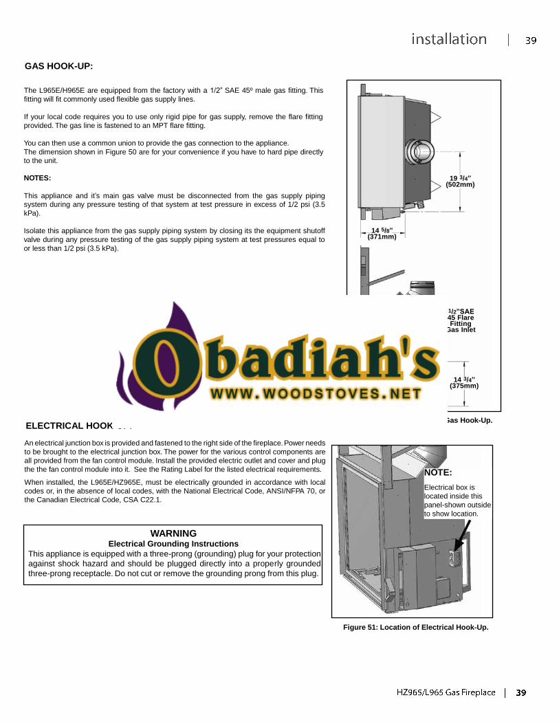
GAS HOOK-UP:
The L965E/H965E are equipped from the factory with a 1/2” SAE 45º male gas fitting. This
fitting will fit commonly used flexible gas supply lines.
If your local code requires you to use only rigid pipe for gas supply, remove the flare fitting
provided. The gas line is fastened to an MPT flare fitting.
You can then use a common union to provide the gas connection to the appliance.
The dimension shown in Figure 50 are for your convenience if you have to hard pipe directly
to the unit.
NOTES:
This appliance and it’s main gas valve must be disconnected from the gas supply piping
system during any pressure testing of that system at test pressure in excess of 1/2 psi (3.5
kPa).
Isolate this appliance from the gas supply piping system by closing its the equipment shutoff
valve during any pressure testing of the gas supply piping system at test pressures equal to
or less than 1/2 psi (3.5 kPa).
14 5/8” (371mm)
19 3/4” (502mm)
1/2”SAE 45 Flare Fitting
Gas Inlet
14 3/4” (375mm)
ELECTRICAL HOOK-UP: Figure 50: Location of Gas Hook-Up.
An electrical junction box is provided and fastened to the right side of the fireplace. Power needs
to be brought to the electrical junction box. The power for the various control components are
all provided from the fan control module. Install the provided electric outlet and cover and plug
the the fan control module into it. See the Rating Label for the listed electrical requirements.
When installed, the L965E/HZ965E, must be electrically grounded in accordance with local
codes or, in the absence of local codes, with the National Electrical Code, ANSI/NFPA 70, or
the Canadian Electrical Code, CSA C22.1.
NOTE:
Electrical box is
located inside this
panel-shown outside
to show location.
WARNING Electrical Grounding Instructions
This appliance is equipped with a three-prong (grounding) plug for your protection
against shock hazard and should be plugged directly into a properly grounded
three-prong receptacle. Do not cut or remove the grounding prong from this plug.
Figure 51: Location of Electrical Hook-Up.
LP GAS CONVERSION:
WARNING: This conversion kit shall be installed by a qualified service agency in accordance with
the manufacturer’s instructions and all applicable codes and requirements of the authority having
jurisdiction. If the information in these instructions is not followed exactly, a fire, explosion or
production of carbon monoxide may result causing property damage, personal injury or loss of life.
The qualified service agency is responsible for the proper installation of this kit. The installation is
not proper and complete until the operation of the converted appliance is checked as specified in
the manufacturer’s instructions supplied with the kit.
1. Ensure all the components of the conversion kit are accounted
for. There should be a pilot orifice, left & right for the glass
tray orifices, left & right for the log burner orifices, regulator
diaphragm, servo regulator, and conversion label.
2. If the unit has already been connected to a gas supply, shut off
the gas supply to the unit.
3. If the unit has been run, shut off and allow cooling to room
temperature.
4. Remove the fireplace door. (see Door removal anD InstallatIon).
5. Remove the burner, glass crystals and firebox liners. (see each
applicable section in this manual),
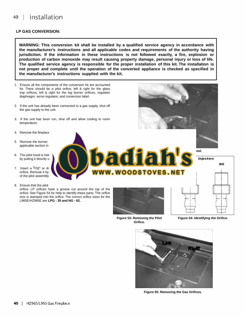
6. The pilot hood is held in with spring pressure. Remove the hood
by pulling it directly up from the pilot assembly (Figure 52).
7. Insert a 5/32” or 4mm Allen wrench into the top of the pilot
orifice. Remove it by rotating it counter-clock wise until it is free
of the pilot assembly (Figure 53).
8. Ensure that the pilot orifice you are about to install is the correct
orifice. LP orifices have a groove cut around the top of the
orifice. See Figure 54 for help to identify these parts. The orifice
size is stamped into the orifice. The correct orifice sizes for the
L965E/HZ965E are LPG - 35 and NG - 62.
Figure 52: Removing the hood.
Figure 53: Removing the Pilot
Orifice.
Figure 54: Identifying the Orifice.
Left
Right
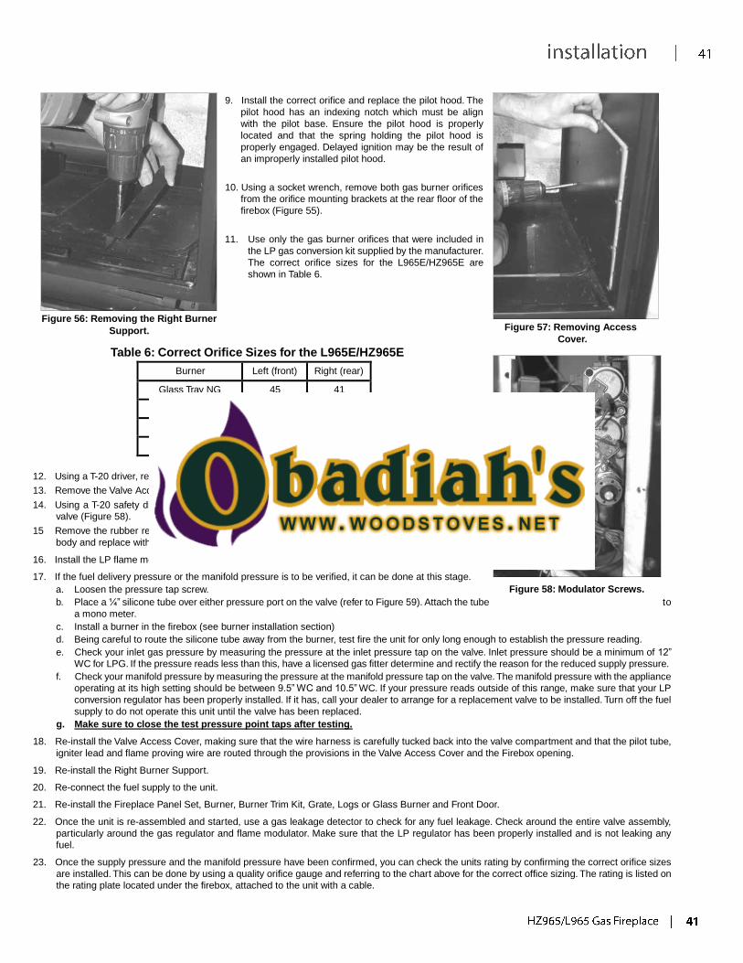
Figure 55: Removing the Gas Orifices.
9. Install the correct orifice and replace the pilot hood. The
pilot hood has an indexing notch which must be align
with the pilot base. Ensure the pilot hood is properly
located and that the spring holding the pilot hood is
properly engaged. Delayed ignition may be the result of
an improperly installed pilot hood.
10. Using a socket wrench, remove both gas burner orifices
from the orifice mounting brackets at the rear floor of the
firebox (Figure 55).
11. Use only the gas burner orifices that were included in
the LP gas conversion kit supplied by the manufacturer.
The correct orifice sizes for the L965E/HZ965E are
shown in Table 6.
Figure 56: Removing the Right Burner
Support. Figure 57: Removing Access Cover.
Table 6: Correct Orifice Sizes for the L965E/HZ965E
Burner Left (front) Right (rear)
Glass Tray NG 45 41
Glass Tray LP 55 53
Log Burner NG 45 41
Log Burner LP 55 53
12. Using a T-20 driver, remove the Right Burner Support (Figure 56).
13. Remove the Valve Access Cover by removing all ten (10) T-20 screws (Figure 57).
14. Using a T-20 safety driver, remove the two (2) screws that hold the flame modulator from the gas
valve (Figure 58).
15 Remove the rubber regulator diaphragm that is situated between the servo regulator and the valve
body and replace with the one provide in the LP conversion kit.
16. Install the LP flame modulator, with the new longer T-20 screws, included in the LP conversion kit.
17. If the fuel delivery pressure or the manifold pressure is to be verified, it can be done at this stage.
a. Loosen the pressure tap screw.
Figure 58: Modulator Screws.
b. Place a ¼” silicone tube over either pressure port on the valve (refer to Figure 59). Attach the tube to
a mono meter.
c. Install a burner in the firebox (see burner installation section)
d. Being careful to route the silicone tube away from the burner, test fire the unit for only long enough to establish the pressure reading.
e. Check your inlet gas pressure by measuring the pressure at the inlet pressure tap on the valve. Inlet pressure should be a minimum of 12”
WC for LPG. If the pressure reads less than this, have a licensed gas fitter determine and rectify the reason for the reduced supply pressure.
f. Check your manifold pressure by measuring the pressure at the manifold pressure tap on the valve. The manifold pressure with the appliance
operating at its high setting should be between 9.5” WC and 10.5” WC. If your pressure reads outside of this range, make sure that your LP
conversion regulator has been properly installed. If it has, call your dealer to arrange for a replacement valve to be installed. Turn off the fuel
supply to do not operate this unit until the valve has been replaced.
g. Make sure to close the test pressure point taps after testing.
18. Re-install the Valve Access Cover, making sure that the wire harness is carefully tucked back into the valve compartment and that the pilot tube,
igniter lead and flame proving wire are routed through the provisions in the Valve Access Cover and the Firebox opening.
19. Re-install the Right Burner Support.
20. Re-connect the fuel supply to the unit.
21. Re-install the Fireplace Panel Set, Burner, Burner Trim Kit, Grate, Logs or Glass Burner and Front Door.
22. Once the unit is re-assembled and started, use a gas leakage detector to check for any fuel leakage. Check around the entire valve assembly,
particularly around the gas regulator and flame modulator. Make sure that the LP regulator has been properly installed and is not leaking any
fuel.
23. Once the supply pressure and the manifold pressure have been confirmed, you can check the units rating by confirming the correct orifice sizes
are installed. This can be done by using a quality orifice gauge and referring to the chart above for the correct office sizing. The rating is listed on
the rating plate located under the firebox, attached to the unit with a cable.
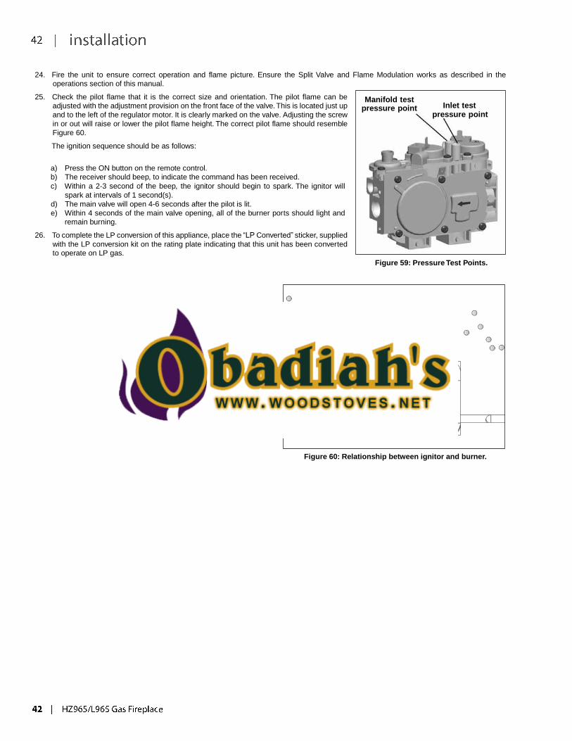
24. Fire the unit to ensure correct operation and flame picture. Ensure the Split Valve and Flame Modulation works as described in the
operations section of this manual.
25. Check the pilot flame that it is the correct size and orientation. The pilot flame can be
adjusted with the adjustment provision on the front face of the valve. This is located just up
and to the left of the regulator motor. It is clearly marked on the valve. Adjusting the screw
in or out will raise or lower the pilot flame height. The correct pilot flame should resemble
Figure 60.
The ignition sequence should be as follows:
a) Press the ON button on the remote control.
b) The receiver should beep, to indicate the command has been received.
c) Within a 2-3 second of the beep, the ignitor should begin to spark. The ignitor will
spark at intervals of 1 second(s).
d) The main valve will open 4-6 seconds after the pilot is lit.
e) Within 4 seconds of the main valve opening, all of the burner ports should light and
remain burning.
26. To complete the LP conversion of this appliance, place the “LP Converted” sticker, supplied
with the LP conversion kit on the rating plate indicating that this unit has been converted
to operate on LP gas.
Manifold test
pressure point Inlet test pressure point
Figure 59: Pressure Test Points.
Burner
5/16” (8mm)
Pilot
Figure 60: Relationship between ignitor and burner.
GLASS BURNER REMOVAL/INSTALLATION:
1) Removal the front panel of the burner by removing 2 screws in the locations
shown in Figure 61 and Figure 62.
Figure 61: Front Panel Screw Locations
Figure 62: Removing Front Panel
Screws
2) After the screws are removed, lift out the front panel as shown in Figure 63.
Figure 63: Lift Out Front Panel
4) Carefully pull the burner forward (see Figure 65) away from the
mixing tubes. When clear of the mixing tubes, lift the burner
up and out.
Figure 65: Move Burner away from Mixing Tubes
5) To install, reverse steps.
3) Remove the 4 screws on the burner in locations shown in Figure 64.
Figure 64: Burner Screw Locations
GLASS CRYSTAL / STONES INSTALLATION :
Evenly spread the Glass Crystals or optional Ceramic Spa Stones over the burner. Ensure the crystals (or stones) do not overlap too much as this
will effect the flame pattern.
IMPORTANT NOTE:
Only the supplied approved Glass Crystals and Ceramic Spa Stones are to be used with these fireplaces. Use of any other type of glass crystals
or stones can alter the unit's performance, any damage caused by the use of any unapproved glass or stones will not be covered under warranty.
When using Ceramic Spa Stones DO NOT cover burner ports or pilot light that lead to pilot flame. Ensure the crystals or stones do not overlap
excessively as this will effect the flame pattern.
BURNER PACKAGES
Unit *Glass Crystals **Ceramic Spa Stones
HZ965 12 lbs 140 spa stones
NOTE: * Glass Crystals are available in 1lb and 5lb bags.
**Each Ceramic Spa stone package contains 70 stones.
Figure 66 Figure 67
1) Start Crystals on back Burner and
Firebox Floor
Figure 68
2) Work Crystals downwards to front
of Burner and Firebox Floor
Figure 69 Figure 70 Figure 71
3) Work Crystals downwards to front
edge of Firebox Floor
4) Crystals shown spread evenly over the burner and firebox base.
5) Ensure Crystals do not block the
front of the pilot hood and flame to
light the burner.
NOTE: Correct final glass installation of Crystals as shown in step 4 and 5.
The Burner and Firebox Floor should not be visible when the flame is out.
OPTIONAL SPA STONES INSTALLATION (AROUND BURNER)
Figure 72 Figure 73
NOTE: Spa Stones are NOT to be placed anywhere on the Pilot assembly area.
Glass Crystals to be installed on the burner and firebox floor prior to installing stones.
nel
*
REFLECTIVE PANEL INSTALLATION / REMOVAL:
Before installation, panels must be handled and cleaned as per instructions noted below:
Black Enamel Panels
• Black Enamel panels must be inspected for scratches and dimples prior to installation. All claims to be recorded at this time. Claims for damage after installation will not receive consideration.
• Black Enamel panels will discolor a little during normal operation. This is normal and should not be considered a defect.
All hand and finger marks MUST be cleaned off with a soft cloth.
Use an ammonia based cleaner (ie. glass cleaner) to remove any fingerprints before applying heat to the unit. Failure to do this will result in burn stain on panels which you will be unable to remove. Not protected by product warranty.
1. Install the Rear Porcelain Panel by placing it behind the burner. Use cau-
tion- do not scratch the panel.
Figure 76: Panel /Unit Alignment.
3. Install the Top Panel by placing it on top of the Rear Panel and behind the
Left Panel (see Figure 77). Hold with one hand then place right side panel.
Figure 74: Rear Porcelain Panel
2. Install the Left Reflective Panel; it should be flush with the outer edge of
the firebox (see Figure 76).
With panel in position, slide panel clip in until it touches the panel, tighten
panel clip screws as shown in Figure 75.
Figure 77: Upper Rear Porcelain Panel
Figure 75: Side Porcelain Panel and Pa
Clip
4. Repeat same procedure in Step 2 to install Right Side Panel.
5. To remove panels, reverse steps.
Figure 78: Final Install
BRICK PANEL INSTALLATION / REMOVAL:
BRICk PaneL InStaLLatIon / RemovaL:
1) Loosen screws securing Brick Panel Clip shown in Figure 76 and slide
Clip away from wall of unit.
Figure 76: Brick Clip
4) Slide the upper back panel in behind the left side panel and on top
of the lower back panel as shown in Figure 79.
Figure 79: Upper Back Brick Panel
2) Slide the lower back panel in first and rest it on the rear wall
support bracket as shown in Figure 77.
Figure 77: Lower Back Brick Panel
3) Slide Left Brick Panel in between wall of unit and Brick Clip as shown
in and Figure 78. Front edge of panel must be flush with firebox edge,
side panel will now hold rear panel up against back wall.
Slide Panel Clip until it is snug against the Left Side Brick Panel and
retighten screw to secure clip.
5) Follow directions from Step 3 to install Right Side Panel to complete
installation.
Figure 80: Right Side Brick Panel
Figure 81: Completed Install
Figure 78: Left Brick Panel
Install
6) To remove Brick Panels, reverse steps.

919-129a 1 04/03/12

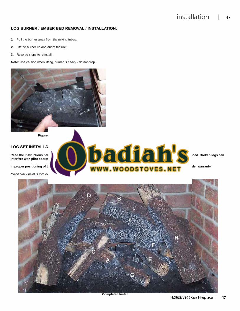
LOG BURNER / EMBER BED REMOVAL / INSTALLATION:
1. Pull the burner away from the mixing tubes.
2. Lift the burner up and out of the unit.
3. Reverse steps to reinstall.
Note: Use caution when lifting, burner is heavy - do not drop.
Figure 79: Burner Removal
LOG SET INSTALLATION:
Read the instructions below carefully and refer to the images. If the logs are broken do not use the unit until they are replaced. Broken logs can
interfere with pilot operation.
Improper positioning of the logs may create carbon build-up and can alter the unit's performance which is not covered under warranty.
*Satin black paint is included if touch ups are required.
D B
F
H
F
C
A E
G
Completed Install
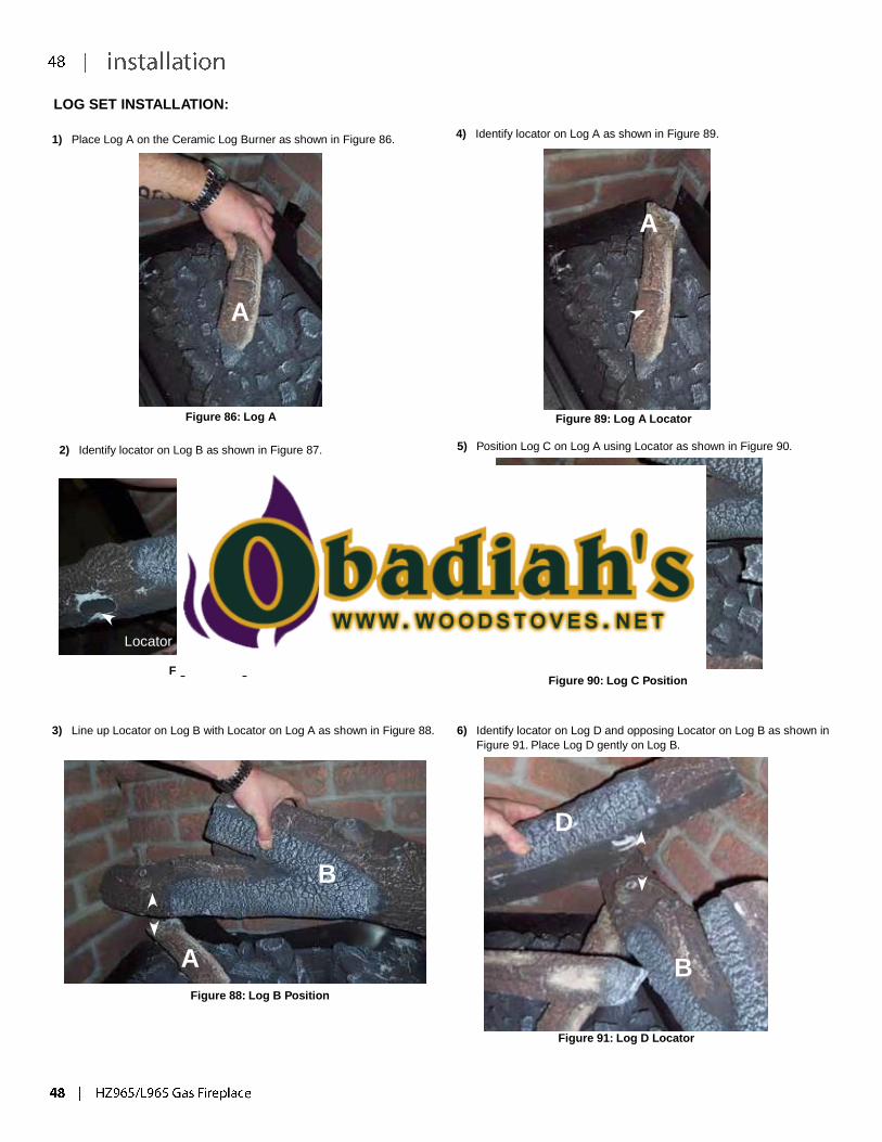
LOG SET INSTALLATION:
1) Place Log A on the Ceramic Log Burner as shown in Figure 86. 4) Identify locator on Log A as shown in Figure 89.
A
A
Figure 86: Log A Figure 89: Log A Locator
2) Identify locator on Log B as shown in Figure 87. 5) Position Log C on Log A using Locator as shown in Figure 90.
B
C
A Locator
Figure 87: Log B Locator Figure 90: Log C Position
3) Line up Locator on Log B with Locator on Log A as shown in Figure 88. 6) Identify locator on Log D and opposing Locator on Log B as shown in
Figure 91. Place Log D gently on Log B.
D
B
A B
Figure 88: Log B Position
Figure 91: Log D Locator
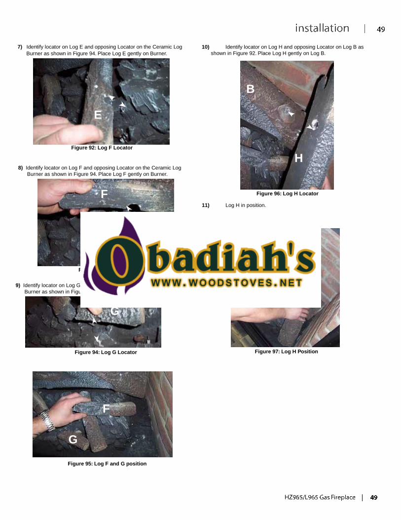
H
7) Identify locator on Log E and opposing Locator on the Ceramic Log
Burner as shown in Figure 94. Place Log E gently on Burner.
10) Identify locator on Log H and opposing Locator on Log B as
shown in Figure 92. Place Log H gently on Log B.
B
E
Figure 92: Log F Locator
8) Identify locator on Log F and opposing Locator on the Ceramic Log
Burner as shown in Figure 94. Place Log F gently on Burner.
F
H
Figure 96: Log H Locator 11) Log H in position.
Figure 93: Log F Locator
9) Identify locator on Log G and opposing Locator on the Ceramic Log
Burner as shown in Figure 94. Place Log G gently on Burner.
G
Figure 94: Log G Locator Figure 97: Log H Position
F
G
Figure 95: Log F and G position
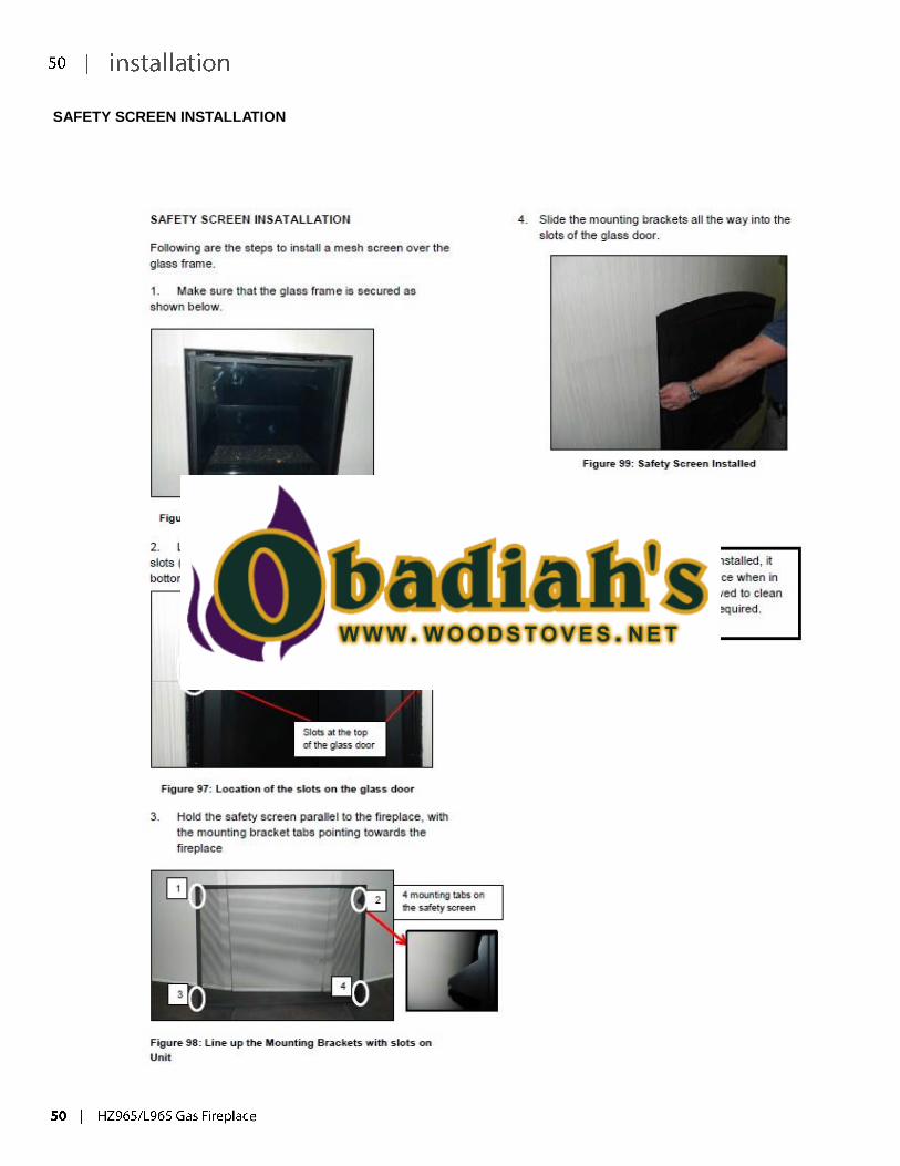
SAFETY SCREEN INSTALLATION
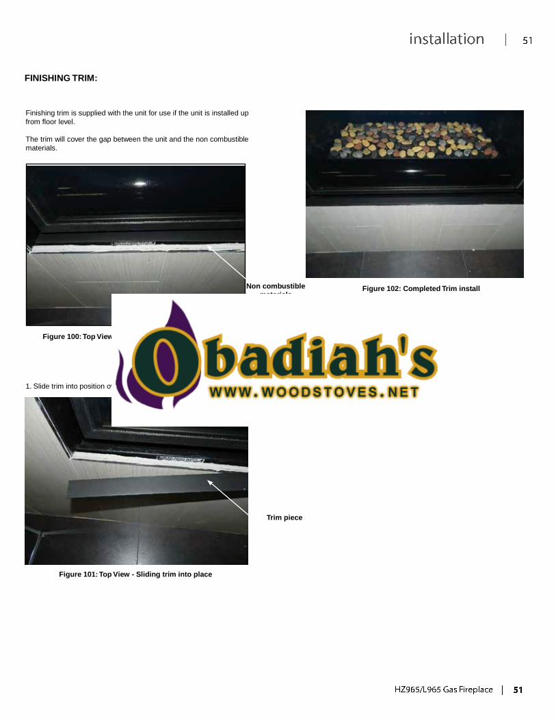
FINISHING TRIM:
Finishing trim is supplied with the unit for use if the unit is installed up
from floor level.
The trim will cover the gap between the unit and the non combustible
materials.
Non combustible
materials
Figure 102: Completed Trim install
Figure 100: Top View - exposed non combustible materials
1. Slide trim into position over exposed non combustible materials.
Trim piece
Figure 101: Top View - Sliding trim into place
START-UP & OPERATION
NORMAL SOUNDS DURING OPERATION:
Table 1: Normal Sounds
Component Sound & Reason
Fascia Creaking when heating up or cooling down.
Burner Light pop or poof when turned off; this is more common with LP units.
Pilot Flame Quiet whisper while the pilot flame in on.
Gas Control Valve Dull click when turning on or off, this is the valve opening and closing.
REMOTE CONTROL OPERATIONS:
The Proflame GTMFS is a modular remote control system that directs the functions of the L965E / HZ965E. The Proflame GTMFS is configured to control the
on/off main burner operation, its flame levels and provides on/off and Smart thermostatic control of the appliance. The system controls a remotely actuated
120V/60Hz power outlet, fan speed through six (6) levels and has a constantly powered 120V/60Hz power outlet.
WARNING
THE TRANSMITTER AND RECEIVER ARE RADIO FREQUENCE DEVICES. PLACING THE RECEIVER IN OR NEAR METAL MAY SEVERELY REDUCE
THE SIGNAL RANGE.
ATTENTION!
- TURN “OFF” THE MAIN GAS SUPPLY OF THE APPLIANCE DURING INSTALLATION OR MAINTENANCE OF THE RECEIVER.
- PLACE THE RECEIVER’S 3 POSITION SLIDER SWITCH IN THE “OFF” POSITION DURING INSTALLATION OR MAINTENANCE.
- TURN “OFF” MAIN GAS SUPPLY TO THE APPLIANCE PRIOR TO REMOVING OR REINSERTING THE BATTERIES IN THE RECEIVER.
- DURING APPLIANCE INSTALLATION/MAINTENANCE OR IN CASE OF REMOTE CONTROL MALFUNCTION TURN OFF THE FAN CONTROL
MODULE USING THE “ON/OFF” MAIN POWER SWITCH ON THE FRONT PANEL OF THE FCM.
TECHNICAL DATA
Transmitter (Remote Control):
Supply voltage 4.5 V (three 1.5 V AAA batteries)
Ambient temperature ratings 0 - 50 °C (32 - 122 °F)
Receiver:
Supply voltage 6.0 V (four 1.5 V AA batteries)
Fan Control Module:
Supply voltage/frequency: 120 V / 60 Hz
Aux switched output: 120 V / 60 Hz / 2 A
Fan speed output: 120 V / 60 Hz / 1 A
SYSTEM DESCRIPTION:
The Proflame Remote Control System consists of three (3) elements:
1. Proflame Transmitter.
2. Proflame Receiver and a wiring harness to connect the Receiver to the gas valve, stepper motor and Fan Control Module.
3. Proflame Fan Control Module (FCM)
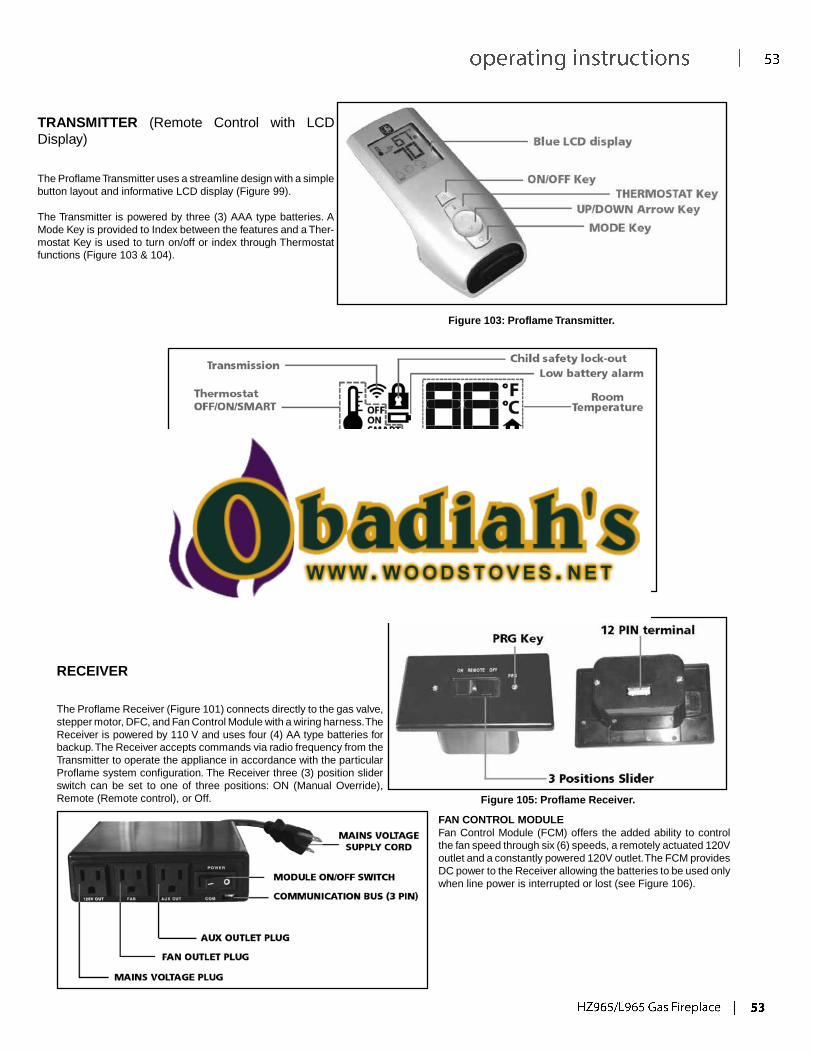
TRANSMITTER (Remote Control with LCD
Display)
The Proflame Transmitter uses a streamline design with a simple
button layout and informative LCD display (Figure 99).
The Transmitter is powered by three (3) AAA type batteries. A
Mode Key is provided to Index between the features and a Ther-
mostat Key is used to turn on/off or index through Thermostat
functions (Figure 103 & 104).
Figure 103: Proflame Transmitter.
Split Flow
Figure 104: Proflame Transmitter LCD Screen.
RECEIVER
The Proflame Receiver (Figure 101) connects directly to the gas valve,
stepper motor, DFC, and Fan Control Module with a wiring harness.The
Receiver is powered by 110 V and uses four (4) AA type batteries for
backup. The Receiver accepts commands via radio frequency from the
Transmitter to operate the appliance in accordance with the particular
Proflame system configuration. The Receiver three (3) position slider
switch can be set to one of three positions: ON (Manual Override),
Remote (Remote control), or Off.
Figure 105: Proflame Receiver.
FAN CONTROL MODULE
Fan Control Module (FCM) offers the added ability to control
the fan speed through six (6) speeds, a remotely actuated 120V
outlet and a constantly powered 120V outlet.The FCM provides
DC power to the Receiver allowing the batteries to be used only
when line power is interrupted or lost (see Figure 106).

Figure 106: Proflame Fan Control Module.
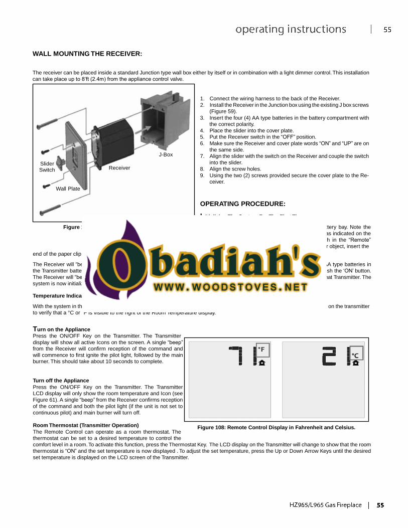
WALL MOUNTING THE RECEIVER:
The receiver can be placed inside a standard Junction type wall box either by itself or in combination with a light dimmer control. This installation
can take place up to 8’ft (2.4m) from the appliance control valve.
Slider
Switch Receiver
Wall Plate
J-Box
1. Connect the wiring harness to the back of the Receiver.
2. Install the Receiver in the Junction box using the existing J box screws
(Figure 59).
3. Insert the four (4) AA type batteries in the battery compartment with
the correct polarity.
4. Place the slider into the cover plate.
5. Put the Receiver switch in the “OFF” position.
6. Make sure the Receiver and cover plate words “ON” and “UP” are on
the same side.
7. Align the slider with the switch on the Receiver and couple the switch
into the slider.
8. Align the screw holes.
9. Using the two (2) screws provided secure the cover plate to the Re-
ceiver.
Figure 107: Wall Mounting the Receiver.
OPERATING PROCEDURE:
Initializing The System For The First Time
Install the four (4) AA batteries into the receiver battery bay. Note the
polarity of the battery and insert into the battery bay as indicated on the
Battery cover (+/-). Place the 3-position slider switch in the “Remote”
position. Using the end of a paper clip, or other similar object, insert the
end of the paper clip into the hole marked “PRG” on the Receiver front cover.
The Receiver will “beep” three (3) times to indicate that it is ready to synchronize with a Transmitter. Install the three (3) AAA type batteries in
the Transmitter battery bay, located on the base of the Transmitter. With the batteries already installed in the Transmitter, push the ‘ON’ button.
The Receiver will “beep” four (4) times to indicate the Transmitter’s command is accepted and sets to the particular code of that Transmitter. The
system is now initialized.
Temperature Indication Display
With the system in the “OFF” position, press the Thermostat Key and the Mode Key at the same time. Look at the LCD screen on the transmitter
to verify that a °C or °F is visible to the right of the Room Temperature display.
Turn on the Appliance
Press the ON/OFF Key on the Transmitter. The Transmitter
display will show all active Icons on the screen. A single “beep”
from the Receiver will confirm reception of the command and
will commence to first ignite the pilot light, followed by the main
burner. This should take about 10 seconds to complete.
Turn off the Appliance
Press the ON/OFF Key on the Transmitter. The Transmitter
LCD display will only show the room temperature and Icon (see
Figure 61). A single “beep” from the Receiver confirms reception
of the command and both the pilot light (if the unit is not set to
continuous pilot) and main burner will turn off.
Room Thermostat (Transmitter Operation)
The Remote Control can operate as a room thermostat. The
thermostat can be set to a desired temperature to control the
Figure 108: Remote Control Display in Fahrenheit and Celsius.
comfort level in a room. To activate this function, press the Thermostat Key. The LCD display on the Transmitter will change to show that the room
thermostat is “ON” and the set temperature is now displayed . To adjust the set temperature, press the Up or Down Arrow Keys until the desired
set temperature is displayed on the LCD screen of the Transmitter.
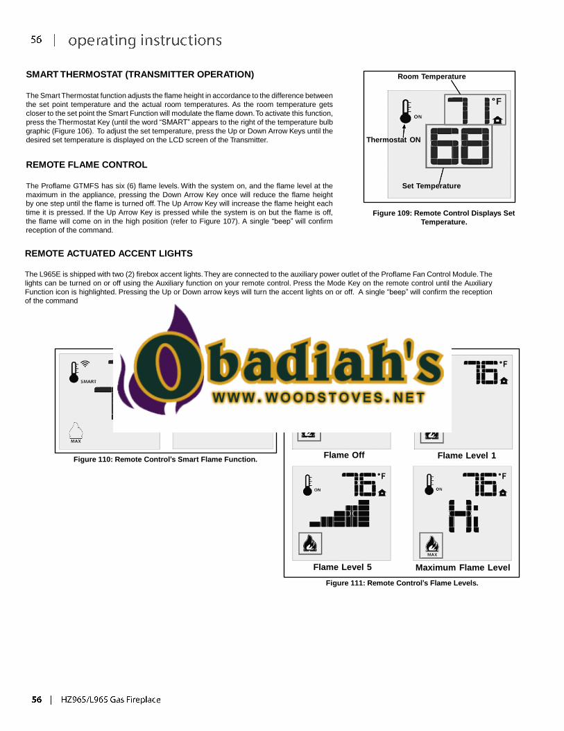
SMART THERMOSTAT (TRANSMITTER OPERATION)
The Smart Thermostat function adjusts the flame height in accordance to the difference between
the set point temperature and the actual room temperatures. As the room temperature gets
closer to the set point the Smart Function will modulate the flame down. To activate this function,
press the Thermostat Key (until the word “SMART” appears to the right of the temperature bulb
graphic (Figure 106). To adjust the set temperature, press the Up or Down Arrow Keys until the
desired set temperature is displayed on the LCD screen of the Transmitter.
REMOTE FLAME CONTROL
The Proflame GTMFS has six (6) flame levels. With the system on, and the flame level at the
maximum in the appliance, pressing the Down Arrow Key once will reduce the flame height
by one step until the flame is turned off. The Up Arrow Key will increase the flame height each
time it is pressed. If the Up Arrow Key is pressed while the system is on but the flame is off,
the flame will come on in the high position (refer to Figure 107). A single “beep” will confirm
reception of the command.
REMOTE ACTUATED ACCENT LIGHTS
Room Temperature Thermostat ON
Set Temperature
Figure 109: Remote Control Displays Set
Temperature.
The L965E is shipped with two (2) firebox accent lights. They are connected to the auxiliary power outlet of the Proflame Fan Control Module. The
lights can be turned on or off using the Auxiliary function on your remote control. Press the Mode Key on the remote control until the Auxiliary
Function icon is highlighted. Pressing the Up or Down arrow keys will turn the accent lights on or off. A single “beep” will confirm the reception
of the command
Figure 110: Remote Control’s Smart Flame Function. Flame Off Flame Level 1
Flame Level 5 Maximum Flame Level
Figure 111: Remote Control’s Flame Levels.
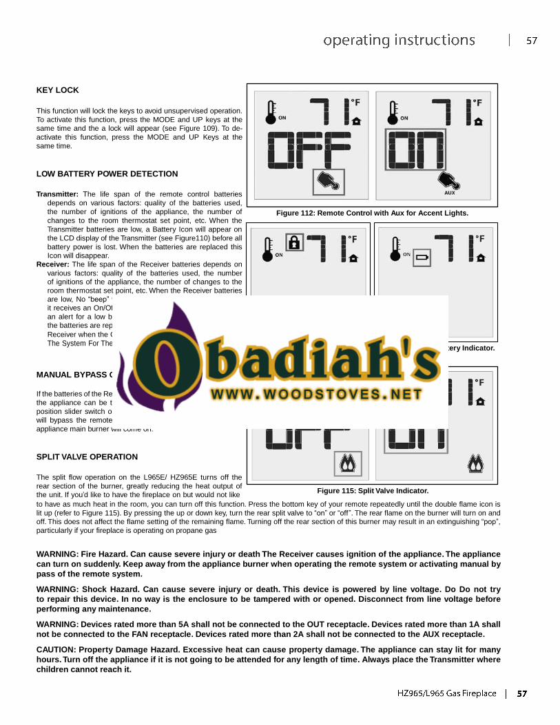
KEY LOCK
This function will lock the keys to avoid unsupervised operation.
To activate this function, press the MODE and UP keys at the
same time and the a lock will appear (see Figure 109). To de-
activate this function, press the MODE and UP Keys at the
same time.
LOW BATTERY POWER DETECTION
Transmitter: The life span of the remote control batteries
depends on various factors: quality of the batteries used,
the number of ignitions of the appliance, the number of
changes to the room thermostat set point, etc. When the
Transmitter batteries are low, a Battery Icon will appear on
the LCD display of the Transmitter (see Figure110) before all
battery power is lost. When the batteries are replaced this
Icon will disappear.
Receiver: The life span of the Receiver batteries depends on
various factors: quality of the batteries used, the number
of ignitions of the appliance, the number of changes to the
room thermostat set point, etc. When the Receiver batteries
are low, No “beep” will be emitted from the Receiver when
it receives an On/Off command from the Transmitter. This is
an alert for a low battery condition for the Receiver. When
the batteries are replaced the “beep” will be emitted from the
Receiver when the ON/OFF Key is pressed (See Initializing
Figure 112: Remote Control with Aux for Accent Lights.
The System For The First Time).
MANUAL BYPASS OF THE REMOTE SYSTEM
If the batteries of the Receiver or Transmitter are low or depleted,
the appliance can be turned on manually by sliding the three
position slider switch on the Receiver to the ON position. This
will bypass the remote control feature of the system and the
appliance main burner will come on.
SPLIT VALVE OPERATION
Figure 113: Remote Control
Locked.
Figure 114: Low Battery Indicator.
The split flow operation on the L965E/ HZ965E turns off the
rear section of the burner, greatly reducing the heat output of
the unit. If you’d like to have the fireplace on but would not like
Figure 115: Split Valve Indicator.
to have as much heat in the room, you can turn off this function. Press the bottom key of your remote repeatedly until the double flame icon is
lit up (refer to Figure 115). By pressing the up or down key, turn the rear split valve to “on” or “off”. The rear flame on the burner will turn on and
off. This does not affect the flame setting of the remaining flame. Turning off the rear section of this burner may result in an extinguishing “pop”,
particularly if your fireplace is operating on propane gas
WARNING: Fire Hazard. Can cause severe injury or death The Receiver causes ignition of the appliance. The appliance
can turn on suddenly. Keep away from the appliance burner when operating the remote system or activating manual by
pass of the remote system.
WARNING: Shock Hazard. Can cause severe injury or death. This device is powered by line voltage. Do Do not try
to repair this device. In no way is the enclosure to be tampered with or opened. Disconnect from line voltage before
performing any maintenance.
WARNING: Devices rated more than 5A shall not be connected to the OUT receptacle. Devices rated more than 1A shall
not be connected to the FAN receptacle. Devices rated more than 2A shall not be connected to the AUX receptacle.
CAUTION: Property Damage Hazard. Excessive heat can cause property damage. The appliance can stay lit for many
hours. Turn off the appliance if it is not going to be attended for any length of time. Always place the Transmitter where
children cannot reach it.
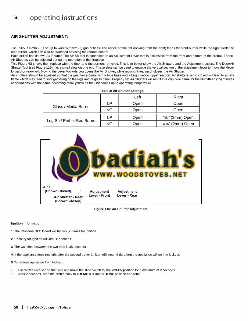
AIR SHUTTER ADJUSTMENT:
The L965E/ HZ965E is setup to work with two (2) gas orifices. The orifice on the left (looking from the front) feeds the front burner while the right feeds the
rear burner, which can also be switched off using the remote control.
Each orifice has its own Air Shutter. The Air Shutter is connected to an Adjustment Lever that is accessible from the front and bottom of the firebox. These
Air Shutters can be adjusted during the operation of the fireplace.
This Figure 68 shows the fireplace with the door and the burners removed. This is to better show the Air Shutters and the Adjustment Levers. The Door/Air
Shutter Tool (see Figure 116) has a small slots on one end. These slots can be used to engage the vertical section of the adjustment lever to move the klever
forward or rearward. Moving the Lever towards you opens the Air Shutter, while moving it rearward, closes the Air Shutter.
Air shutters should be adjusted so that the gas flame burns with a blue base and a bright yellow upper section. Air shutters set to closed will lead to a dirty
flame which may lead to soot gathering on the logs and/or glass panel. Properly set Air Shutters will result in a very blue flame for the first fifteen (15) minutes
of operations with the flame becoming more yellow as the unit comes up to operating temperature.
Table 2: Air Shutter Settings.
Left Right
Glass / Media Burner
LP Open Open
NG Open Open
Log Set/ Ember Bed Burner
LP Open 1/8” (3mm) Open
NG Open 1/16” (2mm) Open
Figure 116: Air Shutter Adjustment.
Ignition Information
1. The Proflame DFC Board will try two (2) times for ignition.
2. Each try for ignition will last 60 seconds.
3. The wait time between the two tries is 35 seconds.
4. If the appliance does not light after the second try for ignition (60 second duration) the appliance will go into lockout.
5. To remove appliance from lockout:
• Locate the receiver on the wall and move the slide switch to the <OFF> position for a minimum of 2 seconds.
• After 2 seconds, slide the switch back to <REMOTE> and/or <ON> position and retry.

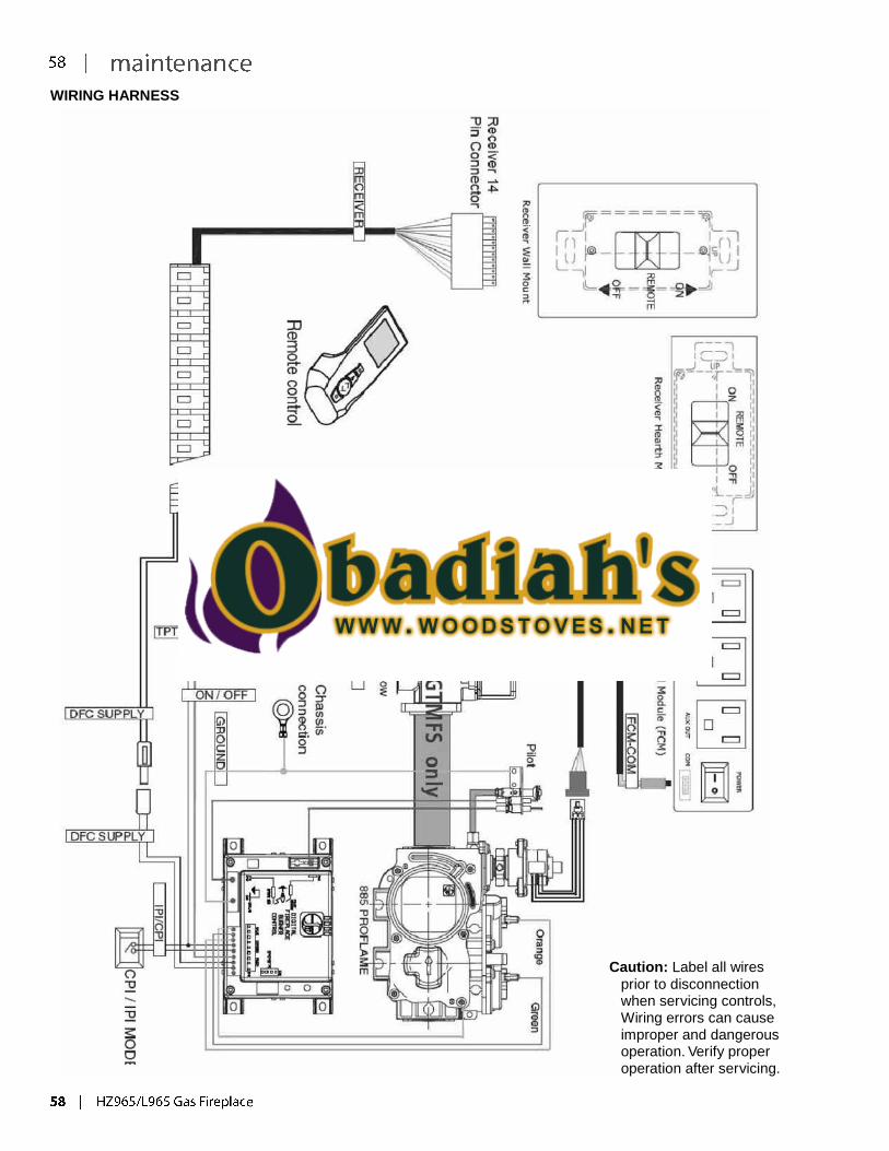
WIRING HARNESS
Caution: Label all wires
prior to disconnection when servicing controls, Wiring errors can cause improper and dangerous operation. Verify proper operation after servicing.
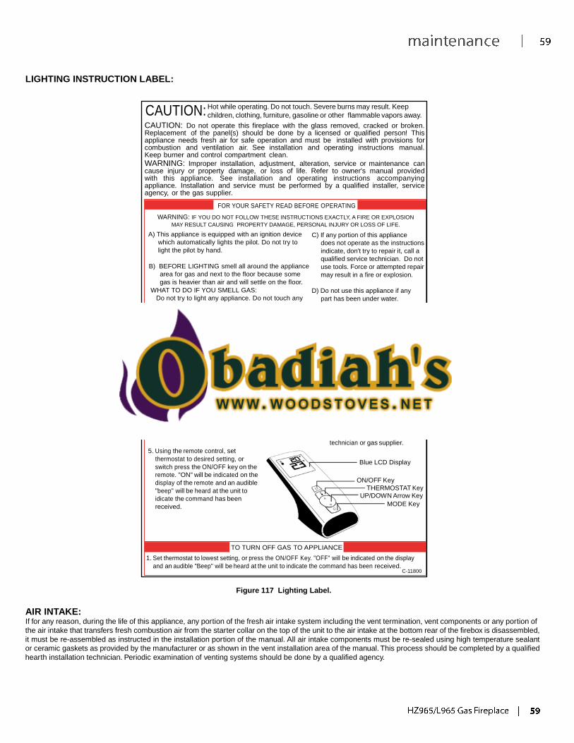
CAUTION:
LIGHTING INSTRUCTION LABEL:
Hot while operating. Do not touch. Severe burns may result. Keep
children, clothing, furniture, gasoline or other flammable vapors away.
CAUTION: Do not operate this fireplace with the glass removed, cracked or broken. Replacement of the panel(s) should be done by a licensed or qualified person! This appliance needs fresh air for safe operation and must be installed with provisions for combustion and ventilation air. See installation and operating instructions manual. Keep burner and control compartment clean.
WARNING: Improper installation, adjustment, alteration, service or maintenance can cause injury or property damage, or loss of life. Refer to owner's manual provided with this appliance. See installation and operating instructions accompanying appliance. Installation and service must be performed by a qualified installer, service agency, or the gas supplier.
FOR YOUR SAFETY READ BEFORE OPERATING
WARNING: IF YOU DO NOT FOLLOW THESE INSTRUCTIONS EXACTLY, A FIRE OR EXPLOSION
MAY RESULT CAUSING PROPERTY DAMAGE, PERSONAL INJURY OR LOSS OF LIFE.
A) This appliance is equipped with an ignition device
which automatically lights the pilot. Do not try to
light the pilot by hand.
B) BEFORE LIGHTING smell all around the appliance
area for gas and next to the floor because some
gas is heavier than air and will settle on the floor.
WHAT TO DO IF YOU SMELL GAS:
Do not try to light any appliance. Do not touch any
electrical switch: do not use any phone in your
building. Immediately call your gas supplier from a
neighbors' phone. Follow the gas suppliers
instructions. If you cannot reach your gas supplier,
call the fire department.
C) If any portion of this appliance
does not operate as the instructions
indicate, don't try to repair it, call a
qualified service technician. Do not
use tools. Force or attempted repair
may result in a fire or explosion.
D) Do not use this appliance if any
part has been under water.
Immediately call a qualified service
technician to inspect the appliance
and to replace any part of the
control system and any gas control
which has been under water.
OPERATING INSTRUCTIONS
1. STOP! Read the safety information above on this label.
2. Read the owner's manual including the section on "Remote
Control" operation.
3. Do not attempt to light the pilot by hand.
4. If you smell gas, STOP! Follow "B" in the safety
information above on this label. If you don't smell gas, go
to the next step.
5. Using the remote control, set
thermostat to desired setting, or
switch press the ON/OFF key on the
remote. "ON" will be indicated on the
display of the remote and an audible
"beep" will be heard at the unit to
idicate the command has been
received.
6. This appliance is equipped with a
completely automatic ignition and
lighting control. The control will
attempt to light the pilot several
timesif necessary. If it is
unsuccessful, it will discontinue
operations. If the appliance does
not operate, follow the
instructions "To Turn Off Gas To
Appliance" and call your service
technician or gas supplier.
Blue LCD Display
ON/OFF Key
THERMOSTAT Key UP/DOWN Arrow Key
MODE Key
TO TURN OFF GAS TO APPLIANCE
1. Set thermostat to lowest setting, or press the ON/OFF Key. "OFF" will be indicated on the display
and an audible "Beep" will be heard at the unit to indicate the command has been received. C-11800
Figure 117 Lighting Label.
AIR INTAKE: If for any reason, during the life of this appliance, any portion of the fresh air intake system including the vent termination, vent components or any portion of
the air intake that transfers fresh combustion air from the starter collar on the top of the unit to the air intake at the bottom rear of the firebox is disassembled,
it must be re-assembled as instructed in the installation portion of the manual. All air intake components must be re-sealed using high temperature sealant
or ceramic gaskets as provided by the manufacturer or as shown in the vent installation area of the manual. This process should be completed by a qualified
hearth installation technician. Periodic examination of venting systems should be done by a qualified agency.
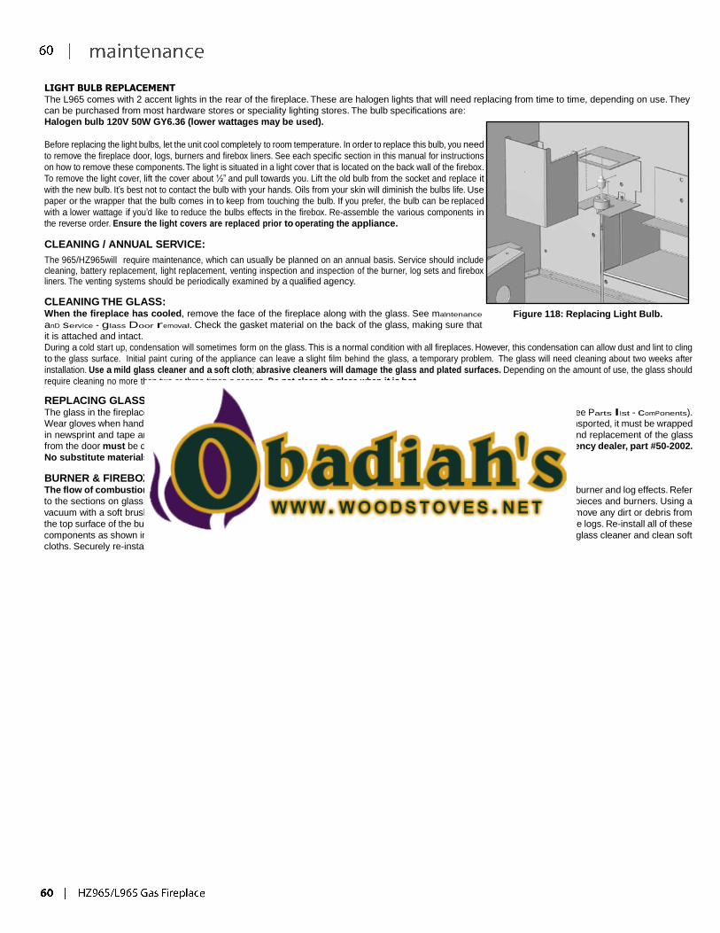
LIGHT BULB REPLACEMENT The L965 comes with 2 accent lights in the rear of the fireplace. These are halogen lights that will need replacing from time to time, depending on use. They
can be purchased from most hardware stores or speciality lighting stores. The bulb specifications are:
Halogen bulb 120V 50W GY6.36 (lower wattages may be used).
Before replacing the light bulbs, let the unit cool completely to room temperature. In order to replace this bulb, you need
to remove the fireplace door, logs, burners and firebox liners. See each specific section in this manual for instructions
on how to remove these components. The light is situated in a light cover that is located on the back wall of the firebox.
To remove the light cover, lift the cover about ½” and pull towards you. Lift the old bulb from the socket and replace it
with the new bulb. It’s best not to contact the bulb with your hands. Oils from your skin will diminish the bulbs life. Use
paper or the wrapper that the bulb comes in to keep from touching the bulb. If you prefer, the bulb can be replaced
with a lower wattage if you’d like to reduce the bulbs effects in the firebox. Re-assemble the various components in
the reverse order. Ensure the light covers are replaced prior to operating the appliance.
CLEANING / ANNUAL SERVICE:
The 965/HZ965will require maintenance, which can usually be planned on an annual basis. Service should include cleaning, battery replacement, light replacement, venting inspection and inspection of the burner, log sets and firebox liners. The venting systems should be periodically examined by a qualified agency.
CLEANING THE GLASS: When the fireplace has cooled, remove the face of the fireplace along with the glass. See maIntenance
anD servIce - glass Door removal. Check the gasket material on the back of the glass, making sure that
it is attached and intact.
Figure 118: Replacing Light Bulb.
During a cold start up, condensation will sometimes form on the glass. This is a normal condition with all fireplaces. However, this condensation can allow dust and lint to cling
to the glass surface. Initial paint curing of the appliance can leave a slight film behind the glass, a temporary problem. The glass will need cleaning about two weeks after
installation. Use a mild glass cleaner and a soft cloth; abrasive cleaners will damage the glass and plated surfaces. Depending on the amount of use, the glass should
require cleaning no more than two or three times a season. Do not clean the glass when it is hot.
REPLACING GLASS: The glass in the fireplace is a high temperature ceramic. If the glass is damaged in any way, a factory replacement is required (see Parts lIst - comPonents).
Wear gloves when handling damaged glass door assembly to prevent personal injury. When the glass door assembly is being transported, it must be wrapped
in newsprint and tape and/or a strong plastic bag. Do not operate with the glass front removed, cracked or broken. Removal and replacement of the glass
from the door must be done by a licensed or qualified service person. The glass must be purchased from an authorized Regency dealer, part #50-2002.
No substitute materials are allowed.
BURNER & FIREBOX CLEANING: The flow of combustion and ventilation air not to be obstructed. Periodic maintenance should include cleaning of the firebox, burner and log effects. Refer
to the sections on glass door removal, log and or burner installation to remove the glass door, log set (if equipped), burner trim pieces and burners. Using a
vacuum with a soft brush attachment, clean out any dust, lint or debris from the floor of the firebox. Using a soft brush, gently remove any dirt or debris from
the top surface of the burner. Using the same brush, gently brush away any carbon deposits that have built up on the surface of the logs. Re-install all of these
components as shown in the setup / installation portion of this guide. Clean both surfaces of the window glass using commercial glass cleaner and clean soft
cloths. Securely re-install the glass door onto the fireplace.
TROUBLESHOOTING
Problem Possible Cause Solution
Thermostat does
not work
The pilot flame has gone out · Turn it ON
The On/Off switch is turn to OFF
The thermostat is set too high · Set the thermostat to a lower temperature
No spark
generation
Spark develops near the pilot assembly or
could occur onboard
· Check pilot assembly wiring
· Check for broken or poor connection from the sparker to the electrode
· Check for the spark shorting or arcing at other locations
· Check for defective sparker and spark electrode
No pilot flame
ignition
No spark from the igniter · See “no spark generation”
Air in the gas line
· It takes a while for all the air to purge out of the pilot before gas can reach the pilot
and ignite
Pilot gas pressure dropout upon main
burner gas valve opening
· Check gas mains supply and pressure
No gas flow out of the pilot burner
· Check gas valve wirings and connections to the board
· Check the pilot burner for obstruction
· Check the wirings and connections between the pilot assembly and the board
· Check the correct gas type settings on the valve and pilot burner assembly orifice
Pilot will not
remain lit
Problem with Flame Sensor circuit
· Check for proper connection of the Flame Sensor to the DFC board
· Check pilot for full flame impingement around Flame Sensor
· If flame is too small, check gas pressure, adjust pilot rate screw, check pilot head for
damage
· Ensure the ground wire is properly attached to the pilot mounting bracket
and that it is makes a good electrical connection.
Restrictor setting
· Use the correct restrictor setting for the venting configuration
Remote control
does not work
The pilot light has gone out · See “Pilot will not remain lit”
The remote is too far away from the heater · Use the remote closer to the heater
The remote control receiver is turned “OFF” · Check the remote control instructions
One of the two remote control or receiver
batteries are dead
· Replace the batteries
No reaction to
command
Receiver or transmitter batteries are low · Replace the batteries
A maximum number of failed ignitions or
flame restorations have been reached.
· Remove any possible blocking conditions. See “locking conditions”
· See how to reset the board from Lockout
No communication between the remote
control and the receiver
· Reprogram the transmitter to the receiver.
· Follow the initializing system for the first time
TROUBLESHOOTING
Problem Possible Cause Solution
Locking
conditions
Reset the Proflame DFC board
· Turn the system off by pressing the ON/OFF button on the transmitter
· After approximately 2 seconds press the ON/OFF button on the
transmitter again.
· In the manual flame control mode, use the down arrow button to reduce
the flame to off, indicated by the word OFF displayed on the transmitter
LCD screen.
· Wait approximately 2 seconds and press the up arrow button, the
ignition sequence will start.
· With the transmitter off, move the slider switch on the receiver to the
OFF position.
· Wait approximately 2 seconds and move the receiver slider switch to the
ON position.
Main burners will
not start
The pilot flame has gone out · See “Pilot will not remain lit”
The remote control is not working correctly · Replace the batteries
The thermostat is disconnected or set too
high
· Set the thermostat to a lower temperature
Problem with thermopile circuit
· Check gas line pressure
· Check wiring to thermostat for breaks
· Check for flame impingement on thermopile
Flame lifting
Leak in vent pipe · Check for leaks in vent connections
Improper vent configuration · Check vent configuration with manual
Terminal may be re-circulating flue gases
· Check to see if terminal is on correctly
· May need to install high wind termination cap.
· Contact dealer
Blue Flames
The heater has just been started
· Normal during start up: flame will yellow as the fireplace heats up
Improper air shutter adjustment
· Adjust air shutter – contact your dealer
Glass fogs up Normal condition: after the appliance warms
up the glass will be clear.
**Due to additives in gas, glass may get hazy during operation** Clean as
needed.
Flames are
burning “dirty” or
sooting
The logs or glasses are placed incorrectly
· Check log positioning
· Check level of glasses layout
Improper air shutter adjustment
· Increase primary air by opening the air shutter and/or by opening the
vent restrictor
· Check for proper venting and blockage of the vent termination
· See also “Burners will not remain lit”
Incorrect rating input
· Check manifold pressure and clock input rating for over-firing
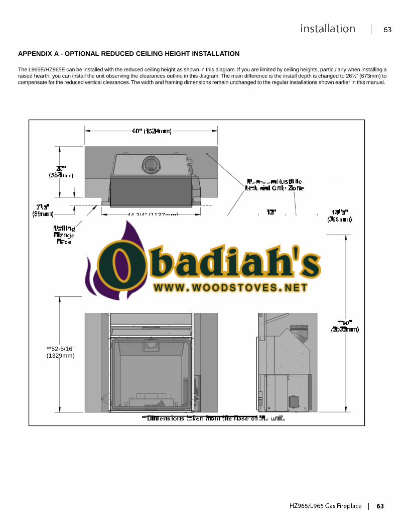
APPENDIX A - OPTIONAL REDUCED CEILING HEIGHT INSTALLATION
The L965E/HZ965E can be installed with the reduced ceiling height as shown in this diagram. If you are limited by ceiling heights, particularly when installing a
raised hearth, you can install the unit observing the clearances outline in this diagram. The main difference is the install depth is changed to 26½” (673mm) to
compensate for the reduced vertical clearances. The width and framing dimensions remain unchanged to the regular installations shown earlier in this manual.
44-3/4" (1137mm)
**52-5/16" (1329mm)
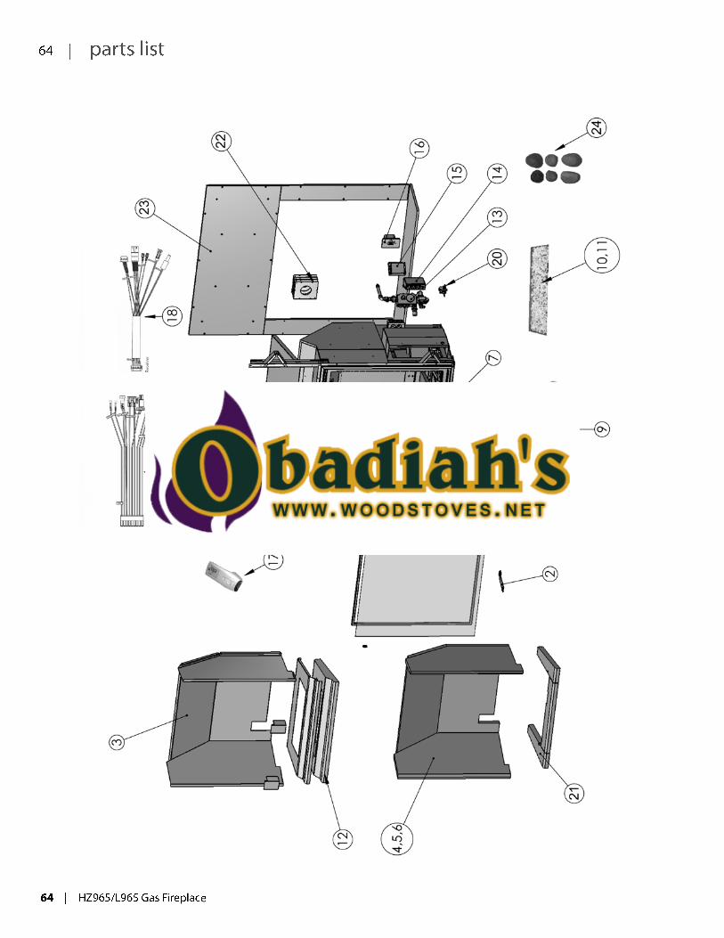
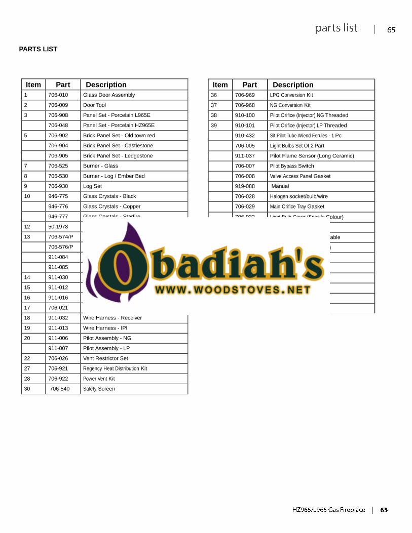
PARTS LIST
Item Part Description
36 706-969 LPG Conversion Kit
37 706-968 NG Conversion Kit
38 910-100 Pilot Orifice (Injector) NG Threaded
39 910-101 Pilot Orifice (Injector) LP Threaded
910-432 Sit Pilot Tube W/end Ferules - 1 Pc
706-005 Light Bulbs Set Of 2 Part
911-037 Pilot Flame Sensor (Long Ceramic)
706-007 Pilot Bypass Switch
706-008 Valve Access Panel Gasket
919-088 Manual
706-028 Halogen socket/bulb/wire
706-029 Main Orifice Tray Gasket
706-032 Light Bulb Cover (Specify Colour)
706-039 Door Gasket (20ft)
911-038 Spark Electrode W/ignitor Cable
706-003 Halogen Cycle (Pin Socket)
706-059 #55 Burner orifice - LP
706-060 #53 Burner orifice - LP
706-061 #45 Burner orifice - NG
706-062 #41 Burner orfice - NG
946-693 Stepper Motor - NG
946-694 Stepper Motor - LP
Item Part Description
1 706-010 Glass Door Assembly
2 706-009 Door Tool
3 706-908 Panel Set - Porcelain L965E
706-048 Panel Set - Porcelain HZ965E
5 706-902 Brick Panel Set - Old town red
706-904 Brick Panel Set - Castlestone
706-905 Brick Panel Set - Ledgestone
7 706-525 Burner - Glass
8 706-530 Burner - Log / Ember Bed
9 706-930 Log Set
10 946-775 Glass Crystals - Black
946-776 Glass Crystals - Copper
946-777 Glass Crystals - Starfire
12 50-1978 Refractory Burner Trim Black
13 706-574/P Valve Assembly - NG
706-576/P Valve Assembly - LP
911-084 Valve Only NG
911-085 Valve Only LP
14 911-030 Fan Controller Module
15 911-012 DFC (Digital Fireplace Control)
16 911-016 Remote Receiver
17 706-021 Transmitter
18 911-032 Wire Harness - Receiver
19 911-013 Wire Harness - IPI
20 911-006 Pilot Assembly - NG
911-007 Pilot Assembly - LP
22 706-026 Vent Restrictor Set
27 706-921 Regency Heat Distribution Kit
28 706-922 Power Vent Kit
30 706-540 Safety Screen
Regency Fireplace Products is the manufacturer of the Regency line of heating products. At Regency, our commitment to the highest level of quality and customer service is the most important thing we do. Each Regency stove is built on a tradition of using only the finest materials and is backed by our Exclusive Lifetime Limited Warranty to the original purchaser. With Regency, you’re not just buying a fireplace or stove, you’re buying a company with years of unequalled performance and quality.
Limited Seven (7) Year Warranty: Under this warranty, Regency Fireplace Products covers the fireplace or stove body and accessories against defects in materials and workmanship, for part repair or replacement for seven (7) years and subsidized* labour for the first three (3) years to the original purchaser. This Warranty covers: Firebox, Heat Exchanger, Steel Firebox Panels, Ceramic Logs & Panels, Burner, Ceramic Glass, Pedestals, Panels and Legs. Please see the exclusions and limitation section below as certain restrictions and exclusions apply to this warranty.
Limited Two (2) Year Warranty:
Under this warranty, Regency Fireplace Products covers: Gas Assembly, Pilot Assemblies, Flame Sensors, Flame Electrodes, Temperature Sensors, Remote Controls and Wire Harness against defects in materials and workmanship, for part repair or replacement for the first two (2) years and subsidized* labour for the first one (1) year to the original purchaser. Please see the exclusions and limitation section below as certain restrictions and exclusions apply to this warranty. *Subsidized according to job scale as predetermined by Regency.
To the Dealer When filling out a warranty claim, please complete the following information on an official warranty claim form: Customer information: Name, address and telephone number of purchaser and date of purchase. Dealer information: Date of installation, name of installer and dealer, serial number of the appliance, nature of complaint, defects or malfunction, description and part numbers of any parts replaced.
To the Distributor Sign and verify that work and information are correct.
Exclusions and Limitations: 1. This Warranty does not cover tarnish, discoloration or wear on the plating or paint. 2. This Warranty excludes wear and tear or breakage caused by cleaning, moving or service on log set and panels.
3. A qualified installer must install this stove or fireplace. This Limited Warranty covers defects in materials and workmanship only if the product has been installed in accordance with local building and fire codes; in their absence, refer to the owner’s manual. If the product is damaged or broken as a result of any alteration, wilful abuse, mishandling, accident, neglect, or misuse of the product, the Limited Warranty does not apply.
4. The stove must be operated and maintained at all times in accordance with the instructions in the Owner’s Manual. If the unit shows signs of neglect or misuse, it is not covered under the terms of this Warranty policy. Performance problems due to operator error will not be covered by the Limited Warranty policy.
5. As this is a heating appliance, some changes in colour of surface finishes may occur. This is not a flaw and as such is not covered under this warranty.
6. Some minor expansion, contraction, or movement of certain parts and resulting noise, is normal and not a defect and, therefore, is not covered under this Limited Warranty.
7. Misuse includes over-firing. Over-firing this appliance can cause serious damage and will nullify the Limited Warranty. 8. The Limited Warranty will cover glass thermal breakage only and will not cover misuse of the stove glass, including but
not limited to glass that is struck, has surface contaminates or has had harsh or abrasive cleaners used on it. 9. This warranty does not cover products made or provided by other manufacturers and used in conjunction with the
operation of this stove without prior authorization from Regency Fireplace Products The use of such products may
nullify the Limited Warranty on this stove. If unsure as to the extent of this Limited Warranty, contact your authorized Regency dealer before installation.
10. Regency Fireplace Products will not be responsible for inadequate performance caused by environmental conditions. 11. The Limited Warranty does not cover installation and operational related problems caused by downdrafts or spillage
caused by environmental conditions. Environmental conditions include but are not limited to nearby trees, buildings, roof tops, wind, hills, mountains, inadequate venting or ventilation, excessive offsets, negative air pressures or other influences caused by mechanical systems such as furnaces, fans, clothes dryers etc.
12. The Limited Warranty is void if:
a) The stove has been operated in atmospheres contaminated by chlorine, fluorine or other damaging chemicals. b) The stove is subject to submersion in water or prolonged periods of dampness or condensation. c) Any damage to the unit, combustion chamber or other components due to water, or weather damage which is the result of, but not limited to, improper chimney/venting installation. c) Salt air in coastal areas or high humidity can be corrosive to the finish; these environments can cause rusting. Damage caused by salt air or high humidity is not covered by the Limited Warranty.
13. Exclusions to the Limited Warranty include: injury, loss of use, damage, failure to function due to accident, negligence, misuse, improper installation, alteration or adjustment of the manufacturer’s settings of components, lack of proper and regular maintenance, alteration, or act of God.
14. The Limited Warranty does not cover damage caused to the fireplace or stove while in transit. If this occurs, do not operate the stove and contact your courier and/or dealer.
15. Limited Warranty does not extend to or include firebox paint, door or glass gaskets with damage caused by normal wear and tear, or exterior paint discoloration or chipping, worn gaskets, etc.
16. The Limited Warranty does not include damage to the unit caused by abuse, improper installation, or modification of the unit.
17. Damage to plated surfaces caused by fingerprints, scratches, melted items, or other external scores and residues left on the plated surfaces from the use of abrasive cleaners or polishes is not covered in this warranty.
18. The Limited Warranty does not cover tarnish, discoloration or wear on the plated surfaces.
19. The paint on the Metal Brick Liner may peel. This is due to the extreme conditions applied to the paint during normal usage. It is not a flaw and is not covered under warranty.
20. Regency Fireplace Products is free of liability for any damages caused by the fireplace or stove, as well as inconvenience expenses and materials. The Limited Warranty does not cover incidental or consequential damages.
21. The Limited Warranty does not cover any loss or damage incurred by the use or removal of any component or apparatus to or from the Regency fireplace or stove without the express written permission of Regency Fireplace Products and bearing a Regency Fireplace Products label of approval.
22. Any statement or representation of Regency products and their performance contained in Regency advertising, packaging literature, or printed material is not part of the Limited Warranty.
23. The Limited Warranty is automatically voided if the fireplace or stove’s serial number has been removed or altered in any way. If the stove is used for commercial purposes, it is excluded from the Limited Warranty.
24. No dealer, distributor, or similar person has the authority to represent or warrant Regency products beyond the terms contained within the Limited Warranty. Regency Fireplace Products assumes no liability for such warranties or representations.
25. Regency Fireplace Products will not cover the cost of the removal or re-installation of the stove, hearth, facing, mantels, venting or other components.
26. Subsidized labour to replace or repair items under this Limited Warranty will be covered per our warranty service fee reimbursement schedule. Labour rates are set per component and as such total labour costs may not be covered.
27. Regency Fireplace Products is not liable for freight or labour on any stove replaced in-fi eld and is not liable for travel costs for service work. In the event of in-home repair work, the customer will pay any in-home travel fees or service charges required by the Authorized Dealer.
28. At no time will Regency Fireplace Products be liable for any consequential damages which exceed the purchase price of the unit. Regency Fireplace Products has no obligation to enhance or modify any stove once manufactured (example: as a stove evolves, field modifications or upgrades will not be performed).
29. This Limited Warranty is applicable only to the original purchaser and it is non-transferable.
30. This warranty only covers Regency products that are purchased through an authorized Regency dealer.
31. If for any reason any section of the Limited Warranty is declared invalid, the balance of the warranty remains in effect and all other clauses shall remain in effect.
32. The Limited Warranty is the only warranty supplied by Regency Fireplace Products, the manufacturer of the stove.
All other warranties, whether expressed or implied, are hereby expressly disclaimed and purchaser’s recourse is expressly limited to the Limited Warranty.
33. Regency Fireplace Products and its employees or representatives will not assume any damages, either directly or indirectly, caused by improper usage, operation, installation, servicing or maintenance of this stove.
34. Regency Fireplace Products reserves the right to make changes without notice. Please complete and mail the warranty registration card and have the installer fill in the installation data sheet in the back of the manual for warranty and future reference.
35. Regency Fireplace Products is responsible for stocking parts for a maximum of seven (7) years after discontinuing the manufacture or incorporation of the item into its products. An exception to this would be if an OEM supplier is not able to supply a part.
36. It is the responsibility of the home owner to service and maintain the appliance. If any claims are sent to FPI, you may be asked for service records to ensure the appliance has been maintained. Retain all receipts for both service and/or parts which may have been replaced. Lack of service/maintenance is the largest contributor to malfunction of an appliance and is not covered under the terms of this warranty.

Register your Regency® warranty online
www.regency-fire.com
Reasons to register your product online today!
• View and modify a list of all your registered products.
• Request automatic email notification of new product updates.
• Stay informed about the current promotions, events, and special
offers on related products.
Installer: Please complete the following information
Dealer Name & Address:
Installer:
Phone #:
Date Installed:
Serial No.:
Liberty L965E Horizon HZI390E
© Copyright 2015, FPI Fireplace Products International Ltd. All rights reserved.
Printed in Canada