li - ntrs.nasa.gov conversion factor between thermal and work units ... viscosity .,-viii •...
TRANSCRIPT
lih
J
NASA TECHNICALi .?.
MEMORANDUM
J.
NASATMX64663
SUPPLEMENTTOTHEICRPGTURBULENTBOUNDARYLAYERNOZZLEANALYSISCOMPUTERPROGRAM
!(
.:: . •
;.../:i/ill
_: by Sa_oaki Omori, Kla_s W. Gross, and Alfred Krebsbach.:,;,:._: Astronautics Laboratory
-:_:,.!:(NASA-TH-X-64663) SUPPLEHENT TO THE ICRPG N72-253C;8 _,.:_.._.<::. TURBULENT BOUNDARY LAYER NOZZLE ANALYSIS
'::"::'::-_. COMPUTER PROGRAM S Omori, et al (NASA):-:.[-.: .:,.
","_!:!:!i'17 May 1972 289 p CSCL 2¢D UnclasG 2 29572
-... 3/1 "vg$_t.• !:.:: , May 17, 1972 _ 41@,4r_,": :._': [_ _w.K¢,c'b_-"_ _ "
_. NASA .,".._.
-y
GeorgeC. Narshall S?ace Flight Center :'
Narshal! SpaceFlight Center, Alabama
https://ntrs.nasa.gov/search.jsp?R=19720017658 2018-05-24T06:12:50+00:00Z
f
1FI(:tlNICAL R[.i_(Jl¢! %T AtIIII_..Rr) 1"II_, I.' PA,,i
I ;,f {'Id_'T 'l{I. I _, GOVLRh)MENT A( C|";%I(,H'4 NO. 3. t._['CII'_I{ NI _ (.AIAt t)G h('}. 1
..... TMX 6496:}............... _L4 lilt L ANt b ' tlii]llt. I b. R}'PORT hArE
Supplement to tile ICRPG Turbulent Boundary May 17, 1972
Layer Nozzle Analysis Computer Program 6. PERFORMING ORGANITATION :ODE
? AUTHOR t%) 8. PERFORMING ORGANIZATION REPORT
Satoaki Om¢tri,* Klaus W. Gross, Alfred Krebsbach
9. nf'RI:'ORMIN(', JRGANI:tATli'}N NAME: AND ADDRES5, lO. WORK UNIT NO.
George C. Marshall Space Flight Center I. CONTRACT OR GRANT NO.
,, Marshall Space Flight Center, Alabama 358121:3. TYPE OF" REPORT & PERIOD COVERED
1;2. SPoNSORIi'J(. AGEIICY I_AME AND ADDRESS
National Aeronautics and Space Administration Technical Memorandum
t Washington, D.C. 20546
14. SPONSORING AGENCY CODE
_--i,;_:";';;L_;_G"T'A"R'_"(,6rE-sPrepared by Astronautics Laboratory, Science and Engineering.
• ' * Dr. Omo_'i is a ,research associate with the National Research Council, National Academy of
[.___¢A_cn__e=Washin_on, D.C. .1_-.. _E::T_ :.CT
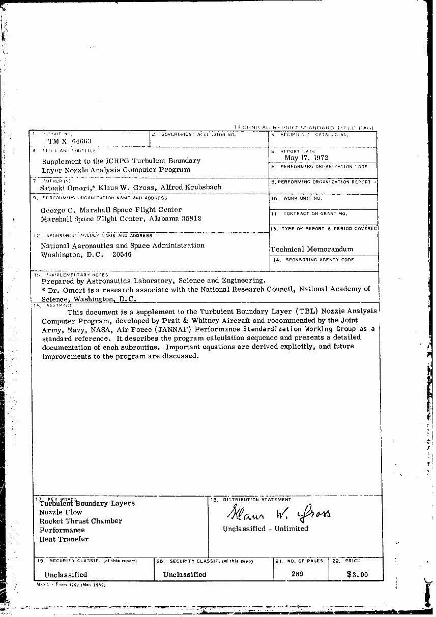
This document is a supplement to the Turbulent Boundary Layer (TBL) Nozzie Analysis
Computer Program, developed by-Pratt & Whitney Aircraft and recommended by the JointArmy, Navy, NASA, Air Fo=ce (JANNAF) Performance Standardization Working Group as astandard reference. It_describes the program calculation sequence and presents a detailed _ldocumentation of each subroutine. Important equations are derived explicitly, and future.....
improvements to the program are discussed. /m
17 I,E'¢ WORn_ 18. DISTRIBUTION STATEMENT
Turbulen{ Boundary Layers _(. _// _Nozzle Flow / 4,4,,_ a_i_Rocket Thrust Chamber 'Performance Unclassified - Unlimited
Heat Transfer _.
Unclassified I Unclassified 289 $3.00
, M:",I'(_ • F_,rm _202 (M=v 196': 0 it
_,__-= _.-.:..... _-7::_: ..... .... . .. . " ..... .7.]..;,L ' 2. ,, -- z_. _. =... __ ,C_'' --' ='..... 'J - - .....
00000001-TSA03
i
:!
i PRECLUDINGPAGP_BIZ_NK NOT FIT,MI_D
.. TABLEOFCONTENTS
.! Pagei
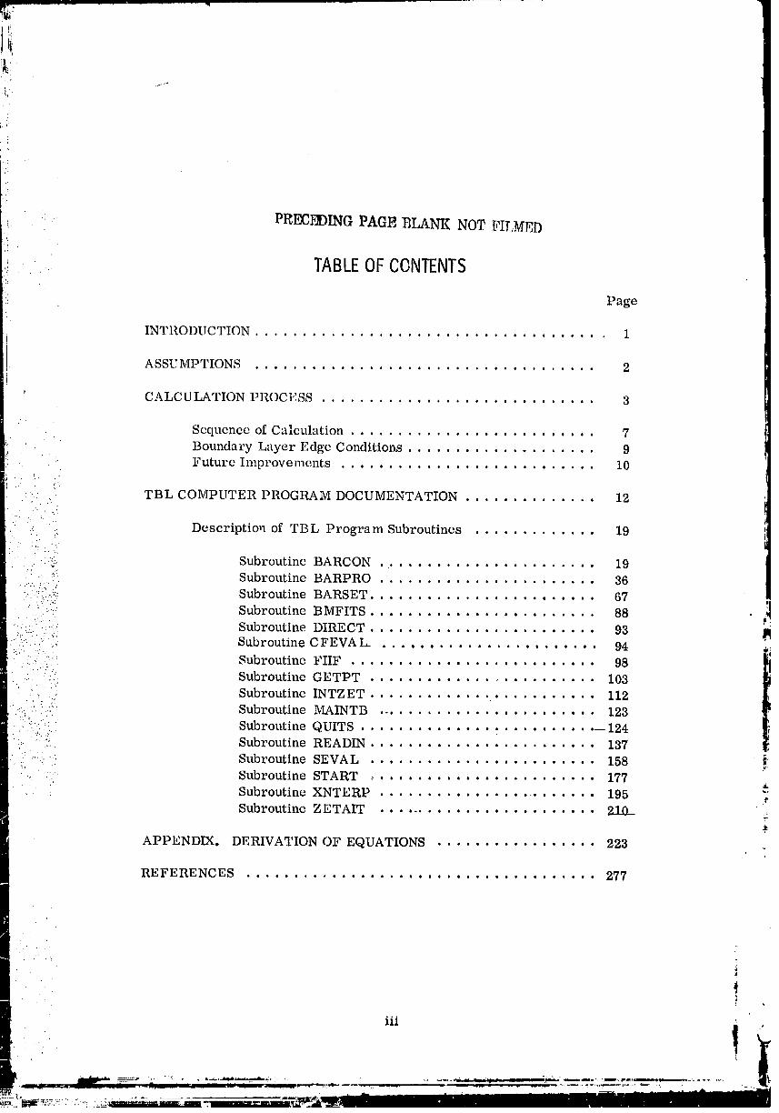
INTRODUCTION ..................................... 1
ASSUMPTIONS .................................... 2
#;
CALCULATION PROCESS ............................. 3
Sequence of Calculation.......................... 7
Boundary Layer Edge Conditions.................... 9Future Improvements ........................... 10
: TBL COMPUTER PROGRAM DOCUMENTATION .............. 12
., Description of TBL Program Subroutines ............. 19
_'. Subroutine BARCON 19.' " -°:" • • o o • I • • • • • • • • • • • • • • • • •
.....:, : i,' Subroutine BARPRO ....................... 36"-!?(!i? Subroutine BARSET ........................ 67 ,,,
• "- • i|
":i_: Subroutine BMFITS ....................... 88
'::,= :_: Subroutine DIRECT .................... • • • • 93
: :_'' : Subroutine CFEVAL. ............ 94
: ::,: Subroutine FIIF .................... • . • . , . 98.... Subroutine GETPT ....................... 103
1
: Subroutine INTZET ..................... 112
::::_ Subroutine MAINTB .................... 123:':::: Subroutine QUITS ...................... 124
:: :': Subroutine READIN .................... 137
.....• Subroutine SEVAL .................... 158 _'
Subroutine START ..................... 177Subroutine XNTERP ....................... 195
Subroutine ZETAIT ........................ 210__ _.
APPENDIX, DERIVATION OF EQUATIONS ................. 223
REFERENCES ..................................... 277
111 !
00000001-TSA04

LIST OF ILLUSTRATIONS
_ Figure Title Page
1. Calculation sequence used in thecomputer program ....................... 8
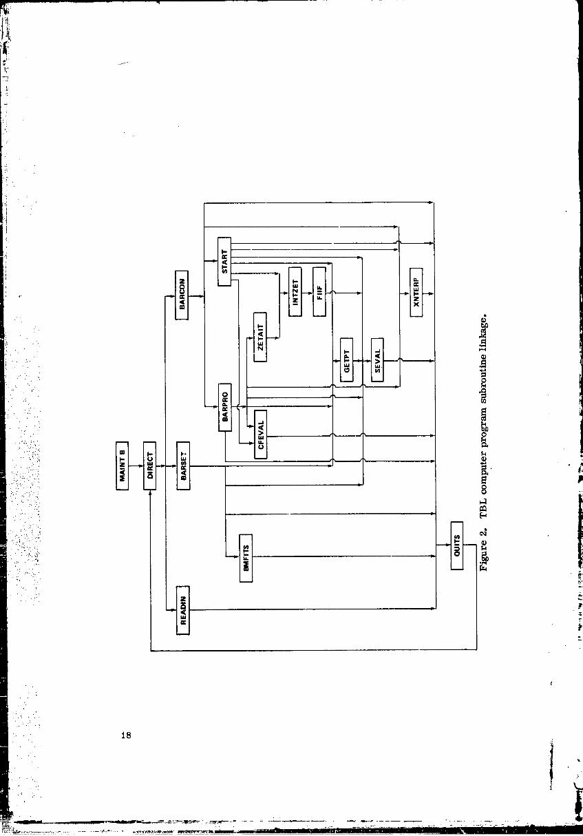
2. TBL computer program subroutinelinkage . ............................. 18
A-1. Coles' relation between Cf and CfR0 .......... 247
00000001-TSA05
I
LI STOFTABLES
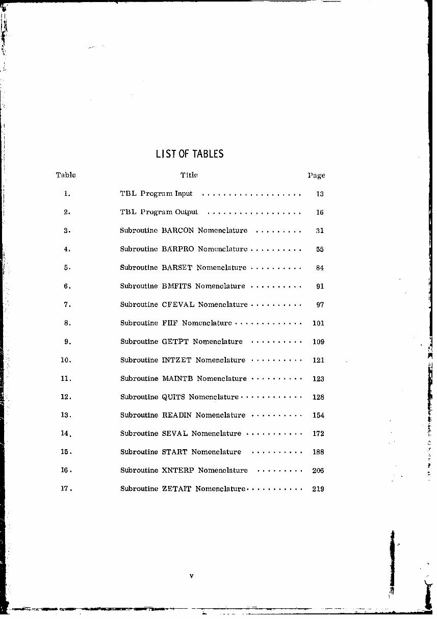
Table Title Page
• 1 TBL Program Input 13i • o o a o o o o 6 o o o • a • I o • o •
i
5 2. TBL Program Output .................. 16LI'
3. Subroutine BARCON Nomenclature ......... 31
4. Subroutine BARPRO Nomenclature .......... 55
5. Subroutine BARSET Nomenclature .......... 84
' 6. Subroutine BMFITS Nomenclature .......... 91
7. Subroutine CFEVAL Nomenclature .......... 97
8. Subroutine FIIF Nomenclature ............. 101
9. Subroutine GETPT Nomenclature .......... 109 ._
10. Subroutine INTZET Nomenclature .......... 121
11, Subroutine MAINTB Nomenclature .......... 123
12. Subroutine QUITS Nomenclature ............ 128!:i
13. Subroutine READIN Nomenclature .......... 154 _,• _,
14. Subroutine SEVAL Nomenclature ........... 172 : _'
15. Subroutine START Nomenclature .......... 188 :.T
16. Subroutine XNTERP Nomenclature ......... 206 :
17. Subroutine ZETAIT Nomenclature ........... 219
%,
00000001-TSA06

• LISTOFSYMBOLS
':_ A Area
a Spe¢,d of sound
t
i! Cf Skin friction coefficienti:
Cfa Adiabatic skin friction coefficient
C H Stanton number
C Specific heat at constant pressure.." p
::" _ C Specific heat at constant volume:: -. . =". V
D Drag
: "_ l_ Enthalpy flux...-_.. -:.:
• ....
::-" Fax , F Force in axial direction•..-.._...: X
:-_;_v. ,.: F , F Force in direction normal to axis:...::-:.: .:.: norm y _
.... '.. g Acceleration of gravity• •-..
': .... H Tota 1 entha lpy"..::.. '.:21".:
: :.-.:_:%:: : .....-.; h Static enthalpy within boundary layer
" _i"i_ h Total enthalpy within boundary layer _'O _"
h Heat transfer coefficlentg :
I Integra 1
J Conversion factor between thermal and work units
M Mach number at boundary layer outer edge
l_I Momentum flux• . . . .
.. • , .
t
vi
•._,,, i , ,, ,,-r-_ ":, i-lli ...... "il I -li
00000001-TSA07
.o..-
t¸
[
, LISTOFSYMBOLS(Continued)
; m Exponent in viseosity-temper&ture relation
Mass flow rate
_E Mean molecular, weig_htJ_
n Exponent in velocity and enthalpy profiles
n Interaction exponent in Stanton number equation
P Pressure
Pr Prandtl number
• Qw Integrated rate of heat transfer to the wall
q Specific heat transfer rateW
i:i ::ii! R Gas constant (_/CJl_)- :.." ;'.:
.•....,:!:. ..-.. R L Reynolds. number based on contour length
:_:;"ii"::: RT Recovery factor• ." • . "
• _ R Reynolds number based on axiallengthX
-:. -. ": .- ".
?:::!i.::ii(_' R 6 , Reynolds number based on displacement thickness%
.:'. ...
_. R 0 Reynolds number based on momentum thickness _!:.-...
R_ Reynolds number based on enerEy thickness -_
Universalgas constant
r Radius of the nozzle wall at x
S Entropy, length along the wall or (y/6) 1/n
T Temperature
J
vii
.°•_
.... • _, _ .,-,,,,,,, -
00000001-TSA08

.... LISTOFSYMBOLS(Continued)
t Temperature inside boundary layer
U Velocity at boundary layer outer edge
"_ Velocity within boundary laye-:
~ Internal energyU
w (y/A) 1/n
X Axial distance (contour length in appendix)
:- . y Distance from wall
z Axial length in appendixL:- :: :_,
,. c_ Angle of wall to axial direction
' i'i_:::i::!":!"::" fl Angle of wall to axial direction
_.:,::._.:." C"..:.:...... y Specific heat ratio
-. _..:..:. ::,.. A Temperature thickness
ii
-:..' :: '_:'" AF Thrust loss
.."_ :....:-......
•:"..,i::._.-.-.::,... 5 Velocity thickness i:
• .....' • '_:.. 5 * Displacement thickness • _._. ... ..
'" " " " " " th "5 ' Distance from n streamline to potential wall cp ._.
th _-.5 ' Distance from n streamline to real wallr
(A/6) 1/nt
0 Momentum thickness
Viscosity .,-
viii
• /
...." LISTOFSYMBOLS(Concluded)
1, Kinetic viscosity
p Density
•r Shear stress at the wallW
t:
¢ E nergy thickness
• " Subseript.s. . '.
::. ,. !: o Stagnation condition. _ • . .:':._.
.: aw Adiabatic wall.'; : :.
".. .- . ,
.,:. e Chamber stagnation• . . .
.." . . "'._
....•" .:.:_ e Boundary layer outer edge
"......: f F lu!d bulk:':'. " T -. ".. :*.':"
:...:"':. .... . -
:'::.: ::..: .: p Potential flow
: :: i.i' :(::: r Real flow
• . !- .:' :.,:'.,..,:.:._
:.: :! ,::. :: _ Boundary layer outer edge
• ......: • Conditions inside boundary layerf
,t
O0000001-TSAIO

TECIINICAL MEMORANDUM X- 64663
SUPPLEMENTTOT.HEICRPGTURBULENTBOUNDARYLAYERNOZZLEANALYSISCOMPUTERPROGRAM
INTRODUCTION
This document serves as a supplement to Reference 1 and containsan
additionaldetaileddescriptionof theTurbulent Boundary Layer (TBL) Nozzle
Analysis Computer Program, developedby Pratt & Whitney Aircraftand
recommended by theJointArmy, Navy, NASA_ Air Force (JANNAF) Perform-ance StandarizationWorking Group as a standard reference.
Among other lossesoccurringin a rocket thrust_hamber, theviscous
effectsinthe boundary layercontributesignificantlyto the performancedegradation. Itisthe objectiveofthisanalyticalmodel to determine the _
necessary boundary layerparameters which permit the calculationof.the
thrust deficiency.. In order to treat the boundary layer behavior.the edge ]
conditions, thewall temperature distribution, and the nozzle geometry must _be known. Results can only be obtained for a boundary layer developmentalong a solid-wall surface area without any film or transpiration coolant flow
introduction. Heat transfer calculations which are also performed in this
analysis are not very precise and have only a secondary effect on the perform-ance degradation.
This supplementary document starts with a description of the basic
calculation sequence. Then the necessary computer program input parametersand calculation options are characterized, followed by a summary of the analyt-ical results printed by the program. The subsequent section headed by a flow : _
chart showing the coordination of all subroutines in the calculation processcontains a detailed description of each subroutine. After a brief narrativetoutlining the purpose of the subroutine accompanied by important physical :equations, the subroutine from a programming aspect is presented. All
common blocks used in the subroutine, the subroutine calling, the subjectsubroutine, as well as the subroutines called by this subroutine, computer
library routines, and program built-in library routinest and the calling
sequence arc specified. The underlined parameters in the calling sequence
represent the terms solved for in the subroutine called. Then the step-by-step tcalculation process in accordance with the computer program listing is reported.The symbols used in the- expressions in the subroutine are listed in the front of ..
this report. In the appendix a detailed derivation of the important equations
1
00000001-TSA11
used in the analysis [ 1] is presented. This document in connection with
Reference 1 should provide the user of the subject computer program all
': necessary information to apply the program successfully or to incorporatemodifications for specific problems.
ASSUMPTIONSi
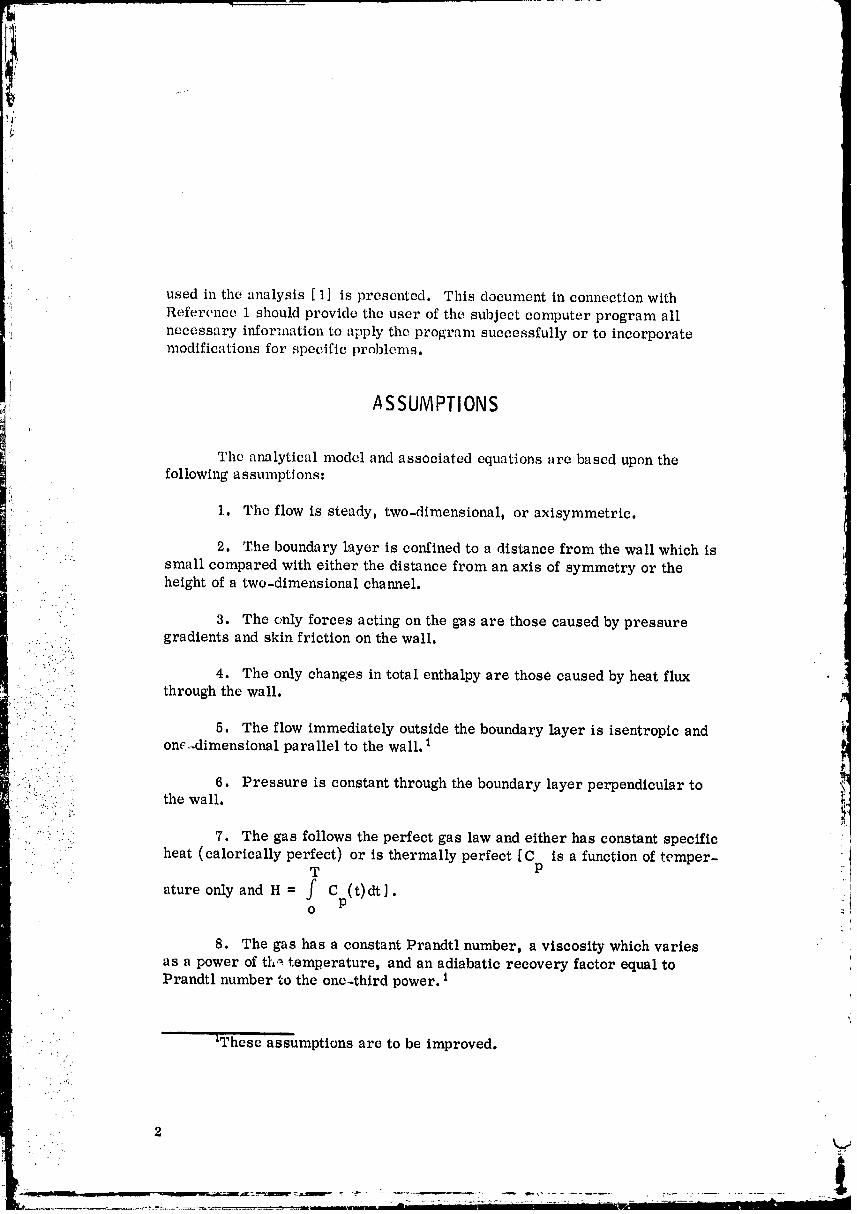
The analytical model and associated equations are based upon the
following a s sumptJ ons:
1. The flow is steady, two-dimensional, or axisymmetric.
2. The boundary layer is confined to a distance from the wall which is
" small compared with either the distance from an axis of symmetry or theheight of a two-dimensional channel.
3. The only forces acting on the gas are those caused by pressuregradients and skin friction on the wall.
•. :.:.:.:.:.::
• :• 4. The only changes in total enthalpy are those caused by heat flux•, ... •
.... : through the wall.i:::::7.: :
•: : 5. The flow immediately outside the boundary layer is isentropic and.... " one.-dimensional parallel to the wall. 1•-' . --•.
_ : : 6. Pressure is constant through the boundary layer perpendicular to t:!:.: the wall. _.
...., • 7. The gas follows the perfect gas law and either has constant specific_' .F
..... heat (calorically perfect) or is thermally perfect [C is a function of temper-T P
ature only and H = f Cp(t)dt ].O
8. The gas has a constant Prandtl number_ a viscosity which varies
as a power of th._ temperature, and an adiabatic recovery factor equal toPrandtl number to the one-third power. 1
..... 2These assumptions are to be improved.
l:!i
_ii!:
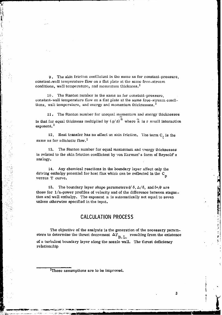
9. The skin friction coefficient is the same as for constant-pressure,
constant-wall temperature flow on a flat plate at the same free-stream
conditions, wall temperature, and momentum thickness. 2
10. The Stanton number is the same as for constant-pressure,constant-wall temperature flow on a flat plate at the same free-stream.condi-tions, waii temperature, and energy and momentum thicknesses. 2
11, The Stanton number for unequal momentum and energy thicknesses
" is that for equal thickness multiplied by (9/0)n where _ is _ small interaction
• exponent. 2
12. Heat transfer has no effect on skin friction. The term Cf is the:.. same as for adiabatic flow. 2
13. The Stanton number for equal momentum and energy thicknesses
::: is related to the skin friction coefficient by yon Karman' s form of Reynold' sanalogy.
...... "_ 14. Any chemical reactions in the boundary layer affect only theY driving enthalpy potential for heat flux which can be reflected in the C !|
: !: p.... .i. • versus T curve.
:::i:_i: 15. The boundary layer shape parameters e/ _, _/6, andS,/0 are
.:• ' those for 1/n-power profiles of velocity and of the difference between stagna- L:_i• ,_ tion and wall enthalpy. The exponent n is automatically set equal to seven,..... _ unless otherwise specified in the input.
: .... CALCULATIONPROCESS " ;;g..
'1"
The objective of the analysis is the generation of the necessary param-
eters to determine the thrust decrement AFB. L. resulting from the existence
of a turbulent boundary layer along the nozzle wall. The thrust deficiency ,relation_hip
2These assumptions are to be improved.
3
00000001-TSC01
3,.
(2) ( )AFB, L. = 7rrpu20 cos a 1 - _-7 exitexit
which is presently not included in the computer program basically represents
the summation of the shear stress along the nozzle wall. Ilowever, thissummation can be correlated to nozzle exit flow par'_meters as the derivation
in the appendix indicates. In the previous equation only the momentum thick-
ness 0 and di_placcment thickness 6 * arc representative expressions
resulting from a boundary layer analysis, while the remaining parametersidentify potential flow conditions at the boundary layer edge.
The heat transfer rate to the nozzle wall at any local station, expressed
by the followia_g relationship
qw = CHPeUc(Haw - Hw) '
is another important result of this program. Its integrated quantity along the
wall indicates the energy which is either lost or recovered, depending on thecooling concept app.l.ied_, .
Subsequently, the important equations _re listed which must be solved
within the computer program.::.!
: Momentum equation _I
dO _ 1+ -0 e + + __
dx 2 U dx PeUe dx r dx '
Energy equation _',
(. -. )j -.d_b= CH aw wd"_ H : H 1 + kdx] ,_o w _
[ U) 1 dr 1 dH ] . .:
_ _ 1 d(Pe e + wdx r dx H -H dx 'PeUe o w
where
Displacement thickness:
6
= f - dy ,D_
o ! -.
J4
00000001-TSC02
_: Momentum thickness:
':! 8,
0=f 0u 1 _m dy ,o PeUe Ue
Energy thickness:m,
6'
r ( ho- HW dy- . _b = fo PeU---_ - Ho HwJ
' The power law profiles assuming _ 1/7 exponent are used for the. .,...
.....:: velocity and enthalpy profiles.. .'-.... ..
t
• ...:.. U e
• .:..:.:.".." : .. .
• :;::../.............._--= 1 for y >8 ;e
....,. . . _ .. .
. : _:, o w = (y) fory < A ;•. :"= "' H -H -. - . ..
0 W
"....... .. : .- ...... :11O W
= 1 for y > A......:. i'.:. _:: H - H ":, o w
• . With a given nozzle contour r = r(x), the free-stream velocity Ue
and density Pe are calculated at each axial distance x using the input Mach
number Me = Me(X) . The skin friction coefficient Cf and Stanton number CHare also obtained using empirical relationships,
11
1
,.. . .
i_ _
tD
ili_-7 • "z -_ ' -- " i li I I i I l " - I
00000001-TSC03
Computation of the following pa ra meters
1. Momentum thickness 0 = 0 (x),
i 2. Energy thickness _ :-_@ (x),
3. Displacement thickness _ * = 5 * (x),L
4. Temperature thickness A = A (x),
5. Velocity thickness 5 _ 6 (x),
6. Temperature or density distribution at the boundary layer edge
7. Adiabh%ic wall enthalpy H = H (x)aw aw
is performed by using the ideal gas equation
P = p_T
and entha!py relations
T
H = f C(t)dt,_O
H = C T, for calorically perfect gas,P
oru 2
H = n + (Pr)1/3 weaw 2 gJ '
U2 , -
-_o--h+ 7}5-gj.
'/' a,
i,i_ ';6
00000001-TSC04
i
Sequenceof Calculation
All equations used in the calculation process are presented in Reference
1. In the appendix of this document a detailed derivation of important equa-tions is given, and the equation number is related to the same one used inReference 1. Subsequently, the calculation sequence used in the computer
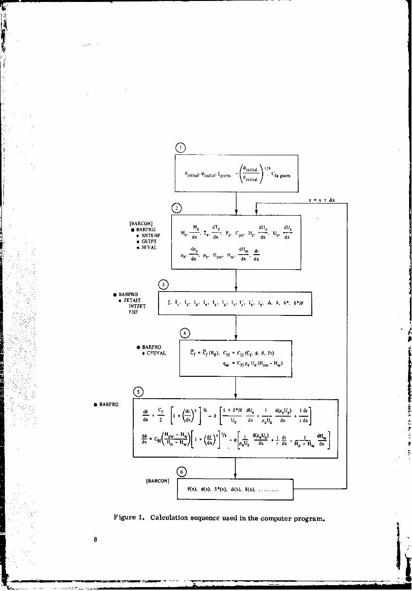
program is outlinc'd and schemqtically shown in Figure 1.
1. Input values such as thrust elm.tuber operating conditions and
, and Pr) the nozzle contour r = r (x),stagnation properties (Po' To' To' /_o
the free-stream Mach number distribution M = M (x), and the specifice e
heat versus temperature relationship C = C (t) are necessary require-P P
ments. To start the computer program calculation, initial assumptions for
the momentum and energy thickness must be made, and appropriate optionindicators must be set.
dM dTe e
2. The following intermediate values Me, d--'_" Te' "_"' Pe '_ Cpe'
dH dUe dp e dHw
He' --_' Ue' --_x' Pe' "_' /Ze' Haw' Hw' and ---_- are then internally e,
:' determined by _he program using the associated equations outlined in the .-_:: ::!"
following section.
•3. The important parameter _: {-._--} , varied internally during
\--],-..
iteration loops, is utilized to calculate the boundary layer thicknesses such as
• . A, 5, 5", and 5"/0 at a specific location of the nozzle wall.
• With empirical relationships the friction coefficient _f and the :=,_'n _ _ 4
Stanton number Ctt are determined by iteration. These parameters must _
be known to cah,,_latc the heat transfer rate qw"
.
5. Now the Runge-Kutta -G ill method is applied to predict an energyand momentum thickness (_ and 0) as a new aploroximation for a new down-stream location x _-- x + Ax.
,o
7
00000001-TSC05
i!i ......I_ _!_
= /_jnilj:l___.._l _ I/ll
Oi,lilial' @initial' _guess \Oinilia I / ' Cfa gucss
®
[BARCON] I ]
O(x), ¢Kx), 6*(x), _(x), 8(x) .........
• _ " Figure 1. Calculation sequence, used in the computer program.
' ":' i
O0000001-TSC06

I,:
6. The previously outlined computation procedure is repeated using theI,
' initial approximations from paragraph 5.
In Figure 1 the previously outlined steps are shown in a diagram format.
On the left-hand side of each step, tb.e calling subroutine (in brackets), the
executing subroutine (marked by a solid bubble), and the assisting subroutinesduring the calculation process are outlined.
BoundaryLayerEdgeConditions
i. From the chamber stagnation data, the Iviaeh number distribution along
the nozzle wall and specific heat versus temperature relationship additional
static flow and thermodynamic properties 0,e, Te, Pe' Ue' %) must be gener-._ , '.:;'
ated to permit the calculation of various integrals as shown in Block 3 of Figure1. The local specific heat is determined in subroutine GETPT. At any local
-- : '/( -- /i"":
:. dMe
. station x the Mach number M , its derivative --_-, and the first derivative of
1: i'i!!::;t!"i:: Te, dT e/dX are obtained from. a quintic spline interpolation routine. In... "/ . .._
::.. :'.... : addition, using the definition of enthalpy,,.:... .: :' ..-.,_
:. :: .i:::.::: U 2
":::': " H = H + e
. " . ': : o e 2gJ'• .. -....
, .... the free-stream velocity is calculated
• .t.; .- • - . •
. = "_'/-2Jg (H - He) ,• :.., .: ",: .i" Ue o@
.... ' .:.: _:: ; where _
•* "" .v-
Te 7
He = H.1 + f Cp(t)__ dt,-T.
1
Differentiating the previous equation with respect to x, one obtains
dH dT ,'e e
_ - C• " dx pe "_'"
i I :
00000001-TSC07

I •
'i Differentiating the original enthalpy equation results in
dU dtt_ e e:: U -
e dx dx gJ •t
! Substituting the riglv:-hand term by the previous expressiont the1folh)wing L_uatton used in Block 2 of Figure 1 is obtained°
dU d're o
U C _ gJ.e "_x = - pc dx
i) The derivative of the free-stream density Pe = p (x) is determinedi: by means of the ideal gas equation e
i
e
: .:=i Pe R Te
.... If the density change is considered to be very small for a small distance
;_ ;:,:-i:) Ax along the boundary layer edge, the derivative can be approximated by: .:; .," .:
J
.=:(:.::! do e Pe(X) - Pe(X - Ax) ]m:.:)..... • _i_: _ =dx Ax •
".'.• .. ..
: : In order to solve the momentum equations in step 5 of the preceding. , . . . ..
_ ...... : section (Sequence of Calculation), the value of 6"/0 must be given• Equa-
:' i!:i:._:'i::_:.• : ::: tions (89) and (119) of Reference 1 are used to determine these quantities.
• :;: " ._,, _..
•.:........ Future Improvements
1. The TBL program uses only the free-stream Mach number M as re i,
a function of axial nozzle length to describe the boundary layer edge condition. ' "-All the other important thermodynamic and fluid dynamic properties are calcu-lated from the Mach number profile, Yurthermore, the molecular weight_represented by the specific gas constant_ is a.ssumed to remain constantthroughout the calculation process.
00000001-TSC08
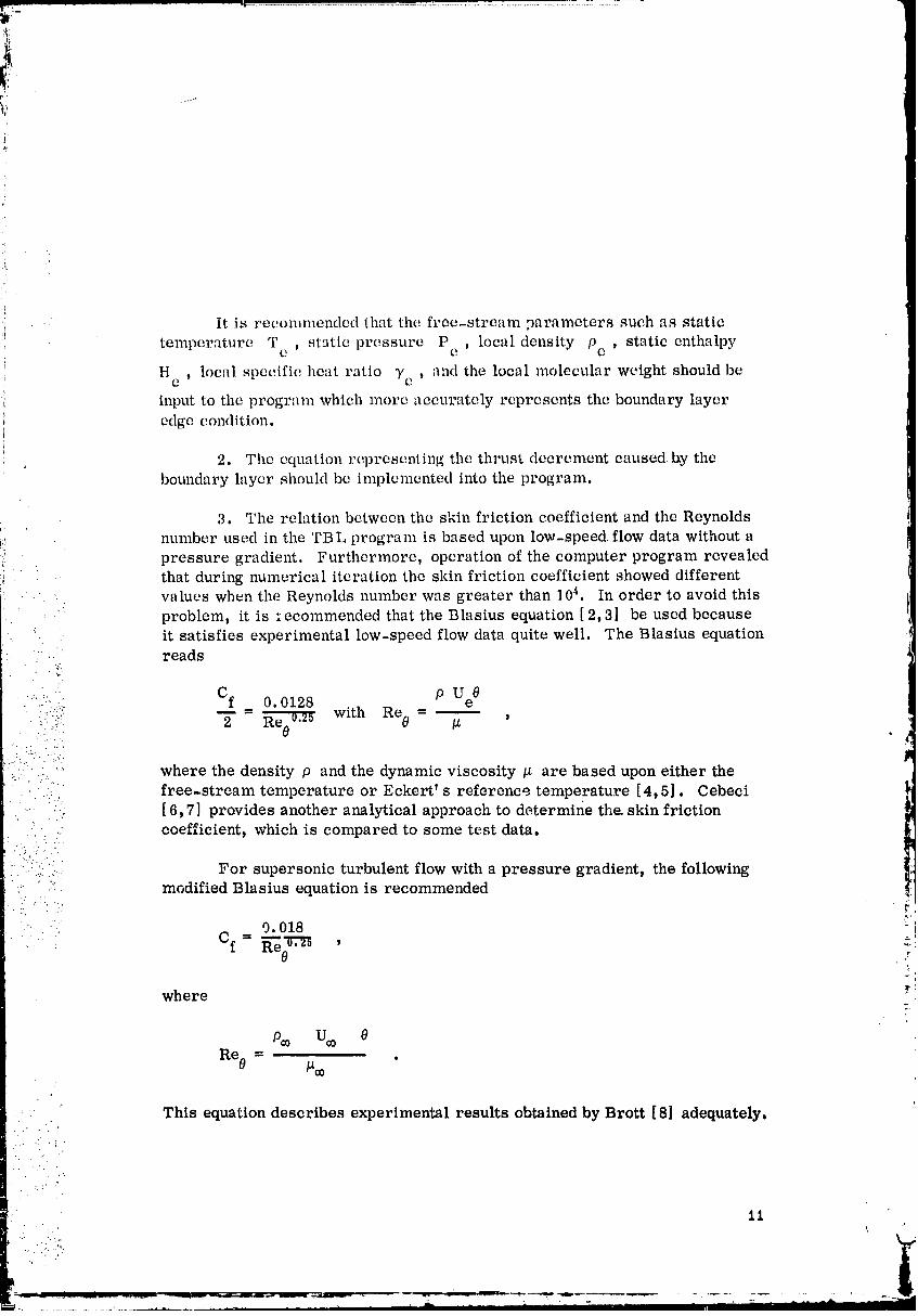
• " It is recommended that the free-stream parameters such as static
temperature T static pressure Pc ' local density Pc static enthalpvC _ t
H local specific heat ratio 7e and the local molecular weight should be
input to the program which more accurately represents the boundary layer
edge condition,
2. The equation representing the thrust decrement caused lay the
boundary layer shouhl bc implemented into the program.
3. The relation between the skin friction coefficient and the Reynolds
!!_ number used in the TBL program is based upon low-speed flow data without aI.!. pressure gradient. Furthermore, operation of the computer program revealed.... that during numerical iteration the skin friction coefficient showed different
values when the Reynolds number was greater than 104. In order to avoid this
. problem, it is :ecommended that the Blasius equation [ 2, 3] be used because
• it satisfies experimental low-speed flow data quite well. The Blasius equation' .. reads
• Cf 0• .::.:::. _ 0. 0128 P Ue
:..:.:'"" 2 Re0_i r with Re 0 = /_ ' '4• : (..!-. ,_
where the density p and the dynamic viscosity /_ are based upon either the• free-stream temperature or Eckert' s reference temperature [4,5]. Cebeci
• . . • :' ,.
-- [6,7] provides another analytical approach to determine the. skin frictioncoefficient, which is compared to some test data.
::.. :.:.,.: For supersonic turbulent flow with a pressure gradient, the following'- " .:':. modified Blasius equation is recommended
N'
'- 9.018
•" Cf- ,
where _"
Po0 U¢0 0
Re0 = /_¢0 '
• This equation describes experimental results obtained by Brott [8] adequately.
11
00000001-TSC09

i
:!'i
_: 4. The presently used constant power law associqLed with the velocityand enthalpy does not adequately represent the flow condition especially at highMuch numbers and for a coole,d wall [8-10]. Therefore, it is recommendedthat a vnriable exponent 1/n as a function of the M'lch number be incorpo-
! rated into the e,'dcuhltion process.
5. Presently a constant I)randtl nunfi)er is input to the program. Since
,: the specific heat and the moleeulnr weight change during the expansion processin u rocket nozzle, it is recommended that the Pr:mdtl number be internallycalculated according to the equation
pC CPr - P - P
kC + --5R'
• . : p 4
• . where the specific gas constant
a --..'- _)_
•.'... _' ..." .:*'.'- f
• ::::" ' where ;_ represents the universal gas constant and 91_ the mean molecular....:: .:.,....': weight.
l:i .... TBLCOMPUTERPROGRAMDOCUMENTATION
• i.. "??.,..,..-: ..... .. -_..:,. • . . .
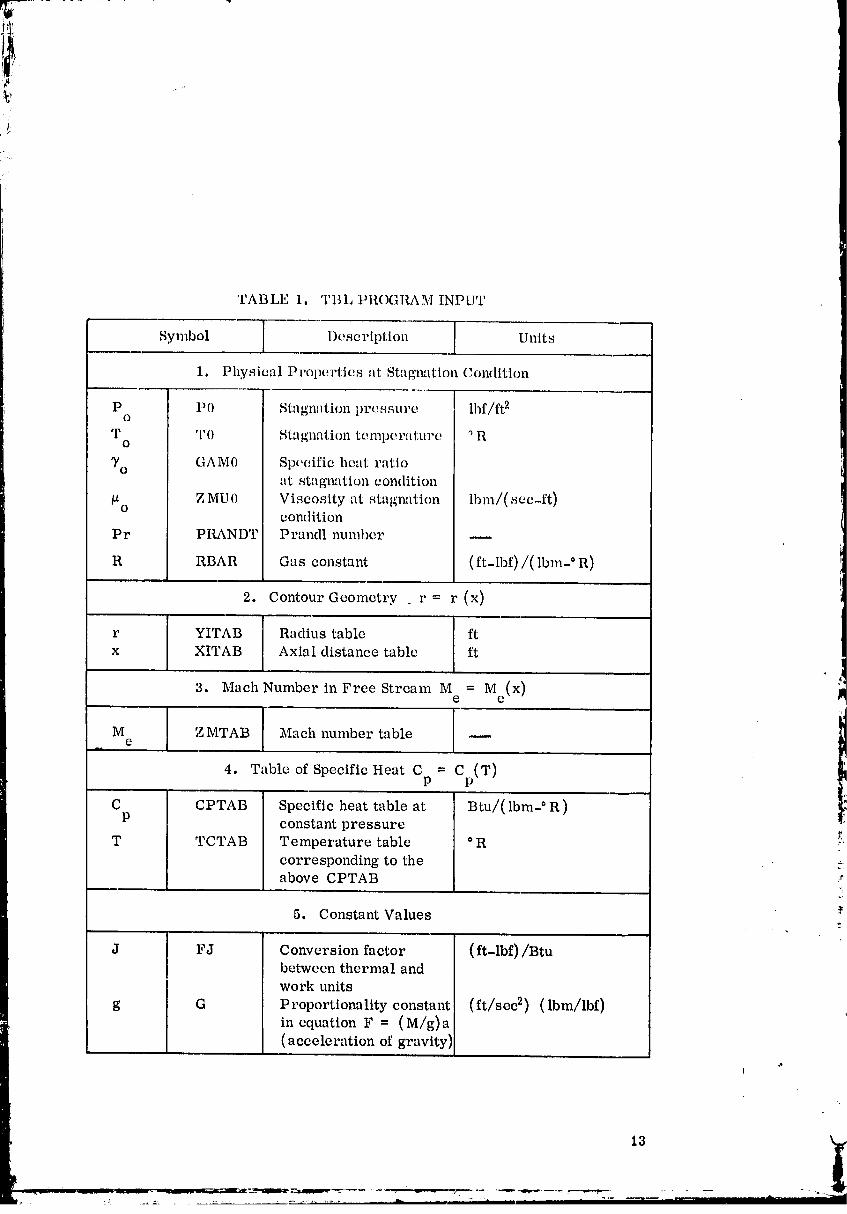
• ::.":!!.:.-.' ( Tables 1 and 2 describe the TBL computer program input variablesi': " .:::" and the results printed out by the program. Figure 2 shows the TBL computer .
...., program subroutine linkage. A description of the individual subroutines in the !f!'... : ::: computer program is given in the next section.
O0000001-TSCIO
, i I_
TABLE 1. TBL PROGRAM INPUT
Symbol Description Units
1. Physical Properties at Stagnation Condition
P P0 Stagn:ltion pressure ] lbf/ft 2o
T TO Stagnqtion temper,,d:uru ° Ro
T° GAM0 Specific heut ratioat stagnation condition
_o Z MU0 Viscosity at stqgmltion lbm/(scc-ft)condition
Pr PRANDT Prandl number --
a RBAR Gas constant (ft-lbf)/( lbm-° R)
2. Contour Geometry r = r (x)
r YITAB Radius table ft
x XITAB Axial distance table ft
3. Mach Number in Free Stream M = M (x) ]me e
M Z MTAB Mach number tablee
4. Table of Specific Heat Cp = Cp(,_T)
C CPTAB Specific heat table at Btu/( lbm-° R )P constant pressure
r,T TCTAB Temperature table ° R
corresponding to theabove CPTAB
5. Constant Values
J FJ Conversion factor (ft-lbf)/Btubetween thermal andwork units
g G Proportionality constant (ft/sec s) (lbm/lbf)in cquation F = (M/g) a(acceleration of gravity)
13
O0000001-TSC11
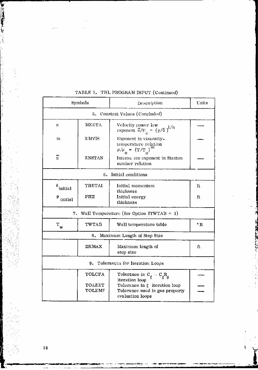
',i: TABLE 1. TBL PROGRAM INPUT (Continued)/
Symbols I)e seription Units
5. Constant Values (Concluded),m
n MZETA Velocity power law 1/n,, exponent _/U = (y/6)e
m Z MVIS Exponent in viscosity-temperature relation
i! /_/'_o = (T/To)mn ZNSTAN Interac Aon exponent in Stanton _
number relation
6. Initial conditions
" 0 THETAI Initial momentum ft: initial' thickness
"":::.-:::..: 9 initial PHII Initial energy ft• '. thickness•. : i'.
::....
• ..2Z . ...
'::!)i" ..:. 7.1 7. Wall Temperature (for Option ITWTAB = 1)
. . : .:._.... T TWTAB Wall temperature table ° RW• ." . -"
' - :'. 8. Maxinmm Length of Step Size• .: ._ ..:
• ". 4:... •
" );_.-;: DXMAX Maximum length of ft.... ?! ..
. ...._:: step size. ._. ": .
- - 9. Tolerancca for Iteration Loops
TOLCFA Tolerance in Cf .. CfR 0iteration loop
tTOLZET Tolerance in _ iteration loopTOLZMF Tolerance used in gas property
evaluation loops
• 14 i
00000001-TSC13
i_ _,
i: i:
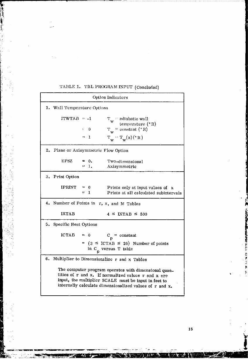
_ TABLE 1. TBL PROGRAM INPUT (Concluded)
Option Indicators
1. Wall Tcmpcrature Options
ITWTAB "-: -1 T :: adiabatic wall
w temperature (° R)
:: 0 T = constant (°R)W
• = 1 T :: W (x)(°R)W W
2. Plane or Axisymmetric Flow Option
" : EPSZ = 0. Two-dimensional
= 1. Axisymmetric
3. Print Option
:;'.i!: IPRINT = 0 Prints only at input values of x• -- = 1 Prints at all calculated subintervals
•.' "/..
!..,-iT " 4. Number of Points in r, x, and M Tables !!
:'."i .. ':: i."_'
. :.:"': 1XTAB 4 - IXTAB - 500 |lil
l
• ' ,.
.. 5. Specific Heat Options
""i.,. ICTAB = 0 C = constant.: p
: = (3 - ICTAB -< 20) Number of points _. in C versus T table _I'
P
6. Multiplier to Dimensionalize r and x Tables
The computer program operates with dimensional quan- .titles of r and x. If normalized values r and x are • r
input, the multiplier SCALE must be input in feet tointernally calculate dimensionalized values of r and x.
15
•". .
00000001-TSD01
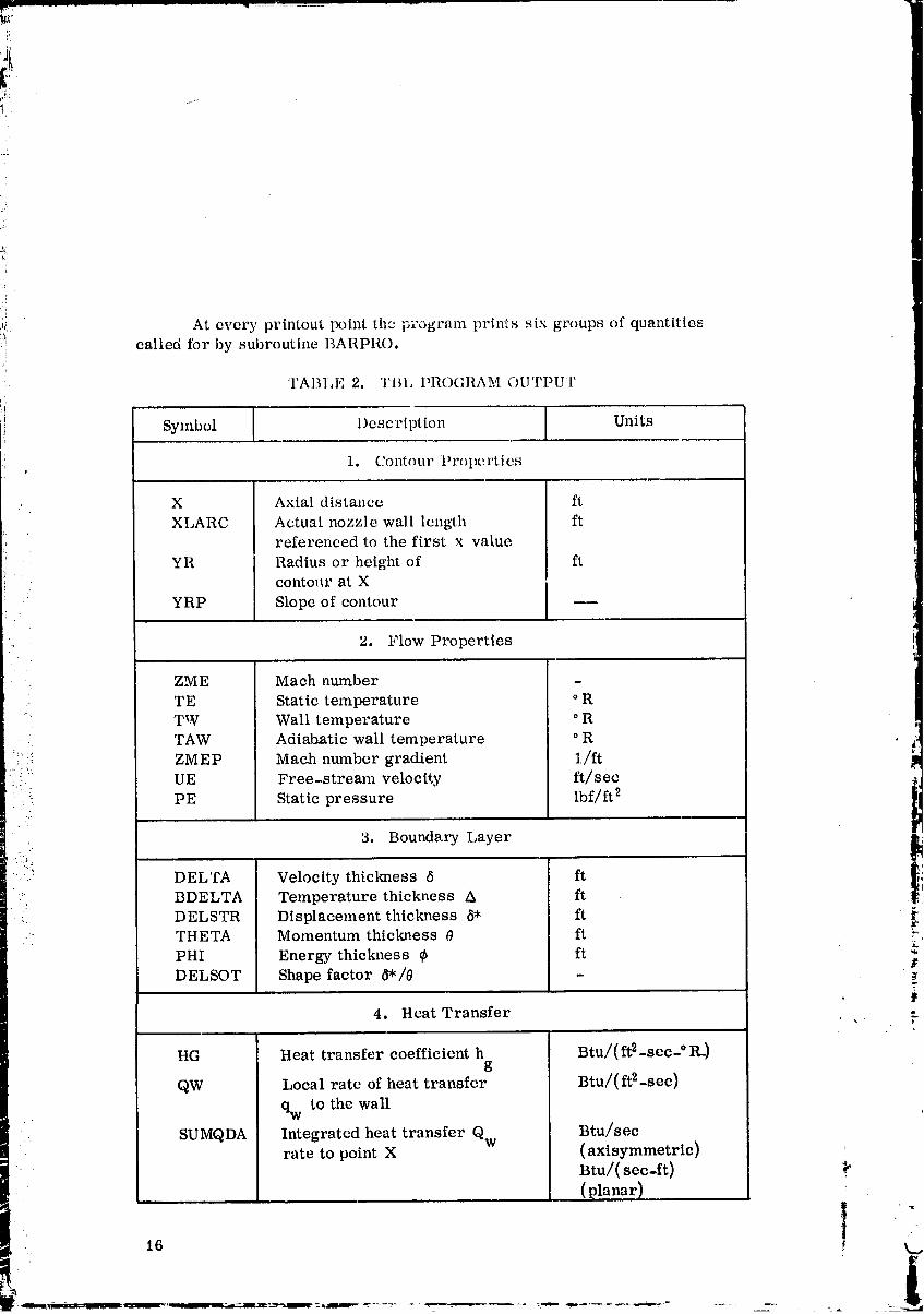
_!_ At every printout point the program prints six groups of quantities:_ called ibr by subroutine BARPRO.
! "lAl_l,l, ," 2. "l'l_lJ PROGRAM OUTPUT
Ii Symbol Description Units
1. Contour Pr()pertiesi
X Axial distance ft
XLARC Actual nozzle wall length ftreferenced to the first x value
YR Radius or height of ftcontollrat X
YRP Slopeof contour ----
2. Flow Properties
ZME Mach number
TE Static temperature ° R
: TW Wall temperature ° R m
TAW Adiabatic wall temperature ° R _,=:::: ZMEP Mach number gradient 1/ft, ..(!:.
UE Free-stream velocity ft/sec _jPE Static pressure lbf/ft 2
3. Boundary Layer
_ DELTA Velocity thickness 6 ft
:. BDELTA Temperature thickness A ft
_. DELSTR Displacement thickness b'* ft• " THETA Momentum thickness 0 ft r
PHI Energy thickness _b ftDELSOT Shape factor 6"/0 - ._
T
4. Heat Transfer ,
HG Heat transfer coefficient h Btu/(ft2-sec-'R -)g
QW Local rate of heat transfer Btu/(ft2-sec)
qw to the wall
SUMQDA Integrated heat transfer Qw Btu/secrate to point X (axisymmetrtc)
Btu/(scc-ft)
(Planar)|
• 16 ! k._
t
00000001-TSD02
' i
i_ _
],-
"i
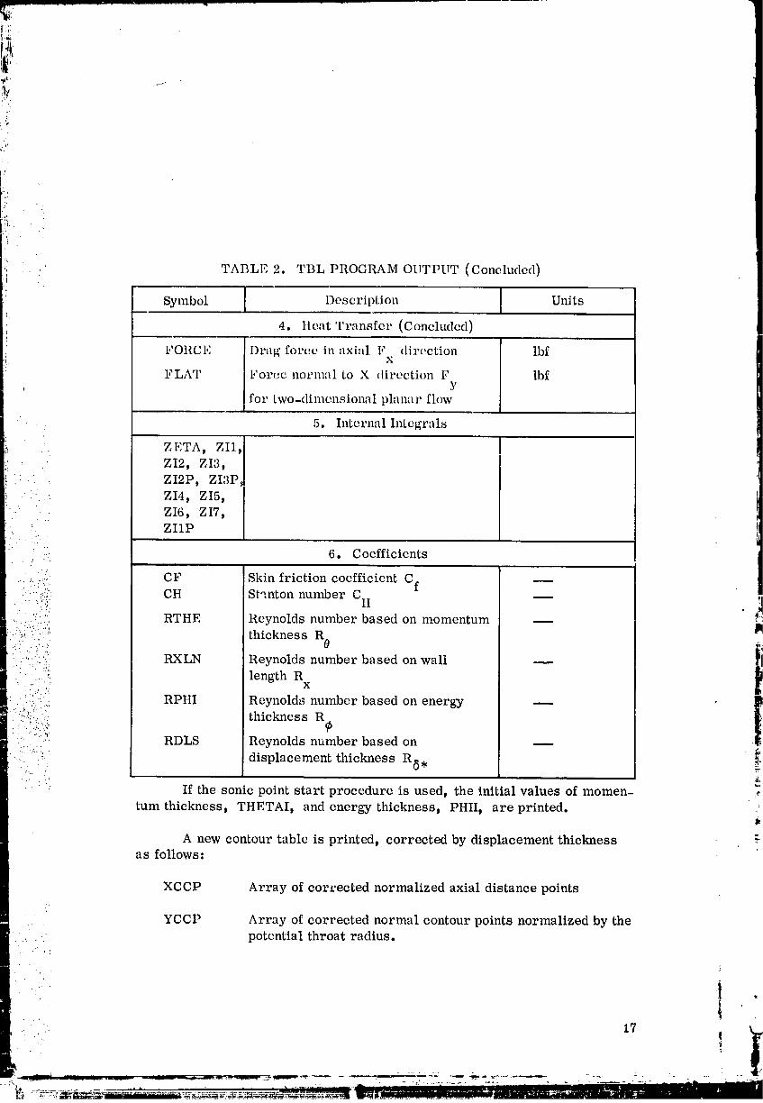
:i_: TABLE 2. TBL PROGRAM OUTPUT (Concluded)
..
Symbol Description Units
4. Heat Transfer (Concluded)
FORCE Drag force in axial F direction lbfX
FLAT For(.c normal to X direction F lbf,: Y
for two-dimensional planar flow
5. Internal Integrals
ZETA, ZII_
ZI2t ZI3," ZI2P_ ZI3P.
.. ZI4, ZI5,ZI6, ZI7,
" ZIIP
i'. " "
_ 6. Coefficients
......;,,:.:,. CF Skin friction coefficient Cf --., -' - .:.
• :,:::_ CH St",nton number C H __., :..(_,:
'"...... RTHE Reynolds number based on momentum -- _"::.:. _.. .
i-..:)_,i:::::i::'!;' thickness R0 lm
....."' RXLN Reynolds number based on wall --" -"_':_: length R•! ; .:.i.".i., x
i.:i:,_::.";: RPHI Reynolds number based on energy _ _,
: )..:i:i.!_:..::_.. thickness R_ t:':: ": .;Y, RDLS Reynolds number based on --.,. ..
' !:i'_':_ displacement thickness RS..'...
If the somc point start procedure is used, the initial values of momen- ._
rum thickness_ THETAI, and energy thickness_ PHII_ are printed.
A new contour table is printed, corrected by displacement thicknessa s follows:
XCCP Array of corrected normalized axial distance points
YCCP Array of corrected normal contour points normalized by thepotential throat radius.
1
x
00000001-TSD03
^
7_
:!
:i
i:.i . ".' •
18
00000001-TSD04
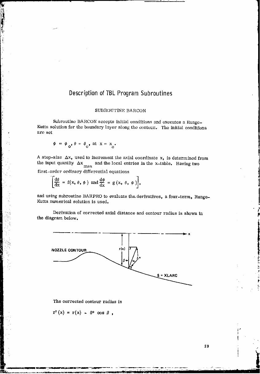
Descriptionof TBLProgramSubroutines
SUBROUTINE BARCON
Subroutine BARCON accepts initial conditions and executes a Runge-Kutta solution for the boundary layer along the contour.• The initial conditions
,, arc set
= ¢o, 0 = 0o, at x = x .O
A step-size Ax, used to increment the axial coordinate x, is determined from
the input quantity Ax and the local entries in the x-table. Having twomax
first-order ordinary differential equations
de-- = f(x, 0, 9) and_x = g(x, O, ¢ ,
.. and using subroutine BARPRO to evaluate tha derivatives, a four-term, Runge-• Kutta numerical solution is used,
? !:i Derivation of corrected axial distance and contour radius is shown in l!i. .. the diagram below,
•.."
' _ l
" -L.
_.. -":,,
" i:.!:i. NOZZLECONTOUR rlx)
The corrected contour radius is
r' (x) = rCx) - _* cos _ ,
?
19
00000001--I-SD05
, and
_= +
Thus, one obtains
8*r t _x_= r tx_ -d _
YCCP.
• ,, ,, j: l+1;. :: .. :,
'f.
The corrected axial distance is
-'... :'_....:..,/
-:, x' = x+ 8" sin _, =:-:... .. -,.:,
.: :' " where•., -.,...
' : ":" dr dr/dx dr/dx" sin fl = ds ds/dx "
• ", " .. D
': : : 1 +I: ? :.ii:..
:::eL.::• ,:: .;
: :: .... Thus, one obtains g.
6* drx t = x + -..- XCCP.
J1+T
COMMON BLOCKS
COMMON blocks INPUT t INTER, LOOKUP, OUTPUT, and TABLESare used.
- . , .
00000001-TSD06
TBL SUBROUTINES
SubroutineDIRECT callsBARCON.
BARCON callssubroutinesBARPRO, QUITS, START, ANt) XNTERP.
FORTRAN SYSTEM ROUTINES
r
FORTRAN libraryroutinesA LOG and SQRT are used.
Built-in FORTRAN library routine ABS is used.
CALLING SEQUENCE
i _.: i.ii _i':i The subroutine calling sequence is:..j.
•" :. _ :: CALL BARCON
SOLUTION METHOD
:ii':::-;....,_. ::.. Compute the cubic root of the Prandtl number.
• .... ),3: ........ ::" 1. PRE103 = (PRANDT
: !::!!:ili!!iiill! ii!.:ii:!iii'::ii::i ::i Compute term in denominator of the Stanton number, i
2. CHPAR1 = 1.0 - PRANDT + Ln ((6.0)/((5.0)(PRANDT) + 1.0))
:" " 3. MZETAM = MZETA - 1• _. "'::_..... _,::, Save the value of exponent in velocity profile. _.
• ... :'. : ....
."- . " .. _'. ..
"" " " "" 4. ZMZETA = MZETA _"
5. ZMZETP-- ZMZETA + 1.0f
6. ZMZETM = ZMETA - 1.0 _'
7. RMZETA = (1.0)/(ZMZETP)
8. OOMZET = (1.0)/(ZMZETA)
. .: ._ .. . -.
• 21 i• . ... ,.
00000001-TSD07

):
Set the initial value of axial distance.
9. X = XITAB(1)
Set the initial value of the difference of axiM distances.
i0. DX = O.0
r
Set the initial integrated heat transfer rate.
12. SUMQDA = 0.0
... Set the initial drag force.
:: 13. FORCE = 0.0
•: Set the initial normal force.
• " " 14. FLAT = 0.0
' i';_!i Set the initial local heat transfer rate.
i::_:_.!:, 15..QW = 0.0
:;:::::!i::! Set the initial heat transfer coefficient.
1
....
• ;..' 16. HG = 0.0.:... t.. -.... *
m _ ::::::!:;i/::_: Set the following parameters.
. :i: 17. IXPOS = 1
.... 18. IMX = 0 .,
19. ITX=0
20. IPX = 0
00000001-TSD08
23. DXRII() =- 0.0
24. I1 LG = 2
Initial assurr_ption of adiabatic sldn fricLion coefficient.
" Set the initial value of the sordc point start indicator.
26. ISTART = 0
Check whether the sonic point start procedure is to be us'_,d.
27. IfTttETAI -< 0,0, go to 30
IfTtIETAI > 0.0, go to 28
Calculate the shape factor [ based upon initial assumptions.
"- :i_:. 28. ZETA = ((PHII)/(THETAI))RMZETA. ._.,.
_::::i:1".'-, 29. Go to 32 ,_,• .- ..
::: .:., , Use the sonic point start procedure.
1
: 30. CALL START• : " L' [:.
•: :,), .- .
: :';:i!':.,_ Set the sonic point start indicator.:- .:..-_:, "_:
.-.. 'l:
_ :/ .... 31. ISTART = 1
•" "" 32. CFAGP = CFAGT¢
Set the energy thickness equal to the input value. ,_
33. PHI = PHII
Set the momentum thiclmess to the input value.
34. TttETA = THETAI
•' i
23
• .- ." •
-_-_" _-- - _ - . . _ _. . _ -- - __ . _ -.
00000001-TSD09
35. XIIIAHI,', XYrAI_(I)
Set I,lm lli,<-il;vMu(' cff :_xi:_l di,-d.:iiu:_, Ix) Lira ]a<-Itwllll_' iri lh_; :iXilll. diHl.:i.n(>,(;
I;Iil11 i_,
': :Ill. XH,Ni) :-: X.ITAI{ (IXTAII)
,hock whether the, iVl.ach nuilll)c:r t:t/llo {,_mtaJns al. loa.sl, two wl.luos.
37. I17iX'I'AI>_ =; l, go to 39
: ffLXTAFt > 1_ go to 38
•: 38. DXRItO = (XITAB(2) - XmASE)/(10.0)
" )-.". Call subroutine BARPRO to obtain C h, Cf, d0/dx, d_/dx, qw' hg,
";.[_"-;::_"..... FORCE, SUMQDA, XLARC, _nxidso on...:.;!:.-.
:" :.i.. .. ..... 39. CALL BARPRO(1):...:...,.: .,-. il
':::; .i :_:...." Call subroutine BARPRO to print the output of BARPRO.7 :'::,i;' " " •" : ": 't
•.. .... .... 40. CALL BARPRO(5)
;.):[:i_];;:)>...._,•. Call subroutine XNTERP to obtain the radius YR and its first derivativeYRP.
:" i"'""_:[i:.-' 41. CALL XNTERP iX, YR, YRP, IYX, XITAB, YITAB, IXTAB,•CYX, I1VIX) _.
t
Save initial displacement thielmess and radius of the contour.
42. DEL -- DELSTR _-
. .' . '..
24 i "
"_i'i_'!l_-'lIl=_" " _ "_-"':_ =---'_ ":"....... _ . . _. -_' _'.. - '_ _ . --:- _ Z :;;---: " •-2"!' " -_:-
O0000001-TSDIO
4d. ONOC .- SQRT (1.0 + (YRP)(YRP))
Compute the first eorrecto.d axinl distance point and contour v)int.
,J,_.xcc_,(1) .- x. (,)_,:_,s'l'[t)(vm')/(ONOC)
,: ,J(;. vc('p(1) _ vl_ _ (DE_,S'.nO/(_)Noe)
. • Check whettlor the roach number table contains at least two valueso
55. ZNX = NX
': I;0. PIl!()I_l) :-PtII
61 . 'l.'IlI,Ol,l) '.PIIETA
Save the value o£ the _xial distance.
62, XOLD = X
_a. DPnmK(1)= (DX)(PItrP):
• • . ...,
. .:. 64. DTItERK(1) = (DX)(THETAP)
..... ... ,, Compute new value of axial distance.• ....,.
• . v ,
=' .... 65. X = XOLD + DXO2.:,... ., .. ,...;.... .. ,..
:";..... ' ;36. Do 80, IRK = 2,4i:%. i
• <,: Check for last time through the Do-loop.
' I
;..v.. :._i j .:: : : ".'_
}.::_'.ill (: ..= 67. If iRK _ 4, go to 74•....;:...,..:.
::- 2! " .• KIRK= 4, go to 68
Compute new value of axial distance. -' f
68. X = XOLD + DX
69. If I (X - XNEW)/(XMAG)! > I..0E-6, goto71 "
If ] (X -XNEW_/(,XMAG)I _ 1.0E-6, go toT0
70. X = ?;:NEW
• .-..
'• " • ' t
26
_. _. _. ...... : . _ __. i ..... .'_ 2_ 2_--: _:. _'7-:--:_---
0000000"I-TSD'I 3
,: Compute new value of energy thickness and momentun_ thickness.
71. PHI = PHIOLD + DPHmK(mK - 1)
72. THETA = THEOLD + DTHERK(mK - 1)
73. Go to 76
i
Compute energy thickness and momentum thielmess.
74. PHI -- PHIOLD + (DPHIRK(IRK -))(0.50)
75. THETA -- THEOLD + (DTHERK(IRK -1))(0.50)
: Check whether the energy thickness is negative or zero.. ".L '::.
; ':i :! 76. If PHI -- 0.0, go to 85
4".
• If PHI > 0.0, go to 77
::.:. • Cheek whether the momentum thickness is negative or zero.
:_: .: :: : 77. IfTHETA -< 0.0, go to 85 P
"' : . If THETA > 0.0, go to 78
1
? :! .. Call subroutine BARPRO to obtain d_b/dx and d0/dx.
!i:): : 78. CALL BARPRO(IRK)
.-... .._ : ::': 79. DPHmK(IRK)= (DX)(PH/2) _
! 80. DTHERK(IRK) = (DX)(THETAP)
Compute energy thickness and momentum thickness according to the
Runge-Kutta -G ill method.
81. PHI = PHIOLD + (DPHIRK(1) + (2.0)(DPHIRK(2))
+ (2.0)(DPHIRK(3))+ DPHIRK(4))/(6.0)
• . ! ..
00000001-TSF01
•;i
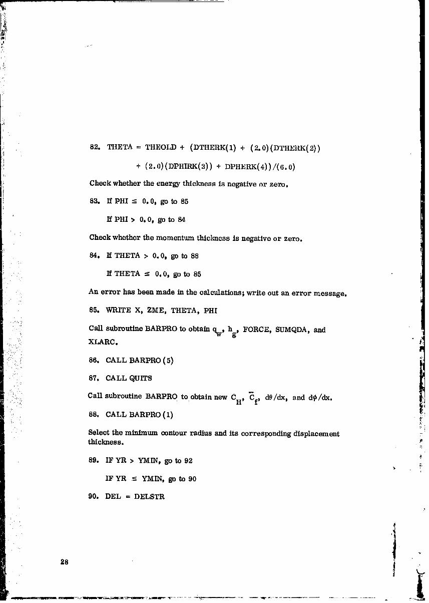
,,: 82. THETA = THEOLD + (DTHERK(1) + (2.0)(DTHERK(2))
i:: + (2.0) (DPHIRK(3)) + DPHERK(4) )/(6.0)
Check whether the energy thickness is negative or zero.
83. If PHI < 0.0, go to 85
IfPHI > 0o0, go to 84
Check whether themomentum thlclmcssis negativeor zero.
84. IfTHETA > 0.0t go to 88
An error has been made in the calculations; write out an error message.
85° WRITE Xt ZMEI THETA, PHI
: P
86. CALL BARPRO (5)
87. CALL QUITSCaLl subroutine BARPRO to obtain new CH, _f, d0/dx, and d_/dx.
• 88. CALL BARPRO (1) _:
...•
Select the minimum contour radius and its corresponding displacementthiclmess.
89. IF YR > YMIN, go to 92
IFYR <- YMIN, go to 90
90. DEL = DELSTR
00000001-TSF02
! p.'
t
I.i:!
_ii_
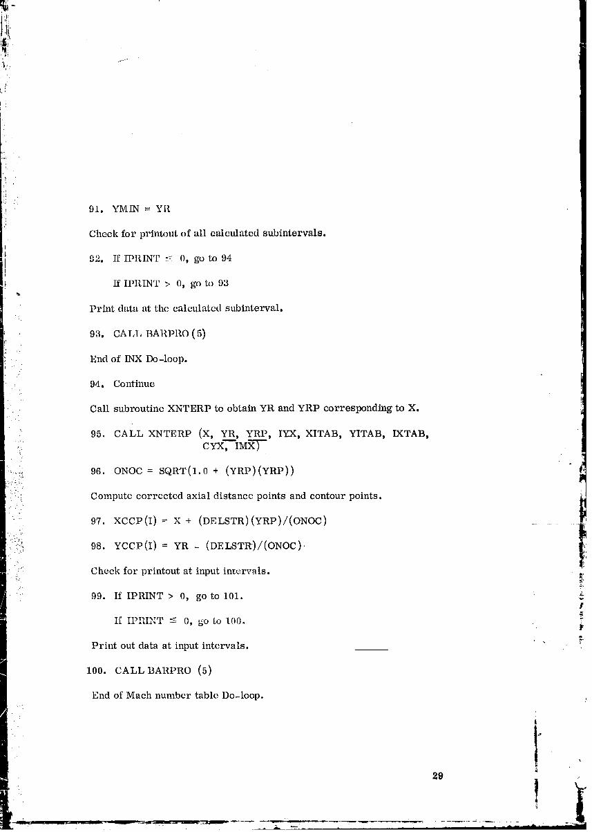
91. YMIN = YR
Cheek for printout of all calculated subintervals.
i92. If IPRIN'r _ 0, go to 94
If IPRINT > 0, go to 93
Print data at the calculated subinterval.
93. CAt,T, BARPRO (5)
End of INX Do-loop.:
94. Continue
Call subroutine XNTERP to obtain YR and YRP corresponding to X.
95. CALL XNTERP (X, YR, YRP, IYX, XITAB, YITAB, IXTAB,
cY'X__tMX---y-
':
,,... 96. ONOC = SQRT(1.0 + (YRP)(YRP))-...'." •
, :': ': Compute corrected axial distance points and contour points. _,_. " !',
i
" 97. XCCP(I)= X + (DELSTR)(YRP)/(ONOC) ........
.. _'_
•: _.:,:'.. 98. YCCP(I)= YR- (DELSTR)/(ONOC).
.... Check for printout at input intervals. _:
99. If IPRINT > 0, go to 101. ,_f
If IPRINT _ 0, go to 100, i_
Print out data at input intervals. _"
100.CALLBARPRO(5)
End of Mach number table Do-loop. )
29
1
00000001-TSF03
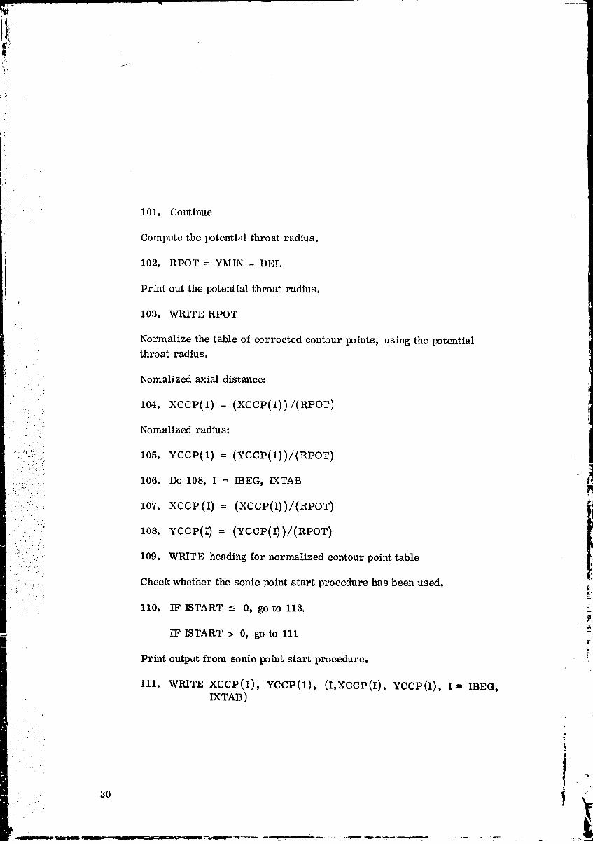
101. Continue
Compute the potential throat radius.
102. RPOT = YMIN - DEL
Print out the potential throat radius.
103. WRITE RPOT
Normalize the table of corrected contour points, using the potentialthroat radius.
Nomalized axial distance:
104. xccP(1) = (xccp(1))/(aPOr)
• _: Nomalized radius:• - . ...
_'/':i:_ 105. YCCP(1) = (YCCP(1))/(RPOT)
' '" .... 106. DO 108, I = IBEG, IXTAB
!':::::i.:!..:.:":._ lO7, xcep (I) = (XCCP(I))/(RPOT) '_
1
: ;. : 108. YCCP(I) = (YCCP(I))/(RPOT)
:':i:,.:; 109. WRITE heading for normalized contour point table
Check whether the sonic point start procedure has been used.• ....:
: 110. IF _TART <- 0, go to 113,
IFISTART > 0, go to 111f
Print output from sonic poh, t start procedure.
111. WRITE XCCP(1), YCCP(1), (I,XCCP(I), YCCP(I), I = IBEG,IXTAB)
?
-. . !
" "" i
. t
00000001-TSF04
iii
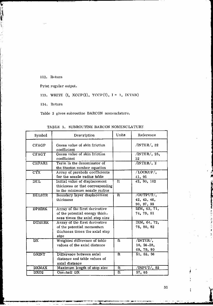
'_.i 112. Return
Print regular output.
113. WRITE (I, XCCP(I), YCCP(I), I= 1, IXTAB)
114. Return
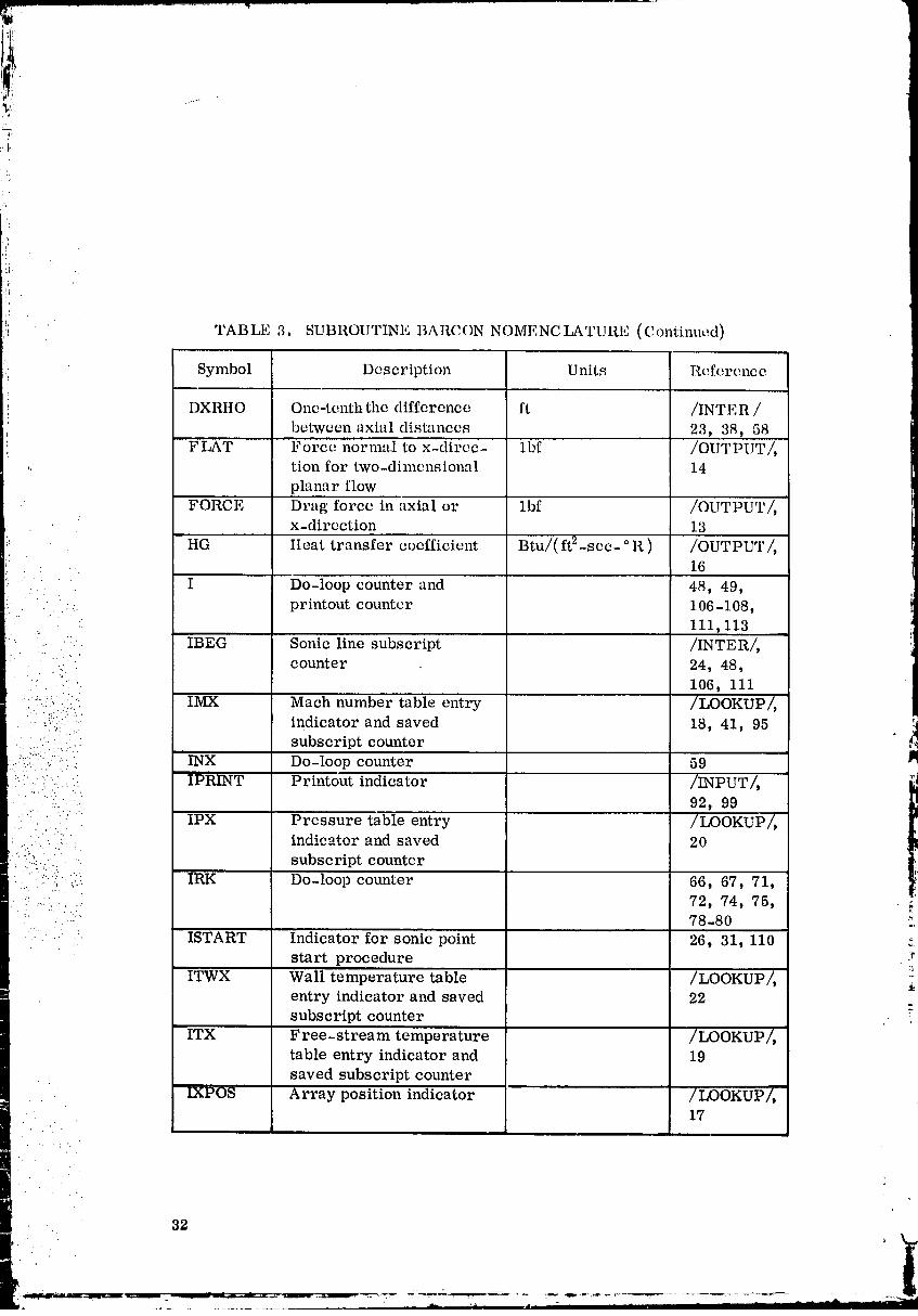
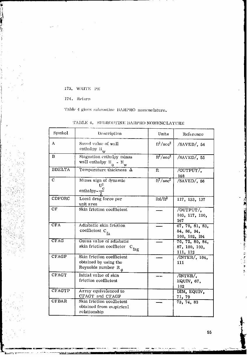
Table 3 gives subroutine BARCON nomenclature.
TABLE 3. SUBROUTINE BARCON NOMENCLATURE
Symbol Description Units Reference
CFAGP Guess value of skin friction /INTER/, 32coefficient
: CFAGT Guess value of skin friction /INTER/, 25,coefficient 32
CHPAR1 Term in the denominator of /INTER/, 2
the Stanton number equationi
- CYX Array of parabola coefficients /LOOKUP,/,for the nozzle radius table 41, 95
DEL Initial value of displacement ft 42, 90, 102
thickness or that correspondingto the minimum nozzle radius
:: DELSTR Boundary layer displacement ft /OUTPUT/,thickness 42, 45, 46,
90, 97, 98
DPHIRK Array of the first derivative DIM, 63, 71,of the potential energy thick- 74, 79, 81 ,:_
ness times the axial step size
DTHERK Array of the first derivative DIM, 64, 72, :_of the potential momentum 75, 80, 82 :_thickness times the axial stepsize
DX Weighted difference of table ft /INTER/,values of the axial distance 10, 56-58,
68, 79, 80
DXINT Difference between axial ft 51, 52, 56distance and table values of
axial distance
DXMAX Maximum length of step sizc ft /INPUT/_ 52 ._DXO2 One-half DX ft 57, 65 J
31 , k.,L
..! TABLE 3. SUBROUTINE BARCON NOMENCLATURE (Continued)
Symbol Description Units Reference!.
DXRHO One-tenth the difference ft /INTER /
between axial distances 23, 38, 58FLAT Force normal to x-direc- lbf /OUTPUT/,
,. tion for two-dimensional 14
planar flow
FORCE Drag force in axial or lbf /OUTPUT/,x-direction 13
HG Heat transfer coefficient Btu/( ft2-sec- ° R ) /OUTPUT/,16
" I Do-loop counter and 48, 49,
:.: printout counter 106-108,111,113
IBEG Sonic line subscript /INTER/,
: '...: counter 24, 48,• .-'. 106, iii
..//-..:.. IMX Math number table entry /LOOKUP/,•'.% . ... :.,z-._,.
- -:::: :- indicator and saved 18, 41, 95
,:...i.' :: subscript counter.._..... " .. INX Do-loop counter 59 l_
........ IPRINT Printout indicator /INPUT/,• "'" ' :: 92, 99
•: " ._-i:: IPX Pressure table entry /LOOKUP/,' :" indicator and saved 20
! : ..:-:::i:.il : subscript counter•:!". i IRK Do-loop counter 66, 67, 71,::. ., %
m .... ".... ::. : .. 72, 74, 75,• :: :::: 78-80
..:. . . ...
• ..- • ISTART Indicator for sonic point 26, 31, 110start procedure r
ITWX Wall temperature table /LOOKUP/, ,entry indicator and saved 22subscript counter
ITX Free-stream temperature /LOOKUP/,table entry indicator and 1.9saved subscript counter
IXPOS Array position indicator /LOOKUP/,17
- 32
00000001-TSF06
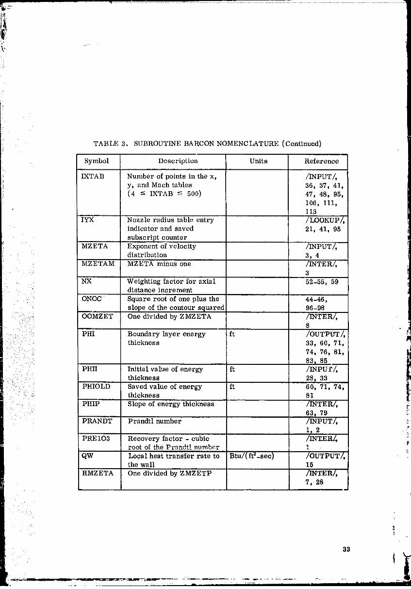
[ '
TABLE 3. SUBROUTINE BARCON NOMENCLATURE (Continued)
Symbol Description Units Reference
IXTAB Number of points in the x, /INPUT/,
y, and Mach tables 36, 37, 41,(4 -< IXTAB -< 500) 47, 48t 95,
106, 111,'; 113
IYX Nozzle radius table entry /LOOKUP/,indicator and saved 21, 41, 95
subscript counter
MZETA Exponent of velocity /INPUT/,• • distribution 3, 4
• MZETAM MZETA minus one /INTER/,
.. NX Weighting factor for axial 52-55, 59:.. distance increment
.. ONOC Square root of one plus the 44-46,
slope of the contour squared 96-98
•. -.:.:....-._: OOMZET One divided by ZMZETA /INTER/,- -'. .. 8
•:...::: .........'. PHI Boundary layer energy ft /OUTPUT/,. ._._ : :..: thickness 33, 60, 71,
• . :../i"":: 74, 76, 81,83_ 85
._ . PHII Initial value of energy ft /INPUT/,.... ...... : thickness 28, 33
• • _ j i
-.":"i::-... PHIOLD Saved value of energy ft 60, 71, 74,.:. ":!:_ ._ thickness 81
: ' PHIP Slope of energy thickness /INTER/, _:_'.. .":::. 63, 79 '
PRANDT Prandtl number /INPUT/, _-
1, 2 ._'_
PRE 103 Recovery factor - cubic /INT_ER_root of the Pr_ndt! number 1
QW Local heat transfer rate to Btu/(ft"-see) /OUTPUT/,the wall 15
RMZETA One divided by ZMZETP /INTER/,7, 28
33
00000001-TSF07
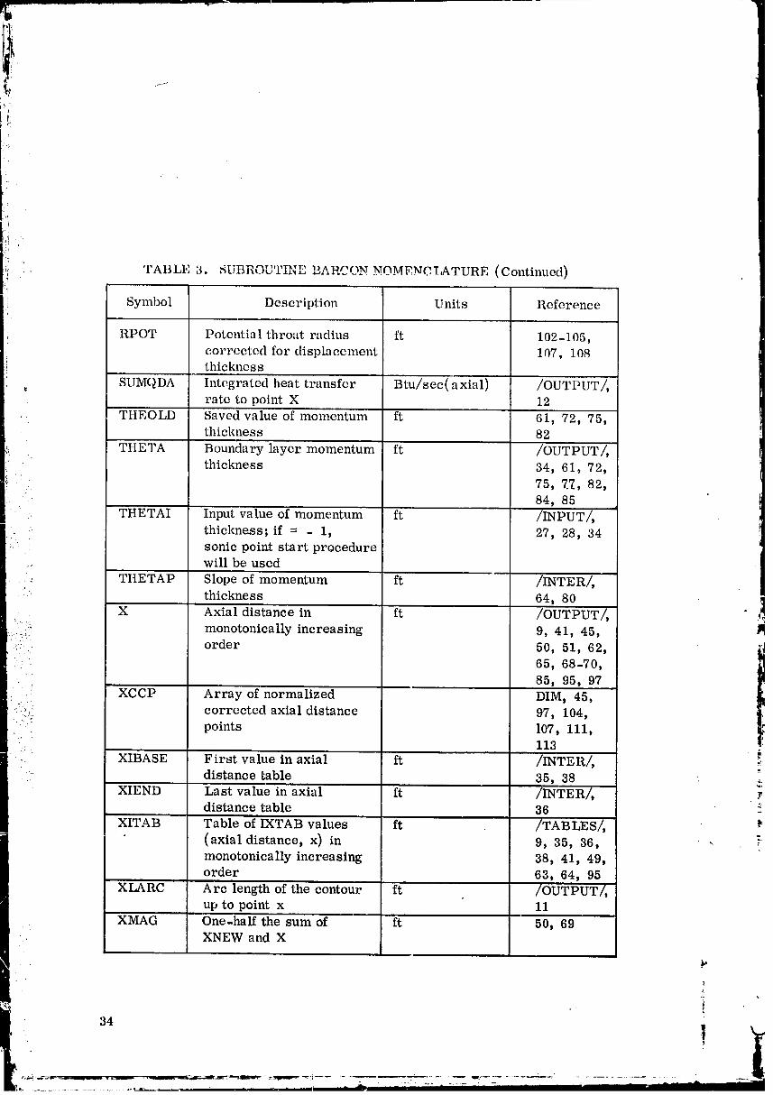
'j
Iii ' TAB TJtt_ 3, _Ur_ "n__n__P_"......... _'_..'_,T ...... _TUI_E (Continued)"
Symbol Description Units Referonce
RPOT Potentia 1 throat radius ft 102-105,corrected for displacement 107, 108thickne s s
,.. SUMQDA Integrated heat transfer Btu/sec(axial) /OUTPUT/,rate to point X 12
TtIEOLD Saved value of momentum ft 61, 72, 75,thickness 82
THETA Boundary layer momentum ft /OUTPUT/,thickness 34, 61, 72,
75, 7._, 82,• 84, 85
THETAI Input value of momentum ft /INPUT/,.. thickness; if = - 1, 27, 28, 34
sonic point start procedure... will be used
•-_ THETAP Slope of momentum ft /INTER/,
thickness 64, 80
X Axial distance in ft /OUTPUT/, _../;:_ monotonically increasing 9, 41, 45,
....: order 50, 51, 62, ,_'_
' 65, 68-70,• _ 85, 95, 97
XCCP Array of normalized DIM, 45,::.-_. corrected axial distance 97, 104,
.. :i points 107, 111,• 113
_. " XIBASE First value in axial ft /INTER/, il
:? distance table 35, 38 _.XIEND Last value in axial ft /INTER/,
distance table 36 T
XITAB Table of IXTAB values ft /TABLES/,(axial distance, x) in 9, 35, 36, -
monotonically increasing 38, 41, 49,order 63, 64, 95
XLARC Arc length of the contour ft /OUTPUT/,up to point x 11
XMAG One-half the sum of ft 50, 69: XNEW and X
34
b. " !
00000001-TSF08

TABLE 3. SUBROUTINE BARCON NOMENCLATURE (Concluded)
Symbol Description Units Reference
, XNEW Successive values of axial ft 49-51, 69, 70distance from the XITAB
table
,, XOLD Saved value of axial ft 62, 65, 68distance
YCCP Array of corrected DIM, 46, 98,
contour points normalized 105, 108,by the poLential throat 111, 113radius
YITAB Nozzle contour radius ft /TABLES/,table related to IXTAB 41, 95array
! YMIN Saved value of initial or ft 43, 89, 91,minimum radius or height 102
-. of contour
YR Nozzle radius or contour ft /OUTPUT/,"" height 41, 43, 46,
89, 91, 95,'" :'" 98 _i
:.:." YRP Slope of contour 41, 44, 45,: ' 95-97
• Z ETA Shape factor /OUTPUT/,28
- ,_ Z ME Mach number /OUTPUT/,.'..q
85
.... ZMZETA Real value of MZETA /INTER/,
_. 4-6, 8ZMZETM ZMZETA minus one /INTER/, 6 _
ZMZETP ZMZETA plus one /INTER/, 5, a7 "_
ZNX Real value of NX 55,. 56
35
O000000]-TSF09

SUBROUTINE BARPRO
Subroutine BARPRO calculates the boundary layer parameters from
initial or previously determined energy Lhickness _, momentum thickness O,
and _d0 and d_dxalong the contour at a point x.
The interpolation routine XNTi-_RP is used to evaluate inviscid flow anddM dT
e e
contour properties and derivatives at point _', such as Me, .-_, T e, -.-_, r,dr
and _. Then subroutine ZETAIT is called and the shape factor _ and bound-
ary layer thicknesses A, 6, and 6 * are computed. An iteration procedure is
used to calculate the skin friction coefficient Cf and the Stanton number C H.This procedure is as follows:
1. An initial guess Cfag is made.
2. The term C_ = __w is calculated.e
::::_: 3. Subroutine CFEVAL is used to evaluate Cf as a function of CfR_-.:.: .:
= - - are _alculated.
: 4. Theterms andCfa ___/ (TTS) m::: \ awl ( e/ \ aw.t.
': 5. A relative error comparison is made. If
Cfa - Cfag -< TOLCFA,
Cfag
convergence is satisfactory. Otherwise a form of Wegstein ' s method is used
to calculate a new guess Cfa; and steps 2 through 5 are repeated up to amaximum of 50 iterations.
36
O0000001-TSFIO
-7
9:
'i.
!b
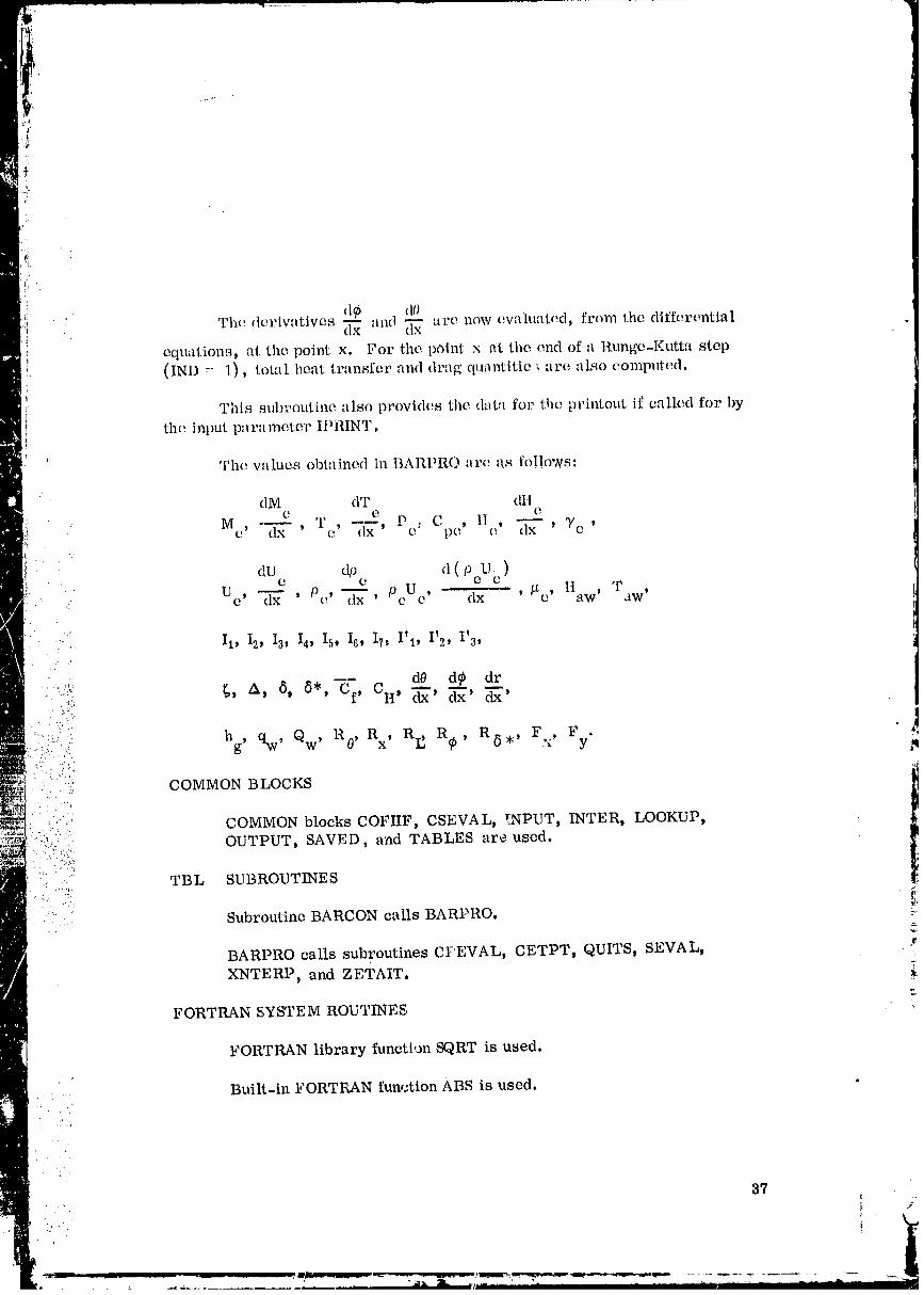
d@ d0The d<:rivatives d-_x and _ at<, now evaluated, from the differential
equation,_, at the point x. For the point x at the end of a l_.unge-Kutta step
(IND __ 1), total heat transfer and drag q_uantitie ' are also computed. (
This subroutine also provides the d;_t:_ for the printout if called for bythe input parameter II)RINT.
i:
The values obtained in BARPRO are {Is follows"
dM dT (LIie e e
Me , -_ T , ---- Pc: Cpe' H _ 7e ,dx ' e dx ) e ' dx '
dUe dpe d ( pcUc )Uc' c--_ ' Pc' c_x' PeUo ' dx ' /'to' Haw) Taw' i
T'i
:. .. II, 12, 13) Io Is) 18) 17,I' I, I' 2, I'3)
.::,...,.>,> %,..,,
.....::_._'.:. hg, qw' Qw' R0' R , RI] R@ R ,, F , F • (
: ;'"::;:._ COMMON BLOCKS
! ../:..:._... COMMON blocks COFIIF, CSEVAL, _NPUT) INTER, LOOKUP)":"." ', OUTPUT) SAVED, and TABLES are used.
:{....,:_ TBL SUBROUTINES t? .-7...:.
.. Subroutine BARCON calls BARPRO. "
BARPRO calls subroutines CI:'EVAL) CETPT, QUITS, SEVAL, ._L
XNTERP, and ZETAIT.
FORTRAN SYSTEM ROUTINES
FORTRAN library function SQRT is used.
Built-in FORTF_N function ABS is used.
.'.' .
87f _
} >
00000001-TSF11
fl!!", CA LI,ING SLQU1,NCI%
The subroutine calling sequence is;
CALLBAr m O (IND)
! where,
, IND = program loop control indicator.
SOLUTION METHOD
Determine which program option is desired.
1. if IND = 1, go to2
If IND = 2, go to2
If IND = 3, go to 58
If IND = 4, go to2
: If IND = 5, go to 150
• Call subroutine XNTERP to obtain the free-stream Mach number Me
and its gradient dM /dx for a given x.e
..- 2. CALL XNTERP (X, ZME__._._,ZMEP,. IMX, XITAB, ZMTAB, _,.
:_ IXTAB, CMX, IXPOS) _
:" Save IMX.
3. IXPOS = IMX
Call subroutine XNTERP to obtain the free-stream temperature
T and its gradient dT /dx. =e e
4. CALL-XNTERP (X t TE t TEPD ITXt XITABt TITABp IXTAB,C TX7 LXff6"S)
i
38 k..
!
O0000001-TSF13

_: - Call subroutine GETPT to obtain the free-stream pressure P byeusing M and T .
e e
5. CALL GETPT (ZME, PE, TE)
Call subroutine SEVAL to obtain the speeific heat C and enthalpype
H by using T •e e
' 6. CALLSEVAL(1, CP_/E,U__E)
dH dT e
Determine the enthalpy gradient = Cpe _ x gJ .
7. HEP = (FJG)(CPE) (TEP)
'::. Compute the specific heat ratio /Te = Cp ecpe_ R/J / "
:' 8. GAME = (CPE)/(CPE - ROJ)
:..!_":. Obtain9.UE202thedynamic=H0 - HEenthalpy (U2e/2) . iThe free-stream velocity U is obtained from equation (9).' e
' " _ l
....... i0. UE = SQRT ((2.)(UE202))
e _,
- - dx "Determine the velocity gradient \ _xx U e ..
x_z.
II. UEP=-(HEP)/(UE) l_
= e
Obtain the free-stream density Pe Pe _ "
12. RHOE = (PE)/(TE)/(RBAR)
39
00000001-TSG01
i"% ¸
-i
I
3_
:i 13. it DXRHO ¢ 0.0, go to 16
IfDXRHO = 0.0, go to 14
i/ Save the initialdensitygradient.
tJ 14. RIIOEP = 0.0
15. Go to 32
16. IfX > XIBASE, go to 20
IfX - XIBASE t go to 17
Save the density p .e
17. Zl = RHOE
Put one as:
18. Z3 = 1.0
19. Go to 24
: Call subroutine XNTERP to determine M = (ERASE1)e
and dM /dx = (ERASE2) for (X-DXRHO).e
:2 20. CALL XNTERP (X-DXRHO, ERASE1, ERASE2, IMX, XITAB,• ZMTAB, IXTAB, CMX, IXPOS) "
.j:
: Call subroutine GETPT to obtain P = (Z4) and T = (Z5) _'e e
/.
corresponding to M = (ERASE1). :re .=.
21. CALL GETPT (ERASEI, Z.4.,Z_.55)
Compute the density Pe corresponding to Me. Pc =
22. Z1 = (Z4)/(Z5)/(RBAR)
4O
i
00000001-TSG02
Ii
*: Set point one as:i
:i 23. Z3 = 0.5i
i 24. If X < XIEND, go to 28
If X >- XIEND, go to 25
Set
25. Z2 = RHOE
:! 26. Z3 = 1.0
27. Go to 31
" Call subroutine XNTERP to obtain M = (ERASE1) and. .: e
dM /dx = (ERASE2) corresponding to X + DXRHO.e
;' 28. CALL XNTERP (X + DXRHO, ERASE1) ERASE2, IMX, XITAB,ZMTAB, IXT_AB, CMX, IXPOS)
-. CaD subroutineGETPT to obtainP = (Z4) and T = (Z5) ,_: e e .._
using the above M = (ERASE1).
1
e
29. CALL GETPT (ERASE1, Z4, Z5)
= (Pe =: ':: Compute the density pe (Z2). Pe/fiTe )
.. 30. Z2-- (Z4)/(Z5)/(RBAR) r'
Approximate the density gradient.J
31. RHOEP = ((Z2 - Z1)/(DXRHO))(Z3)2
Obtain the mass flow density PeUe .
32. RHOUE = (RHOE)(UE)
00000001-TSG03
!,
:_ d ( PeUc)The first derivative of mass flow density: dx
33. RHOUEP = (RHOE)(UEV) + (UE) (RHOEP)
,: Evaluate the viscosity _e = Po '
ZMVIS34. ZMU = (ZMUO)((TE)/(T0))
U21/
.... '. Compute the adiabatic wall enthalpy H -- H + Pr z3e
aw e 2 "
35. HAW = (HE) + (PRE103)(UE202)
: Call subroutine SEVAL to determine T and Caw pw
= (ERASE3) using the known Haw.
36. CALLSEVAL(2,yAW,ERASE3,HAW) ,'!ITWTAB = - 1: adiabatic wall temperature
= 0: constant wall temperature
• = 1: input wall temperature (variable)..!.
37. If ITWTAB < 0_ go to 38
If ITWTAB-- 0t go to 42r
If ITWTAB • 0, go to 46
Consider the case of adiabatic wall temperature.
Set
38. TW -- TAW
39. HW= HAW
P
42 k.
O0000001-TSG04

• i The enthalpy gradient along the wall:
40. tlWP = ttEP + (PRE103)(UE)(UEP)
41. Go to 49
C_nsider the case of constant wall temperature.
q42. a_v--'_VTAB(1)
The wal! enthalpy is calculated at 86 of BARSET:
'.. 43. tIW = TWTAB (2)..)
::! The gradient of wall enthalpy is zero for constant wall
.' temperature option.
44. ttWP = 0.0
45. Go to 49
.°:
Call subroutine XNTERP to find T and obtain dT /dx .tW W I:
i ! in the case of variable wall temperature option, lmii?
: 46. CALL XNTERP(X, 2%V, TWP, ITWX, XITAB, TWTAB, IXTAB,
i CTWX, IXPOS)
" .[ Call subroutine SEVAL to obtain C and H using T .- pw w w
.. 47. CALL SEVAL(1, TW, CPW, HW)
The enthalpy gradient along the wall: 7.
4_. itwp-- (l_oo)(cpw)('I_vp) "
49. If TW < TAW, go to 54
If "I_N > TAW, go to 50
Write T and TW tlW'
5(1. WRITI,: '1_/, TAW
43 !. k.
' |_. _.:=:; ....... _ --
00000001-TSG05
ti
Write the axial distance x, Mach number Me,momentum
thickness 0, and energy thickness _ at the point whereT exceeds T •
W aw
51. WRITE X, ZME, THETA, PHI
52. WRITE error indication message
• Stop the calculation by calling QUITS.
53. CALL QUITS
Save the wall enthalpy H, . W °
54. A=HW
•' '.: Stagnation enthalpy minus wall enthalpy:
:.::.?: 55. B = H0 - tIW
Save the minus sign of dynamic enthalpy (-U2e/2).-.L. " " :: :"
". 56. C = - UE202
•- . ..
Save the free-stream temperature T •• ' " • e
• : 57. TFINT = TE
Call subroutine ZETAIT -to calculate the shape parameter
[_ = (h/6)Z/n] and boundary layer thickness A _, and _*
at point x, for given values of e and _.
58. CALL ZETAIT
Save the value of PeUe/#e •
59. CREY = (RHOUE)/(ZMU)
00000001-TSG06
i.
Obtain the Reynolds number based on momentumthickness 0.
60. RTHE = (CRFY)(THETA)
The Reynolds number based on energy thiel_a_ess _ :
61. RPHI' (CREY)(PHI)
Adiabatic ;" amperature T divided by frec-s..ream.. aw
temper; .' •e
62. _1= (TAW)/(TE). . . ..
: • :':: /T _-m- ,. / awl .
._...: ....:' Save (1 - m) power of the above value _-_--ee/].. • ::
. -7 ',. 63. ERAS;_2 = (ERASE1) (1"0 - ZMVIS)
: ' Seti:.--:".i!"".:... 64. ERASE3 = (17.2)(T0 - TAW)/(TAW)... :.... .:..
• . ...: .
• • " 65. ERASE4 = (305.0)(TE - T0)/(TAW)
'- 66. ICFCH = 0_....
...., Save the guess value of skin friction coefficient• .. .
.... _ Cragt = (0.002).• z-
67. CFA = CFAGT _.
Save the Reynolds number based on momentum thickness.
68. RSUB = RTHE
The following calculation, down to step 95, determines thefriction coefficient by iterations.
45
,i
'_ 71. If CFAGTP(ICFCII + 1) = 0, go to 110
If CFAGTP(ICFCH + 1) ¢ 0, go to 72
Calculate the following expression from the relationship
P_e e
.._ (Cffi0)guess - PawPaw (era)guess R 0"-': ..:.
'-, ' 72. CFRT = (ERASE2)(CFAG)(RSUB)
The turbulent sMn friction coefficient Cf is obtained froml w
• ::: :: subroutine CFEVAL, in which empirical relations between ?
.... . , Cf and " I"(C_Y) are tabulated. II. ... "- . ..:..'.
• . ("....:
• ' (CFRT)• " " 73 CFBAR = CFEVAL• .. -.. •
• .. :::: Sublayer temperature T divided by adiabatic walls_::'!:._... temperature T :
•... aw
. 74. TSOTAW = 1.0 + (ERASE3}(SQRT({CFBAR)/(2.)}) _i
, . + (ERASE4)((CFBAR)/(2.))
/T . _":Check the sign of T s aw
75. If TSOTAW > 0, go to 83
IfTSOTAW -< 0, go to 76
Write error message.
76. WRITE error message
It
4° ii.
00000001-TSG08
/
.i
Write X, M , 0, and _ in the case of BARPRO FAILURE._! e
77. WRITE X, ZME_ THETA_ PHI
: 78. WRITE cause of error message
Set
(ICFCH + 1) = 0.079. CFAGTP
80. CFAG = 0.0
81. CFA = 0.0
82. Go to 101
Save the adiabatic skin friction coefficient
83. CFA = (CFBAR)/(ERASE1)/(TSOTAW) ZMVIS
Check the tolerance in the present C'f - _R_iteration loop.
84. If !(CFA-CFAG)/(CFAG)I < TOLCFA, go to 100
If I(CFA-CFAC)/(CFAG)I >- TOLCFA, go to 85
Check the number of iteration.
85. If I - 2, go to 89
If I < 2., go to 86
ISet
86. Z4 = CFA
87. Z2 = CFAG
88. Go to 95
Save the following values,
47
00000001-TSG09
_q
I! 89. Z3 = Z4
90. ZI=Z2
t91. Z4 = CFA
92. Z2 = CFAG
' 93. z_ = (z4 - z3)/(z2 - Zl)
94. CFA= (z_ - (zs)(z2))/(1. - zs)I
Go to 69 to continue the iteration.
95. Continue
, Write that the skin friction coefficient C'_ could• not be obtained.
96. WRITE error message
97. WRITE X, ZME, THETA, PHI.4t
.:.. .,
...4
98. WRITE Z1, Z2, CFA, Z3, Z4%'i .
99. WRITE cause of error message
I: (i Save Cfa.•":i
: 100. CFAG = CFA
101. If ICFCH > 0, go to 111
If ICFCH -< 0, go to 102
Save
102. CFAGT = CFA
103. CF = CFAG
104. CFA = CFAGP
48
O0000001-TSGIO

Set ICFCH equal one.
106. ICFCH = 1
Check whether the wall temperature is adiabatic or not..1
107. If ITWTAB > 0, go to 69
If ITWTAB < 0, go to 108
•. :. Set
108. CH = 0.0
. 109. Go to 113
" Check the value of ICFCH.
. 110. If ICFCH -< 0, go to 106
_ _:, If ICFCH > 0, go to 113 P
Set....'.:
111. CFAGP = CFAG
.,'..,:
Calculate the Stanton number.
: 112. CH = ((PHI)/(THETA))ZNSTAN((cFAG)/(2.))/(1. - (5.)(SQRT ((CFAG) /(2.0))(CHPARI))
1 d _,Save e
PeUe " . :
ERASE1 = (RHOUEP)/(RHOUE)113.
I + _ */0 dU e _- Put U ! "• e ' -/as
49 k..

*, ' 114. ERASE2 = (UEP)(1.0 + I)ELSOT)/(UE)
_'_ Call. subroutine XNTERP to obtain the radius r and
its gradient dr/dx at the axial distance x.
115. CALL XNTERP(X, YR, YRP, IYX t XITAB, YITAB, IXTAB_
CYxT-
Calculate the value 1 + dx] "
116. DARC = SQRT(1.0 + (YRP)2)
Put
117. CDFORC = ((RHOUE)/(G))(UE)/(DARC)(CF)/(2.)
' Check the geometry indicator EPSZ ( = 0: Two-dimensional
planar flow, = 1: Axisymmetric flow).
:!:: 118. If EPSZ _- 0.0, go to 120
!_il}i.i:::::.,:: If EPSZ > 0.0, go to 119 J
" :': d (PeUe) 7.... Save the value 1 1 dr
dx +- J "PeUe r
: ;L_;I:..... ,.,,_ 119. ERASEI= ERASE1 + (EPSZ)/(YR)(YRP)
_ : The gradient of momentum thickness :
120. THETAP = (CF)/:2.0)(DARC)-
(THETA)(ERASE2 + ERASE1)
Set
121. ERASE2 = H0 - HW
The gradient of energy thickness _ :
5O
Ii
00000001-TSG13
7
ii
122. PHIP = (CH)(DARC)/(FItASI_2)(HAW - HW)-(pro) (Er_ASE1_. (ItWP)/ (_RAS_2))
Check the indicator IND.
123. If IND ¢ it return
.. If IND = ]_ go to ]24
Check whether adiabatic wall temperature option is used.
124. If ITWTAB < 0, go to 127
If ITWTAB -_ 0, go to 125
Local rate of heat transfer to wall (qw) :
:, :_i!i. 125. QW = (RHOUE)/(FJ)(CIt)/(G)(HAW - HW)
._.-: Heat transfer coefficient (hg) :•,....
::::.. 126. HG -_ (QW)/(TAW - WW) ,_•._,.:• ,:.
::.:,: _... Set ,
127. QDAO = QDA
:::!_,_:i:::;__ 12s. DFOaCO--BFORCE..: :.,.
:::.... 129. DFLATO = DFLAT
•.... Check whether axisymm_tric flow (EPSZ = 1.) or two-
dimensional planar flow (EPSZ -- 0.) is used. .
130. If EPSZ <- 0.0, go to 136
If EPSZ > 0.0_ go to 131
Set _r8
131. ERASE1 = (PIE)(YR)
00000002

.._mmmm-,., ----_ v
'i
!;
1_ 132. QDA " (ERASE1) (QW)
i . _ . 133. DFORCE = (ERASE1)(CD_ORC)
,i 134. DFLAT = 0.0.!
i 135. Go to 139
Set
. 136. QDA = (QW)/(2.)
. 137. DFORCE = (CDFORC)/(2.)
i} 138. DFLAT = (DFORCE)(YRP)
t " ' "'" . '.:':'.' 139 YOARC = Y2ARC: " • [ . :., •
140. Y2ARC = DARC
;:' ::: : ':::):"::::: Check the value of DX,
o
i ' :"": " IfDX > 0.0, go to 142
i ililli Call subr°utine XNTERP t° °btain the radius r = (ERASE1)
dr (ERASE2) corresponding to x = X - DX/2.and its gradient _ =
142. CALL XNTERP(X- (DX)/(2.0), ERASE1, ERASE2, IYX,
•" .=..':!'i!!:i':"!':'.'.::. XITAB, YITAB, LXTAB, CYX, . IX/_OS)
-. i 143. YIA_C_-SQRT(1.0+ (Eeas_.2121• _ Increment of contour length:
144. DXLARC = (DX)(YOARC + (4.)(YIARC) + Y2ARC)/(6.)
Contour length:
145. X_.ARC = XLARC + DXLARC
52•. _p ......... £, .......
L h
........._..:,,., O0000002_T.c
b
ii
• Integrated rate of heat transfer to the wall:
146. SUMQDA = SUMQDA + (1)XLARC)(QDA + QDAO)
Drag in axial direction:
147. FORCE -- FORCE + (DXLARC)(DFORCE + DFORCO)m:
Drag normal to the axial direction:
148. FLAT = FLAT + (DXLARC)(DFLAT + DFLATO)
• Return to the main routine.
i: ..- •_:. 149. Return
.,, Store.the results obtained in s'.'broutine BARPRO for printout.
.... . Save the Reynolds number based on the contour length.
'::i':::i"ii 150. RXLN = (CREY)(XLARC)
•: _:_ Reynolds number based on the displacement thickness: fi: :L. '._
_:-::::% .;"
:':':':::::: 151. RDLS= (CREY)(DELSTR)L . .:..L.- .....
•.. .
Check the value of the shape factor _.:...:.:% _
11..?:%1 152. If ZETA >- 1.0, go to 160• ::i . :...t
-'i".':,il If ZETA < 1.0, go to 153 _;
• Set L
153. I = 1
Save the following integrals. " •
i_ ft.i* :i
156. Z3 = ZI6
! 157. Z4 = ZI7
158. Z5 = ZIIP
tI
Set
160. I=6
.... Save the following inegrals.
•. 161. Z1 = ZI1
': 162. Z2 = ZI2'.. :,: -
: 16_. Z3 = ZI3
•...._...- ::;;..
:_'_ 164. Z4 = ZI2P ]':. -v .- •'
!?:( ,:'.!:: 165. Z5 = ZI3P
: :: Print out
i: !i:(/;_.:;, 166. WRITE heading for output vahms
::_':?_ 167. WRITE Xt ZMEt DELTAt HGt ZETAt CF::.• • ): •
i: .....' ....: 168. WRITE XLARC, TE, BDELTA, QW, ZINTPR (I) Zl, CH i:
169. WRITE YRI TWt DELSTR, SUMQDAp ZINTPR (I + 1),T
Z2t RTHE
170. WRITE YRP, TAW, THETA, FORCEr ZINTRP (I + 2),Z3, RXLN
171. WRITE ZMEP, PHI, FLAT, ZINTPR (I + 3), Z4, RPHI
172. WRITE UE, DELSOT, ZINTPR (I + 4), Z5, RDLS. . . .'
,. _
54 i
00000002-TSA05
i,_
'I'ABIA': 4. S II_Rf)I 'I'IN]': BAltl)RO NOMI':NCLATUREI:
Symbol Description Units Reference
A Savt;d value of wall ft2/scc 2 /SAVED/, 54enthal py tl
• - W. .. ;.
..... B Stagnation cnthalpy minus ft2/sec 2 /SAVED/, 55
........:: wall enthalpy H - HO W
•. .:-. _ BDELTA Temperature thickness A ft /OUTPUT/,' :.::.. :-("::. 168
:.. :. C Minus sign of dynamic' ft2/sec 2 /SAVED/, 56.... _. U2
.....:,
•".-..:':.:.:;i':".._ ' entha lpy- __e
-*:.. .= :: CDFORC Local drag force per lbf/ft 2 117, 133, 137
:::.-_:!:..i:::":::i::"i..:i.:i: unit area l1CF Skin friction coefficient _ /OUTPUT/,
L:" _":'"":":":': 103, 117, 120,• .' . . :" .
. . ,, ..:" ...,. 167
::.::i:,i.);....":i: : .i'i CFA Adiabatic skin friction 67, 70, 81, 83,
) .:..ii._..i.i;:i.))...il.., coefficient Cfa 84, 86, 94,100, 102, 104:. ."..%
'., .. . .: CFAG Guess value of adiabatic 70, 72, 80, 84, _:
.....:.. . .".:-":.;.:.. skin friction coefficier Cfag 87, 100, 103, ._'.• 111, 112
CFAGP Skin friction coefficient -- /INTER/, 104, :_obtained by using the 111 _Reynolds number R "_
CFAGT Initial value of skin --- /INTER/,
friction coefficient EQUIV_ 67,102
CFAGTP Array equivalenccd to DIM, EQUIV tCFAGT and CFAGP 71, 79 ..
CFBAR Skin friction cocf.ficient _ 73, 74, 83•- .. obtained from mapirical
relationship
.t55
00000002-TSA06
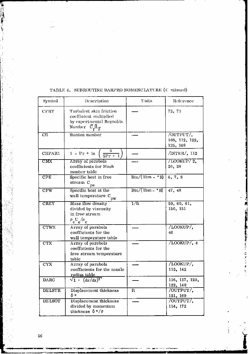
, TABLE 4. SUBROUTINE BARPRO NOMENCLATURE (C 'ntinued)
) Symbol Description Units Re fete'nee
CFRT Turbulent skin friction -- 72, 73
eocfficie.nt multiplie.dby experimental Reynohls
m
" Number CfR_
. CtI Stanton number -- /OUTPUT/,
108, 112, 122,125, 168
. .,. CtlPAR1 1 - _ /INTER/, 112
" :: _"--A-_ray o para o a --- _--coefficients for Mach 20, 28number table
:i' 'i'iil. CPE Specific heat in free Btu/(lbm - °IR) 6, 7, 8stream C
.... pe
•' ':' CPW Specific heat at the _ lbm .. ° R_ 47, 48" : wall temperature C
.. pw
:"":_" CREY Mass flow density _ 59, 60, 61,::i",:...:.:.:.:....:: divided by viscosity 150, 151" ;..;L
in free' stream.....
.... -;!. PeUe//_ e
.:::.':i:: CTWX Array of parabola _ /LOOKUP/,":"!*': coefficients for the 46
": wall temperature table
" _:.'- CTX Array of parabola _- coefficients for the _
: free stream temperature
table ._
CYX Array of parabola _ /LOOKUP/, .*coefficieDts for the nozzle 115, 142radius table
DARC _rl + (dr/dx)2_ -- 116, 117, 120,122, 140
DE LSTR Displacement thickness ft /OUTPUT/,6 * 151, 169
DE LSOT Displacement_thicknes s
• .:. divided by momentum 114, 172•. -. thickness 5"/0
' i ._
I
, 56
00000002-TSA07

:_: TABLE 4. SUBROUTINE BARPRO NOMENCLATURE (Continued)
Symbol Description Units Referenc e
DELTA Velocity thickness 6 ft /OUTPUT/, 167
DFLAT One-half the local drag Ibf/ft z 128, 130, 138,force normal to x-axis 148
,_ DFLATO Saved value of DFLAT lbf/ft 2 129, 148DFORCE One-half t.kc local drag lbf/ft 133, 147
.. force (for axisymmetricflow) or
(for two-dimensional lbf/ft 2 128, 137, 138, 147
.. planar flow).... DFORCO Saved value of DFORCE lbf/ft z 128, 147
:: " i . .. DX Weighted difference of ft /INTER/, 141,table values of axial 142, 144
•:i! dista nee
::.. .: ..--.'!. DXLARC Increment of the length ft li4, 145, 146, 147,' along contour 148
• DXRHO One-tenth the difference ft /INTER/, 13, 28,'-:-- :::":_:? between axial distance 31
:?:.. |
.. ::...:, :.:. EPSZ Geometry indicator m /INPUT/, 118,
:::_:(:i"."::"(":-: EPSZ = 0: two- 119, 130 /8.. : ..... dimensional _: :. i, planar flow
1
" .-.:: :!::i EPSZ = 1: axisymmetric• ..:: flow
...:!::,... _: ERASE1 1. Free-stream Maeh m 20, 21, 28, 29
:: _:!:. number M
/T _ 62, 63, 72, 83_. '., 2. Saved value of Taw e ,_.3 Saved__v_lue of 113, 119, 120. 122
1 d(0eUe) *or
pU dxe e
1 d(PeUe) ! dr
Pe Ue dx r dx
4. =r ft 131, 132, 1335. Contour radius r ft 142
57
00000002-TSA08

f
2: ¸
r}L
TABLE 4. SUBROUTINE BARPRO NOMENCLATURE (Continued)
Symbol Description Units Reference
:i ERASE2 1. Gradient of free- 1/ft 20, 28
!i stream Mach number:. dM /dxc
2. Saved value of m 63
3. Saved value of 1/ft 114, 120
1 + .6 */0 dUe
U dxe
4. Enthalpy difference ft2/sec 2 121, 122
H -H:::i:; 0 W
_: 5. dr/dx m 142_ 143ERASE3 i. Specific heat at _ 36
adiabatic wall
temperature C: paw
2. Saved value of 17.2 -- 64, 74
(W - Taw)/To aw F
ERASE4 Saved value of 305 -- 65, 74
(T - T o)/T ._:e aw
FJ Conversion factor (ft-lbf)/Btu /INPUT/, 125between thermal and
work units
FJG Conversion factor lbm/(Btu-sec 2) /CSEVAL/, 7,between thermal and 48
work units multiplied byacceleration of gravityused as a proportionalityconstant gJ
t
t
58 t "
Ir
00000002-TSA09

1"7i
$.
i!i ' TABLE 4. SUBROUTINE ]3ARPI{O NOMI,NCLA I [ RI_ (Continued)'t
i
" Symbol Description Units l{olToroneei
i FLAT Force normal to x- tbf /el I'1'1_lI'P.,/,I. direetionAor two- 148, -I71. dimensional plan'u" flow
'i ,: FORCE Drag-_oreo ha axial or lbf "...... /(TiS'i;OfVFT-(..........
x-direction I.t7, i 7 0G Acceleration of gravity lbmTJl_f- /INIqIT/, 11.7,
used as a proportionality ft/sec 2 125e ons tant
GAME Specific heat ratio in _ 8" free stream
•. tt0 Stagnation enthalpy II _t2/sec 2 /CSEVAL/, 9,: O
' .... 55_ 121' ..: HAW Adiabatic wall ft2/scc 2 35, 36, 39,
_ ' :. : enthalpy H 122, 1.25'_:. aw
• . ...
•" HE Enthalpy of free stream ft2/sec 2 /INTER/, 6,....'.::..::;_. in work units 1t 9, 35
"" e
::,::.".i_ HEP Enthalpy gradient ft/sec 2 7, 11, 40....!.-.:..:::: dH /dx
•-_'.._.- ' •".;.. e
:. ... .... . _,_,',.' : _.:... HG Heat transfer Btu/(ft2-sec _ R) /OUTPUT/,
1
" " "' coefficient h. 126, 167' .-: g
::_i_- i:: HW Enthalpy at the wall H ft2/sec 2 /INTER/, 39,• .:.. : .L '. 4"" W
:. : .... • 121, 122, 125
!.;. 'i::.":i;" HWP Enthalpy gradient ft/sec 2 40, 44, 48•: dH /dx _:•"= " W
• . I Subscript counter _ 153, 160, 168-172
ICFCH Option indicator _ 66, 7-1, 79,101, 106, 110 .'-
IMX Mach number table entry _ /LOOKUP/, 2,indicator and saved 20, 28subscript counter
IND Program loop control -_ CALL, 1, 123, indicator
:.. , .." .
-" , _ '..
59
p. . .. '..-
L .-. " _ '¢:. _._:_ ' I _..11___. _l_l_7-:alt!_,_-_ ............ ' -----_-_ _ *_, _ ...... _ - ......... '
00000002-TSA10
i!!
, I
t
bj,i
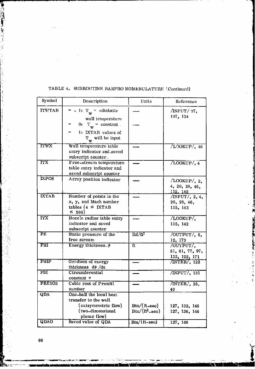
'.!i TABLE 4. SUBROUTINE BARPRO NOMENCLATURE (Continued)
Symbol Description U nits Reference
t ITWTAB = - 1: T = adiabatic -- /INPUT/',]7tw
wall temperature 1.07, 124
= 0. T = constant. .--w
= 1: IXTAB values of
T will be inputw
ITWX Wall temperature table -- /LOOKUPI/, 46entry indicator, and-saved
subscript counter_
ITX Free-stream temperature -- /LooKIJ'i_], 4
table entry indicator and
: saved subscript counter'IXPOS -
Array position indicator _ /LOOKUP/, 2,
4, 20, 28, 46,115, 142
IXTAB Number of points .in the /INPUT/, 2, 4," x, y, and Maeh number 20, 28, 46, ]
:: _:_ tables (4 -< IXTAB 115, 142q
::/i: • _ 500)
:" _. IYX 'Nozzle radius table entry -- /LOOKUP/,. indicator and saved 115, 142
" ' subscript counter
ll,(.: ;: PE Static pressure of the lbf/ft 2 /OUTPUT/, 5,::i!:i: free stream 12, 173
.... PHI Energy thickness_@ ft /OUTPUT/,
_. 51, 61, 77, 97,• . 112, 122, 171
PHIP Gradient of energy _ /INTER/, 122thickness d@/dx
PIE Circur_ferential __ /INPUT/, 131
L,,, constant 7r :_PRE103 Cubic root of Prandtl u /INTER/, 35, "
number 40
QDA One-half the local heattransfer to the wall
(axisymmetric flow) Btu/(ft-sec) 127, 132, 146(two-dimensional Btu/(ft2.-sec) 127, 136, 146
planar flow)
QDAO Saved value of QDA Btu/(ft-sec) 127, 146 ..
6O
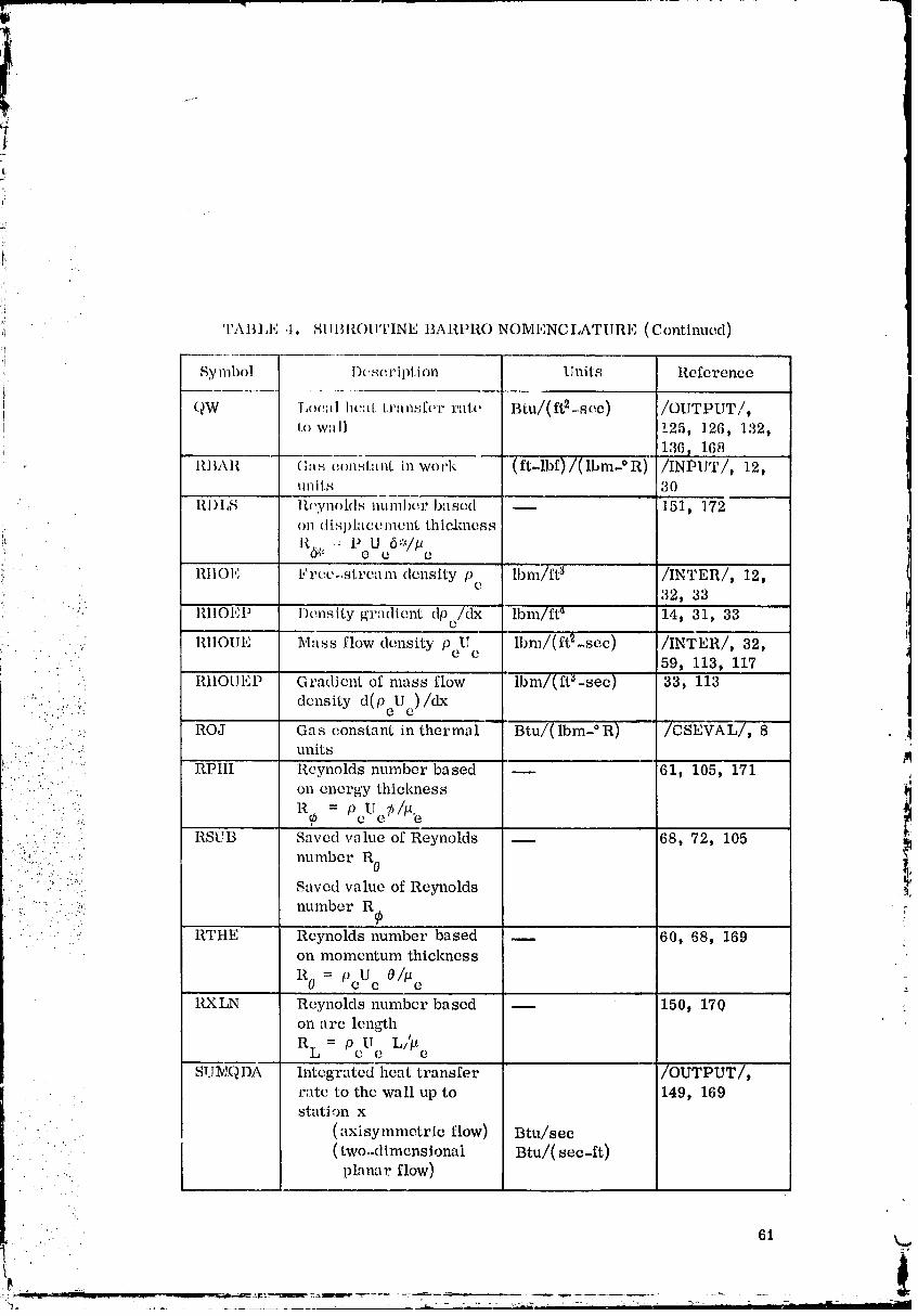
IAI LI, .[ SIIBllOII'rlNE BARPRO NOMENCI,ATIIRI,] (Continued)d_j
Symbol l)(mcription Units Reference
QW lxma] heal transfer r'fl:(, Btu/(ft2-soc) /OUTPUT,/,fJ Iowall 125, 126, 132,
136 _ 168lll_Al.l G ,s c(mStant in work (ft-lbf)/(lbm-°R) - /INPUT/, 12,
units '30
RI)I,S II(,ynohls number bas(2cl "-- .... 15i_ ]i;72.......on (lisl)htccm(2nL thiakness
:i. 1_.6_,_ , P U 6*/p", O {_ {2
" Ill|Of", Fr(2(2-stroam density p lbm/ft 3 /INTER/, 12,(2• :. 32, 33
";.' RIIOEP D(2nsity grqdient dPc/dX "'ibm/ft a "' 14, 31, 33
, ,. RIIOUE Mass flow density PeU lbm/(ft2-sec) /INTER/, 32,'" ,. " ', e
..'. , 59, 113, 117RtIOUEP Gradient of nmss flow lbm/(ft_-sec) 33, 113
.......-.. ._. density d(PeUc)/dx
._.. ROJ Gas constant in thermal Btu/(lbm- ° R) /CSEVAL/, 8' :.:" .........' units, • . . .
"i"... ' :: .... RPItI Reynolds number based -- 61, 105, 171:. :..)".: : .:., on energy thiclmess
........... : 7,/u=pUR@ c e
• . 5,'.
RSUB Saved value of Reynolds 68, 72, 105
•.. .:...'.i.:..-..-. number R 0•. .j..._". .. ? :
' .,- ' "... :"*... Saved value of Reynolds
.....' • ',,. number R@_'. . .........
. . - .....- ..-. R'I'ttE Reynolds number based _ 60, 68, 169 :_on momentum thickness
R 0 = PeUe 0/_e
RXLN Reynolds number based -- 150, 170 :on arc length
= U L//_RL Pc e e
SUlv[QDA Integrated heat transfer /OUTPUT/,rat(2 to the wall up to 149, 169stati,'m x
•. (axisymmetric flow) Btu/sec
• : ' ( two-dimcnsionai Btu/(see-ft)planar flow)
61 k.,
00000002-TSA13
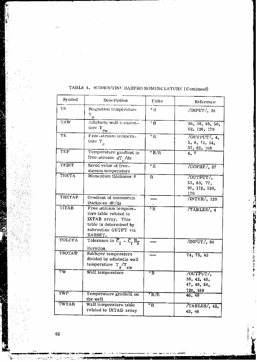
TABLE 4. SUBROUTINI,: BARPRO NOMENCLATURE (Continued)
Symbol Description Units Reference
T0 i Stagnation temperature. ° R /INPUT/, 34q'
O
TAW ,\diai_i_i:iC wall tempera- ° R 36, 28, "49:" 50,
, ture T 62, 126, 170
WE Free-stream tempcra- o a' /OUTPUT/, 4,. ture T 5, 6, 12, 34,
e 57, 62, 168
TEP ..... Temperature gradientin °R/ft' 4, 7
_ " free-stream dT /dxe
• • " : TFINT Saved'value of free- -°R /COFIIF/, 57stream temperature
•. THETA Momentum thickness 8 ft /OUTPUT/,
: 51, 60, 77,• . • . ..
• :_:. 97, 112, 120,....._:.• 170
:":..-.:.y-'=;:"::. . . .-. q
•."'" THETAP Gradient of momentum -- /INTER/, 120 :._• ...... .
: .... thickness dO/dx , lm
: :_':(:: :" TIVrAB Free..stream tempera- ° R /TABLES/, 4 _:_:.:Y :.: • ture table related to _i
1
•' IXTAB array. This
" '.i. table is determined bysubroutine GETPT via
:": ..... BARSET.
..: .. :,. i::. ToLcFA Tolerance in _f - _f--R_ _ /INPUT/, 84
' ' :' , _.: iteration _:.._. - . ' :...... , .... .-..
:::... TSOTAW Sublayer temperature _ 74, 75, 83 _.divided by adiabatic wall .v
temperature T /Ts aw
TW - Wall temperature °R /OUTPUT/, --38, 42, 46,
47, 49, 50,
126_ 169TWP Temperature gradient on ° R/ft 46, 48
the wall
TWTAB Wall temperature table °R /TABLES/, 42,
• . . related to IXTAB array 43, 46
O0000002-TSC01
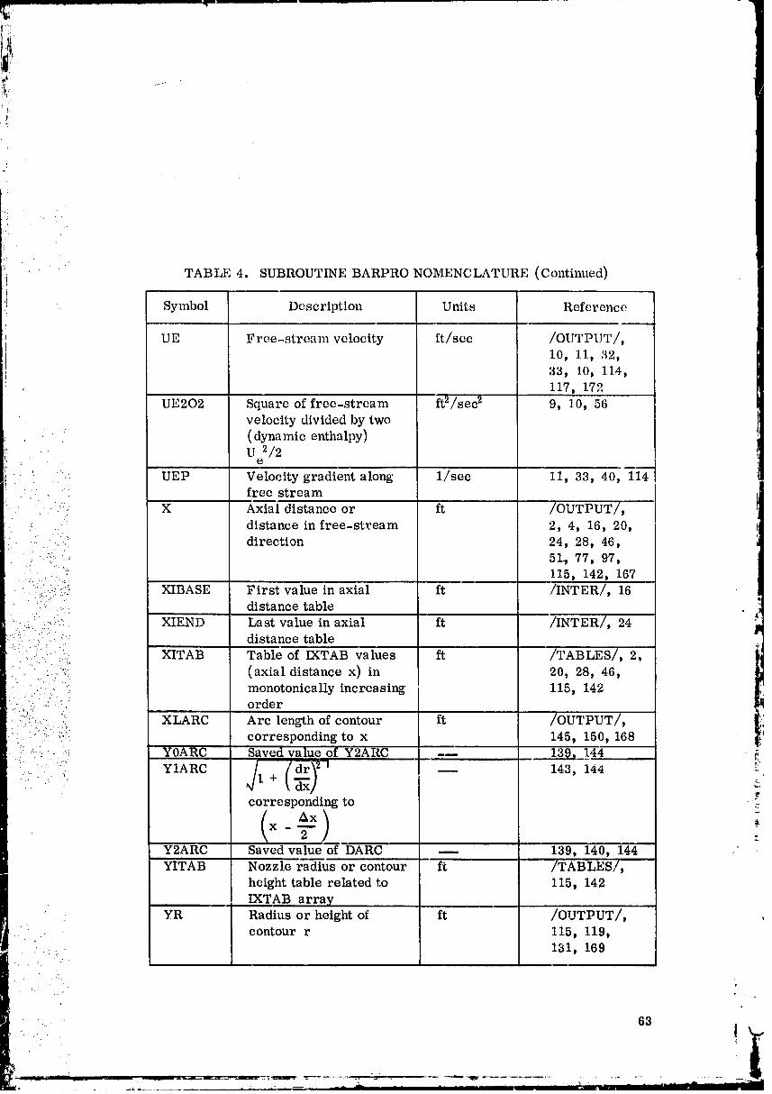
t
TABLE 4. SUBROUTINE BARPRO NOMENCLATURE (Continued)I ....
'_ Symbol Description Units Reference
UE Free-stream velocity ft/sec /OUTPUT/,10, 11, 32t
33, i0D 114,,_ II7D 172
UE202 Square of free-stream ft2/sec2 9, 10, 56veloci£ydividedby two
(dynamie enthalpy)U 2/2
e
UEP Velocity gradient along 1/sec 11, 33, 40, 114' " free stream
• .:":": X Axial distance or ft /OUTPUT/,
• .:. distance in free-stream 2, 4, 16, 20,
" ._....-i_: direction 24, 28, 46,.. 51., 77, 97,
..... 115, 142, 167: _"/::" _: XIBASE First value in axial ft •/INTER/, 16
..... distance table :,::i:. :':":, :i!. XIF__D Last value in axial ft /INTER/, 24
distance table
_..,* :.... XITAB Table of IXTAB values ft /TABLES/, 2,
: ':...:-: (axial distance x) in 20, 28, 46,• " .:_-:: " monotonically increasing 115, 142: ::./'_i!.:i/_ : order
.:!.:*.(..:i.._ :'i: XLARC Arc length of contour ft /OUTPUT/,
i.... " /! :.;': correspondingto x 145, 150, 168_::_:i_.._ YOARC Saved value of Y2ARC -_ 139, 144
'•" •'•'" YIARC "1 /drY2| 143, 1_4 _"
corresponding to • ?._.
( ) -&x _X - T _
Y2ARC Saved value of "DARe _ 139, 140, 144
YITAB Nozzle radius or contour ft /TABLES/,height table related to 115, 142
IXTAB arrayYR Radius or height of ft /OUTPUT/,
i..-., contour r 115, 119,: .: :. - 131, 169
. 63
00000002-TSC02

TABLE 4. SUBROUTINE BAR, Re NOMENCLATURE (Continued)
Symbol Description Units Reference
YRP dr/dx -- 115, 116, 119,
.... 138, 170Z1 1. Saved value of free- lbm/ft 3 ]7, 22, 31
stream density pe
2. Saved value of Cfag -- 90, 98
3. Saved value of -- /OUTPUT/,
'!! [ I 1 = (ZI1)or 154, 161, 168_ i 14 = (ZI4)
": Z2 1. Saved value of Pe lbm/ft_ 25, 30, 31
(( 2. Saved value of _ 87, 92, 94, 98
:i- Cfag (CFAG)3. Saved value of integral -- /OUTPUT/,
12 = (ZI2) or 155, 162, 169
• Is : (ZI5)
Z3 1. Saved value ofone or -- 18, 23, 26, 31 '__: point five_'.-:
_: 2. Saved value of Cfa -- 89, 98•:::: *
3. Saved value of integral _ /OUTPUT/,I3 = (ZI3)or 156, 163, 170
1
_; 16 = (ZI6)....: Z4 1. Free-stream pressure lbf/ft 2 21, 22, 29, 30
Pe
::: 2. Saved value of -- 86, 91, 94, 98
Cfa (CFA) i'_£
3. Saved value of integral /OUTPUT/,I{ = (ZI2P) 157, 164, 172 ;
Z5 . 1. Free-stream tem- °R 21, 22, 29, 30perature T "-.
e
2. Saved value of -- 93, 94(z4 - z3)/(z2 - Zl)
3. Saved value of integral -- /OUTPUT/,
I_ = (ZI1P)or 158, 165, 172
I_ = (ZI3P)ZETA Shape factor: -- /OUTPUT/,
= (A/8)n 152, 167 ,.
- !z,
64 _i
00000002-TSC03
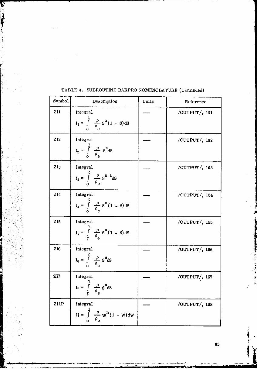
TABLE 4. SUBROUTINE BARPRO NOMENCLATURE (Continued)
, Symbol Description Units Reference
ZI1 Integral -- /OUTPUT/, 1611
II= f --Psn(1 - S)dSo Pe
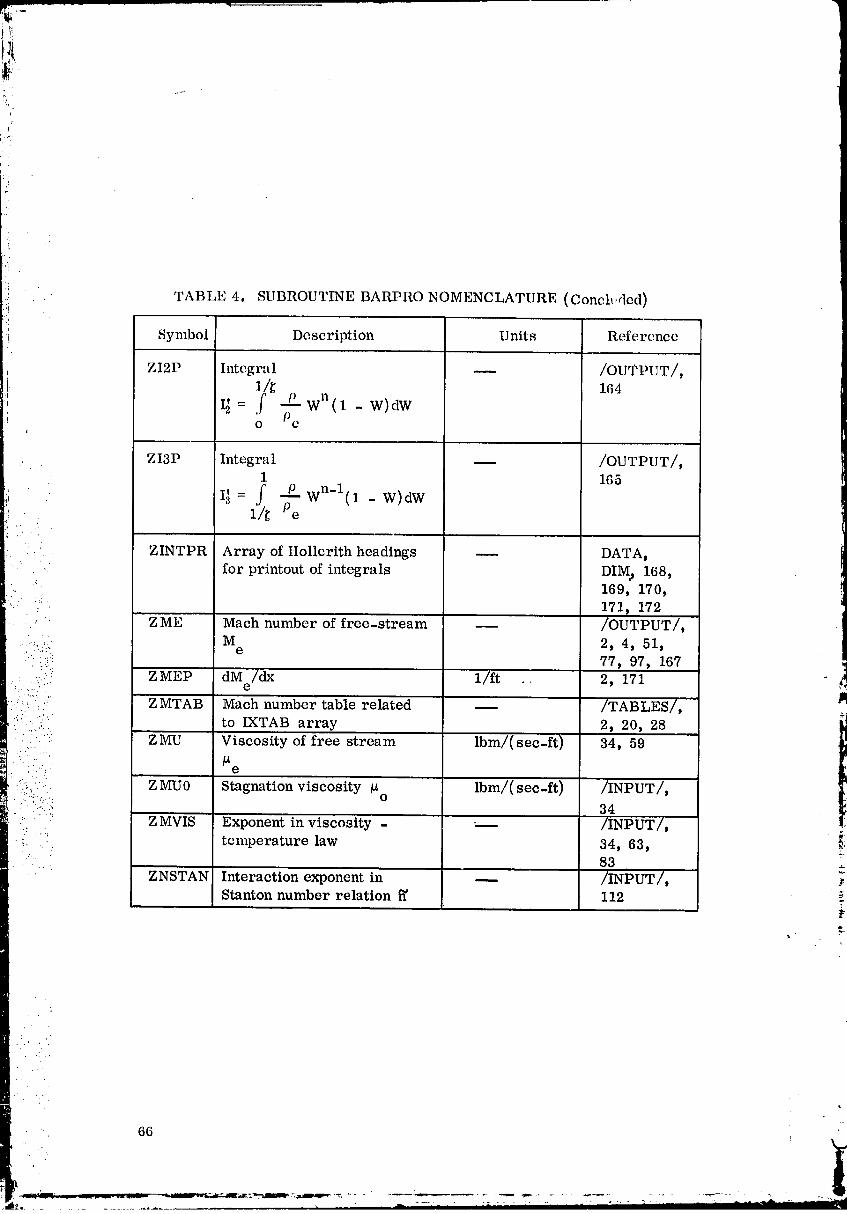
ii TABLE 4. SUBROUTINE BARPRO NOMENCLATURE (Conclttrled)
., Symbol Description Units Reference
+ ZI2P Integral -- /OUTPUT/,i 1/_ 164
I I_ = f -£-P wn(1 - W)dWi o Pe
i
ZI3P Integral -- /OUTPUT/,1 165
+! I] = f P W n-l(1 - W)dW:'+ 1/_ Pe! .-. . .
:. ZINTPR Array of Hollerith headings -- DATAt
for printout of integrals DIM, 168,• 169, 170,' .-/
171, 172
• Z ME Mach number of free-stream -- /OUTPUT/,
...::.._,/:: Me 2, 4, 51,:+:; 77, 97, 167
-::,... ZMEP dM /dx 1/ft .. 2, 171
::.:_.:.:/:j: ZMTAB Math number table related __ /TABLES/, iR:'.... to IXTAB array 2, 20, 28• :: ': ZMU Viscosity of free stream lbm/(sec-ft) 34, 59+ . ......,
• " " e
I -::+:_ Z MU0 Stagnation viscosity _ Ibm/(sec-ft) /INPUT/,+".". O
.... -'".':- 34
":'" " °" Z MVIS Exponent in viscosity - -- /INPUT/,
i. '_ temperature law 34, 63, _i.. 83
ZNSTAN Interaction exponent in -- /INPUT/, ;Stanton number relation _' 112
• ....
00000002-TSC05
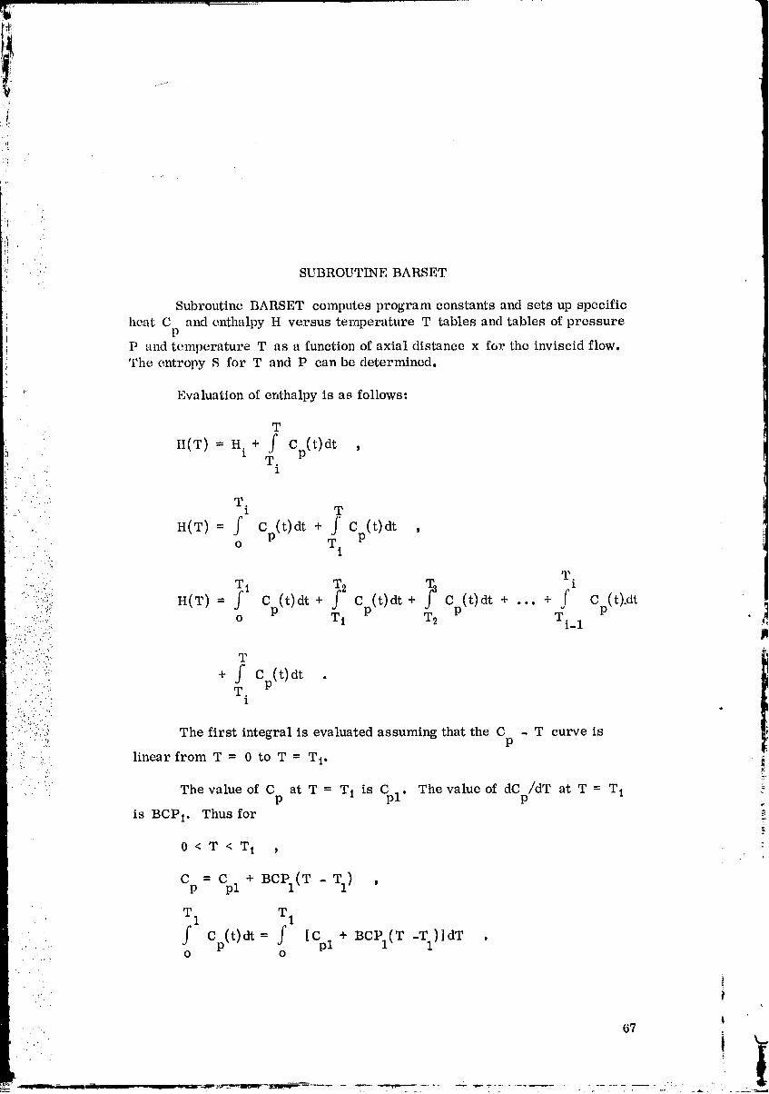
V
:4-
i
SUBROUTINE BARSET
' Subroutine BARSET computes program constants and sets up specific
heat C and enthalpy H versus temperature T tables and tables of pressurep
P and temperature T as a function of axial distance x for the inviscid flow.The entropy S for T and P can be determined.
' Evaluation of enthalpy is as follows:
W
It(T) = H.1 + f Cp(t)dt ,T.
• - 1
' T,
z T
- " H(T) = f Cp(t)dt + J' Cp(t)dt ,O T.
1r,
- T.
'" _ Cp(t)dt _ p(t)dt _-3 p(t)dt _" Cp(+ c + • c + ... + _ t)_dt
:, ..... o T 1 T 2 Ti_ 1::-, .::......_..
:.:' .i ':,::'i T
" f Cp(t)dt• ." • .
' T°
: : .,,.,' The first integral is evaluated assuming that the C - T curve is:_ ::: P
..... linear from T = 0 to T = T i.
" . The value of C at T = T 1 is C The value of dC /dT at T = T 1 :-p pl" p
is BCP t, Thus for r
0<T<T i _ :
Cp- Cpz+Bcpz(T- TZ)T 1 T 1
.. f Cp(t)dt = f [Cpl + BCPI(T-T1)]dT .o O
i
.,
67
00000002-TSC06
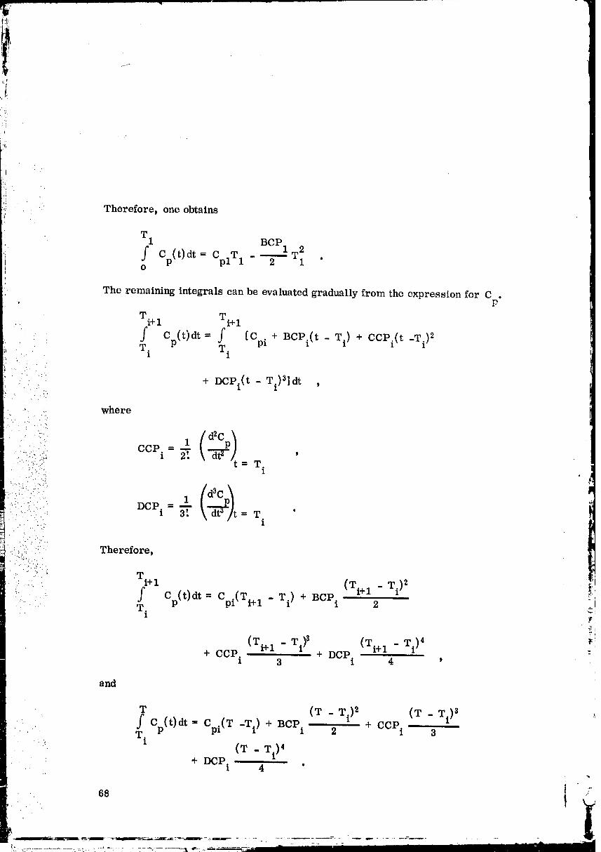
Therefore, one obtains
00000002-TSC07
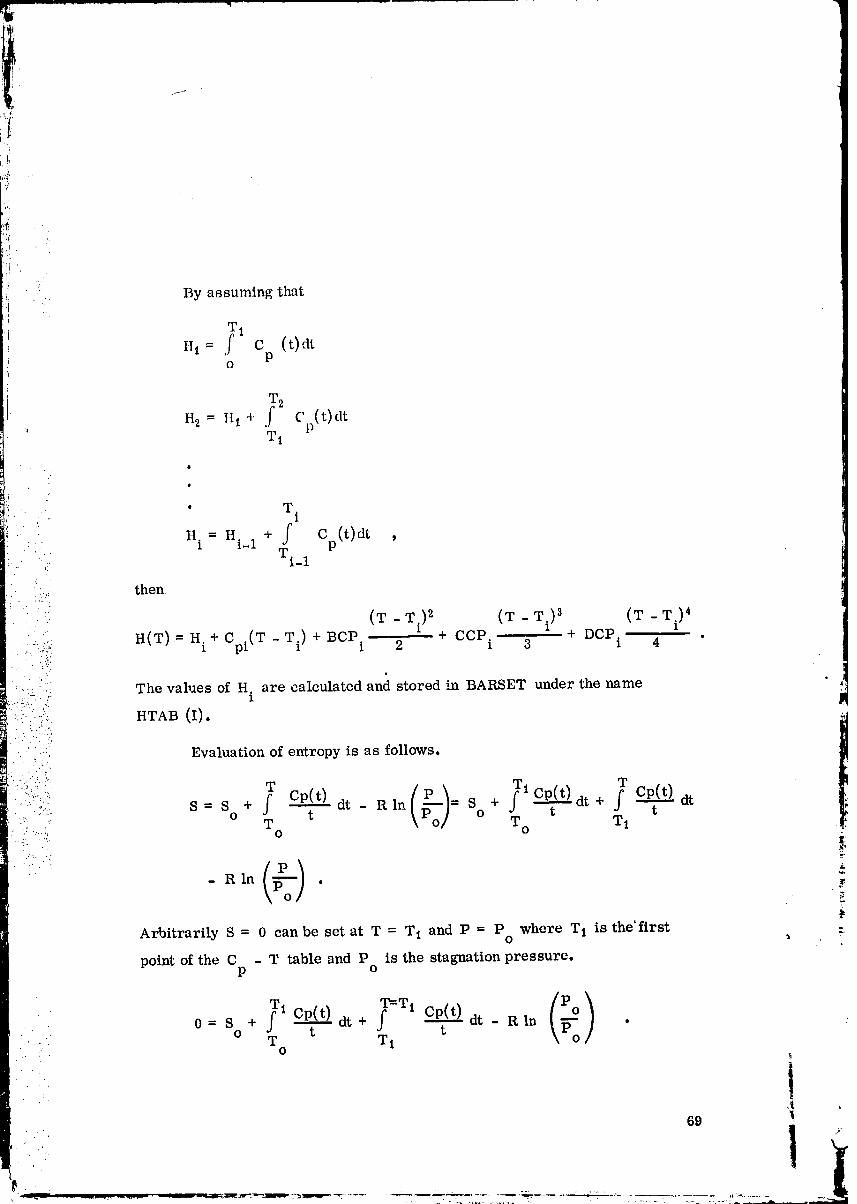
Ii .._°
•i!
'. By assuming that
, T1i ,,,--f c (t)dt
Po
W 2
,_ H2 = H 1 4-f Cp(t)dt, T1
[ •
' T• . t 1
_ t,. =Hi + f Cp(0at:!, Ti_1
.... then.}.
(T - T.) 2 (T - 3 (T - Ti)4- .. 1 Ti)
H(T) = H.+ Cpi(T -Ti) + BCP. + caP + DCP.i I 2 i 3 I 4 "
, . . :[..
:.. .......: The values of H. are calculated and stored in BARSET under the namec...:,..._.. ;. I
_i ::i,-},:i" '/!:i.:7)_, HTAB (I). _T Cp(t) (X lp-'-_ T o T i i
•' " Evaluation of entropy is as follows.
s - s + o dt - a In___-- so + dt+ dt-:: " " O t _PO ] t
<) .w.- Rln
Arbitrarily S = 0 can be set at T = T t and P = P where T 1 is the'firstO
point of the C - T table and P is the stagnation pressure.p o
_1 Cp(t) ?Ti Cp(t) (_)
• 0= S + dt+ --dt - Rln •
. o T t Ti t• .7.. O
i69
00000002-TSC08
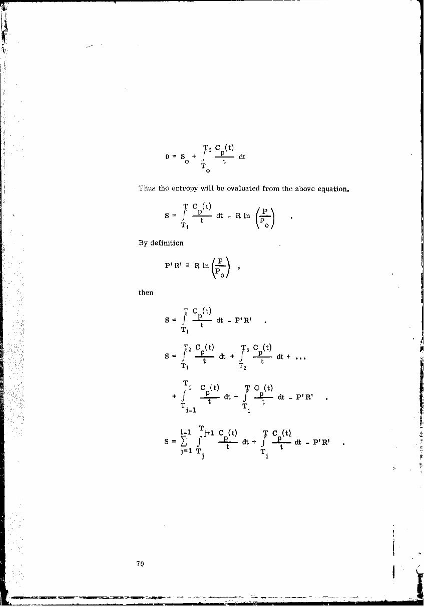
Thus the entropy will be evaluated from the above equation.
T C (t).: S = ( P_ dt - Rln [t_ _
J
t _Po]Ti
By definition
P' R' = R In (p-_)
then•.::.
_._:_ S = f dt - P'R' .? ,. T1
::-: _ Cp(t) _ Cp(t) ,_/-i: ._ 2 3. S = -- dt + -- dt +
'* :: t t "'": : : T1 T2
:i.! I.)ii' _i. + j dt + dt - P'R'
/' :: :)iii: Ti_l Ti t "
..:. rj.',l
S = dt + dt - P'R' . ,'_._-,,:
j=l T. T i _'D
I
70
00000002-TSC09
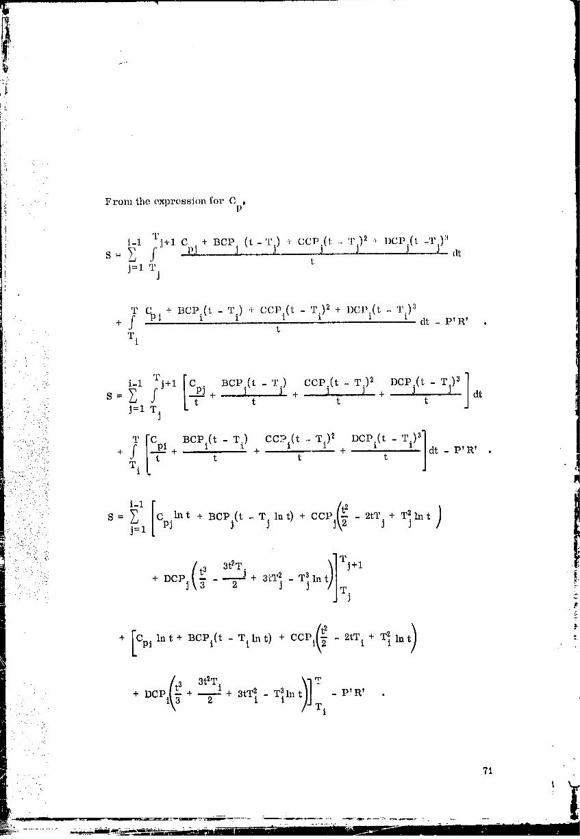
t 3 3t2T i+ DCP + _ + 3tT 2. - T_ln - P'R' •
1 Ti
, .'..
71
O0000002-TSCIO
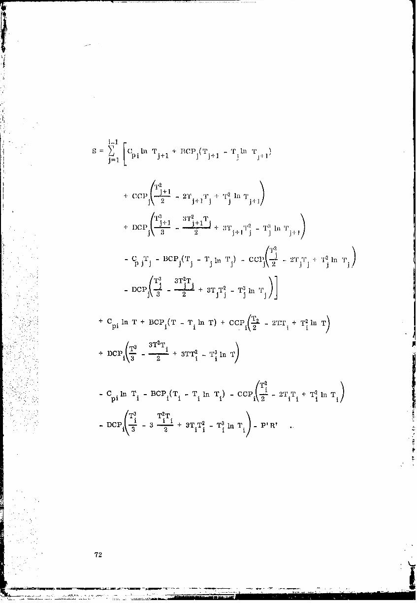
72
t
00000002-TSC ] ]
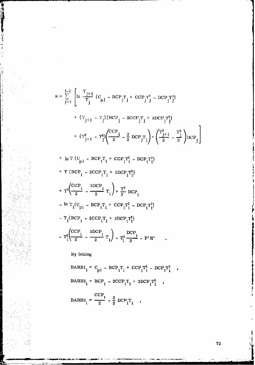
i .....
A.
j'
" [ 'r (:il i-1 j+l
S = J'=]_ [ln -_j Cpj - BCPjTj + CCPj.jq'2 .- DCPjT])
+ (q?j+] " Tj)(BCIJj - 2CCPjTj + 3DCPjT])
(c i - ncp_Ti _DCPiT_i).: 1 1
+ T (BCP.1 - 2CCPiTi + 3DCPiT_)
"-. ' /CCP. 3DCP. ) T3- : ' _ + T2_ --'--_1T i + DCP....' '.,"
_..., - lnTi(Cpi _ BCPiT t + CCP.T2.11 - DCPiT3i)
:.:i : " - Ti(BCP i - 2CCP.T. + 3DCPiT_) i".'.i':: . .:, .:. 1 1
, ..... /ccp. 3Dcpi ) DcP.• .:""!:.':. " ".....•.::: 2 "'---" - ".....,... ....
.,: " .:,:.-:_.::i:i:i:,::...... . : ._
..... " By letting. . i". - . ." :" ". / .
1 pi ' :
BARB2 i = BCP. - 2CCP.T. + 3DCP.T 2. ,1 1 1 1 1
ccp. i, 3
BARB3. = _- - -- DCPiT i1 2 2
• .:' . .....
• . ...
s
73 ,_
00000002-TSC13

then
i-i [l T (Tj+
\, j+J.: n _ BARB1. + - T.) BARB2.
S ._1 T. J 1 J Jj :1 j
-I
,: ' ( , .9.L .t ,.i_ ,_,2)j I_A 1_]_3 .j _,. ,r],Zj.,. J- ¢[,3,_ _1'_ t_J J
DCP.+ lnT BARBI.+ T BARB2. + T 2 BARB3. + T3
1 1 1 3
DCP.
- in T. BARB1. - T. BARB2. - T 2.BARB3. - T 3. 1 _ pVR, .• " 1 1 1 1 1 1 1 3
' The terms G1 ap_d G2 are defined as follows:
i- 1 [i T j+ 1 ( T j+ 1' :.:'.::_ G1 = _ n T BARB1. + - T.) BARB2.
.... J i
•,.._..- DCP.':".- " + (TI+ 1 - T2.) BARB3 + (T 3 - T3.) J'" '::: .1 j j+l ] 3 "
....-
;-:,: DCP..-?i..i G2 = In T. BARB1. + T. BARB2. + T 2. BARB3. + T 3 _ .
.... 1 1 1 1 x 1 i 3. ".'-:
.: ..... Then
-.. T3DC P. !S = G1 +in T BARB1. + T BARB2. 2BARB3. + 1 G2 - pVRv . z
1 1 1 3 ._T
By letting
G. = G1 - G2 ,1
74
00000002-TSD01
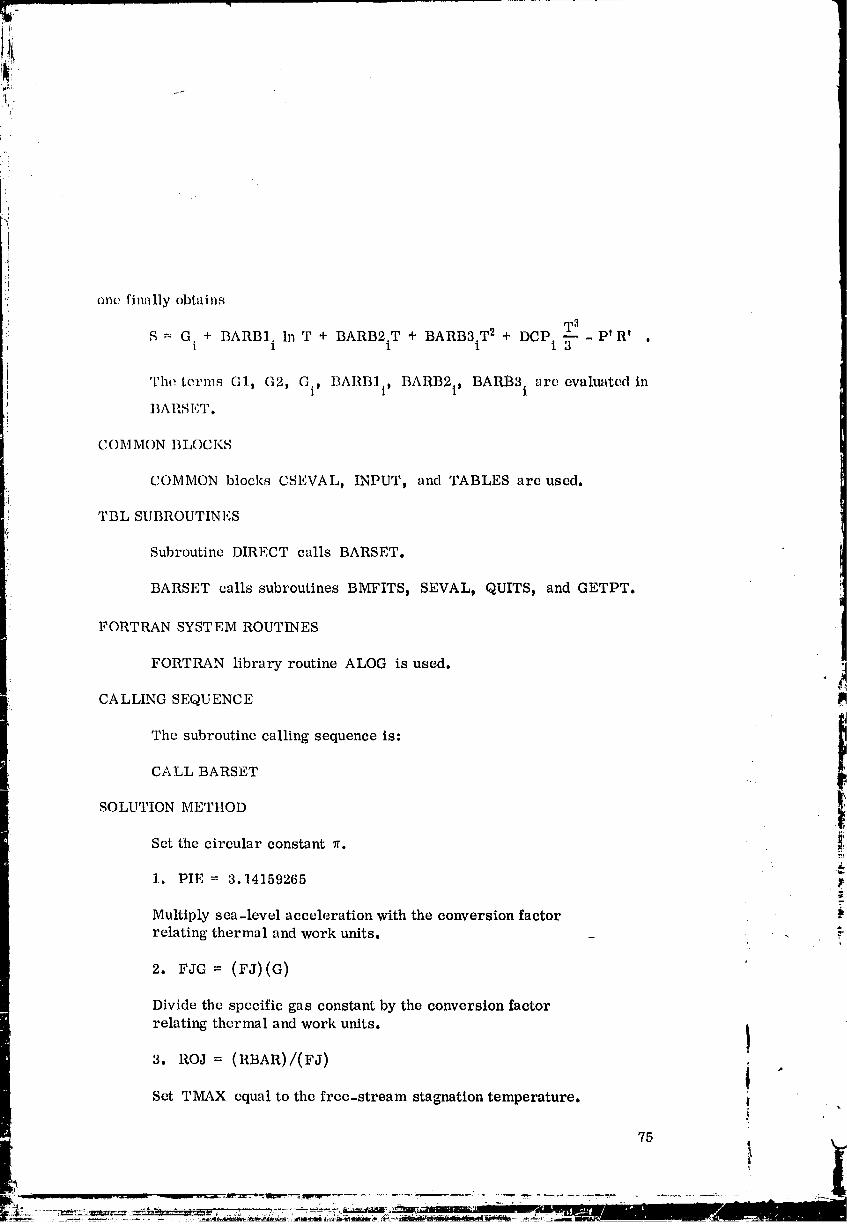
i
:: one finally obtainsI
BARB 3i T2 T '_S = G.] + BARBI.1 In T + BARB2.T1 + + DCPi __. _ptR t .
'I'h(_ terms G1, G2, Gi, BARBli, BARB2i, BARB3 i are evaluated in
BARSIr, T.
COMMON BLOCKS
COMMON blocks CSLVAL, INPUT, and TABLES are used.
TBL SUBROUTINES
Subroutine DIRECT calls BARSET.
BARSET calls subroutines BMFITS, SEVAL t QUITS t and GETPT.
FORTRAN SYSTEM ROUTINES
FORTRAN library routine ALOG is used.CALLING SEQU ENCE
The subroutine calling sequence is: i
CALL BARSET iSOLUTION METHOD
Set the circular constant 7r. !:
1. PIE = 3. 14159265
Multiply sea-level acceleration with the conversion factor brelating thermal and work units. _
2. FJG = (FJ)(G)
Divide thc spccific gas constant by the conversion factor
relating thermal and work units. !
3. ROJ = (RBAR)/(FJ) i "Set TMAX equal to the free-stream stagnation temperature, i
75
. ........... ,, _ _ _ .._._.- _w_,.....-.-_,,,_- w.......... -. .... :...--: ..,,- ?._.. - L -- ......_-- _ : ' .... "_*__" --_ " " .................... _--"_.... _':'--_'_" -,_ .----"-............* n /n_m nIN ......
00000002-TSD02
• ,'L
L
I4. TMAX = TO
Set indicator I1 for nominal entry.
,5, I1=1
Test whether adiabatic wall temperature (ITWTAB = -1),
constant wall temperature (ITWTAB = 0 ), or tabular well,p
temperature (ITWTAB = 1) i_ to be used.
6. If ITWTAB > 0, go to7!
If ITWTAB = 0, go to8
If ITWTAB < 0, go to 12".5,
: Set I1 equal to the number of points in x D y, and M tables (LXTAB).
" 7. I1 = IXTAB
• : iiiii::i_::: Check and save the maximum value of the wall temperature tabulated(TWTAB)
'" ::" "2' .".'.
?..... • . .:
:::::.i:::': ': 8. Do 11 I = 1, I1
...... : : 9. If TWTAB (I) < TMAX, go to 11• . , ,': ..
If TWTAB (I) _ TN__X, go to 10•.i.-: • '
.... Save the maximum value of TWTABo
._. -..: ...
• :: (1)'" 10. TMAX = TWTAB• ." ....-' . .
11. Continue.
Test whether constant specific heat calculation (ICTAB = 0 )
or specific heat table is required (ICTAB > 0).
12. If ICTAB = 0, go to 47
If ICTAB ¢ 0, go to 13
• " i
t
76 i
1
00000002-TSD03

i , Check whether the temperature input value (TMAX) exceeds the table.i upper limit.
i 13. If TMAX < TCTAB(ICTAB), go to 16
If TMAX _ TCTAB(ICTAB), go to 14
WRITg TCTAB(ICTAB) and TMAX, when the table upper limit' TCTAB(ICTAB) is exceeded.
14. WRITE TMAX, TCTAB(ICTAB)
Stop the calculation by callil_g QUITS.
15. Go to 49:
Save the number of points in C versus T table (ICTAB).:. P
16. NOCTAB = ICTAB
:_':? The following calculation, dowr_to step 43, is only used for specific":. heat polynomialj enthalpy, and entropy equations. Call subroutine
: :_ii:!. BMTAB to determine polynomial coefficients BCP, CCP, and DCP. __,... "-
:.'. ..,..
L .. 17. CALL BMFITS (TCTAB, CPTAB, ICTAB, BCP, CCP, DCP)
:. Calculate temperature and various powers thereof.
_. 19. TIE2 = (TCTAB (1) )2 !:
°2_). TIE3 = (TCTAB(1)) 3 "
Calculate the enthalpy at T 1.
21. HTAB(1) = (CPTAB(1))(TIE1) - (BCP(1))(TIE2)/(2.0) " :
A term in entropy equation
22. BARBI(1)= CPTAB(1) - (BCP(1))(TIE1) + (CCP(1))(TIE2)-
(DCP (1)) (TIE3)
77 -.
.p
00000002-TSD04
!•: ! • '"
iI
i
First derivative of the above equation with negative sign
23. BARB2(1 ) BCP(1) (2.0) (CCF(I)) (1 ILl)+ i,2IT,,"
¢Second derivative of the equnti(m 22 times (-0.25).
24. BARB3(1)::= ((CCI'(1)) -(3.01(I)(.'.l'(11)(TIE1)/(2.0)
First term of the entropy equation
25. GTAB(1) = -(BARBI (1))(Ln(TIE1)) - (BARB2(1))(TIE1)..(BARB3 (1)) (WIl,_) (DCP(1)) (TIE3)/(3.0)
Set entropy summation term to zero.
.: 26. G1 = 0.0
Store the enthaltpy and coefficients of entropy equation at eachtemperature cor.-'esponding to C - T table.
" ":_[: p
: 27. Do 43, I = 2_ ICTAB
:. Save TI= TIE1, T12 = TIE2_ T1 a = TIE3.:-"i_..;_.
..... 28. TME1 = TIE1
:i:_i:-_i:.- 29• TME2 = TIE2....:..
.:. " 30. TME3 = TIE3
.. Set new values from C - T table.p -.
31 TIE1 = TCTAB (I)• ._
32. TIE2 = (TIE1)(TIE1) -
33. TIE3 = (TIE1)(TIE2)
Determine the temperature difference (T i - Ti_l) O
34. DELT = TIE1-TME1
Enthalpy at temperature T. from C - T table•1 p
i78 _
00000002-TSD05
- I
,_! 35. ttTAB(II = ttTAB(I - 1) + (CPTAB(I - 1))(DELT)
+ (BCP(I- 1))(DELT)2/(2.0)+ (CCP(I - 1))(DELT)3/(3.0)
_,. + (DCP(I - 1))(DELT)4/(4.0)
Check whether the value of I equals or exceeds ICTAB.
36. If I >- ICTAB, go to 43
If I < ICTAB, go to 37
Determine the coefficients used in the entropy equation:
S = GTAB(I) + BARBI(I) Ln T + BARB2(I) W + BARB3(I) T2: + DCP(I) T3/3 - R Ln(P/Po).
•_ 37. BARBI(I)= CPTAB(I) - (BCP(I))(TIE1) + (CCP(I))(TIE2)- (DCP (I)) (TIE3)
First derivative of the previous equation
.:. 38. BARB2(I)= BCP(I) - (CCP(I))(TIE1)/(0.5)
i::i.:.. + (3.0)(DCP(I))(TIE2)
:::.-/......
• Second derivative of 37 times (-0.25)
39. BARB3(I) --(CCP(I) - (3,0)(DCP(I))(TIE1))/(2.0)
!/:::!':!i:_ Sum up terms in entropy equation.
: i: 40. G1 = G1 + (BARBI(I - 1))(Ln((TIE1)/(TME1))) _,... + (BARB2(I - 1))(DELT) -
+ (BARB3(I - 1))(TIE2 - TME2)
+ (DCP(I - 1))(TIE3 - TME3)/(3.0)T
41. G2 = (BARBI(I))(Ln(TIE1)) + (BARB2(I))(TIE1) -+ (BARB3(I))(TIE2) + (DCP(I))(TIE3)/(3.0)
42. GTAB(I) = G1 - G2
43. Continue
Determine the number of input intervals minus one.
44. IS = ICTAB - 1
Stagnation enthalpy Ile and specific heat Cpo are obtained from
subroutine SEVAL for a given stagnation temperature.
45. CAI,I, SEVAL(], T0, CP0, ti0)
C,dculation of specific heat ratio at stagnation point
= Cpo/, (7o (Cpo - ii/J)
46. GAM0 = (CP0)/(CP0 - ROJ)
• . When this specific heat ratio To is less than 1, check for iaconsistant
• units and stop the calculation. Otherwise continue.
•. : . .
47. If GAM0 > 1.0, go to 50
• ._ . •
: " ' If GAM0 _ 1.0, go to 48
.....:":' - 48. WRITE GAM0..... 7:."-::::':(
....: . .,
" ..... Subroutine QUITS stops the computation.• = ...
:'::: ,-... • 49. CALL QUITS _'_
1
:i ::' Set (_/o - 1)/2 as
• 7%: 50. GM102-- (GAM0 1.)/(2.): ! .¢_.
':. : 51. GOGM1 = (GAM0)/(GAM0 - 1.0)%. _'
' Save the stagnation pressure, t
52. P0MAX = P0
Generate the table of free-stream pressure P and temperature T .e e
1_ and T are obtained for a given M by using subroutine GETPT.e e e
53. Do 54, I = 1, IXTAB

!i " 54. CALL GETPT(ZMTAB(1), PITAB(1), TITAB(.Q)
i
' Calculation of the free-stream enthalpy in the ease of C = constant.
This calculation continues to step 85. P
55. If ICTAB > 0, gotoa5
,_ If ICTAB < 0, go to 56
•' Set
'' 56. NOCTAB = 6
• : Save NOCTAB minus one.2 .. •
: ' 57. NOCTM1 = NOCTAB 1• . m
m IP
: : " Save NOCTM1... • .j.
::, :: 58. IS = NOCTM1
_ _,:.: 70R:t:;:_.:..::; Compute the specific heat for stagnation condition C =
:,:_: ,::.: po J(7 ° - 1) "
: a9. cp0 -- (GOGm)(RBAR)/(FJ)" " 'L i'.
..} ' , "
:::i:(i:.iii:!:? Calculate the specific heat in work units C' - 7ogR
:1%:::= P Yo - 1• .,.
_:.!. ",'...:/: 60. CJG = (CP0)(FJG) _.? :.• : Compute stagnation enthalpy in work units.
61. H0 = (CJG)(T0)
If the free-stream temperature exceeds the stagnation temperature,set the former as TMAX.
62. Do 66, I = 1, IXTAB
: Set the frce-stream temperature equal to the table value T .• " ' ""' e
00000002-TSD08

¢-
' 63. TE- TITAB(I)
64. If TE -< TMAX, go to 66
If TE > TMAX, go to 65
_" Save T .e
I,
65. TMAX = TE
66. Continue
:. Set the maximum temperature in the table to TMAX plus a hundred.
-/"
67. TCTAB(NOCTAB) = TMAX + 100.0
i'_- Set the first temperature table value to 10 -l°.
68. TCTAB(1)- 1.0E-10
':':_ Obtain NOCTM1 as a real number.it..
!i::ii(:i.:!/::: 69. Z 1 : NOCTM1 $,L :.
$
. Definition of DELT ; TMAX + 100 - (1.0E - 10)• " _.!: 5
? 70. DELT = (TCTAB(NOCTAB) - TCTAB(1))/(ZI)
_ Compute first term in entropy equation..-,...,
.... • 71. ERASE1 = -(CP0)(Ln(TCTAB(1)) :.
c;Compute the coefficients for the specific heat polynomialand entropy equation. .*
72. DO 84, I = i, NOCTAB
Save ERASE 1.
73. GTAB(I) = ERASE1
00000002-TSD09
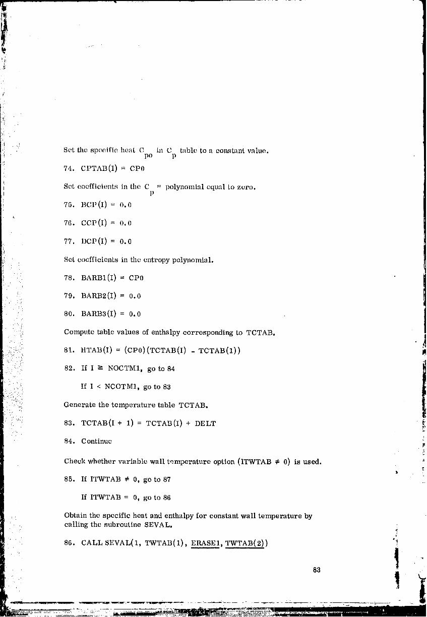
/
Set the specific heat C h_ C table to a constant value.po p
74. CPTAB(I)= CI)0
i Set coefficients in the C polynomial equal to zero.t =
I P7,5. Bc_(I)= o.0
0;
7¢_.coD(I)= 0.0
77. DCP(I)= 0.0
Set coefficients in the cntropy polynomial.
78. BARB1(1) = CP0
79. BARB2(1)= 0.0i.
80. BARB3(I)= 0.0
_' Compute table values of enthalpy corresponding to TCTAB.• ." J
ii.:iii.:!'_ 81. HTAB(I)= (CP0)(TCTAB(I) - TCTAB(1)) IA
: : '.: 82. If I _- NOCTM1, go to 84
1
::i'i: ,:'. If I < NCOTM1, go to 83
:/!i.;i. Generate the •temperature table TCTAB.
83. TCTAB(I + 1)= TCTAB(I) + DELT !:
84. Continue
Check whether variable wall temperature option (ITWTAB ¢ 0) is used.b
85. If ITWTAB ¢ 0, go to 87
If ITWTAB = 0, go to 86
Obtain the specific heat and enthalpy for constant wall temperature by.. calling the subroutine SEVAL.
86. CALL SEVAL(1, TWTAB(1), ERASE1, TWTAB(2)) °'_
83
00000002-TS[:)10
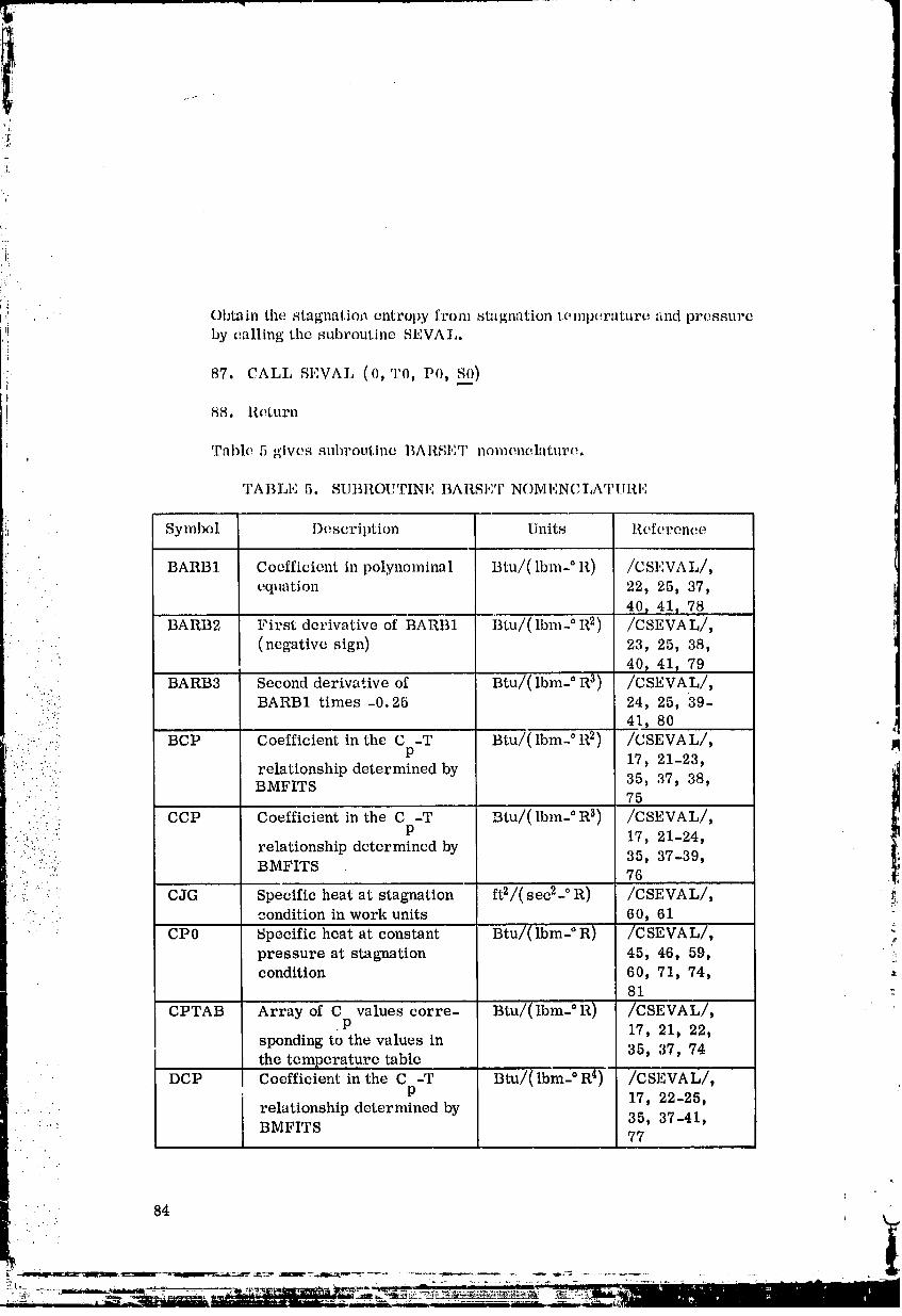
?L.5
°4
:iiL;_ '
i:,: Obtain the stagnatio_ entropy from stagnation temperature and pressure
_! by calling tile subroutine SEVAL.
87. CALL SEVAL (0, T0, P0, SO)I
88. Roturn
Table 5 gives subroutine BARSET nomencl,'ttur(:.I
TABLE 5. SU]]ROUTINE BARSE'P NOMENCLATIIRE
Symbol I) escription Units Reference
BARB1 Coefficient in polynominal Btu/( lbm-° R) /CSEVAL/,equation 22, 25, 37,
40_ 41_ 78BARB2 First derivative of BARB1 Btu/( Ibm- ° R2) /CSEVAL/,
: .. (negative sign) 23, 25, 38,
' • 40, 41_ 79
. '.;i. BARB3 Second derivative of Btu/( Ibm- ° R 3) /CSEVAL/,
..-::ii:I BARB1 times-0.25 24, 25, 39- !• 41, 80 .4
:i : :!:ii!i!!II'':_!:::::I BCP BMFITSCoefficientrelationshipindeterminedthe C -TP by Btu/( lbm-° R2) 7535,/CSEVAL/,17, 37,21-23_38, M"'CCP Coefficient in the C -T Btu/(lbm- ° R 3) /CSEVAL/,
relationship determined by 35, 37-39,BMFITS 76
CJG Specific heat at stagnation ft2/(sec2- ° R) /CSEVAL/, _:condition in work units 60_ 61
CP0 Specific heat at constant Btu/( Ibm- ° R) /CSEVAL/,pressure at stagnation 45, 46, 59, ,-_condition 60_ 71, 74,
81
I CPTAB Array of C values corre- Btu/(lbm- °R) /CSEVAL/,• P 17, 21, 22,sponding to the values in , ,
| - 35, 37, 74| the temperature table| ' DCP Coefficient in the C -T Btu/(lbm- ° R 4) /CSEVAL/,| " P 17, 22-25, '| . '. relationship determined by
I " ' BMF-_ 35_ 37-41,
-..... : I'r_ 77
| .i ". 84 ' i_
• : '! : i
00000002-TSD11
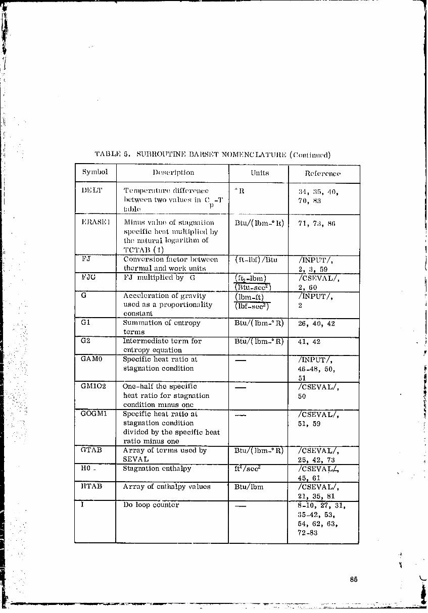
-7
• TABLE 5. SUI]ltOII'I'INE BARSET NOMENCLATURI.: (Conlinued)
Symbol l)(:,_cripl.ion Units Reference
1)ELT T(,mpc, ratur(! difft,ronco OR 34, :_5, 40,bctwoen two values in C -T 70, 83bfl)le P
I':RASE] Minus wllu(: of stagnation Btu/(lbm- ° R) 71, 73, 86spe(.ific, heat multipli(;d byth(: na tura i logarithm of
TCTAI(:I)FJ [ Conversion factor between (ft-lbf)/Btu /INPUT/,
thermal and work units 2, 3) 59
FJG FJ multipliedby G (ft2-1bm) /CSF,VAL/,(Btu-sec 2) 2, 60
G Acceleration of gravity (lbm-ft) /INPUT/,.. used as a proportionnlity (lbf_sec 2) 2
constant [G1 Summation of entropy Btu,/(lbm- ° R) 26 40, 42
•._:. terms
'i:' G2 Intermediate term for Btu/( lbm-° R) 41, 42 i
.... .:. entropy equationi."." GAM0 Specific heat ratio at _ /INPUT/,.:... . ..
• .. stagnation condition 46-48, 50,: ' 51
_, GM102 One-half the specific _ /CSEVAL/,:.:%.:.-. heat ratio for stagnation 50 "
'....;:._._ condition minus one-" ".... GOGM1 Specific heat ratio at _ /CSEVAL/,
_. .:. stagnation condition 51, 59...... • divided by the specific heat
• " " ratio minus one
....GTAB Array of terms used by Btu/( Ibm- ° R) /CSEVAL/,
SEVAL 25) 42, 73 -
It0 _ Stagnation cntha lpy ft _/see 2 /C SEVA LL, ,45, 61
HTAB Array of enthalpy values Btu/Ibm /CSEVAL/,
21, 35, 81I Do loopcountcr _ 8-I0, 27, 31,
35-42) 53,
54, 62, 63,.... 72-83
..'. 85 k_
i
00000002-TSDI 3
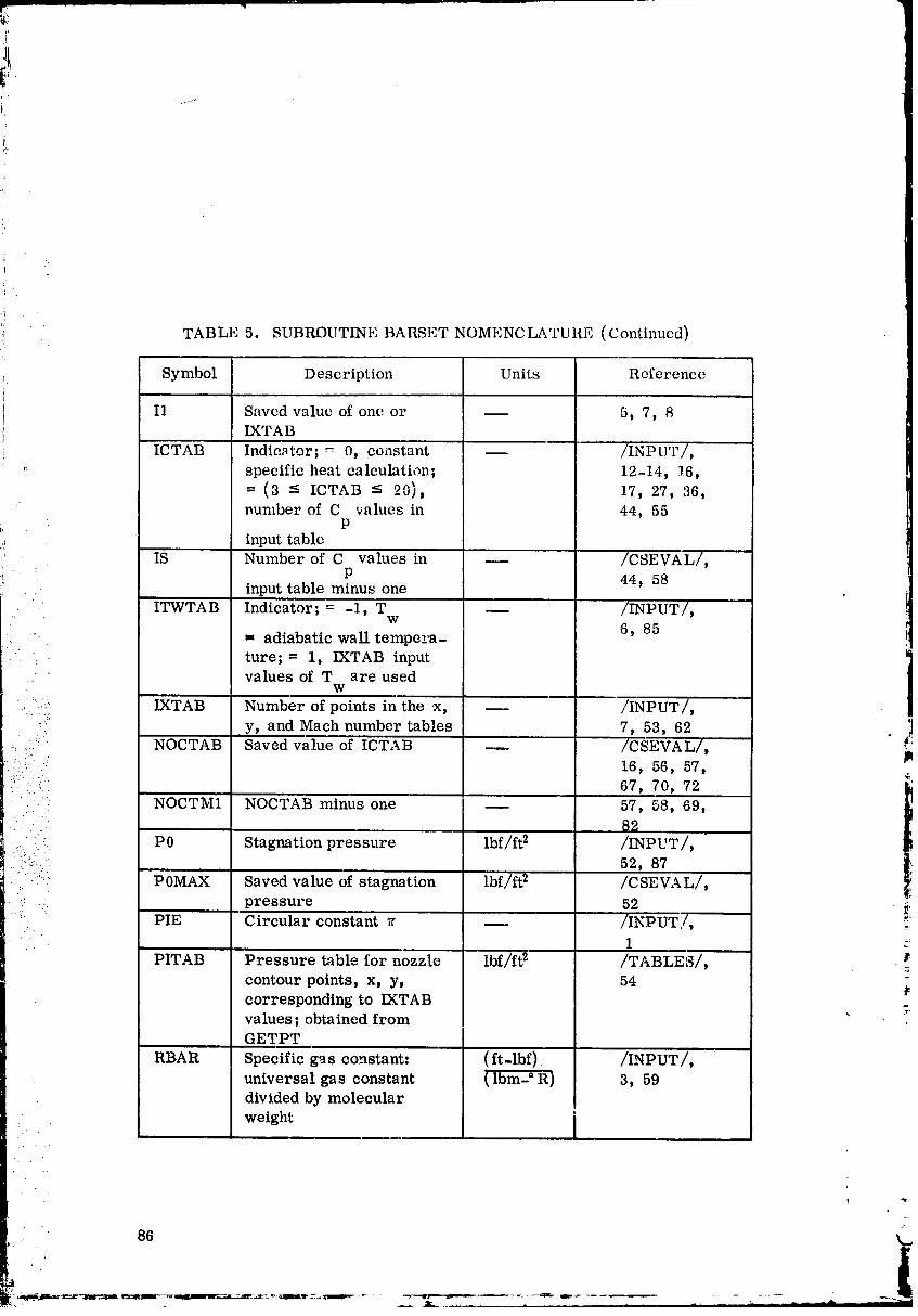
TABLE 5. SUBROUTINE BARSET NOMENCI__.TURE (Continued)
Symbol Description Units Reference
I1 Saved value of one or m 5, 7,IXTAB
ICTAB Indicator; _ 0, constant m /INPUT/,
'_ specific heat calculati,_.; 12-14, 16,= (3 -- ICTAB -- 20), 17, 27, 36,
' number of C values in 44, 55P
input table
IS Number of C values in -- /CSEVAL/,
" ' P 44, 58. input table minus one
ITWTAB Indicator; = -1, T m /INPUT/,'" W
• = adiabatic wall tempe__.a- 6, 85
" ture; = 1, IXTAB inputvalues of T are used
w
........:':_" IXTAB Number of points in the x, _ /INPUT/,• . . .!:
y, and Mach number tables 7, 53, 62 ]
.:....::' NOCTAB 'Saved value of ICTAB _ /CSEVAL/, _:i.-:S.::I"._. 16, 56, 57,
:::" '" 67, '70, 72.. " NOCTI_I1 NOCTAB minus one _ 57, 58, 69,
• 82" P 0 Stagnation pres sure Ibf/ft 2 /INPUT/,
::_:: _ 52, 87":' POMAX Saved value of stagnation lbf/ft 2 /CSEVAL/,
.: .... pressure 52 ._.• _" PIE Circular constant _ _ /INPUT/, _
1 :_
PITAB Pressure table for nozzle lbf/ft 2 /TABLE_/,
contour points, x, y, 54corresponding to IXTABvalues; obtained from " ;GETPT
RBAR Specific gas constant: (ft-lbf). /INPUT/,
universal gas constant (lbm-° R) 3, 59divided by molecular
• - weight '
O0000002-TSF01
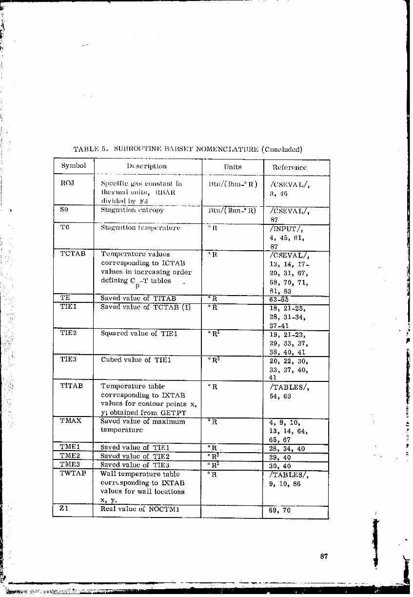
'!!
TABLE 5. S[JttROI!'['INI_ BAIISI,I NOMENCLATIIIIE (Concluded)
Symbol 1)cscription Units Reference
ROJ Spccdfic' gas constant ill Btu/( lbm-° R ) /CSI,VA L/,thcrnl:tl tlnil, s, IUI,\I{ 3, 46
divided liy I,'d,; S0 Singnation c.nl:roliy Btu/( lbm-° R) --7_,----
87
TO Stagl]atioll tcnlllcr;ittlro ° I1. /INPUT/,
;{ 4, 45, 61,? 87
i' . T(J'TAB Temperature wtlues ° R /CSEVAL/,
', corresponding to ICTAB 13, 14, 17-i: : values in increasing order 20, 31, 67,
defining C -T tables 68, 70, 71,
r. • P 81, 83_ 'rE "l Saved value of TITAB _R 63-65
TIE1 Saved value of TCTAB (I} °R 18, 21-25,
' 28, 31-34,37-41
TIE2 Squared value of TIE1 ° R2 19, 21-23, #':', 29, 33, 37,• -...-
"." " 38, 40, 41"" TIE3 Cubed vahle of TIEi °R 3 20, 22, 30,
33, 37, 40,41
"."L:_ TITAB Temperature table ° R /TABLES/,corresponding to IXTAB 54, 63
•: values for contour points x, r_.. y; obtained from GETPT• TIVIAX Saved value of maximum °R 4, 9, I0, $
temperature 13, 14, 64,65, 67' i,
TMEI Saved valueof _?IEI °R, 28, 34, 40 -_TME2 Saved value of TIE2 °R 2 29, 40TME3 Saved vahte of "T.IE3 ° R 3 30, 40
TWTAB Wall temperature table ° R /TABLES/,
corresponding to IXTAB 9, 10, 86values for wall locations
x, y.
Z1 Real value of NOCTM1 69_ 70 .
87 Iw
°,
00000002-TSF02
!
r¸
SUBROUTINE BMFITS
Subroutine BMFITS computes the coefficients from a cubic splint
fit routine using t,_blulnr data.
COMMON BLOCKS
,. No COMMON blocks are used.
TBL SUBROUTINES
Subroutine BARSET calls BMFITS.
: BMFITS does not call any TBL subroutines.
FORTRAN SYSTEM ROUTINES
i No FORTRAN library routines or built-in FORTRAN functions are
used.
• CAI,LING SEQUENCE• ..(
:_:.... The subroutine calling sequence is l_
1
:"..". CALL BMFITS (X, Y, N_ BL, CL, DL)"- ,:.
• where
!:i iilI. ": :¢ X = array of independent table values,[- .:.
• Y = array of dependent table values, _
N = number of values in the X and Y arrays,
BL = array of coefficients for first-power term,
CL = array of coefficients for second-power term,
DL = array of coefficients for third-power term.
88
k
00000002-TSF03
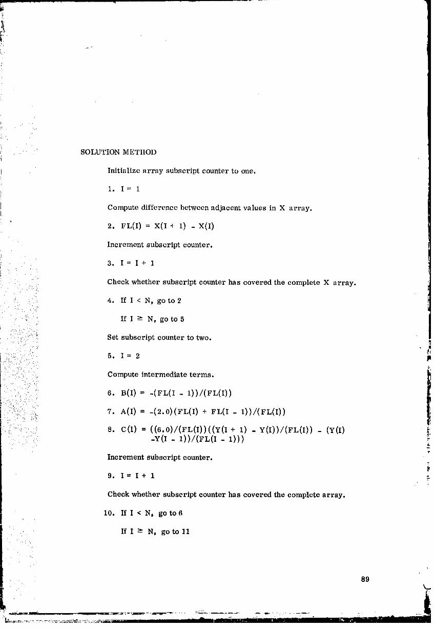
i)
SOLUTION METHOD
Initialize array subscript counter to one.
1. I= 1
Compute difference between adjacent values in X array.
m
2. L(I) -- x(I - x(I)
Increment subscript counter.
3. I = I+ 1, • . : .
: . Check whether subscript counter has covered the complete X array.
_ : 4. If I < N, go to2
: -... •.
• ' -": If I >- N, go to5
; :_!!ii:i ::? Set subscript counter to two.m
,:..... i':_ _,.?.... ..., .."
i:_:.i_:i'L:ii:'i:':!i: ;?:i,,. Compute intermediate terms. 1
.:._.:-. 6. B(I)= -(FL(I- 1))/(FL(I))
,_. .... :,. 7. A(I)= -(2.0)(FL(I) + FL(I - 1))/(FL(i))
_II'I :: 8. C(I) = ((6.0)/(FL(I))((Y(I + 1) - Y(I))/(FL(I)) - (Y(I) !::: : ::: :i: -Y(I - 1))/(FL(I - 1))) _.
t"
Increment subscript counter.
(,
9. I=I+l
Check whether subscriptcounterhas covered the complete array.
10. If I < N, goto6
:.." If I _ N, go toll
89
I" _....3L - _-.- -___3r:--_- _Jm_im,._ _- - _ ..... ._ _ . - : ....... _
00000002-TSF04
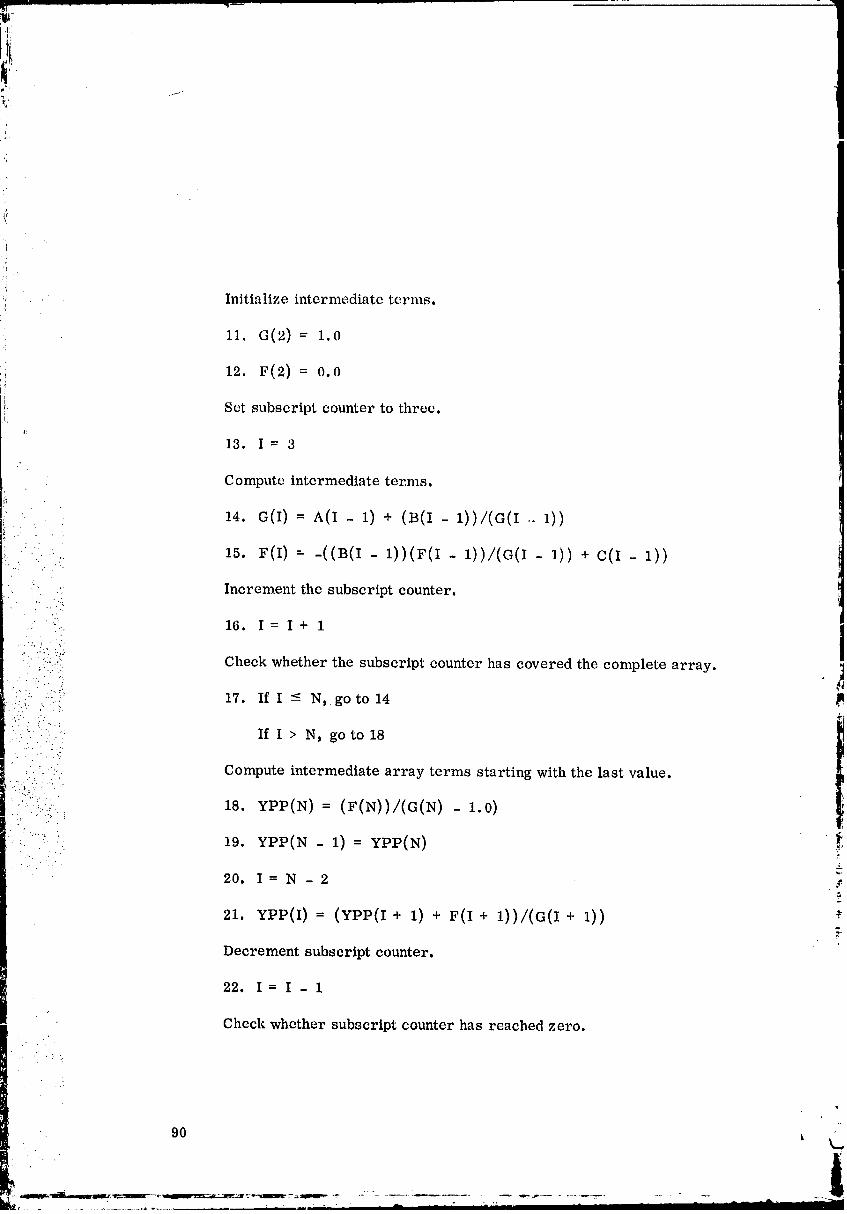
,i
'!i:!
,{_; Initialize intermediate terms.
.i'f
::! 11. G(2) = 1.0
},12. = o.o
t, Set subscript counter to three.
#:
13, I=3
Compute intermediate ter, ms.
14. G(I) = A(I- 1) + (B(I - 1))/(G(I .. 1))
15. F(I) = -((B(I- 1))(F(I- 1))/(G(I- I)) + C(I- 1))... : .
Increment the subscriptcounter.i.- :j: : "._
"".. 16. I= I+ i
:!J":::': Check whether the subscript counter has covered the complete array.• ;-.:.:.
• .......
':": ""! 17. If I -< N,.go to 14 II
-'.:. i.-"..
• If I > N, go to 18• ' • - "L•
::....,.:.ijj _.jj Compute intermediate array terms starting with the last value.
• :,._:.._... 18. YPP(N) = (F(N))/(G(N) - 1.0)
: _._'i_". 19. YPP(N - i)= YPP(N)
. .• . .•
20. I=N-2
21. YPP(I) ; (YPP(I + i) + F(I + l))/(O(I + i))
Decrement subscript counter.
22. I=I-1
' Check whether subscript counter has reached zero.
.' . • .
- 90 _ k.
l
,,,,,_,_ ..,,-._.m=----,,......=' - :_-=-"_ - ...... - - ' I
....... ..... . ...... _,, " ' , i - - " _ I I I
O0000002-TSF05
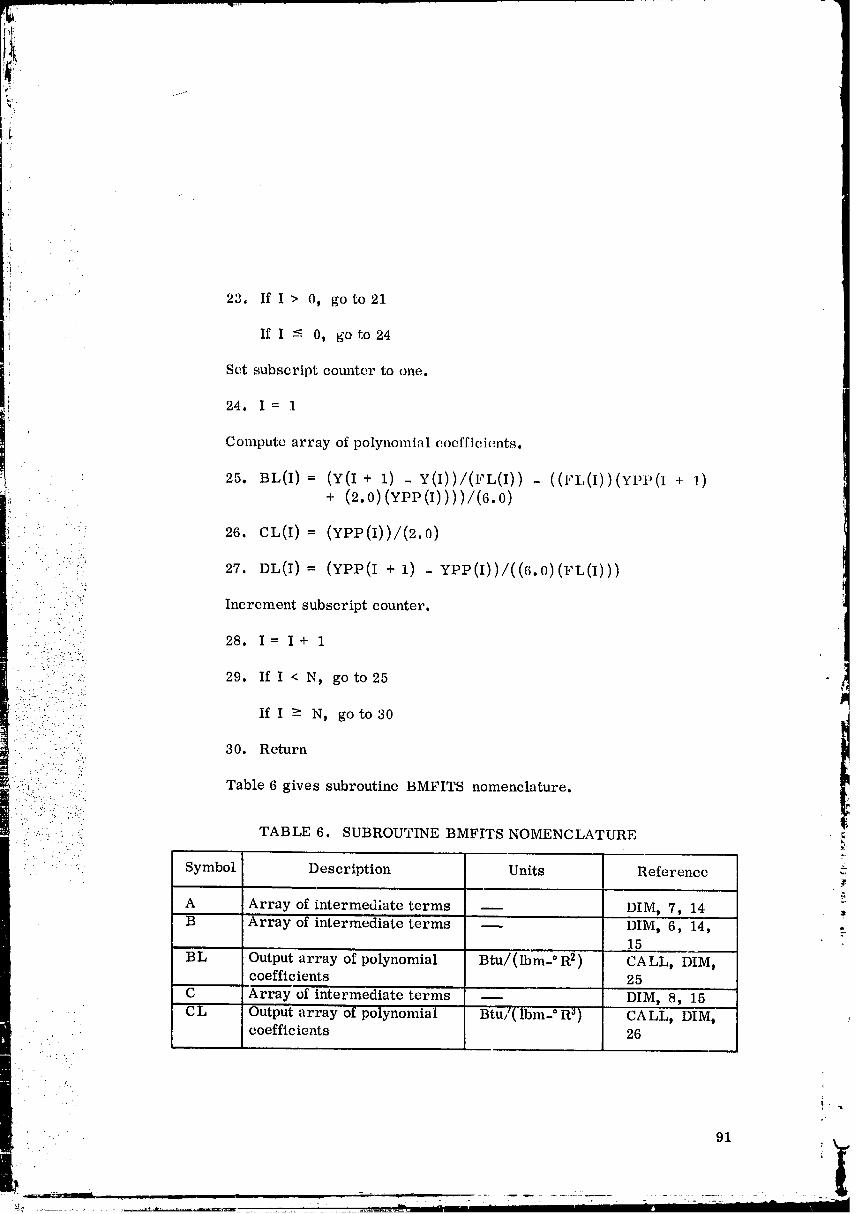
-- ..q
).
.!
'i 23. IfI > 0_ go to 21
If I <- 0, go to 24
Set subscript counter to one.
24. I=1
Compute array of polynomial coefficients.
25. BL(I)= (Y(I + 1) - Y(I))/(FL(I)) - ((FL(I))(YPP(I -_ 1)•.. + (2.0) (YPP (I))) )/(6.0)
': 26. CL(I)= (YPP(I))/(2.0)
:):/ 27. DL(I)= (YPP(I + 1) - YPP(I))/((6.0)(FL(I)))
:: " . ":_; Increment subscript counter.
_.:. 28. I= I+ 1• -'-.i:._.-}-
.....= '.::::..::..(.:. 29. If I < N, go to 25 ti...... . : '.i-:"" If I > N, go to 30. . . .. - .
!
"--- :) :- 30. Return. -' .'".
:-_. " " . Table 6 gives subroutine BMFITS nomenclature.•- . _ . - . ." '
"-:...._
: :}::;: ::;::.- . -.
-.:...... . ...!. TABLE 6. SUBROUTINE BMFITS NOMENCLATURE i.
• - Symbol Description Units Reference
A Array of intermediate terms DIM, 7, 14B Array of intermediateterms _ DIM, 6, 14, .
15
BL Output array of polynomial Btu/(lbm- ° R 2) CALL, DIM,coefficients 25
C Array of intermediate terms _ DIM, 8, 15
CL Output array of polynomial Btu/(lbm- ° R _) CALL, DIM, .coefficients 26
: . ..' .
. " 91
00000002-TSF06
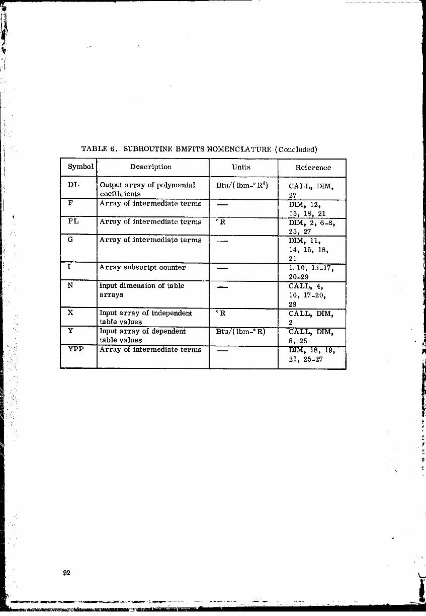
it
i '
_ :' TABLE 6. SUBROUTINE BMFITS NOMENCLATURE (Concluded)rl
i Symbol Description Units Reference
i DT. Output array of polynomial Btu/( Ibm- ° R 4) CALL, DIM,coefficients 27
F Array of intermediate terms -- DIM, 12,
,, .. 15, 18, 21FL Array of intermediate terms °R DIM, 2, 6-8,
... 25, 27G Array of.intermediate terms -- DIM, 11,
I, 14, 15, 18,21
I Array subscript counter 1-10, 13-17,20-29
N Input dimension of table m CALL, 4,arrays 10, 1'/-20,
29
., X Input array of independent °R CALL, DIM,...._ table values 2
Y Input array of dependent Btu/( Ibm- ° R) CALL, DIM,table values 8, 25
:i"i: YPP Array of intermediate terms m DIM, 18, 19, ":::.. 21, 25-27
.-.-.
'i
t
O0000002-TSF07
SUBROUTINE DIRECT
Subroutine DIRECT controls the overall flow of the program. It calls
subroutines which successively read in data, compute program constants, fitcurves, and then obtain the boundary layer solution.
COM MON BIX)CKS
N_ COMMON blocks are used.
'] " l"TBL SI BllOI 1INI,;S
•' Subroutines MAINTB and QUITS call DIRECT,
DIRECT calls BARCON, BARSET_ and READIN.
.: FORTRAN SYSTEh ROUTINES
No FORTRAN library routines or built-in FORTRAN functions are...... , used.
-...
""'-..'- CALLING SEQUFNCE.-.. ..
i'--!:_:_7:.:'::
:. ;.:.:::o The subroutine calling sequence is: CALL DIRECT..: ...-."
"" - Call subroutine to read input data.
• .:.....': i:...: ._
::..:...::<.;7. 1. CALL READIN'" .-!._'__
•. I,. " %
" Call subroutine to compute constants and initialize data.
.... 2. CALL BARSET
Obtain the boundary layer solution .
3. CALL BARCON
Read in the next case.
4. Gotol
9a
00000002-TSF08
_; SUBROUTINE CFEVA L.:!
Subroutine CFEVAI, evaluates the skin frtctio_ coefficient Cf as at
function of Cf R(_ based on Colts' relationship. For wflues of Cf R_ such
that 0 < C[ 1l_ < 2,51, Cf is ewlluated from
0. 009896
ct.= (g •• .. -. f
.... For values of 17,fR_, such that 2.51 -< Cf R_ < 1982759.2, Cf is
" .: evaluated from a cubic spline fit of log (_f) versus log (gf R_')c, from input t
• " data. All other values of _f _ _ are considered out of range. !
F
: !COMMON BLOCKS
:_: No COMMON blocks a_e used.
::t:., TBL SUBROUTINES
, .... Subroutines BARPRO and START call CFEVAL.'!" :L.: .:-:' |
i:.:.!.,_:., " CFEVA L calls subroutine QUITS.>".'. ......
: ' FORTRAN SYSTEM ROUTINES. . . :...,
_..., FORTRAN library routines A LOG and EXP are used.:: .:'.. ".:._..:':: .... No built-in FORTRAN functions are used
.....
: " :':. CALLING SEQUENCE .t
_. ...._ CFEVAL is a function routine and is called as:• . .. .
CFBAR= CFEVAL (CFRT),
where CFRT is the skin friction coefficient multiplied by the Reynoldsnumber based on the momentum thickness, and CFBAR is the skinfriction coefficient.
SOLUTION METHOD
Save _f _ = (CFRT).
1. Z = CFRT
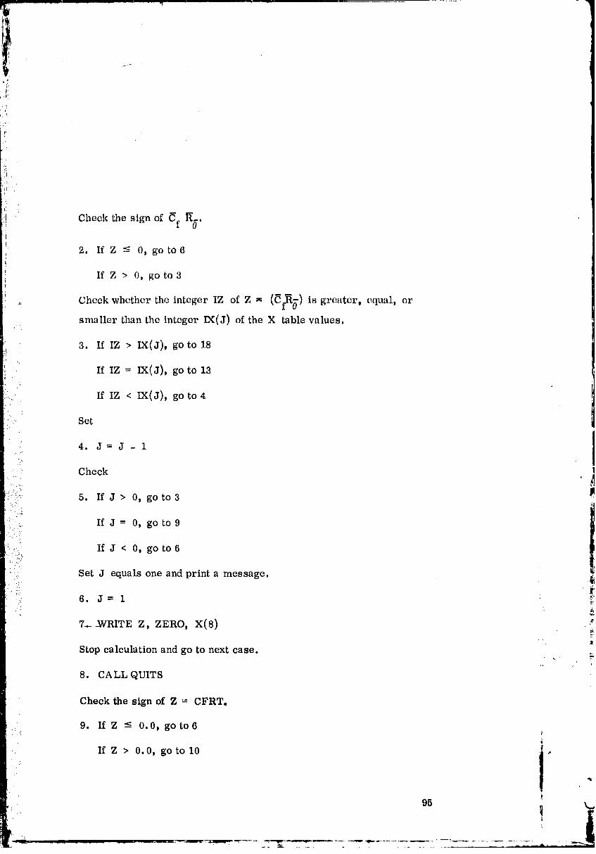
iTM!_ m m
Check the sign of Cf R_.!i
t 2. If Z -': 0, go to6
If Z > 0, go to3
Check whether the integer IZ of Z _ (_f_) is greater, equal, orJl
smaller than the integer IX(J) of the X table values.
3. If IZ > IX(J), go to 18
If IZ = IX(J), go to 13
If IZ < IX(J), go to 4
Set
4. J=J-i
Checki
•
i::::!_ 5. If J > O, go to3P
. If J = 0, go to 9
_ If J < 0, go to6• . -":
•: Set J equals one and print a message.
• , ...- 6. J=l£
:¢7..__WRITE Z, ZERO, X(8) ,
Stop calculation and go to next case.
8. CALL QUITS
Check the sign of Z = CFRTo
9. If Z - 0.0, go to6
If Z > 0.0, go to 10
O0000002-TSFIO
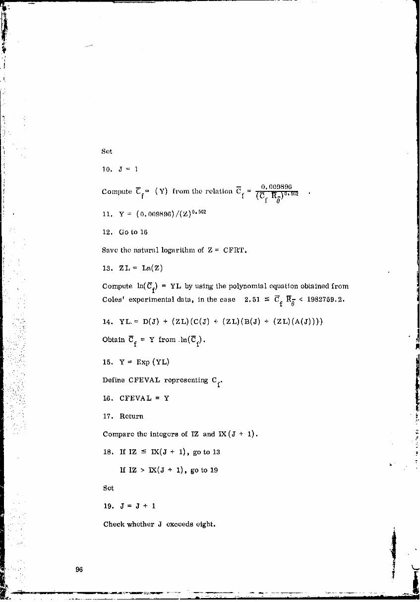
:! Set
10. J= 1
I O. 009896
Compute _'f= (Y) from the relation _f = (_f 1T0.),,.._,;2 .
,: 11. Y= (0.009896)/(Z) °'562
' 12. Go to 16
,1 Save the natural logarithm of Z = CFRT.t'
71 13. ZL= Ln(Z)
; Compute ln(_f) = YL By using the polynomial equation obtained from
.... Coles' experimental data, in the ease 2.51 -< gf g_- < 1982'/59.2.
.:='/'_ 14. YL.= D(J) + (ZL)(C(J) + (ZL)(B(J) + (ZL)(A(5)))):_.:
.. ..
'(.: .i Obtain _f = Y from.ln(_f).
" ;.-":' 15. Y = Exp (YL)
1
• .." ..
• .. Define CFEVAL representing Cf.' .:... .
:.: .,.,. ].6. CFEVAL = Y
-. 17. Return _,
z_
Compare the integers of IZ and IX (J + 1). :_
18. If IZ -< IX(J + 1), go to 13 •
If IZ > .IX(J + 1), go to 19
Set
19. J= J+ 1
.. - Check whether J exceeds eight,
96- :.: ..
O0000002-TS F11
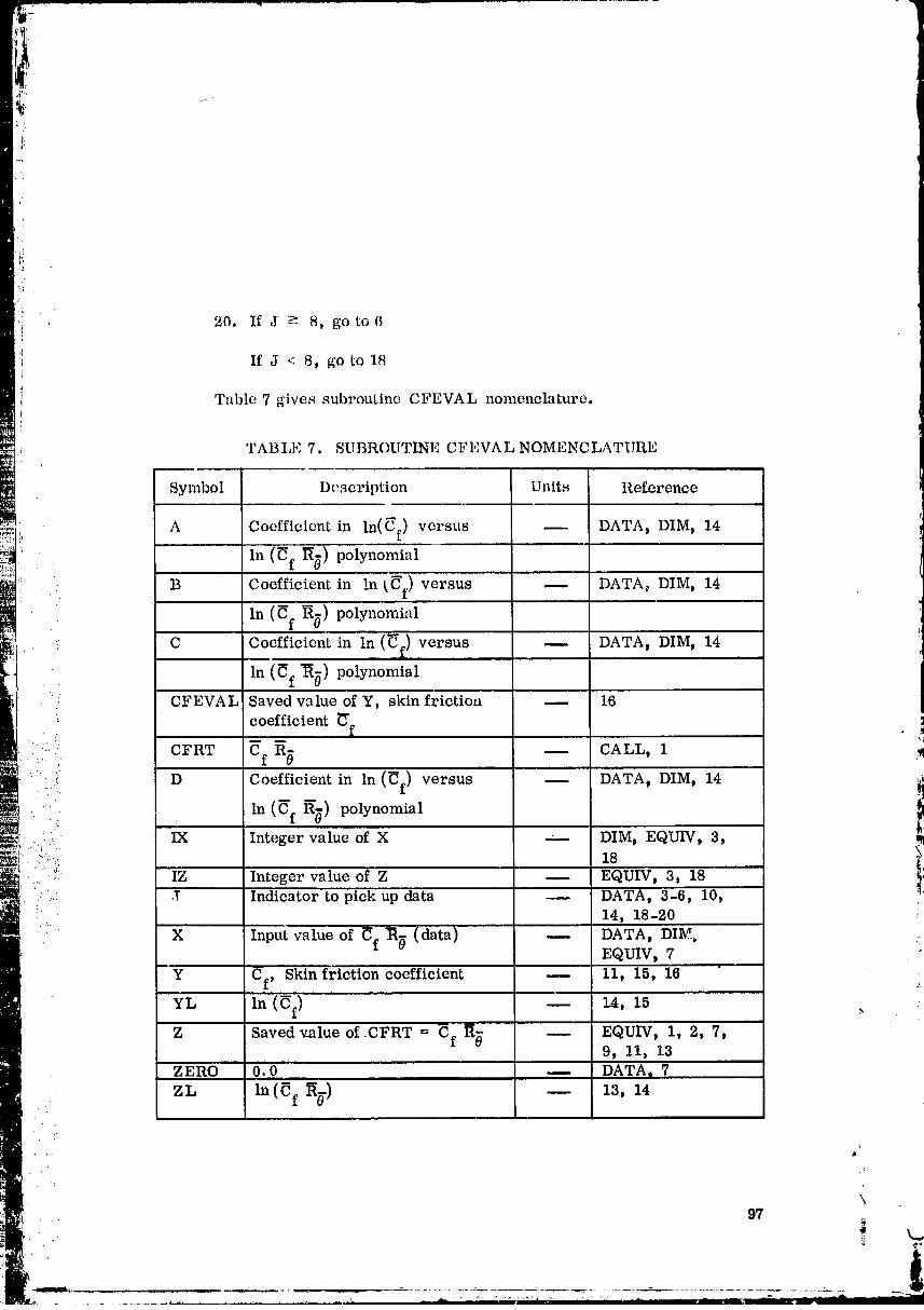
'i 20. If J -_ 8, go to6
:Li If J < 8p go to 18l
i Table 7 gives subroutine CFEVAL nomenclature.
TABLE 7. SUBROUTINE CFEVAL NOMENCLATURE
Symbol Description Units Regm, ence
A Coefficient tn ln(_f) versus DATA t DIM t 14i,
; In (_f r_g) polynomial
B Coefficient in In (C'f) versus DATA_ DIM, 14
In (Cf _) polynomial
.. C Coefficient in In (_) versus DATA, DIM, 14
In (_f "_) polynomial. _
. :, CFEVAL Saved value of Y, skin frictioa -- 16
coefficient _'f
: :.:. CFRT gf Rg.:: .. -- CA LLI 1 ..,I
:"""..- .'"::,':_ D Coefficientln(% %) inpolynomialln(_f) versus -- DATA t DIM t 14 'i'
_.=_,.. IX Integer value of X --- DIM,18EQUIV, 3, !_'-: "'/: IZ Integer value of Z -- EQUIV, 3, 18
.: ._: ,T Indicator to pick up data -- DATA, 3-6, 10,! 14, 18-20
'- X Input value of _f _ (data) -- DATA, DIM, ,:EQUIVt 7
-- Y Cf, Skin friction coefficient 11, 15, 16
YL In (Cf) 14, 15 ., :
Z Saved value of.CFRT = Cf g_ EQUIV, 1, 2, 7,9_ 11, 13
ZERO 0.0 -- DATA t 7
• ZL In (_f l_g) -- 13, 14
• . t'
\.97
k..,• 'i. " _.
O0000002-TSF13

SUBROUTINE FIIF
_: Subroutine FIIF defines the function (of S) to be evaluated by the
numerical integration routine INTZET. Three second-degree coefficients
(AF,B F , C F) and an exponentvalue n are determined by subroutine ZETAIT.
Enthalpy value h is comouted from
h=H + o ww _ S + S2
= A F + B F S + C F S2 .
(AFINT) (BFINT) (CFINT)
Entering subroutine SEVAL with h, the temperature _ is obtained.The appropriate form of the function is then evaluated for
::_ IFINT = 1, f(s)= (T_)sh (t- S)... FIIF (S)
•- and p
" IFINT = 2, f(s) = ... FIIF (S) ,
: ' where T /_" has been used for g/pe • .•._'t e
"':'" COMMON BLOCKS
COMMON block COFIIEAs used. . _.
TBL SUBROUTINES _:
Subroutine INTZET calls FIIF.
FHF calls SEVAL.
FORTFtAN SYSTEM ROUTINES
: No FORTRAN library routines or built-in FORTRAN functions areused.
•. i98 _J
00000002-TSG01
!!s._L
)
CALLING SEQUENCE
FIIF is a function routine and is called as
Y = FIIF(S),
where S is an independent variable 0 - S -< i and defined as
S=s=_ =
or
' ' h - H 1/n. oS= W= _ H -H \_.._/ "-: 0 W
FIIF (s) represents
' / " t
• :' T T
...: esn esn--" (i-s) or_ .'/ t " •
:::: " SOLUTION METHOD P
• . Initialize power summation term to i.0.
.:'..
":-...:'.:i" i. STO M = i.0
• ., Cheek the sign of power index n used in the velocity and enthalpy•:. distribution equations. MMINT = (n) is defined in subroutine ZETAIT.
2. If MMINT ---0, go to 5 ,,,r
If M MINT > 0, go to 3
Save ':Sn''as STOM.
3. Do 4, I = l, MMINT
t
99
00000002-TSG02
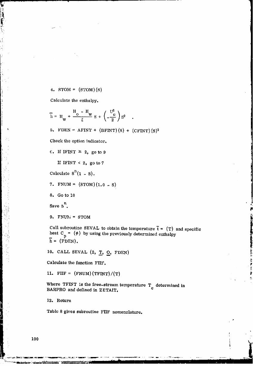
_i 4. STOM = (STOM)(S)ij
Calculate the enthalpy.
i _ H - H /i h = H + o Ws+ _ S2
w _
': 5. FDEN = AFINT + (BFINT)(S) + (CFINT)(S) 2
Check the optionindicator.
£,. If IFINT -_ 2, go to9
: If IFINT < 2, go to7 f
Calculate S n(1 - S). I
7. FNUM = (STOM)(1.0 - S)
8. Go to 10
,_, Save S . /
9. FNUhi = STOM
CaR subroutine SEVAL to obtain the temperature _ = (T) and specific
• heat C = (_b) by using the previously determined enthalpy..... P
:: _ = (FDEN).
_ 10. CALL SEVAL (2, T_,O, FDEN)
Calculatethe functionFIIF.
II. FIIF = (FNUM)(TFINT)/(T)
Where TFINT is the free-stream temperature T determined ineBARPRO and defined in ZETAIT.
12. Return
Table 8 gives subroutine FIIF nomenclature.
100 \
00000002-TSG03
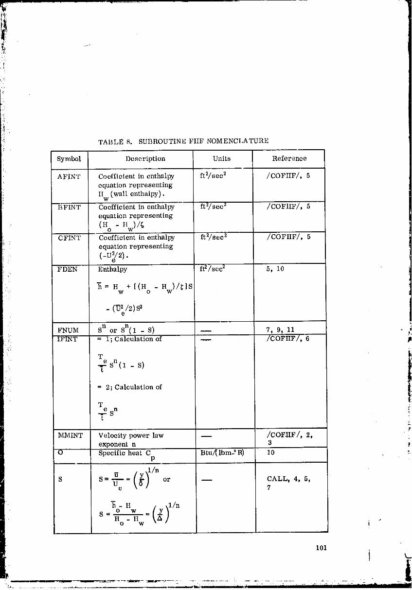
ii' TABLE 8. SUBROUTINE FIIF NOMENCLATURE
Symbol Description Units Reference
AFINT Coefficient in enthalpy ft2/sec 2 /COFIIF/, 5
equation representing
Hw (wall enthalpy).
BFINT Coefficient in enthalpy ft2/sec 2 /COFIIF/, 5
equation representing
(H o - Hw)/_
CFINT Coefficient in enthalpy ft2/sec 2 /COFIIF/, 5
equation representing
--.... (-U_e/2).FDEN Enthalpy ft2/sec 2 5, 10
Z= H +[(H -H )/_]Sw o w
_ (_'e/2)S'
FNUM Sn or Sn(l - S) -- 7, 9, ii ._," IFINT = 1; Calculation of -- /COFIIF/, 6
Te Sn"V (1 - s)
: = 2; Calculation of
T _:e n-_-=S _:t
MMINT Velocity power law -- /COFIIF/, 2, :exponent n 3
O Specific heat C Btu/(lbm21_) 10 :.P
S S= ,-7--= -- or -- CALL, 4, 5,e 7
-6- H )I/ns=O w =(_H -H ,,o w
101
00000002-TSG04
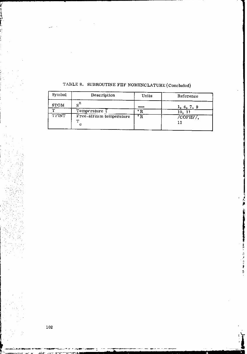
TABLE 8. SUBROUTINE FIIF NOMENCLATURE (Concluded)
i . ' .
i Symbol Description Units Referencei
STOM Sn -- 1_ 4, 7, 9i --T Temperature _" ° R 10, 11
"TFINT Free-stream temperature _ R /COFIIF/,T 11
e
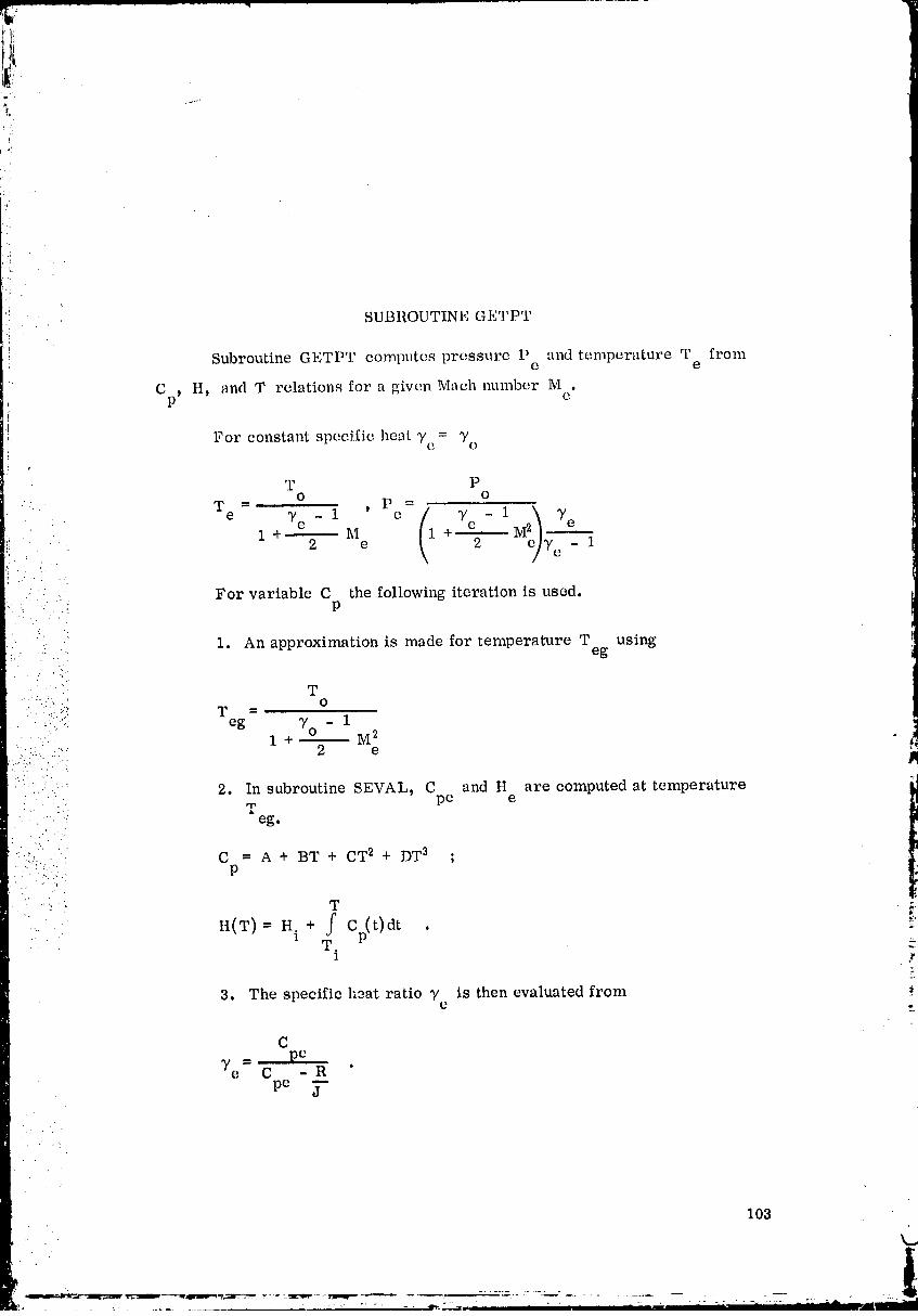
t; ¸
!:i
!!i . . ' SUBROUTINE GETPT}; .
Subroutine GETPT computes pressure P and temperature T from@ e
Op, H, and T relations for a given Math munber M .O!i:
For constant specific heat y e = "/oa,
T PO O
• Te - Yc 1 ' P =(1 Ye - 1 e)
- c y e
1 1_I + M2 --" e 2 _/e - 1
: :- For variable C the following iteration is used.m
• ::: -. 1. An approximation is made for temperature T using,.. eg
2:
• T".:" ' O
%;;. -eg 3,0 - 1• ': 1 + _ M 2
? !._.... ' 2 e-..._.- . -._. pm
• .::. 2. In subroutine SEVAL, C and H are computed at temperature,T, pe e
" --. ' . 2. .a
eg.
.:....:. . :
.:-.:;.... C = A + BT + CT 2 + DT a ;P
H(T) = H. + C t dt . _:1T _.
1 r
3. The specific h3at ratio _/ is then evaluated frome
C= pe
Ye C - R 'pe j
103
00000002-TSG06
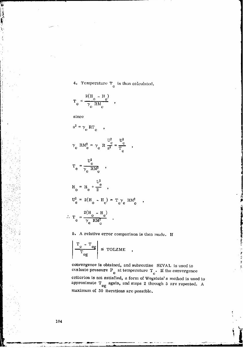
4. Temperature T is th_ calculated.e
2(H° -T = )
e Te RM e
since
r
a2 = Te RT ,e
U2 U2
Te RM2 = "/e R e=mee _ T '. . e
! .._ ., U2: - • e
T -" • e Te _ '• " e
.. U2.:.'" e
..........-:. H = H +o e 2 '
:"::L...::""." U2 = 2(H - He) = TeY e RM 2..::..'.- ." ' . .: e 0 e )
• ..'::" . 2(H' ," ' T - o - He-
)
• .. ,.:. e _'YeRMZ '
I .:!:i._.,.::' ::,:::" -: e-"-:""-"-:: 5. A relative error comparison is then made. If
• '-: .. :. • - .
_'. :. ': T - T
-;-. . e eg -< TOLZME• " W )
eg
convergence is obtained, and subroutine SEVAL is used toevaluate pressure P at temperature T . If the convergence
e e
criterion is not satisfied, a form of Wegstein' s method is used to
approximate T again) and steps 2 through 5 are repeated. Aeg
maximum of 50 iterations are possible.
J
104
• '• i11
00000002-TSG07
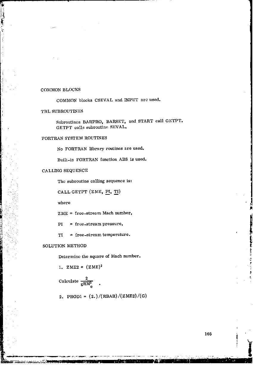
,i "
• ' COMMON BLOCKS
COMMON blocks CSEVAL and INPUT are used.i
TBL SUBROUTINESl
SubroutinesBARPRO, BARSET, and START callGETPT.GETPT callssubroutineSEVAL.
FORTRAN SYST EM ROUTINES
No FORTRAN library routines are used.
. Built-in FORTRAN function ABS is used.
CALLING SEQUENCE
The subroutine calling sequence is:
"'.::::-. CALL GETPT (ZME, PI, TI)
:::.- where:" .4..:"..
.-. " ZME = free-stream Mach number,
•. " PI = free-stream pressure,
: .::i_!::i:.( WI = free-stream temperature.
"" SOLUTION METHODr "? '
ii:. :i Determine the square of Maeh number. ;-
i. ZME2 = (ZME) 2 _:.
2 -._
Calculate _ .e
2. PROm= (2.)/(RBAR)/(ZME2)/(Q)
105 i
:iT
00000002-TSG08
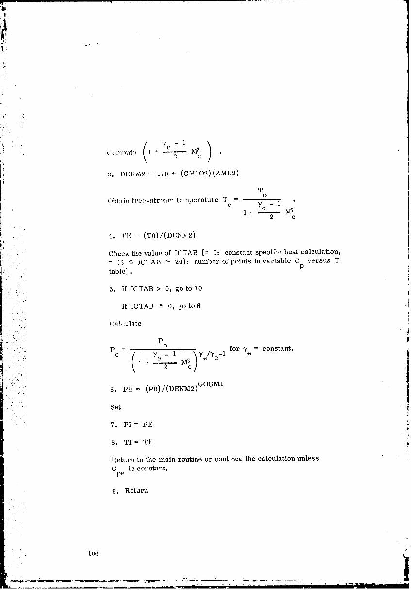
.._o
:i
Li::r
i'i
:i
•. (_oml_Ute 1 + , •
i
3. 1}ENM2 = 1.0 + (GM102)(ZME2)
TO
Ot)i:ain free-strem_ temperature T =• e yo - 1 "
• " 1 +-------- M22 e
4. TE= (T0)/(DENM2)
- Cheek the value of ICTAB [= 0" constant specific heat calculation,
= (',3 _ ICTAB _ 20)" number of points in variable C versus T•" table]. P
::i" :_:.. 5. If ICTAB > 0, go to 10
" If ICTAB - 0t go to6
"1"-:ii:i! Calculate ,""
::::..'.., P = o for 7 e = constant.
..-" e ( Ye - 1 )Ye/Te-lM_
. ...:. _,_
1+ 2 e
_ii_"::"".: 6. PE = (P0)/(DENM2) GOGM1::. -" %
i::(: set
7. PI=PE
8. TI = TE
Return to the main routine or continue the calculation unlessC is constant.
pe
9. Return
106 __
00000002-TSG09

• Set the iteration counter to zero initially.
10. ITER = 0
l)efine the tolerance.
11. TEL----(TOI, ZME)/(ZME)
Save the previovs approximation of free-stream temperature Teg.
12. TEe = TEG
: .. 2(ii° - Hc)" Save T = as calculated in step 17.
c YeRM2e• .- . .'
•"...!.:.
.':. ,-: 13. TCO = TC
•: ..-... Approximate Teg.
' :_:."::.:" 14. TEG = TE
;i"::i..: '::' ;:? Call subroutine SEVAL to obtain C and H for the known T ._-:>. ,,:::..: De e e
.... -: .4:.
:'.:%::.:- 15. CALL SEVAL(lt TE_ CPEt HE)
: :i!::_: :i: Calculate specific heat ratio _/e"
_ " 16, GAME = fCPE)/(CPE - ROJ)
.,....... (H° )_. .: :.. 2 -H• ...:- e
-... . Calculate new free-stream temperature T =•.- . - e _eRM z "e
17_--_:EC = (H0 - HE)(PROD1)/(GAME) "=
Test whether the temperature falls within the tolerance.
18. If I(TC - TE)/(TE)I <-- TeL, go to 33
If I(TC -TE)/(TE)I > TeL, go to 19
::... .' .
• .:' . : ".
• • .il
107
i i
00000002-TSG10

I
';i Check on the number of iterations.
19. If ITER > 0, go to 22
I_ If ITER --_0, go to 20I
I Determine
20. TE = ((2.0)(TE)+ TC)/(3.0)
21. Go to 30
Check on the number of iterations, and print out the e,.ror messageif convergence was not obtained within 50 iterations.
22. If ITER -< 50, go to 25
: If ITER > 50, go to 23
..... i Print out error message." "::_i
:.i._.:': 23. WRITE ZME, TC, TCO, TE, TEO.. ,._.. ..
:.:.:...::..: 24. Go to 33" .' ..
. . -.._
• • Use a form of Westein's method to approximate a new value for T .•. .: • e
:: .:./ :. _...; 25. ZK = (TC - TCO)/(WE - TEO)
:'-.... •..,
; 'ii' " 26. TE = (TC - (ZK)(TE))/(1.0 - ZK)_.
• Check whether convergence has been achieved.
27.-If I(TE - TEG)/(TE)I < TOL, go to 32
If I(TE - TEG)/(TE)I _- TOL, go to 28
Check on the number of iterations.
28. If ITER < 10, go to 30
• ." If ITER _ 10, go to 29
Check whether the calculated number falls within the tolerance.
108'

, 29. If I(i ', - TI.:O)/(TI':)I < TOL, go to 32.",i
:I _f I ('rl,:- 'm,,o)/(T,:)l ->TOI,,goto a0
Add one to the iterntion counter.
"tq[, :;30. 11 ',R I'i'l,;I{ + 1
' llepeat the above method until a convergence is obtained.
31. Go to 12
l)eterminethe new free-stream temperature.
32. TE: (TE+ 'rEG)/(2.0)
Call subroutine SEVAL to obtain the free-stream pressure P ,e
.. using temperature T and stagnation entropy S .• e O
..... '" 33. CALLSFVAL (-1, TE, PE, SO)• .. ".. • _
(:/..-
• :'(; 34. Go to7'.,.. ...
:-. -.. " Table 9 gives subroutine GETPT nomenclature. :,i,.... ..
.. • :.'..
"' ", ".]' TABLE 9. SUBROUTINE GETPT NOMENCLATURE
' 'i;}i.i!!i.ii. Symbol Description Units Reference i
i .
. }!":, .. CPE Specific heat at con- Btu/(lbm-°R) 15, 16_. - - " stant pressure in ..
free-stream C dpe
"i
7e - 1 'DENM2 1 + M 2 -- 3, 4, 6
2 e
G Accelerationof (lbm/Ibf)/(ft/sec2) /INPUT/, 2
gravityused as aproportionalityconstant "
109
00000002-TSG13

TG ....
!i
,_ • _ Ir , _ _ ,, • _,. Gt/I t I2ABLL 9 SUI ROt. IlNI', NOMENCLATUIII'_ (Continued)
Symbol Description Units Reference
GAME Specific heat rai:to _ 16, 1'1in free strean]
GM102 Ye - 1 _ /CSI,]VAL/, 3I:
2
: GOGM1 _/e /CSLVAL/, 6
. 1,e - 1• . , J.
_ : '! i... H0 Stagnation enthalpy ft2/sec 2 /CSEVAL/,•"' tt 17
• 0 , ,,,
::...."i:.. HE Free-stream ft2/sec 2 15, 17
/ :.)% enthalpy H' '"': e
- . :t.. . _
......:,.:: .i:_i ICTAB Indicator; =- 0, con- _ /INPUT/, 5
"" i!i_"::/!i!:: stant specific heat !1
• :;::: ca lcula tion; t:•
::":::::- ,.::_:"_""_" = (3 <- ICTAB <- 20),:"/::::::::":=":_:L dimension of variable
41
:.::.:".. "::.:.! .:',.
c versusT tableP' " ":[( ITER Iter'ation Counter _. 10, 19, 22,. , • .' . .... ,
"":'_": : ' P-0 Stagnation___pressure lbf/ft 2 ' ' /INPUT/, 6
:. :"".".i)::... PE Free-stream lbf/ft 'z 6, 7;" 33 :_
•-":.::::.. pressure P- e
PI ,Saved value of PE Ibf/ft 2 CALL,7
PROD1 2 ( ° R-see 2)/ft 2 2, 17 :
e
RBAR Specific gas con- (ft-lb)/( Ibm-" R) /INPUT/, 2" : stant: universal
• • gas constar_t
:.. divided by molec-
•::-' .: ular weight
- . .).": .:.
• .: C.
110
.°
• ........ - r
._-. ..-.-:.--. .-- . .-_, , • , i "m m l
00000003
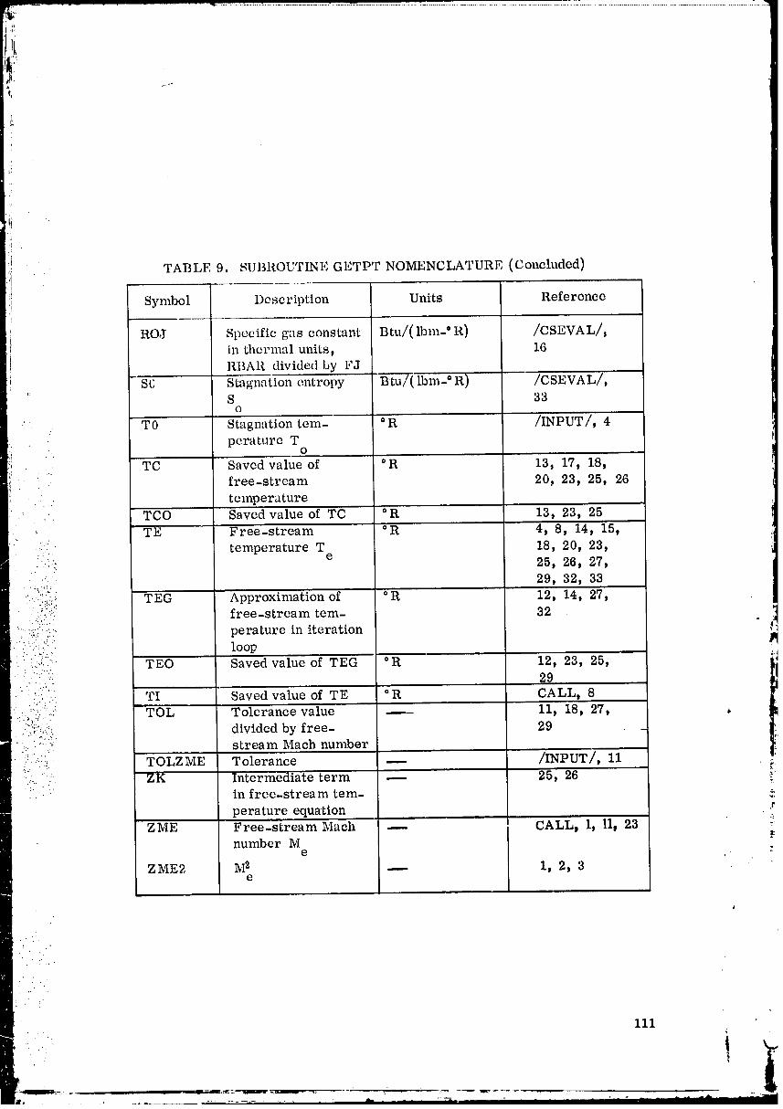
,(.
r
TABLE 9. SUBROUTINE GETPT NOMENCLATURE (Concluded)
Symbol Description Units Reference
ROJ Specific gas constant Btu/(lbm-" R) /CSEVAL/,
in thermal units, 16RBAR divided by FJ
SC Stagnation entropy B:tu/( lbm-° R) /CSEVAL/,S 33
O
-T0 Stagnation tem- °R /INPUT/, 4perature T
O
TC Saved value of °R i3, 17, 18,.... free-stream 20, 23, 25, 26
•..., temperature
•.' :'. TCO Saved value of TC °R 13, 23, 25•_ TE Free-stream °R 4, 8, 14, 15,
_. . ....3
-.::. temperature T 18, 20, 23,
• ..... 25, 26, 27,: '" 29, 32, 33
..".:il..!:!_!!_.:!);!i._ perature in iterationJ /.._'.:i: loop" "'"_''" TEO Saved value of TEG °R 12, 23, 25, _"• ....-:.._: 29
• - :_:i:!./::: TI Saved value of TE °R CALL, 8:-_-_::::..:: _ TOL Tolerance value' 11, 18, 27, ,
.-.;._-: divided by free- 29 __'_:_ stream Mach number
':-_.., " TOLZME Tolerance -- INPUT/, 11• _.: • .: . f
?i_ .. ZK Intermediate term 25, 26 _:in free-stream tem-perature equation
ZME Free-stream Mach -- CALLj 1, 11, 23 _number M
e
ZME2 M2 ---- I, 2, 3e
iii
• _
00000003-TSA03

..f
"F"
ii.'I
SUBROUTINE INTZ ET
Subroutine INTZET uses a numerical technique in connection with a
quintic spline fit to evaluate an integral within the limits X 1 = XC(1) andX2 = XC(21). The integration interval is divided into 20 coarse subintervals.
Since the integration limits are restrictcd to certain values (0, 1, _, 1/_), a
test on the interwd distance (X 2 - X1) is performed. If (X 2 - Xl) _ 0.1, thefunction is evaluated at 21 subinterval endpoints, and the integral is approxi-mated by the quintic technique with Siml2son's rule for the outer subintervals.
Eor (X 2 - XI) > 0.1 the maxilnum function value within the interval is deter-mincd, and an approximation of the integral is performed over the coarsesubintervals up to a point where the function value reaches 80 percent of the
, . . maximum value. Beyond this point the remaining coarse subintervals are, further subdivided individually into three fine subintervals. Solving the function
. . at the endpoints of the fine subintervals, the integral approximation is finally
completed using these finer subinterval step sizes..-
:.: -:-: For a given function f(S), evaluated at uqually spaced (AS) points
• ii So' Si' $2' $3' the quintic approximation of the integral is prepresentedby,. ,:..,., .
:::T.; 2AS
! f f(S)dS= -- [-f(s ) + 13f(s_)+ 13f(s2)- f(s3)] • ,_":-: :". 24 o "
"..-
• :'. , "'.-'....• .L ""
.... • . The one-sided Simpson rule is expressed by the following equation. • ": and diagram.
:._:,.:. " 1
:¢::::: f f(S)dS= _sIT[af(So)+ 8f(s,)-f(s2)]
"' i('
: _,y-
flS) ASi
• :"_" So' s, s_ s_ s
00000003-TSA04
I
:i COMMONnLOCKS
No COMMON blocks are used.
! TBL SUBROUT_ES
Subroutines START and ZETAIT call INTZET.|:
INTZET calls FIIF.
FORTRAN SYSTEM ROUTINES
. . No FORTRAN library routines are used.
:... . Built-in FORTRAN function FLOAT is used.
CALLING SEQUENCEA
The subroutine calling sequence is:
, CALLm¢ZET(Xl, X2, Zm___T):"::,
•.._.:.(. where
•..:!i:!i:,.:. Xl = lower limit of integration 1
:....-. X2 = upper limit of integration
.:.".::".: ZINT = integral value.
_. SOLUTION METHOD _,.'..
Set the length of interval for integral.
1. DX21 = X2 - Xl
Set the initial value of integral as zero,
2. SUMINT = 0.0
Check whether the interval length is zero.
3. If DX21 = 0.0, go to 22 _:
If DX21 ¢ 0.0, go to 4 t
00000003-TSA05
!J
_: Divide the interval over which the integration is performed into 20i coars e subintervals.J
4. DXC = (DX21)/(20.0)t
Set maxinmm value of integral and its subscript counter to largenegative values.
Jr
5. IMAX = -9999
6. FMAX = -1.0E30
. : Determine the independent variable, the integrand of the function, and" the maxinmm value of the integrand.
• . . ..
. 7. Do 14, I = 1, 21
" :': Independent variable:• • ..7
...... ,,.,"._ 8. XC(I)= Xl + (FLOAT(I- 1))(DXC)•...,.. :" ._.:.:::;.
• _.'.:. " Call subroutine FIIF to determine the integrand.:! - • v : ",. •
:-::.:::., . 9. YC(I)= FIIF(XC(I)) ?_
.... _.,
i
, _:-_..,:: Check for the maximum value of the integrand.
.:_::'.!::,.ii:_::' 10. If YC(I) - FMAX, goto 14
I(: ':: ..... ..: .-.::,-,. If YC(I) > FIVIAX, go to 11
.... Save subscript counter at the maximum value of the integrand.)r
ii. IMAX = I
Save independent variable corresponding 'to maximum integrand.
12. XMAX = XC(I)
Save maximum value of integrand,
. .. . .
- 13. FIVIAX = YC(1)
00000003-TSA06
l,'
1.
_.i 14. Continue
Check for the interval over which the coarse or fine integration must
be performed.
15. If DX21 _ 0.10, go to 24
,: If DX21 _ 0.1()Dgo to 16
Determine 24 times thequantityof theintegralaccordingto the one-sidedSimpson' s Rule:
i 16. SUMINT = (10.0)(YC(1)) + (16.0)(YC(2)) - (2.0)(YC(3))
Calculate the quintic approximation of Simpson' s rule.
' 17. Do 19, I = 2, 19,... . [(
18. PARINT = (13. 0) (YC(I) + YC(I + 1)) - YC(I - 1) - YC(I + 2)
19. SUMINT = SUMINT + PARINT
i::-_:i?: 20. SUMINT = SUMINT + (10. 0) (YC (21) ) + (16.0)(YC(20))-
..: :. i! (2. O) (YC (19)) i
: .i Obtain the integral.
:.... : ..
•:':,,::' 21. SUMINT= (SUMINT)/(24.0)(DXC)
_ :'_ Save the integral.! .,,
..- 22. ZINT = SUMINT
Go back to main routine. _:
23. Return , :.
Determine the function value 20 percent off the maximum value.
24. FBRK = (FMAX) (0. 20)
k
115
00000003-TSA07

p
..... Set the initial value ef the integral equal to zero.
! 25. SUAINT = 0.0i
i 26. SUBINT = 0.0
Check the value ofthe subscript,counterforthe maximum value of theintegrand.
27. If IMAX - 2, go to 35
If IMAX > 2t go to 28•
Determinationof IBRK correspondingto FBRK is made from step 28: .::i to step 33.
.:. 28. Do 32, I = 2, IMAX. . L
. Check whether the integrand has reached the switch-over value.
.:::.:. 29. If YC(I) - FBRK, goto 32
••:•• Yc(I) > FBRK,goto30(: .::...
:-{ .: :_
. _i.::. Save the subscript counter for the switch-over value.
::::" 30. IBRK = I -_ 1.- .... :":
. ...q:,
• --.... 31. Go to 34• • .!_.:
_.. 32. Continue _:
Set the swich-over subscript counter to one less than the maximum.
33. IBRK = IMAX - 1
Check the value of IBRK.
34. If IBRK > 1, go to 38
If IBRK - It go to 35
116
00000003-TSA08

Set the switch-over subscript counter and switch-over indicator.
35. IBRK = 1
36. IBRKM1 = 0
37. Go to 45iI
Save IBRK minus one.
38. IBRKM1 = IBRK - 1
Calculate 24 tinms the quantity of the integral according to the one-
sided Simpson' s rule.
: : 39. SUAINT = (10.0)(YC(1)) + (16.0)(YC(2)) - (2.0)(YC(3))" " . .
Check the value of IBRK.
• :" 40. If IBRK -- 2, go to 44i _i;:
: :' If IBRK > 2_ go to 41:... :.i,.': ..: J
,. , .
' " Continue integration.
41. Do 43 I = 2_ IBRKM1
.::j . • Simpson' s rule.
?' 42. PARINT = (13.0)(YC(I) + YC(I + 1)) - YC(I - 1) - YC(I + 2) i
Sum the individual interval integrals. ._
43. SUAINT = SUAINT + PARINT
Obtain the integral up to where the intagrand is 20 percent of themaximum value.
44. SUAINT = (SUAINT)(DXC)/(24.0)
Obtain one-third DXC to consider finer subintervals.
117
00000003-TSA09
J'
ii i:
!1 •
/LI DXM'--
Check the value of IBRKM1,
46. If IBRKM1 > 0t go to 50
If IBRKM1 - 0, go to 4711
Set temporary integers,
47. K=2
•. 48. JS = 2
•' 49. Go to 52
Set temporary integers.
50. K=3
-: 51. JS = 1.....
_.:::_.,i:::i!i Determine the independent variables corresponding 'to fine subintervals.
." . _.:' ::.:• -_ 52, Do 54_ I- 2, 4
: : ..:?' 53. XM-- XC(IBRK) + (FLOAT(I -K))(DXM)-:
:_:'::::"':::"/.... Call subroutine FIIF to obtain integrando
54. YM(I)-- FIIF(XM)....
Check the value of IBRKM1.
55..If IBRKMI> 0_ go to 57
If IBRKM1 _- 0, go 'to 56
Calculate 24 •times the quantity of the integral corresponding to the finesubinterval,
: " 56, SUBINT-- (10.0)(YM(2)) - (2,0)(YM(4)) + (16,0)(YM(3))
00000003-TSA10

Continue the, integruLion dividing the coarse subinterwds into three' fine subintervals,
58. I)o (i5p J :: ,],q_ :I
" 59. YM(].):=:YM(")
_o. v_(2)= YM(:_)
61. _M(:_)=vM(4)
62. XM = XM + DXM:.
: Call subroutine FIIF to obtain integrand.
'.,,. 63. YM(4)- FH_'(X_'I)
...."ii,." Compute 24 times the quantity of the ir_tegral for fine subir_tervals.•..' _...:.:::;_.'.. _ .. . -"' ..C
• . ". );,.:;..
". '::..........,.,..... 64, PARINT = (13.0)(YM(2) + YM(3)) - YM(1) - YM(4)i --;-(" ,!.:_""'...
::: :..".';"(..: Sum the subinterval integrals,
" ....":": 65, SUBINT = SUBINT + PARINT._ , ,...,= ... ,..
.:. :7.;.. _._ .'.
..- ' .:.,,...,: Set
i -":::if.::::.. 66. JS = 1• . ..... :..
... .,-
• -. .' Independent variable:
67. XM = XC(I + 1) + DXM
So far_ 24 times the quantity of the integral up to XC(20) has beenobtained, Calculate the remaining integral between XC(20) andxc(21).
68. DO 75t J = 1_ 2
" .. " 69. YM(1) = YM(2)
•...... 119 _ k..
• l
00000003-TSA11
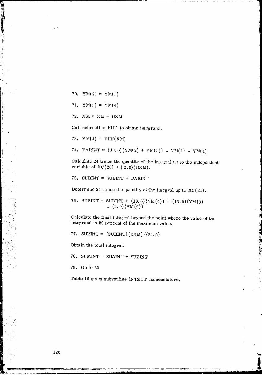
............... :: ...... :............. : ......................... =7..
iI ;
ti
:i 70. YM(2) = YM(:_)
' 71. YM(3)= YM(4)
{72. XM =: XM + I)XM
C'lll subroutine Flip to obL:tin integrand.i:
7:3. YM(O)_ I_m,_(XM)
7,t. I'AmNT-- (la.0)(YM(2) + YM(:_))- YM(1) - YM(4)
Calculate 24 times the qual_tity of the integral up to the independent
variable of XC(20) + (2.0)(DXM).
75. SUBINT = SUBINT + I)ARINT
: Determine 24 times the quantity of 'the integral up to XC(21).
".." 76. SUBINT = SUBINT + (10. 0) (YM (4) ) + (16.0)(YM(3)::: - (2.0) (YM(2))
•.:.. .:
•.,. - Calculate the final integral beyond the point where the value of the
.... intcgrand is 20 percent of the maximum value, i• ...'_. i
.... 77. SUBINT = (SUBINT)(DXM)/(24.0) iI
(..
: ,......... Obtain the total integral, t• , 1
: -, ....:, 78. SUMINT = SUAINT + SUBINT
.'...
79. Go to 22
Table 10 gives subroutine INTZET nomenclature.
120 k
t
00000003-TSA13
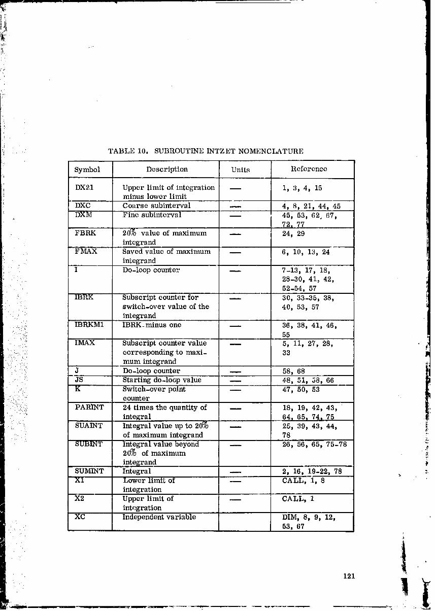
L
. TABLE 10. SUBROUTINE INTZET NOMENCLATURE
Symbol Description Units Reference
DX21 Upper limit of integration -- 1, 3, 4, 151 minus lower limit
DXC Coarse subinterval m 4, 8, 21, 44, 45
DXM Fine subinterval -- 45, 53, 62, 67,
72, 77FBRK 20% value of maximum _ 24, 29
integrand
:, . FMAX Saved value of maximum -- 6, 10, 13, 24!' . integrand
.... I Do-loop counter -- 7-13, 17, 18,.. 28-30, 41_ 42,
52-54, 57
_ IBRK Subscript counter for -- 30, 33-35, 38,
" " switch-over value of the 40, 53, 57• integrand
:i_,2:: IBRKM1 IBRK_minus one -- 36, 38, 41, 46,.... :_:; 55
;-:': IMAX Subscript counter value 5, 11, 27, 28,
•__"_:.!: corresponding to maxi- 33:ii:!:.:•:::.::*:.i: mum integrand
i
• :..": :. J Do-loop counter -- 58, 68..-. _: JS Starting do-loop value -- 48, 5i, 58, 66
•,, K Switch-over point -- 47, 50, 53: .:_: counter
_::::i:!!:..._:i PARI'NT 24 times the quantity of -- 18, 19, 42, 43, "• ."::i:_.' .. integral 64_ 65, 74, 75
i. _:i, '"'SUAINT Ir_tegral value up to 20_ -- 25, 39, 43, 44, _:
- of maximum integrand 78SUBINT Integral value beyond -- 26, 56, 65, 75-78 :_
20% of maximum_7
integrand
SUMINT Integral -- 2, 16, 19-22j 78 _ :-Xl Lower limit of CALL, 1, 8
integration
X2 Upper limit of --- I CALL, 1integration
XC Independent variable DIM_ 8, 9, 12,.... 53, 67
. 121
00000003-TSC01

i
,!
; i TABLE 10. SUBROUTINE INTZET NOMENCLATURE (Concluded):j Symbol Description Units Referencei
t XM Independent variable -- 53, 54, 62, 63,corresponding to fine 67, 72, 73
I: subintercalsi, XMAX Saved value of the m 12
independent variabl.e
corresponding 'to maxi-
mum value of integrandYC Integrand -- DIM, 9, 10, 13,
16, 18, 20, 29,39, 42
YM Integrand corresponding -- DIM, 54, 56, 59-: to fine subintervals 61, 63, 64, 69-
74, 76
ZINT Saved value of integral CALL, 22
00000003-TSG02
,'._,
SUBROUTINE MAINTB
Subroutine MAINTB provides the maiu control for the i:urbulent
boundary layer program.
COMMON BLOCKS
,_ COMMON block INPUT is used.
TBL SUBROUTINES
MAINTB calls subroutine DIRECT.
FORTRAN SYSTEM ROUTINES
No FORTRAN library routines or built-in FORTRAN functionsare used.
SOLUTION METHOD
• Initialize step-size indicator.
:.: ....
....•!:} i. IDXMAX = 0 II
:" '" 'i
Call the overall flow control program.
2. CALL DIRECT
• :_ Table 11 gives the nomenclature for subroutine MAINTB,
_' TABLE 11. SUBROUTINE MAINTB NOMENCLATURE _'
Symbol Description Units Reference ._T
IDXMAX Indicator for previous value -- /INPUT/, 1
of step size or to compute the " ':-step size
= 0, compute step size;= 1, use previous step size
s
123
00000003-TSC03
!
SUBROUTINE QUITS
Subroutine QUITS is entered when an error has been detected in the
input or if an unreasonable number has been calculated during execution. Itprints out appropriate error statements and the contents of the COMMON
blocks. If consecutive cases are considered, the next case is c_lled for.
, COMMON BLOCKS
COMMON blocks COFIIF, CSEVAL, INPUT, INTER, LOOKUP,OUTPUT, SAVED, and TABLES are used.
TBL SUBROUTINES
Subroutines BARCON, BARPRO, BARSET, CFEVAL, READIN,SEVAL, STARTS, and XNTERP call QUITS.
QUITS calls subroutine DIRECT.
" FORTRAN SYSTEM ROUTINES ---"
No FORTRAN library routines or built-in FORTRAN functions are ._•:. :::
:(ii::;. used.
.... CALLING SEQUENCE• ."'
..... The subroutine calling sequence is:
• CA LL QUITS
- _,
_ SOLUTION METHOD _ : _
Print out error statement.
v&
1. WRITE error message
Print out COMMON block/COFIIF/°
2. WRITE IFINT, AFINT, BFINT, CFINT, MMINT, TFINT
Print out COMMON block/INPUT/.
].24
00000003-TSC04
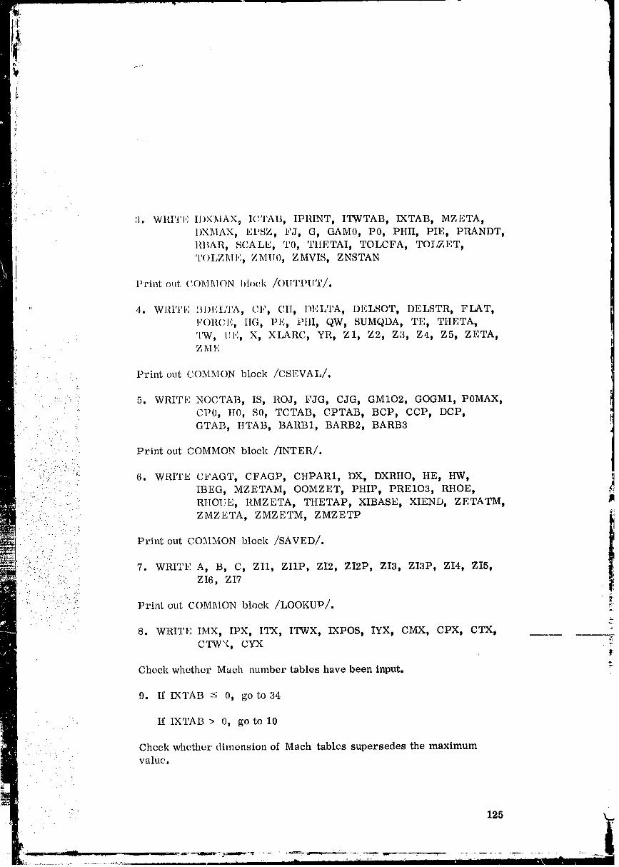
3. WRITE IIIXMAX_ ICTAB, IPRINT, ITWTAB, IXTAB t MZETA tIIXMAX, EPSZ, FJ, G, GAM0, P0, PHIl, PIE, PRANDT,
I llBAR, SCALE, I0, _ItlLTAI, TOLCFA, TOLZET,I
TOI_ZME, ZMIIO, ZMVIS, ZNSTAN
Print out COMI_ION 1)loc'l_ /OUTPUT/.
" '"'A " S '4. WI{I'I'I'; BI)I.,LI , ('.F, C,II, DI',LTA, DELOF, DELSTR, FLAT tl,'(_]_('I,'........ , IIG, PI':, PtlI, QW, SUMQDA, TE, THETA,
'l_vV, HI':, X, XLARC t YRt Z1, Z2, Z3, Z4, Z5, ZETA,ZM 1,:
.... Print out C.OIVIMON block /CSEVAL/,
' -; . *,i 5. WRITI" NOCTAB, IS9 ROJ, FJG, CJG, GM102, GOGMID POMAXt: " CP0, It0, S0, TCTAB, CPTAB, BCP, CCP, DCP,
.... -.... GTAB, ItTABt BARB1, BARB2, BARB3
Print out COMMON block /INTER/.
/.:'" '_: 6. WRITE CFAGT, CFAGP, CHPARI, DX, DXRHO, HE, HW,............... IBEG, MZETAM, OOMZET, PHIP, PREIO3, RHOE, _-.-.. ' ..: ...-'. RIIOUE, RMZETA, THETAP, XIBASE, XIEND, ZETATM, ]m
• . ..
": '? ......: .. ZMZETA, ZMZETM, ZMZETP _:_• 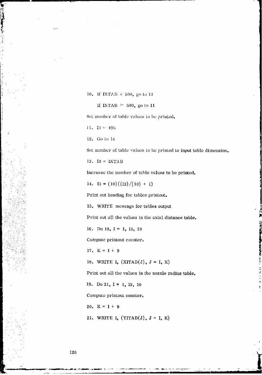
11. I3 = 495J_
12. Go to 14
Set mlmbcr of table -alucs to be printed to input 'table dimension.
.... 13. I3 = IXTAB
: . '-.- Inere_ se the number of table values to be prir_ted.
14. I8 = (lo1((I8)/(lo) + l)_. " "." .- 2":"_
'j•
'' " "-,,i Print out heading for tables printout.....;. ". :.
" );i_:::i?"i:_:_ 15. WRITE message for •tables output:.. ]:..:., ..-.'.
..../_:. : .: Print out all the values in the axial distance table.:,2.:. ../.-. • . .
16. Do 18, I = 1_ 13_ 10• ..- .....
• , . ._.,.....} . ....
': :: :. Compute printout eov.nter.i'. c .:
I.'" . . . ;: . "'.. ",
:i:: :¢i:iii_:i_,:il 17. K = I+ 9._, .., . .
£ ":_:.:..:i:_:': 18. WRITE I, (XITAB(J), J = I, K) i:
Pri_t out all the values in the nozzle radius table.
19. Do21_ I = 1, I3, 10
Compute printout counter.
20. K= I+ 9
21. WRITE I, (YITAB(J), J = I, K)
126
00000003-TSC06
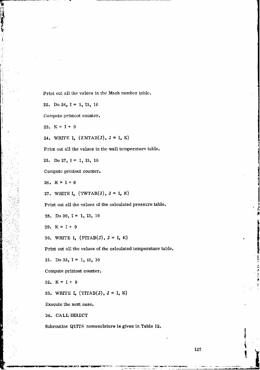
Print out all the values in the Mach number table.
22. Do24p I _ 1, I3, 10
Compute printout counter.
23. K= I+ 9i:
24. WRITE I, (ZMTAB(J), J = I, K)
Print out all the values in 'the wall temperature table.
25. Do27, I = 1, I3, 10
Compute printout counter.
..... 26, N = I + 9
-..
27. WRITE I,. (TWTAB(J), J = I, K)
--. : ...- :..,
. _'::" Print out all the values of the calculated pressure table. _!
:::=? .' :_ 28. Do 30, I = 1, I3, 10
"i::i 29. K= I + 9
. .. ,.
'_::: 30. WRITE I, (PITAB(J), J-- I, K)• ...::.: : " - .
;:; Print out all the values of the calculated temperature table..-...
!' 31. Do33t I = I, I3, 10 ii
Compute printout counter. ._
32. K= I+ 9r_
33. WRITE I, (TITAB(J), J = I, K)
Execute the next case.
34. CALL DIRECT
Subroutine QUITS nomenclature is given in Table 12.
!.. _
127
00000003-TSC07
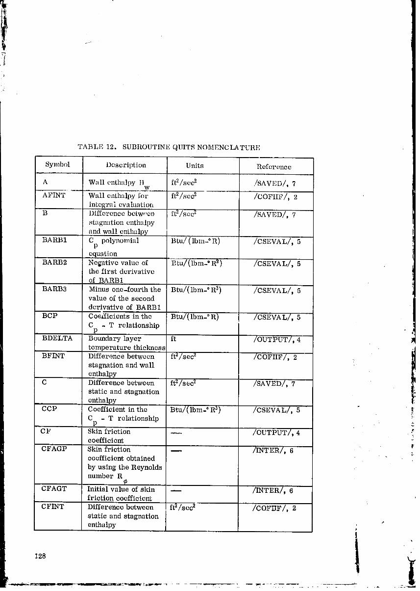
,i
TABLE 12. SUBROUTINE QUITS NOMENCLATURE
Symbol Description Units Reference
A Wall enthalpy II ft2/scc 2 ./SAVED/, 7W
AFINT Wall enthalpy for ft2/scc 2 /COFIIF/, 2integral eva luatiol_
B Difference betwoen ft2/sec 2 /SAVLD/, 7stagnation enthalpy
•rod wall e_thalpy
BARB1 C polynomial Btu/(Ibm- ° R) /CSEVAL/, 5p
equation
BARB2 Negative value of Btu/(lbm- ° R2) ' /CSEVAL/, 5•the first derivative
of BARB1
BARB3 Minus one-fourth the Btu/(Ibm- ° R3) /CSEVAL/, 5value of the secondderivative of BARB1
BCP Coeificients in the Btu/(lbm- °R) /CSEVA L/, 5C - T relationship
P
BDELTA Boundary layer ft /OUTPUT/, 4
temperature thiclmess l
BFINT Difference between ft2/sec 2 /COFIIF/, 2stagnation and wall
enthalpy
C Difference between ft2/sec 2 /SAVED/, 7static and stagnationenthalpy
CCP Coefficient in the Btu/(lbm- ° R3) /CSEVAL/, 5 " !C - T relationship .
p
C F Skin frietion -- /OUTPUT/_ 4 . :_coefficient _:
CFAGP Skin friction /INTER/, 6 :coefficient obtained
by using the Reynoldsnumber R
CFAGT Initial value of skin _ /INTER/, 6friction coefficient .'
CFINT Difference between ft2/sec 2 /COFIIF/, 2static and stagnationenthalpy , "
128 !
00000003-TSC08
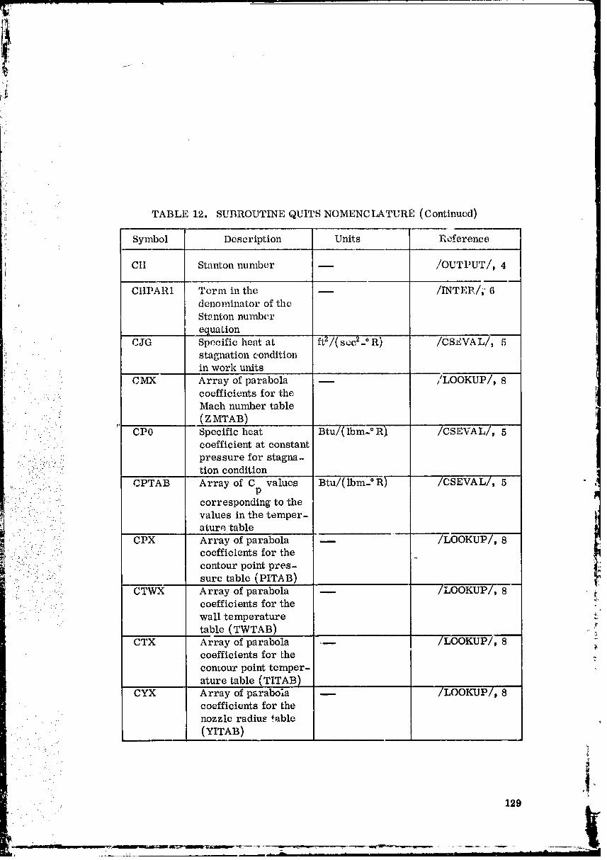
TABLE 12. SUBROUTINE QUITS NOMENCLATUR_ (Continued)
Symbol Description Units l=_cference
CII Stanton number -- ,/OUTPUT/, 4
CHPAR1 Term in the -- /INTLP./, 6.: denominator of the
S'tanton number
equation_JG Specific heat at ft2/(scc2- ° R) /CSEVAL/, 5
stagnation conditionin work units
• . !,
CMX Array of parabola -- /LOOKUP/, 8. :..., coefficients for the
. . . .
• Mach number •table• .. _'
• . v (Z MTAB)
... : CP0 Specific heat Btu/(Ibm'- ° R_ /CSEVAL/, 5: :., coefficient at constant
.... ':.. :. _: pressure for stagna-:" ::?::" /:: tion condition
" CPTAB Array of C values Btu/(lbm-°l_) /CSEVAL/, 5
::: .... . corresponding to the:";: ::"" ' values in the temper-
. :.. " _. aturetable
" :-: CPX Array of parabola -- /LOOKUP/, 8....... " coefficients for the
i/: !:!!!I..... :"i.,! contour point pres-
: :-':.-:::..... }:i-.. sure table (PITAB)
•_. ....... . CTWX Array of parabola /LOOKUP/, 8.... . .:- coefficients for'the _'
" ..... wall temperature
•table (TWTAB)
CTX Array of parabola --- /LOOKUP/, 8coefficients for thecontour point temper-
ature table (TITAB)CYX Array of parabola -- /LOOKUP/, 8
coefficients for thenozzle radius table
(YITAB)• .. . .*.
"•. ,!
• 129
00000003-TSC09

, t
_: TABLE 12. SUBROUTINE QUITS NOMI,NCLA_URI, Continued)'.ii
i
Symbol Description Units Reference
I)CI _ Cocificient in the BLu/(lbm-°R) /CSEVAL/, 5C - " relationship
P
I)I':LSOT Boundary layer -- _/, 4' shape factor
DI,LS2 l., Boundary layer ftdisplacementthickness
_ " DELTA Boundary layer ft
veloci'ty thicknessDX Weighted difference ft /INTER/_ 6 [
: of 'table values of the _axial distance
DXMAX Maximum length of f't. _, 3 l-. step size
' DXRHO One-tenth the ft _, 6: ....... difference between
• ....: .. axial distance points.....if" EPSZ Flow geometry _ _, 3 J
. . . ...
:_- • • : indicator
:: .. i".:.: . FJ Conversion factor _ IN_7, 3..... between 'thermal
• and work umts: .: y.
• -...:. : FJG FJ multiplied by G (ft2-1bm)/(Btu-sec 2) /CSEVAL/,I
_?:::i_... : 5:_.. :!:..,, FLAT Force normal to x- lbf" direction for two-
.... dimensional planar...... flow
FORCE Drag force in axial lbf /OUTPUT/, 4or x-direction
G Acceleration of __ _, 3
gravity used as aproportionali'tyconstant
GAM0 Specific heat ratio at _ _, 3
stagnation condition
G M102 One-half the specific _ _"
heat ratio at stag-nation conditionminus one
. .-_.---.,P-=].=-
O0000003-TSC10
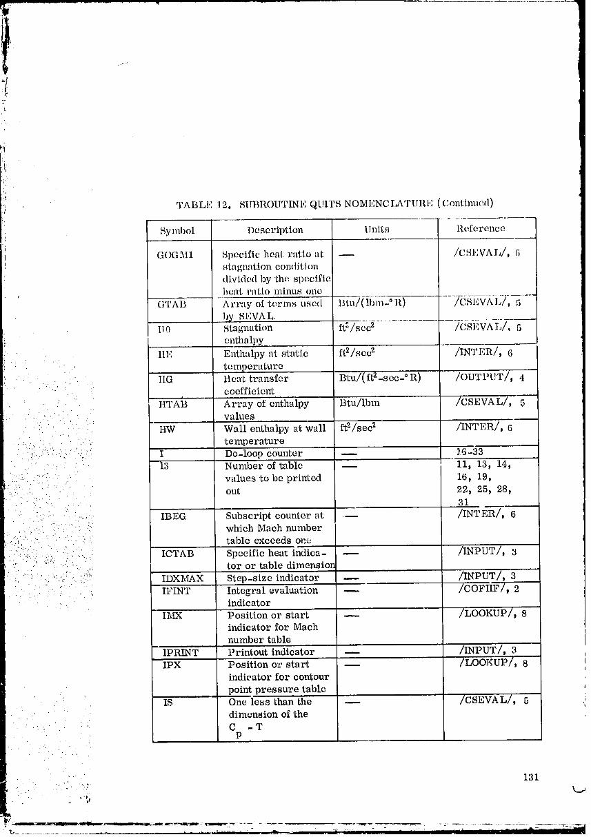
l'i
.'!
!:
',i TABLE 12, SUBROUTINE QUII_S NOMENCIATURE (Continued)
Symbol Description Units Reference
1 GOGM1 Specific heal: ratio at -- /CSI,VAL/, 5stagnation conditiondivided by the speed.fiehcat r:rtio minus one
' GTAB Al'ray of terms used I_tn/(lbm- °1l) -_ /CSEVAL/, 5
by SFVAL-I1.0 Stagnation ft:/sec 2 /CSI,VAL/, 5
enthalpy
• lie Enthalpy at static ft2/scc 2 /INTER/, 6temperature
ItG ttcat transfer Btu/(ft 2-see- ° R) /OUTPUT/, 4' ' : : coefficient
tITAi3 Array of enthalpy Btu/lbm /CSEVAL/, 5....... values
• . ". :
• ': .... : • HW Wall enthalpy at wall ft2/see 2 /INTER/: 6
....... temperature
./..._ ... I Do-loop counter -- 16-33" " " I3 Number of table -- 11, 13, 14,:, . . ..
::: "":* " " values to be printed 16, 19," • • out 22, 25, 28,
31
• - :-: : : ...:, IBEG Subscript counter at .-- /INTER]_ 6. " -: • .: which Mach number
:" )i i ICTAB Specific heat indica- -- /INPUT/, 3:, " '_. .i_). * ............ tot or table dimension
:*"_ IDXMAX Step-size indicator -- /INPUT/, 3_. " :_ ..:.._'"..".i.' . ..., ...-.
" . ' .:. ....... .. -. IFINT Integral evaluation _ /COFiiF/, 2..... . .. . .
indicator
Ih_ Position or start -- /LOOKUP/, 8indicator for Mach
number table
IPRINT Printout indicator -- /INPUT/, 3
IPX Position or start -- /LOOKUP/, 8indicator for contour
point pressure table• IS One less than the -- /CSEVAL/, 5
dimension of the
C -TP
.... 131
" _.2--
00000003-TSC 11
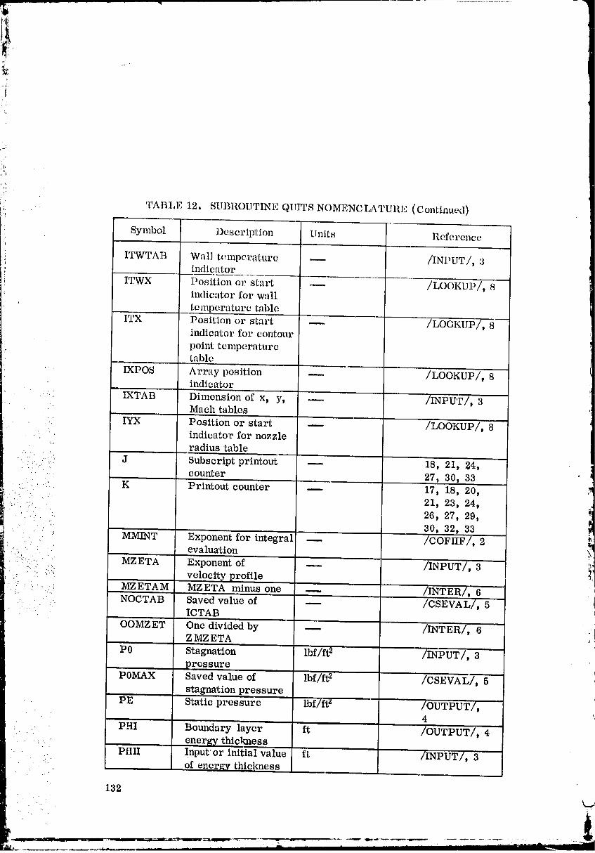
t.=
TABLE 12 SUBROUTINE QUIP,. NOMENCLATURE (Continued)
. Symbol Description Units Reference
ITWTAB Wall temperature m /INPUT/, 3indicator
ITWX Position or start _ /LOOKUP/,indicator for wall
' temperature table
ITX Position or stal:t _ ' /LOGKUP/, 8imlicator for cm_our
point temperaturetable
" IXPOS Array position _ /LOOKUP/, 8
L indicatorVATAB Dimension of x, y, _ /INPUT/, 3
Mach tables
. IYX Position or start -- /LOOKUP/, 8indicator for nozzle
radius table
..: .:_..... J Subscript printout m 18, 21, 24,: .... cour_ter 27, 30, 33
:.:.. .•..'. K Printout counter _ 17, 18, 20,..... •. 21, 23, 24,
::". ': 26, 27, 29,• 30, 32, 33
•_ MMINT Exponent for integral _ /COFIIF/, 2.:.... : evaluation
:/ .. . MZETA Exponent of _ /INPUT/ 3
.=- :! i_ :':;': velocity profile: MZETAM MZETA minus one _ /INTER/ 6
_. " .... :"i NOCTAB Saved value of /csEVAL/, 5• " ..... ICTAB
OOMZET One divided by --- /INTER/, 6Z MZ ETA
P0 Stagnation lbf/ft 2 /INPUT/, 3
pressurePOMAX Saved value of lbf/ft 2 /CSEVAL/ 5
• ,, stagnation pressurePE Static pressure lbf/ft z /OUTPUT/,
4
PHI Boundary layer ft /ouTPUT/, 4
energy thickness" PHIi' Inputor initial value" ft '/INPUT/,' 3
•"- of energy thickness
132
00000003-TSC13

,l!
¢ ',
!(.
'i;: . TABLE 12. SUBROUTINE QUITS NOMENCLATURE (Continued)
. Symbol Description Units Reference
PHIP Slope of energy -- /INTER/, 6thickness
PIE Circular construct lr m .. /INPUT/t 3PITAB Array of pressurc,_ lbf/ft 2 /TABLES/, 30
at cm_tour points
x, yPRANDT Prandtl number -- /INPUT/, 3
.. PRE103 Recovery factor -- ".... /INTER/_ 6QW Local heat transfer Btu/(ft 2..see) /OUTPUT/, 4
.... :- rate to the wall
• : • ::-_ ..... RBAR Specific gas (ft-lbf)/(lbm-°R) /INPUT/, 3" :" : constant
• " .. " RHOE Density at Boundary lbm/ft s ,)INTER/, "6
-.' :': ) :":' " lay,er edge:;: " :"_ RHOUE Flow density (p • v) lbm/(fti-sce) /INTER/, 6
._,.::-...= : at boundary layer•:..: :..:;:; .. e_l_e
• ... ;_.".;:;_.-" ,.;.
: ,..::.. .... :: RMZETA One divided by _ /INTER/, 6 _1'-:..:: :... ;v. ..... Z MZETP
! ):::?:::::(:::: ::'::(...: ROJ Specific gas Btu/( Ibm- ° R) /CSEVA L/ 5 llq_::.:;..:!(:..-: constant
" S0 Stagnation entropy Btu/(Ibm- ° R) /CSEVAL/, 5....=
_............. SCALE Contour scale factor or ft /INPUT/, 3..,..
' ": " SUMQDA Integrated heat Btu/sec /OUTPUT/, 4.:._.;.:._-........• • transfer rate
! .'::, • •;:: 2 TO Stagnation -" ° R /_u_//"'"""_ 3.. :.. ,.. _
•.. temperature :,'
!- TCTAB Temperature table °R /CSEVAL/, 5 _.for C values
p -_T
TE Static temperature ° R /ouTPuT/, 4 .¢TFINT Static temperature °R /COFIIF/, 2 "-
for integral evaluationTHETA Boundary layer ft /OUTPi.IT/_ 4
momentum thickness
TttETA Boundary layer ft /OUTPUT/, 4momentum thickness
.. .:, 133
00000003-TSD01

[i'
TABLE 12. SUBROUTINE QUITS NOMENCLATURE (Continued)
Symbol Description Units Reference
TttllIAI Input or initial ft /INPUT/, 3value of momentumthickness
TtlE'rAP Slope of momentum --- /INTER/, 6., thickness
-'I_ITAB Array of tempera'- ° R u. /TABLES/,tures at contour 33
points, x, y
TOLCFA Tolerance in --.. /INPUT/, 3
Cf - Cf R 0ite_-a'tion
-" TOLZET Tolerance in the -- /INPUT/, 3zeta interation
_:. : TOLZME Tolerance in:the gas /INPUT/, 3' property evaluation
...._,. !°°P
."- TW Wall temperature ° B. /OUTPUT/_ 4 .... _ TWTAB Array of wall tern- °R /TABLES/,
:.:.....
....: peratures at contour 27
:"_:":: points x, y _.l_:':.. I.• ' ":" UE Velocity of fluid ft/see /OUTPUT/, 4
1
...: X Axial distance ft /OUTPUT/, 4
. ii. XIBASE First value of ft " /INTER/, 6:.f: :_ axial distance..."._". table
I.. '._ XIEND Last value of axial ft /INTER/, 6 _.".: :: &
_. distance table _'
XITAB Array of axial ft /TABLES/,. 18 " -. i
distancevalues ,XLARC Arc lengthofthe ft /OUTPUT/, 4
contour,, ,m "
YITAB Array of nozzle ft /TABLES/, 21radius or contour
height
YITAB Array of nozzle ft /TABLES/,radiusor contour 21
height'j
i:.'
00000003-TSD02

ZI4 14 -- _ -p Sn (1 -S)dS _ /SAVED/, 7• ' • o Pe
• , , . •
. ...:.,.' i r
i : ZI5 15 = f -p Sn (1- 8)dS /SAVED/, 7
' , ". _ Pe
135" . /_
".. ""
!k
=_-=. _ .-- ...... _. , . . __.,_-_--- ....... _ ..... _.....................
00000003-TSD03
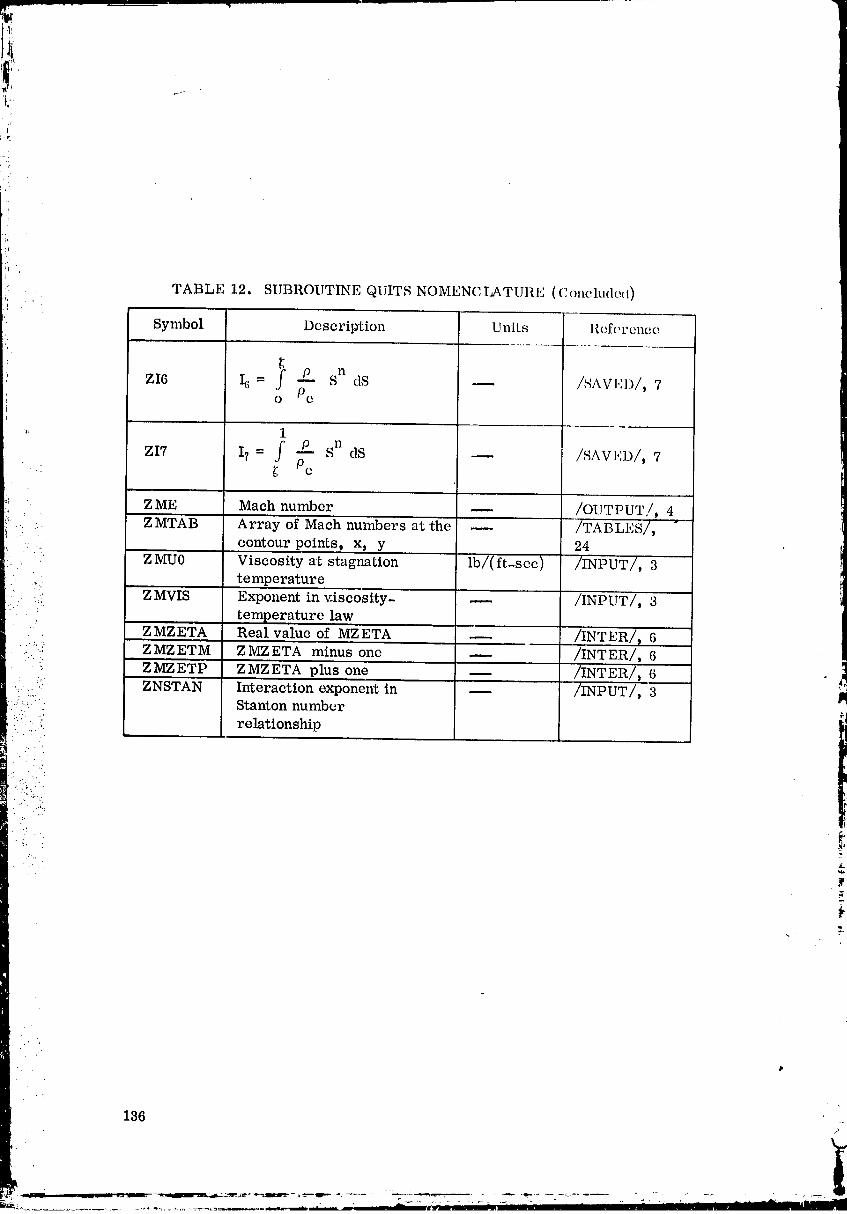
Ve*
,i
i'i
TABLE 12. SUBROUTINE QUITS NOMENCLATURI_ (C(mcludec 0i,'
)• Symbol Description Units llcfcrencc
ZI6 Ic, = I _ Sn dS -- /SAVI,;])/, 7o Pc
Sn dS -- /SAVI,ID/, 7ZI7 I? = f Pc ;
ZME Maeh number -- /OUTPUT/, 4
.. ZI_ITAB Array of Maeh numbers at 'the -- /'I'ABLFS/,
• contour points, x, y 24
. ;. - ZMU0 Viscosity at stagnation lb/(ft-scc) /INPUT/, 3'temperature
_°.,
( :.:i ZMVIS Exponent in v.iseosity- -- /INPUT/, 3•temperature law
ZMZETA Real value of MZETA -- .. /II_TER/_ 6"" ZMZETM ZMZETA minus one --- /INTER/, 6
" ; _" ZMZETP ZMZ'ETA plus one -- /INTER/, 6
i' ZNSTAN Interaction exponent in -- /INPUT/, 3 i:,. Stanton number
. ,. relationshipB
• "'...- .
136
I
00000003-TSD04
,4L
.' SUBROUTINE READIN
Subroutine READIN first calls for single item variables such asintegers, constants, and gas constants. It then reads in tabular values such
as contour points, Mach number, and wall temperature. It prints out the
input and performs diagnostics to detect obvious inconsistencies in inputt quantities.
J
Before any input is read in, the following constants are set to their• nominal values and need be input only if different values are desired.
1. Contour scale factor SCALE = 1.0
2. Velocity power law MZETA "_ 7
...:.: : :_ exponent
" .: _ 3. Interaction exponent in ZNSTAN = 0.10_ ::. :*:_::' Stanton number relation
• :'. . ... . ... •
• . ..-..
.:-.i:-...::i_::!._:" :::_:- 4. Conversion factor between FJ = 778.20 (ft-lb)/Btu• ::.:i.. thermal and work units
:i:!:.::..:":}-;: 5. Sea level acceleration of G = 32.1740 (ft-lbm)/(lbf-see _) _*'_
i::: .i i_: :i i gravity:':::': . -:
• ::" 6. Tolerance in skin friction TOLCFA -- 1.0 × 10 "4
,..':. coefficient iteration loop
:" :i:_*. " -.... . • : 7. Tolerance in gas property TOLZME = 1.0 x 10 -_..... _.._. ..-:..:
:_: :!:' evaluation loops
•i: .. : 8. Tolerance in zeta iteration TOLZET = 0.00030loop _"
The first input card for each case is a title card containing Hollerith
information in columns 1 through 78. Input data are read in by the NAMELISTname NAM1. The variables that are included in the NAMI NAMELIST are
as follows: CPTAB, DXMAX t EPSZt FJ, G, GAM0, ICTAB, IPRINT_
ITWTAB, IXTAB, MZETA, P0_ PHIl, PRANDTt RBAR, SCALE_ T0_TCTAB, THETAIt TOLCFA, TOLZET t TOLZME, TWTABt XITAB,
ZMTAB, ZMU0, ZMVIS, ZNSTAN
.' . ,.. •
• 137
:,i (2OM MON B LOC KS
COMMON blocks CSLVAL, INPUT_ and TABLES are used,
1 I t'TBL SI_BROUTINLS
Subroutine DIRECT calls READIN.
': IU':ADIN c_llls subroutine QUITS.
• FORTRAN 5YSTEM ROUTINES
7. TOLZME = 1.0 x 10 -?
8. TOLZET = 0.00030
Save value of maximum step size from previous case.
• '..•
00000003-TSD06

' 9. DXMAXO = DXMAX
i Set maximum step size to check whether saved value from
previous case is t.o be used.
10. DXMAX -- -28982.0
'_ Read in title for this case.
•. . 11. READTITLE
" Read in name list data for this case.
..... " " 12. READ ($NAM1)!:... " i:..'. : _:.
. ,. i.":.i!-- Cheek whether a new value for the maximum step size has been Input.
-.':. : • ..
. '.. • :(:" -.:'.fi::" : '- ., .-.
•-.:. 13. If DZMAX ¢ -28982.0, go to 17
i/:'/!::-::-i::::.::::,_.., - If DXMAX - -28982.0, go to 14,. =.,'..::: . !
: " ::':i ..:.i ":"i:_..-., .......... Check whether step size from previous case or computed value must be
il:-::i-:(:!"::'::: i. :ii:: us ed,
L 2
?:_ 14_ If IDXMAX = 0, go to 21
: . ::::i_:i:. ::i" If IDXMAX ¢ 0, go to 15.... : .......
•:. ':'::i'i:_':;:: Set maximum step size to saved value from previous case.
i:: '::ii?:.:.. :. 15. DXMAX = DXMAXO
16. Go to 22
Step size has been input; check whether actual step size must be _
computed.
17. If DXMAX <- 0.0, go to 20
... If DXMAX > 0.0, go to 18
' " ..- Sct step size indicator to use the same step size.
. ,,:. "
19. Go to 22
Set step size indicator to use a new step size.
20. IDXMAX = 0
" Compute value of maximum s_ep size to be used.
21. DXMAX = ((XITAB(IXTAB) - XITAB(1))/(100.))(SCALE)
Write out the title heading for this case,
22. WRITE TITLE
Initialize error indicator to zero.• . .." .
-" 23. IERROR = 0
::. :.::. Print out the velocity profile exponent.
,.:: i:..: 24. WRITE MZETAL.,:.._'" ,:' -:'
::::_.::" Check value of velocity profile exponent.• . . . .
mm_m• . .
._ • 25. If MZETA -_ 0, gore28: .. :....:. :- :..
• :":(!':::_ If MZETA < 0, goto 26. .-..
:" "_' . If the velocity profile exponent is in error, print out message.'2
• i
" 26. WRITE error message about input value.¢
Set input error indicator to one, _
27. IERROR-- 1
Write out printout indicator.
140
00000003-TSD08

,, Chock wllue of printout indica tot.,q
29. If IPRINT = I o1: IPRINT = 0, go to :]2i
,i! If IPI_IN'I' ¢ ] nnd IPRINT ¢- 0, go to 30
The printout indicator is in error; l)rint out message.
" 30. Wl_I'rE error message about input value
Set input error indicator to one.
31. II,:I{ROI{ = 1
Print out dimension of x, y, and M tables...... '- .
-" 32. WRITE .UKTAB
." .. . " • .
. Check whether value of dimension indicator is within limits.
•. (:::............_: 33, If IXTAB > 4 and IXTAB < 500, go to 36
• " .:- .. - If IXTAB < 4 or IXTAB > 500, go to 34... , ._
:::..... " " Dimension indicator is below minimum limit or above maximum limit,
...... 34. WRITE error message about input value.,...
:: : o rori a catotoo o.• [... .
... ...
....• . :: ..:_ 35. IERROR = 1:, ......,-
........ Print out specific heat indicator.
36. WRITE ICTAB
Check specific heat option to be used.
37. If ICTAB = 0, go to 41
If ICTAB ¢ 0, go to 38
• . . ".
141
. • .. . . .. ,
00000003-TSD09
!
Tabular specific heat option is called for, cheek whether dimension
_! is within limits.
i] 38. If ICTAB >-_ ,_"and IC1At" _ r= 20, go 1:o41
If ICTAB < 3 or I(,IAlt > 2(1, 14oI.o 49
Dimensi(m indicator is out of limits.c
39. WRITE error message about input wthle
Set input error indicator to one.
40. IERROR = ]
Write out wall temperature option indicator.
.::.., 41. WRITE ITWTAB
. Check on value of wall temperature option indicator.- "G. '.'....
42. If IITWTABI = 1 or ITWTAB = 0_ go to 45
:... " ...:5 ]_
.......... If IITWTABI ¢ 1 and ITWTAB ¢ 0, go to 43
:.. Wall temperature indicator is in error.
• ::' .: 43. WRITE error message about input value
": i Set input error indicator to one,
• " " 44 IERROtt = 1 ,
Print out the value of the stagnation temperature.
45. WRITE TO "-
Check value of stagnation temperature for error•
46. If TO > 0.0, go to 49
142k..,
i
00000003-TSD10

'1,• 1!:
_. Stagnation temperature value is in error•
47. WRITE error message about input value
Set input error indicator to one•
48. IEIII{OR = 1
i
Print out the v,qlue of the stagnation pressure•
49, WRITE P0
Check value of stagnation pressure for error•
50. If P0 > 0.0, go to 53:',.. , ..
If P0 - 0•0, go to 51
Stagnation pressure value is in error,
. .:. ;. . - ...., . . , .
.... 51 WRITE error message about input value..... •
_ ' :.... Set input error indicator to one.
• ' 52. IERROR = 1
:. ' Print out stagnation value of the specific heat ratio.
: ': ":" 53. WRITE GAM0• .:. " ':- i'.
.... ..
....' :.•..: Check on specific heat ratio option indicator.
54. If ICTAB ¢ 0, go to 58 _-.
If ICTAB = O, go to 55
Constant specific heat is to be usedt cheek value of stagnation specifichea t ra tio.
55. If GAM0 > 1.0, go to 58
If GAM0 - 1.0, go to 56
.': . . .
143• .. ,:
.' _,_
00000003-TSD11

Stagnation specific heat ratio is in error.
aft. WRITI_ error message about input valtte
Set input error indicator to one.
57. II,:RHOII = ]
Print out the value of the Prandtl number.
58. WRITE PRANI)T
_, Cheek on value of the Prandtl number.
59. If PRANDT > 0.0, go to 62
If PRANDT --< 0.0_ go to 60
The Prandtl number is in error.
60. WRITE error message about input value
' Set input error indicator to one.
51. IERI':tOR = 1
Print out the stagnation viscosity.
i.i=[• 62. WRITE Z_;(J0
_: Check on value of the stagnation viscosity. _i
63. If ZMU0 > 0.0, go to 66
If ZMU0 - 0.0, go to 64
The stagnation viscosity is in error.
64. WRITE error message about input value
Set, inpu_ error indicator _o one.
!,i,t'
"; • 65. IERROR = 1
_ Print out the temperature-viscosity relation exponent.I
'i 66. WRITE ZMVI8
Print out the Stanton number interaction exponent.
67. WRITE ZNSTAN
.' ..:.
• Print out the maximum length of the step size.
::_,.:: 'i 68. WRITE DXMAX
,,. Check whether the sonic point start procedure is to be used.
t( ::::'.... ... 69. If TttETAI < 0.0, go to 72.:,.:
.: If THETAI -> 0.0, goto 70
•" :_': Prir_t out the initial value of the momentum thickness. ,_
(_:i,i:_::.:, 70. WRITE THETAI P
" _ '_' Print outthe initial value of the energy thickness......
:"' Print out the flow geometry indicator.
:! " 72. WRITE EPSZ _,
Check value of the flow geometry indicator. ,
73. If EPSZ= 0.0or EPSZ -- 1.0, go to 76
If EPSZ ¢ 0.0 and EPZS ¢ 1.0, go to 74
The flow geometry indicator is in error.
74. WRITE error message about input value
O0000003-TSF01
Set input error indicator to one'.
75. IERROR -- 1
Print out the vahm of the specific gas constant.
76. WRITE IIBAR
Check value of specific gas constant.
77. If RBAR > 0.0, go toS0
i. If RBAR _ 0.0, go to 78
The specific gas constant is in error..:...
78. WRITE error message about input value
Set input error indicator 'to one.
79. IERROR = 1Print out the conversion factor between thermal and work units. P
80. WRITE FJ
' Check value of 'the conversion factor.
!..
81. If FJ > 0.0, go to 84
If FJ -< 0.0, go to 82
The conversion factor is in error. .
82. WRITE error message about input value
Set input error indicator to one.
83. IERROR - 1
Print out the value of the acceleration of gravity at sea level.
84. WRITE Gi "
146 i
._ :-. _ _ _ _ _ - -_mmm,_... r . z_.... ._wr_...._.-,,_ _ _-_-.-
00000003-TSF02
W:
r ,_
ill
Check value of 'the acceleration of gravity.
85. If G > 0.0, go to 88
If G _ 0.0, go to 86
The value of the acceleration of gravity is in error.
86. WRITE error message about input value
Set input error indicator to one.
87. IERROR = 1
. Print out thc nozzle contour scale factor,
': 88. WRITE SCALE
• , Check whether the skin friction coefficient tolerance has been input.
...:_:!"ii":--i=: 89. If TOLCFA = 1.0 x 10 -4, go to 91
...."......... If TOLCFA ¢ 1.0 x 10 -4, go to 90 lP:":: _.'i.'. ',: :"". ...
:- .-.:....::' Print out the input value of the skin fvlction coefficient tolerance.
.... , ...
::.:.:...,.:. ::: : _ 90. WRITE TOLCFA
: ::%._" ._::;:: Cheek whether the zeta iteration tolerance has been input."::. "".3
_i:. ':..i;. :- 91. If TOLZET = 0.00030, go 'to 93 _:_
If TOLZET ¢ 0.00030, go to 92 J¢
Print out the input value of the zeta iteration tolerance.
92° WRITE TOLZET
Check whether the gas property evaluation tolerance has been input.
-: 93. IF TOLZME = 1.0 × 10 -T, go to 95
IF TOLZME ¢ 1.0 × 10 -T, go to 94
• "-.
.. 147 t'
O0000003-TSF03

Print out the input value of the gas property evaluation •tolerance.
94. WRITE TOI,ZME
Check whether 'the specific heat •table has been input.
95. If ICTAB _ 0, go to 112t
If ICTAB > 0, goto_96
Print out a heading for the specific heat/temperature tables.
;i 96. WRITE heading for specific heat/temperature tables
_ Print out the specific heat/temperature tables.
" 97. WRITE (I, CPTAB(I), TCTAB(I), I--- 1,ICTAB)
........ Set limit for do-loop. 1'' 98. H-- ICTAB - 1
•.:::.!::; 99. Do 103, I = 1, II !_
Check whether •temperature table values are monatonically increasing.
100. If TCTAB (I + 1) > TCTAB (I), go to 103
• :"....
' If TCTAB (I + 1) -< TCTAB (I), go tol01
_. Temperature table values are not in the proper order. :
101. WRITE error message about temperature •table .,
Set input error indicator to one.
102. IERROR = 1
103. Continue
Check the first value in the temperature table.
148
1
00000003-TSF04

,_i_
l 104. If TCTAB (1) > 0.0, go to 107
If TCTAB (1) _ 0.0, go to 105
The first temper:rture table value is ill error.
105. WRITE error message about temperature tablema
Sct input error indic:trot to onc,
106. IERROR = 1
: 107. Do 111, I = It ICTAB
Check whether specific heat •table values are greater than zero.
:-i'..". 108. If CPTAB (1) > 0.0, go to 111
' If CPTAB (1) -< 0.0, go to 109: :,.;!_- ?_;:• -:. Specific heat table values are in error.
.. _ . (,.,
7":.i.:' p"/i':_."i_' 109. WRITE error message about specific heat tablei::_. :17::
Set input error indicator to one.....
: .. :':( 110. IERROR = 1
..... 111. Cor_tinue
:: : 112. Do 116, I = 1, IXTAB _'•
Check Mach number 'table values. • _
113. If ZMTAB (I) > 0.0, go to 116 ,
If ZMTAB (I) -< 0,0, got'J 114
The Mach number table is in error.
114. WRITE error message about Mach number table' ' i
. .7. i
149 !
O0000003-TSF05

Set input error indicator to one.
115. IERROR = 1
116. Continue
Set limit for do-loop.
117. II = IXTAB - 1
118. Do 122, I = 1, II
Check whether axial distance table values are monatonically increasing.
119. If XITAB (I + 1) - XITAB (I), go to 122
If XITAB (I + 1) < XITAB (I), go to 120
The axial distance table values are not in proper order.
120. WRITE error message _bout the axial distance table
Set input error indicator to one.
121. IERROR = 1 l
)122. Continue
Check wall temperature option indicator.
123. If ITWTAB < 0, go to 133
If ITWTAB -- 0, go to 130
If ITWTAB > 0, go to 124
Tabular wall temperatures are to be used.
124. Do 128, I -- 1, IXTAB
Check whether wall temperature values are greater than zero.
150 _. _- ._ _ I........ u______:.._.
O0000003-TSF06

,_ ...
:! 125. If TWTAB (I) > 0.0, go to 128
JIf TWTAB (I) _ 0.0, goto 126
The wall temperature table is in error.
126. WRITI,: error message about wall temperature table
Set input error indicator to one.
127. IERROR = 1
128. Continue
129. Go to 133
Constant wall temperature option is to be used; check for propervalues.
' ...... _ 130 IfTWTAtt(17 > 0.0, go to 133':,.
• If TWTAB(1) -< 0.0, go to 131
_.: Input value of constant wall temperature is in error.
131. WRITE error message about wall temperature
::_ Set input error indicator to one.
"" 132. IERROR = 1_. _,
Check whether contour scale factor has been input. _.-
133. If SCALE = 1.0, go 'to 137
If SCALE ¢ 1.0, go to 134 "-
Scale factor has been input_ calculate real values for x and y.
134. Do 136, I = 1, IXTAB
' 135. XITAB(17 = (XITAB(17) (SCALE)
!!
151 i
O0000003-TSF07
136. YITAB (I) = (YITAB(I))(SCALE)
Cheek wall temperature option indicator.
137. If ITWTAB < 0, go to 139
If ITWTAB = 0, go to 138
If !TWTAB > 0, go to 142
:: Print out value of consta_t wall temperature to be used.:)
'.. ': 138. WRITE TWTAB(I}
.:. Print out heading for x, y, and NI tables.
': ?i
:.: .:: 139. WRITE heading for x, Yt and M tables
Prir_t out input values of xt Yt and M tables,., .--.:, ,':
......,..! 140. WRITE (I t XITAB(I), YITAB(I), ZMTAB(I), I = 1, IXTAB)
i:"@;::_.!:. 141. Go to 144 II:':"i .;3-t '. _..0'
" '..-.". Prir_t out heading for x_ y, M, and T tables.• ", :' W
. . ::.
:!_:..i.-_ 142. WRITE heading for xt y, M_ and T tables:i:i.b.;i.:: w
•_:);_ Print out input value_, of xt Yt Mt and T tables.
_"..... 143. WRITE (I, XITAB(I) , YITAB(I) , ZMTAB(I) ,-" TWTAB(I}, I = 1, IXTAB)
Check dimension indicator for xt y, and M tables. •_
144. If IXTAB - it go to 150
If IXTAB > I t go to 145
Check whether axial distance values are in monatonically increasingorder.
145. Do 149_ I = 2t IXTAB
2
O0000003-TSF08
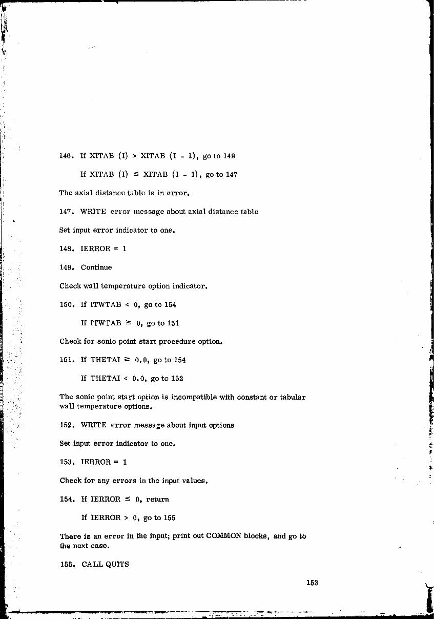
!.
.!
.,! 146. If XITAB (I) _ XITAB (I - 1), go 'to 149
If XITAB (I) -- XITAB (I - 1), go to 147i.
i The axial distance table is in error.
i 147. WRITE err'or message about axial distance table
Set input error indicator 'to one,
148. IERROR = 1
.. 149. Continue
• j
- Check wall temperature option indicator.
:;. 150. If ITWTAB < 0, go to 154
" ' If ITWTAB -> 0, go to 151
Check for sonic point start procedure option.. • • _,
i.::I:'_ 151. If THETAI -_ 0.0, go tO 154 lm
• . i'::: If THETAI < 0.0, go to 152
:: The sonic point start option is incompatible with constant or tabular....:::, wall temperature options.
•:..,. 152. WRITE error message about input options _:
Set input error indicator to one.
153. IERROR = 1
Check for any errors in the input values,
154, If IERROR < 0, return
If IERROR > 0, go to 155.q
There is an error in the input; print out COMMON blocks, and go tothe next case.
155. CALL QUITS
153
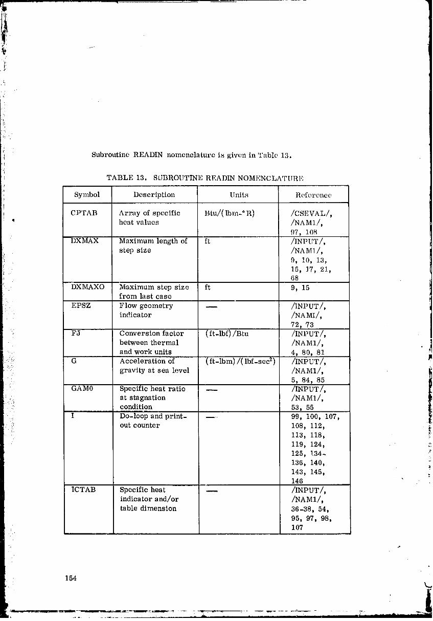
'_ Subrot_tine READIN nomenclature is given in Table 13.
'i
TABLE 13. SUBROUTINE READLN NOMENCLATURE
Symbol Description Units Reference
CPTAB Array of specific Btu/( Ibm- ° R) /CSEVAL/,' heatvalues /NAM1/,
97, 108DXMAX Maximum length of ft /INPUT/,
step size /NAM1/,
9, !0, 1.3_• 15, 17, 21,
68
DXMAXO Maximum step size ft 9, 15from last case
EPSZ Flow geometry -- /INPUT/,indicator /NAMI/,
72, 73
• FJ Conversion factor (ft-lbf)/Btu /INPUT/,between thermal /NAM1/, ]
,:ZI and work units 4, 80, 81
ii G Acceleration of (ft-lbm)/( lbf-sec 2) /INPUT/, ]M
gravity at sea level /NAM1/,5, 84, 85
I
" GAM0 Specific heat ratio m /INPUT/,:. at stagnation /NAM1/,
. .... condition 53, 55
I Do-loop and print .... 99, 100, 107,
:' out counter 108, 112, i:!' 113, 118, "'
119, 124,
125, 134- :_136, 140,
143, 145,146
ICTAB Specificheat -- /INPUT/,indicatorand/or /NAM1/,
tabledimension 36-38, 54,
95, 97, 98,107
O0000003-TSFIO
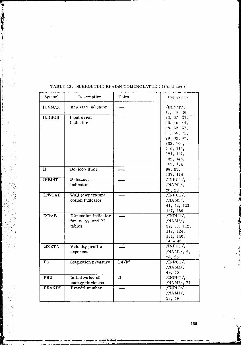
:il
! TABLE 13. SUBROUTINE READIN NOMENCLATTII{E ((:,)nHmu.,0
Symbol Description Units l_elY,'renee
I1)XMAX Step size indicator -- /INP[TJ'/,14, I_, 20'_' 3TERROR Input error _ _,_, 27, :1,
,: indicator ;I.5, ,lo, 114,d_, !_2, bT,
(i:l, (ili, 75,'79, 8;I, 87,102, 106,
.... I I O, 1] 5,121, 1.,7,
" i;12, 148,
:. 153, 154'.:. • II Do-loop limit _ 98, 99,
: .. 117, 118
" IPRINT Print-out -- /INPUT/,: " 2 : indicator /NA M1/,
• • '::.;: 28, 29
• ::={" ITWTAB Wall temperature _ /INPUT/,.. , : option indicator /NAM1/,
:"::.i" 41, 42, 123, ,_"' ":ii. 137, 150
:.. :i."]""= IXTAB Dimension indicator -- /INPUT/,;i for x, y, and M /NAM1/,
. :..!::..:.: tables 32, 33, 112,: '_:"* 117, 124,-::: ...?.
• • 134, 140, :: _'. 143-1.4.5 .
7 ". MZETA Velocity profile -- /INPUT/,exponent /NAM1/, 2,
24, 25 ::'
P0 Stagnation pressure lbf/ft _- /INPUT/, :/NAM1/,49, 50
PHII :nitial_va lue of ft /INPUT/,energy thickness /NAM1/, 71
PRANDT Prandtl number -- /INPUT/,
/NAM1/,.... 58, 59• .. ,.
i'
i
:!i " TABLE 13, SUBROUTINE READIN NOMENCLATURE (Continued)
.i Symbol Description Units Reference
i RBAR Specific gas (ft-lbf)/( Ibm- ° K) /INPUT/,
! constant /NA M1/,i
: 76 _ 77: SCALE Contour scale _ /INPUT/,
factor /NAM1/, 1,21, 88, 133,
135, 136
T0 Stagnation ° R /INPUT/,temperature /NA M1/,
45, 46TCTAB Array of tem- °R /CSEVAL/,
perature values /NAM1/,
corresponding to 97, 100, 104
•:• the specific heattable values
THETAI Initial value of ft /INPUT/,
:::...: momentum thickness /NAM1/,: : 69, 70, 151
• ":.:.-" .... TITLE Array of Hollerith DIM, 11, 22
:....... • characters input t• . ( -.
: i ]: as the title heading !_•. .:._ for the case being
• :: run
-:_ ::-'- TOLCFA Skin friction /INPUT/,
?-i.:::! iteration tolerance /NA M1/, _!h
6, 89, 90 "_
i:.": i_i' TOLZET Z eta iteration --. /INPUT/,' ": •tolerance /NAM1/, 8,_" : 91, 92
TOLZME Gas property __ /INPUT/,evaluation tolerance /NAM1/, 7,
93, 94
TWTAB Array of wall °R /TABLES/,•temperature values /NAM1/,
125, 130,138, 143
. 156
00000003-TSF13
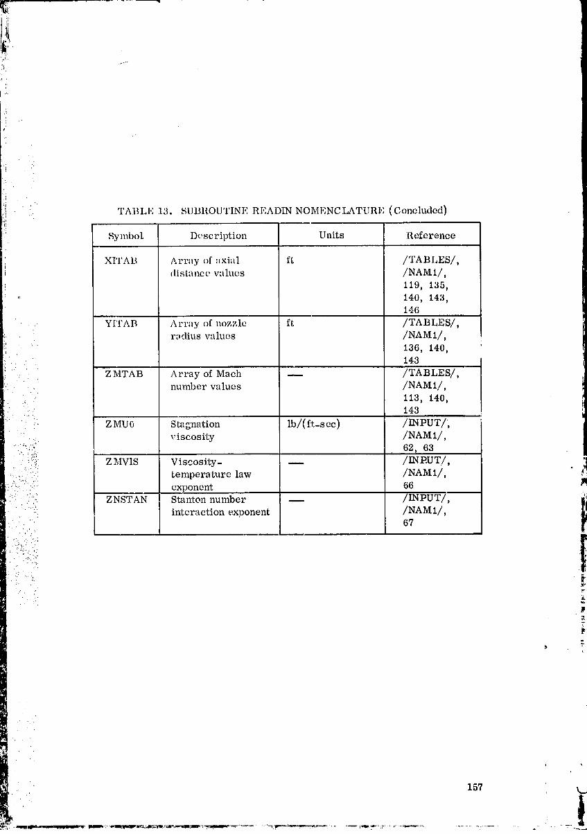
TABLI': 13. SUBROUTINE RI!:ADIN NOMI,,NCLATt RL (Concluded)
._ Symbo_ Dcscription Units Ref.erence
XITAB Array of :lxial ft /TABLES/,distance wllucs /NAM 1/,
119, 135,
': 140, 143,146
YITAB Array of nozzle ft /TABLES/,
r,_dius w_lucs /NAMI/,
136, 140,' 143
" ZMTAB Array of Mach -- /TABLES/,
:... • , number values /NAM1/,•" 113, 140,..
143
• " .. Z MU0 S tagnation lb/(ft-s ec) /INPUT/,
......_,_i viscosity /NAM1/,': :'ii_!: ' _ 62, 63
• .._..'): Z MVIS Viscosity- -- /INPUT./, ]:.. ::_"...i: temperature law /NAM 1/, _:_.
i::.!:f_::.• .,.:i:- exponent 66
:": ::":: ZNSTAN Star_ton number /INPUT/, ll
.... •"::: intera c tion exponent /NAM 1/,
• " " F
_.-"-':i!....._:
:, .._;-
" _.-. ,'
P
157 k.
1
O0000003--TSGO ]
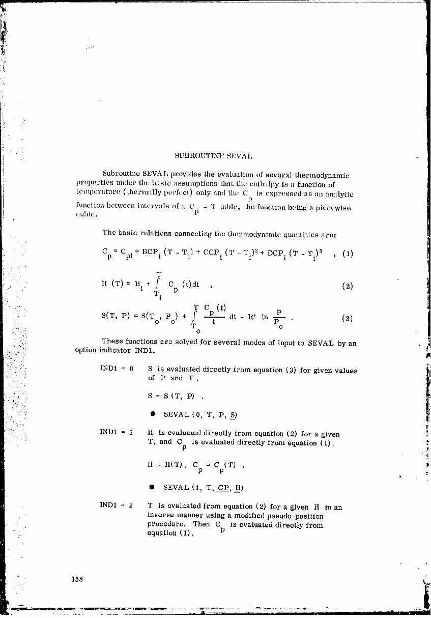
SUBROUTINE SEVA L
Subroutine SEVAL provides the evaluation of seve, ral thermodynamic
properties under the basic assumptions that the enthalpy is a function of
t(_mperature (thermally perfect) only and the C is expro.sscd as an analyticP
function botween inturvals of a C - T table, the function being a piecewisecubic. P
The basic relations connecting the thermodynamic quantities arc.
C = C + BCP. (T -T.) + CCP (2' -Ti)2+ DCP. (W -Wi)3 , (1)p pi 1 1 i 1
.: ' ' T
H (T) = H. + f c (t)dt , (2)T. P
1
T C (t)
• S(T, P)= S(T Po) + f P dt- R' in T . (3)o' tT o
:[L:':_ 0):_:,
.: These functions are solved for several modes of input to SEVAL by an
::-". option indicator IND1.
:.:i::_:.)-:.. JND1 = 0 S is evaluated directly from equation (3) for given values- .... of P and T
• "... ":
S= S(T, P) .:,.... ..
.'., .
•:!:-: • SEVAL (0, T, P, S)...-
_ IND1 = 1 H is evaluated directly from equation (2) for a given..... T, and C is evaluated directly from equation (1).
P
n = H(T), C = C ('r) .P P
• SEVAL (1, T, C___p_P,H)
IND1 = 2 T is evaluated from equation (2) for a given H in anin_,erse manner using a modifmd pseudo-position
procedure. Then C is evaluated directly from. equation (1), P
158
00000003-TSG02
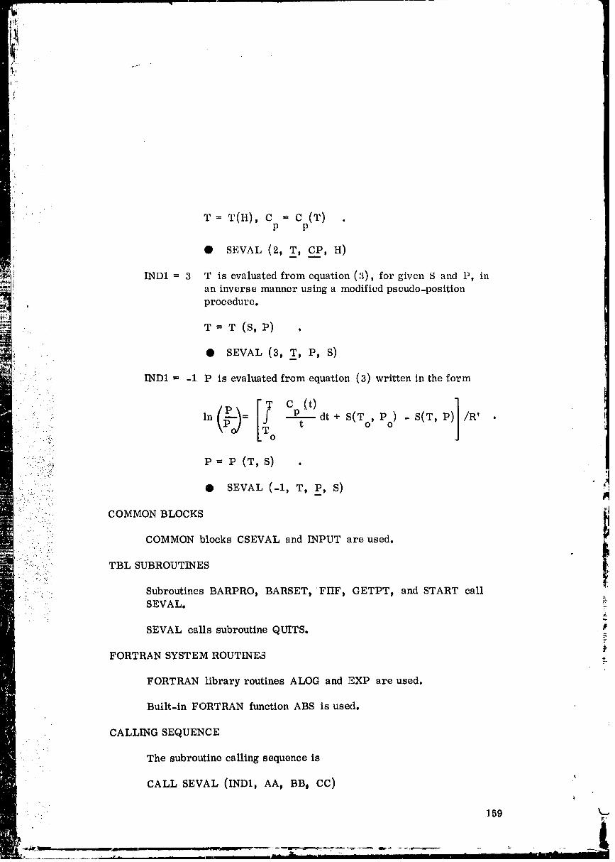
i
I
' T = T(H), C = C (T) .P P
• SEVAL (2, T, CP, H)
INDI = 3 T is evaluated from equation (3), for given S and P, in
an inverse manner using a modified pseudo-position
.: procedure.
T = W (S, P) .
• SEVAL T, P, S)
" . .: IND1 -- -1 P is evaluated from equation (3) written in the form.... .
> ,°(N-'. " . ::" -... t
i... : .. .
: .:}fill..!!? P = P (W, S) .•.....-...;i_i'i" ,tl..: ..
,: ::' ,<, • SEVAL (-I, T, P, S)•i..._ i_.,\. ,: :-'u• ..._
: COMMON BLOCKS ". .7.. .k:
,= -./.; COMMON blocks CSEVAL and INPUT are used. /L
•:...-. . .
:"i:-<.,: TBL SUBROUTINES. :">.....%...;:..• ,- " 21
:,::, .. Subroutines BARPRO, BARSET, FIIF, GETPT, and START call
•. : SEVAL. ::'?"
SEVAL calls subroutine QUITS. P
FORTRAN SYSTEM ROUTINES .
FORTRAN libraryroutinesALOG and EXP are used.
Built-inFORTRAN funetlonABS isused.
• CALLING SEQUENCE.. . '.
The subroutine calling sequence is
CALL SEVAL (IND1, AA, BB) CC)
" ..: 159 k...
00000003-TSG03

IND1 = option indicator (0, 1, 2t 3 or-1),
AA = temperature T,
BB = pressure P or specific heat Cp'
CC = entropy S or enthalpy H.
Calling sequence depends on the option indicator represented by the• first term in the parentheses.
: SEVAL (0, T, P, S )
" SEVAL (1, T, CP_ H)
SEVAL (2, T, CP, H)
• SEVAL (3, T, P, S )m
SEVAL (-1, T, P, S ) '!
,.." ?..,' 7.
:: SOLUTION METHOD- [:"
Define the function of entropy at temperature T and pressure P.
;:_ 1. GAPF{T,G, A1, B1,C1,D1) = G + (A1)(Ln(T)) + (B1)(T)+(C1)(T)2 + (D1)(T)3/(3.0) - PR
Set three input values as
2. T=AA _
3. A=BB
4. B=CC
Check the option indicator IND1.
160
O0000003-TSG04
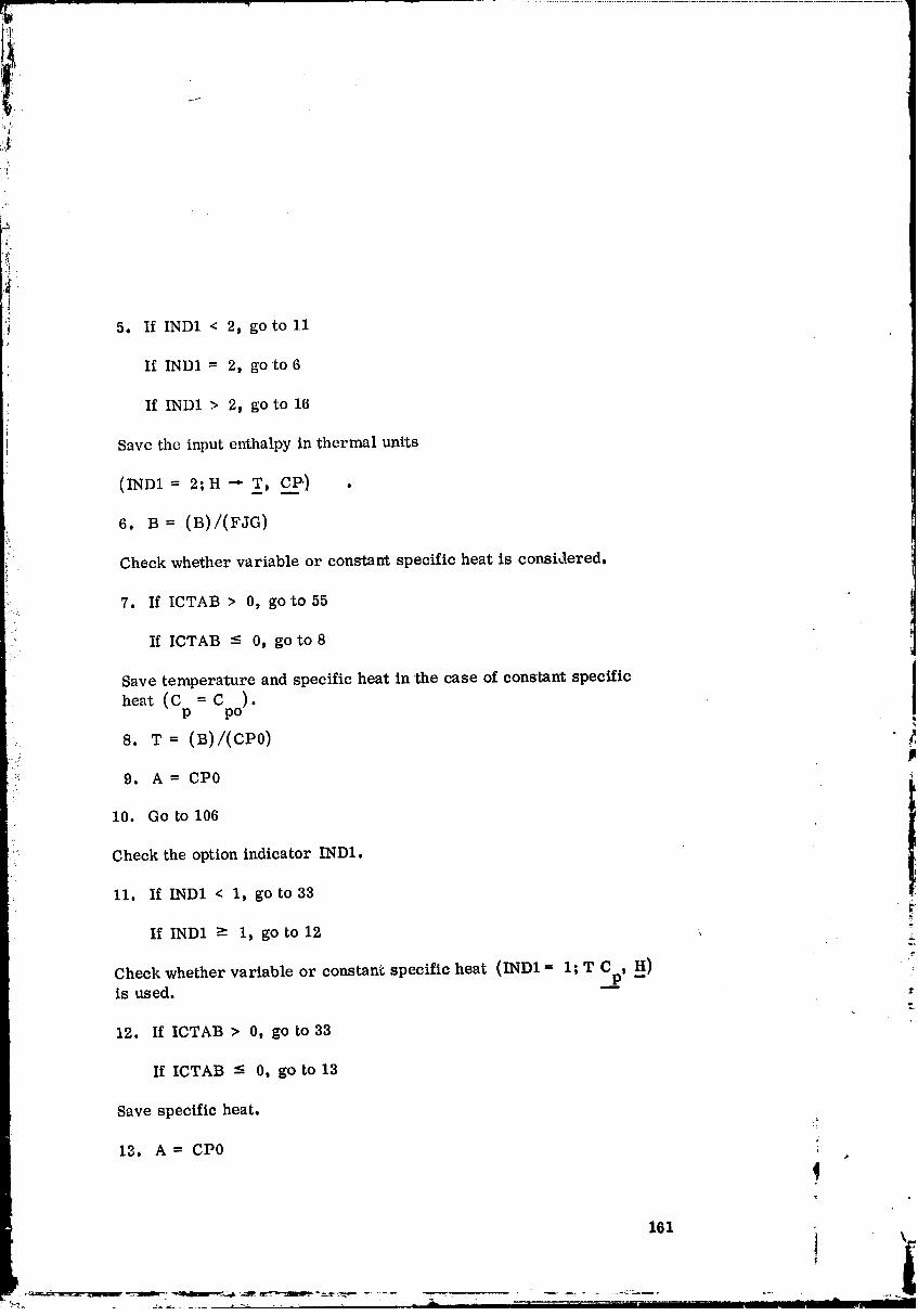
,/
/i
5. If IND1 < 2, go to 11
If IND1 = 2, go to6
If IND1 > 2, go to 16
Save the input enthalpy in thermal units
(IND1 = 2;H-" T, C__P') •
6.B = (B)/(FJG)
'= Check whether variable or constant specific heat is considered.
7. If ICTAB > 0, go to 55
If ICTAB -- 0, go to8
iSave temperature and specific heat in the case of constant specific
heat (Cp = Cpo).
8. W = (B)/(CP0)
::_: 9. A = CP0
I0. Go to 106
h...
( Check the option indicator 1ND1.
11. If IND1 < 1, go to 33
If IND1 >- I, go to 12 ,
Check whether variable or constant specific heat (IND1 -- 1; T Cp, H}is used.
o
12. If ICTAB > 0t go to 33
If ICTAB -_ 0, go to 13
Save specific heat.
13. A = CP0
161 i \!
00000003-TSG05
,_ ................................. ....................................
!
:i
'I
,i
Calculate cnthalpy in work units: (CpogJTc).
14. B = (CJG)(T)
15. Go to 106
Calculate the last 'term in the entropy equation (thermal units).
_" In (IND1- 3; P, S -" T_.). ,
16. PR = {ROJ) (Ln((A)/(POMAX}}}
..... .: Calculate entropy to search the temperature table... , • ....
.: ,. 17. STAB = GAPF(TCTAB(IS), GTAB(IS), BARBI(IS),...... - BARB2(IS), BARB3(IS), DCP(IS))
.' . -t ,
•" i:" Check the values between input entropy and calculated er_tropy above.
: :;:::-!Y'!:- .: 18. If B _- STAB, go to 22
:. :.)i.i ' If B < STABD go to 19• : . ".:. :"
Decrement subscript counter to use next lower table values.... o.
!:(.: : :.:: 19. IS = IS - 1
" ::?::!:ii)i::i Check whether subscript counter is still greater than zero.
•:, ": . ..-
.... 20. If IS -< 0, go to 42
If IS > 0, go to 21
21. Go to 17
Calculate the entropy corresponding to TCTAB(IS + 1).
22. STAB = GAPF(TCTAB(IS + 1), GTAB(IS}, BARBI(IS},
BARB2(IS), BARB3(IS), DCP(IS)}
" ,, ..... | I | -'I _I
00000003-TSG06
J._...
.I
_: Check whether the calculated entropy above exceeds the input entropy?! value.
23. If B < STAB, go 'to 27r
] If B - STAB, goto24
Increment the subscript counter to use the next higher table values.
24. IS = IS + 1
Check whether 'the subscript counter has exceeded the table dimension.
. . 25. If IS _ 20, go to 42
If IS < 20, go to 26
/./" :j Repeat the above search until B < STAB is obtained.L.
• . .. • . .. , . ,. .., ,...
...... : • 26. Go to 22
Cheek the value of IS,• ..- . • . ..
" ' 27. If IS >- NOCTAB or IS - 0, go to 42
. . . ..
If IS < NOCTAB and IS > 0, go to 28
Save values of temperature and entropy.•.,::.. . .
" 28. TTP = TCTAB(IS)• ' i : _./
29. FP = GAPF(TCTAB(IS), GTABCIS), BARBI(IS),
BARB2(IS), BARB3(IS), DCP(IS) )
30. TTPP = TCTAB_IS + I)
31. FPP = STAB
32. Go to 68
163r-"
° _
O0000003-TSG07
Temperature T is checked in the following steps down to 44.
(ram- 0or 1).
33. If T -_ TCTAB(IS), go to 37
If T < TCTAB(IS), go to 34
34. IS = IS - 1I:
35. If IS -_ 0t go to 42
If IS > 0t go to 36
36. Go to 33
37, If T < TCTAB(IS + 1), go to 41
• " If T _- TCTAB(IS + 1)_ go to 38
38, IS" IS + 1
' 39. If IS _- 20j go to 42
i.!:-:_. .If IS < 20, go to 40
40. Go to 37
41. is • 0, goto44If IS -< 0t go to 42
_ Print errors and corresponding values.
42, WRITE IS_ 1ND1, Tp A, B
Stop calculation by calling subroutine QUITS.
43. CALL QUITS
Check whether IS exceeds-NOCTAB.
44. If IS m NOCTABt go to 42
p
If IS < NOCTABm go to 45
164
-'" 00000003-TSG08
I .
i'i
,: Check the indicator for option INI)I.
_i 45. If IND1 < 0, go to 5;3
If IND1 = 0, go to 50
If IND] > 0j go to 46
I:
Set T minus 'tabalatedvalue TCTAB(IS)
(ram= i;T- cP,H) .
46. DELT = T - TCTAB(IS)
Calculateer_thalpyinthermal unitsaccording to'theequationin_ • subroutine BARSET.
:. ':..",: 47. B = HTA_B(IS) + (CPTAB(IS))(DELT)
:" + (0.5)(BCP(IS))(DELT)2 + (CCP(IS))(DELT)3/(3.0)"..
+ (0.25}(DCP(IS}} (DELT} 4:?:::iii::
Save enthalpyin work units....... :.
.... ,. ..
48. B = (B)(FJG)
• . . ..
.... 49. Go to 105
, ."; .....
: :_:'ii:/-" : Calculate entropy in this case (IND1 = 0; T, P --- S) .
:, :/:i:::_ :i_ 50. PR = (ROJ} (Ln((A}/PoMAX}) )
•. Ent, opy:. . . -.
51. B = GAPF(T, GTAB(IS), BARBI(IS), BARB2(IS), BARB3(IS), ;=DCP(IS) )
52. Go to lu6
165
. k..,
00000003-TSG09

+'i
i:_i SinceiT:
:,b
T S R P
ii+ Sc = Gi" + BARB1.Ln, T + BARB2iT + BARB3iT2 + DCP i --3 " .-_ Ln--p ,o
il G i + BARBltLn T + BARB2iT + BARB3IT2 + DC S .,+ I) = P cxp " . ._i! °
I
The pressure P can be obtained, using entropy S and temperature T
in the case of (IND1 = -1; T, S, -- P_.), where B is the inputentropy.
_:,,-. • 53. A = (POMAX) (Exp( (GTAB(IS) + (BARBI (IS))(Ln(T) )
+ (BARB2(IS))(T) + (BARB3(IS))(T)2+ (DCP(IS))(T)S/(3. O) - B)/ROJ))
54. Go to 106
,.. Variable specific heat is considered from 55, when IND1 = 2.
Temperature T and specific heat C are obtained using givenenthalpy H = (B). P
!/!::! (IND1 = 2; S "" T, CP) ]m
Check whether the input enthalpy exceeds HTAB(IS) to search for: •temperature T .e
: : ++i;: 55. If B - HTAB(IS), go to 59
•If B < HTAB(IS), go to 56• +
56. IS = IS - 1r
/:
Check the value of IS.
57. If IS - 0, go 'to 42
If IS > 0, go to 58
166
00000003-TSG10

r!i
;: 58. Go to 55
59. If B < ItTAB(IS + ]), go to_i:l
" S I),; If B ->. ItI.AB(I, + go to G0
60. IS = IS + 1
61. If IS _ 20, go to 42
If IS < 20, go to 62
62. Go to 59
Chock the value of IS.- . :( .
• .: 63. If IS - NOCTAB or IS < 0, go to 42
• .: - If IS < NOCTAB and IS > 0, goto64
' :: :. Determine the table temperature and enthalpy corresponding to IS
• : and IS + 1,
64. TTP = TCTAB( T'_._j
. .: 65. FP = HTAB(IS)• • ::)
:ii:/ ( ): ':: 66 TTPP : TCTAB IS + 1
_ !: :'::: 6,7. Fpr., : HTAB(IS + 1)
.... : Determine the following quantity.t
(J8. IT0 = ((TTP)(FPP - B) - (TTPP)(FP - B))/(FPP - FP)
Check the option indicator IND1.
69. If IND1 > 2, go to 73
167
00000003-TSG 11
%
r! Define DI,_LT (IND] = 2; II-* T, CP).
70. DELT = TT0 - TCTAB(IS)
Compute enthalpy.
71. F0 =:II'I'AB(IS)+ (CPTAB(IS))(I)EI,'I')+ (0.5)(1_C[''(IS))'x (D_L'r)2._ • (CCP_IS)) (_)"Ll_l)a/" (,_'. o)
' + (0.25)(IICP(IS))(111,:I/I')4
72. Go to 74
Compute entropy for IND1 = ,," (P, S -* _T)"
73. F0 = GAPF(TT0,GTAB(IS),BARBI(IS),BARB2(IS),BARB3(IS),DC P(IS))
Determine the temperature.
74. TT1P : ((TT0)(FPP - B) - (TTPP)(F0 - B))/(FPP - F0)
•' . . .:. :;
:'..:: 75. TTIPP = ((TT0)(FP - B) - (TTP)(F0 - B))/(FP - f0) ,I
• - Set switch indicator to minus one.
76. N = -i
• ..: • Save temperature. ,_'
!:1%.=..>.• }.... "" 77. TAU = TT0• ' .:.:: .
_' Save entropy.
78. SF = F0
Check whether the entropy or enthalpy calculated is nearly equal tothe input one, using a tolerance of 10 -_.
79. If I(SF - B)/(B)[ - 10 -?, goto84
If J(SF - B)/(B)[ > 10 -?, go toS0
• .. . ;
168
k.,
00000003-TSG13
Check whether the entropy o"_enthalpy computed is equal to or less
than the input value.
80. If SF -< B, go to86
i.I If SF > B, go to 81
Sot¢
81. TTPP = TAU
: 82. IrPP = SF
83. Go to 88
Save the temperature in case convergence is achieved in step 79.
84. T = TAU
.!85. Go to 103
.... Store temperature and entropy or enthalpy in case convergence is not:: obtained and 'the computed entropy or enthalpy is less than the input
86. TTP = TAU
87. FP = SF
iliI Check 'the switch indicator. _i
88. If N < 0, go to 89 _.
If N = 0, go to 92 "T
If N > 0, go tol01 . _-
Set 'the switch indicator to zero.
89. N=0
Store the tcmpcrature.
169
I i
00000004
:i
TTIP,_ 9(1. TAIl :-:
;I '
i'i !)I. ('O Lo 94
S_,t. N c'CFLalLo one,
92. N :"- ]
( ','; St n'( lc'.nll_craturc TAU.
v93, LAU ----TTIPP
"" (_'ht_ck[_clllport/ture TAU,
94. If TAII :=_-TTP or TAU >- TTPP, go to 88 J• . , .._
• . J
• If TAU > TTP and TAU < TTPP, go to 95 I
ii" :/i I. Check the option indicator IND1.: .?
.....'""'": 95. If INDI <- 2, go to 98
IiIi !-....,.• . ..
,.!..:.;..(..,. If IND1 > 2t go to 96 l
2.'.'- . ".': "
,. i(.;:.,.i," Calculate entropy using temperature TAU, (IND1 = 3; P, S-- T).!.-71_; 96. SI" = GAPF(TAU, GTAB(IS), BARBI(IS), BARB2(IS),' ':"":": BARB3(IS) DC P(IS})
. .".:. "....
• .:"':; ,.. "': _•. :. :......
".:::i_ Ilepeat the iteration.
I" ii.i.":i"i 97. Go to79
Define DE LT to obtain enthalpy at temperature TAU
(LND1 ,: 2; H --* T, C__.PP).
98. I)ELT = TAU - TCTAB(IS)
En thal.py at tempe rature TAU.
99. SI ..... HTAB(IS) + (CPTAB(IS))(DELT)+ (0.5) (BCP(IS))(DELT) 2
+ (CCP(IS))(DELT)3/(3.0) + (0.25)(DCP(IS))(DELT)4
170
00000004-TSA03
:i
i . 100. Go to 79L' . " ' "
Check whether convergence is obtained.
101. If (FPP - FP)/(FP + FPP) > 0.0010, go to 68
If (FPP - FP)/(FP + FPP) -< 0.0010, go'to 102
a_
Calculate the temperature.
• 102. T = ((TTP)(FPP - B) - (TTPP)(FP - B))/(FPP - FP)
Check the option indicator.• . /...!
: :: :i::i:i: 103.If i_01> 2, goto106.'/ .' ,(.
• : _ If IND1 -< 2, go 'to 104
•i•- _: :i:: ': . Compute DELT, (IND1 = 2, S-" T, C__P).
.... ......::_:'_ 104. DELT = T - TCTAB(IS)
.... Compute specific heat at temperature T. II
" _ : : 105. A = CPTAB(IS) + (BCP(IS))(DELT) + (CCP(IS))(DELT) 2: ".:'_'.: . " :,
...... + (DCP(IS}) (DELT) 3• .:...
: :- .i_ ::..... Save the temperature.
: .... : 106. AA = T
...... : Save the specific heat or pressure.
107. BB = A
Check the option indicator.
108. If IND1 = 2, return
If IND1 ¢ 2, go to 109
171
00000004-TSA04
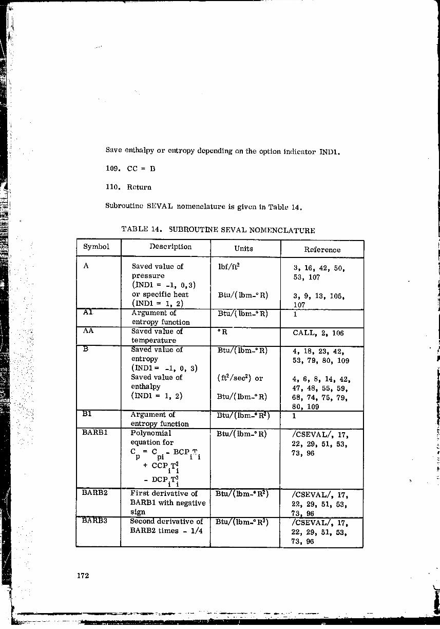
_L
: '_i . .
",,i_
ii
' Save enthalpy or entropy depending on the option indicator IND1.
109. CC = B
_._ 110. Return
Subroutine SEVAL nomenclature is given in Table 14.
i:
TABLE 14. SUBROUTINE SEVAL NOMENCLATURE
Symbol Description Units Reference
.. A Saved value of lbf/ft 2 3, 16, 42, 50,. pressure 53, 107. (.IND1 = -1, 0,3)
or specific heat Btu/(lbm-=R) 3, 9, 13, 105,".. (IND1 = 1, 2) 107 j
...... A1 Argument of Btu/( Ibm- ° R) 1 i-. entropy function
:_'.51{ AA Saved value of °R CALL, 2, 106::i:: temperature
_..:: B Saved value of Btu/(lbm- °R) 4, 18, 23, 42,._:,. ,: entropy 53, 79, 80, 109 P:.:.:.....:: (IND1 = -1, 0, 3)
: _":::i: Saved value of (ft2/sec 2) or 4, 6, 8, 14, 42,
. :".: enthalpy 47, 48, 55, 59,
_: :::(/ !:i (IND1 = 1, 2) Btu/(lbm-°R) 68, 74, 75, 79,.. _":!::...i 80, 109
i: :.:!:.!I B1 Argument of Btu/(lbm-°R 2) 1., entropy function
•_:. ,: BARB1 Polynomial Btu/( lbm-° R) /CSEVAL/, 17, .,:._. ... :. equation for 22, 29, 51, 53,
" C = C - BCP.T. 73, 96p pi z 1 ..:
+ CCPiT _ _
- DCP.T 3. ., =1 1
BARB2 First derivative of Btu/(Ibm-=R _) /CSEVAL/, 17,BARB1 with negative 22, 29, 51, 53,
sign 73 r 96BARB3 Second derivative of Btu/(lbm.°R 3) /CSEVAL], 17,
:. . BARB2 times - 1/4 22, 29, 51, 53,. 73, 96
172
...... ._:.-_ ::_-:.22=::: ::: i " - :_ _ " ;I '0 ill" i....... i i -- / _ "- -
00000004-TSA05
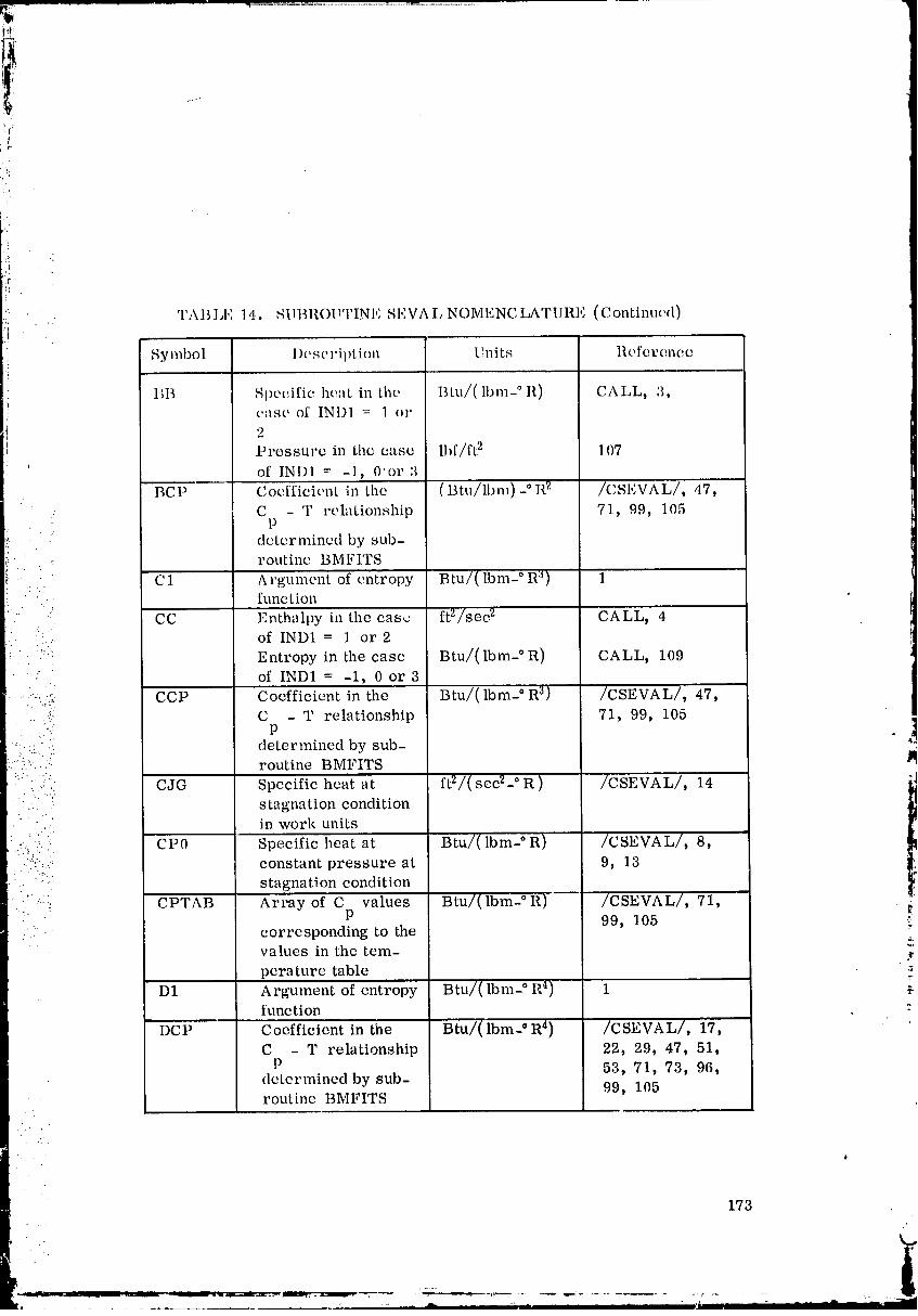
/
'_ TABLI': ]4, _IBROt 1IN , SEVALNOMFNCLATURE (Continued)
:.! Symbol 1)escription Units Reference
BB Si)ecific heat in the Btu/(lbm- ° R) CALL, 3,case' of INDI = I or
2Pressure in tim case lbf/ft 2 107
' of IN1)I = -1, 0'or 3O _ "t'BCP Coefficient in fl_e (Btu/lbm)- II 2 /CSI_VAL/, 47,
C - T relationship 71, 99, 105P
determined by sub-routine BMFITS
... C1 Argument of entropy Btu/(lbm- ° R _) 1. function
CC Enthalpy in the cas.z ft2/sec 2 CALL, 4of IND1 = 1 or 2
:: " "i Entropy in the case Btu/(lbm- ° R) CALL, 109' ' of IND1 = -1, 0 or 3
..-:.i,.,;i CCP Coefficient in the Btu/( Ibm- ° R _) /CSEVAL/, 47,:". .!i: C -T relationship 71, 99, 105
: ./.. p ,!•:,.. " determined by sub- "
,. ".;. : ,:::::?. ". routine BMFITS
::":':'" CJG Specific heat at ft2/( sec2- ° R ) /CSEVAL/, 14;: :::: ' s tagna tion condition
l
, .:: in work units:(.. ::.. CP0 Specific heat at Btu/(lbm- ° R) /CSEVAL/, 8,
•:"":_/:...!_ constant pressure at 9, 13
- "- stagnation condition
!_.":.. .: CPTAB Array of C values Btu/(lbm- ° R) ' /CSEVAL/, 71,P 99, 105
.": • corresponding to the
" values in the tem- .,perature table
D1 Argument of entropy Btu/( Ibm- ° R4) 1 _-func tion -"
DCP Coefficient in the Btu/( lbm-° R 4) /CSEVAL/, 17,C - T relationship 22, 29, 47, 51,P 53, 71, 73, 96,
determined by sub- 99, 105routineBMFITS
:.. . '
173
00000004-TSA06
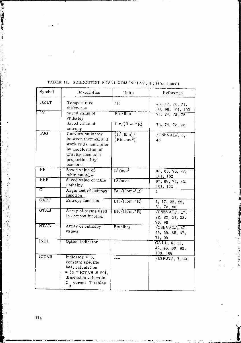
c_
ii
',{ TAB IJ_: !4. SUBROIiTINE SEVA I, NOMENC I,A'I' U,Itl ,,' ( (! ontinued)•il ........
: Symbol Dc'scription Units llcferc,nce
i I)ELT 'l'cmperaturc "11 46, 4'7, 70, 77!i
difference. 98, 99, 704, 105I,'0 Saved w_lui: of Blu_ 71, 74, 75, 78
entha lpy
_ Saved valtl(', of I_l.u/( Ibm- ° I!) 73, 7,:I, 75, 78entropy
FJG Conversion factor (ft2--lbm) / /CSEVAL/, 6,between thermal and (Btu-scc 2) 48work units multiplied
by acceleration ofgravity used as a
proportionalityconstant
FP Saved value of ft2)Jsee 2 65, 68, 75, 87,table enthalpy 101, 102
: FPP Saved value of table ftZ/sec z 67, 68, 74, 82,
.,'/ enthalpy 101, 102: G Argument of entropy Btu/( Ibm- ° R) 1
2:i:!. rune ti on> GAPF Entropy function Btu/(Ibm-°R) 1, 17, 22, 29,::/::::. 51, 73, 96
GTAB Array of terms used Btu/(lbm- ° R) /CSEVAL/, 17,. in entropy function 22, 29, 51, 53,
: 73, 96--:3.
HTAB Array o'f enthalpy Btu/lbm /CSEVAL/, 47,:. values 55, 59, 65, 67,
: 71, 99" IND1 Option indicator CALL, 5, 11,
42, 45, 69, 95,103, 108
ICTAB' Indicator = 0, -- /INPu'r/, 7, 1').constant specificheat calculation
= (3 _ ICTAB _ 20),dimension values inC versus T tables
P
174
,I
.... 00000004-TSA07
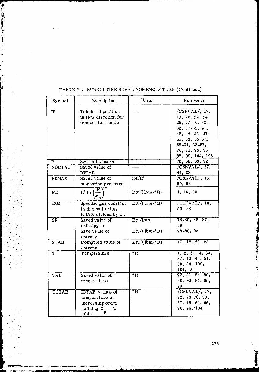
r!l
'i'i
+: TABLie 14. SUBROUTINE SEVA L NOMENC I,ATURE (Continued)"I
Symbol Description Units Reference
IS Tabulated position /CSLVAL/, 17,
in flow direction for 19, 20, 22, 24,
teml)erature table 25, 27-30, 33-35, 37-39, 41,
': 42, 44, 46, 47,51, 53, 55-57,59-61, 63-67,
70, 71, 73, 96,
98, 99, 104, 105i
N Switch indicator -- 76, 88, 89, 92: . NOCTAB Saved value of -- /CSEVAL/, 27,
• ICTAB 44, 63• .. DOMAX Saved value of !bf/ft 2 /CSEVAL/, 16,
stagnation pressure 50, 53;"., , .-
• +.. PR R' In Btu/(lbm-°R) 1, 16, 50
. _ . :+ ROJ Specific gas constant Btu/(lbm- ° R) " /CSEVAL/, 16,
_!._..:.:';.i. in thermal units, 50, 53 ,...,!
...... RBAR divided by FJ I_::" : SF Saved value of Btu/lbm 78-80, 82, 87,
. +::. +. enthalpyor 99..: Save v_lue of Btu/( lbm-° R) 78-80, 96
+. :: ..... entropy.:...:_.'" : '
.:...:!..• -:: STAB Computed value of Btu/(lbm-°R) 17, 18, 22, 23::";:." _.. entropy;. ,- ,:,
....+.... T Temperature °R 1, 2, 8, 14, 33,+. " ': 37, 42, 46, 51, _:
53, 84, 102, ,_104, 106
O .::TAU Saved value of R 77, 81, 84, 86,
temperature 90, 93, 94, 96, +98 :+
Tt'TAB ICTAB values of °R /CSEVAL/, 17,
temperature in 22, 28-30, 33,increasing order 37, 46, 64, 66,
defining C - T 70, 98, 104table P
175
.............. ...... .+__
00000004-TSA08

Fr._
J
i"
176
• 1
00000004-TSA09
i
! SUBROUTINE START
Subroutine START locates the sonic point (M = I) from the input Maehnumber versus x table and then computes initial values for momentum and
i energy thicknesses.
The table of Much numbers is first scanned to locate an exact inputvalue of M = 1.. If none is fotmd, the sonic point location is determined fromtke following iteration procedure.
1. Locate the i th interval, in the table, which contains M = 1,andassmue x =x..
g 1
: 2. Using subroutine XNTERP. evaluate M at x• g g
• ' 3. Make a tolerance comparison.
..... ':_. It' ]M - 1.Ol <- TOLZME, convergence is satisfactory,g
and appropriate flow quantities are avaluated at x . If
:":::::"::::.. outsid_ the tolerance, a secant method is used to make
:,:. : another assumption for x and steps 2 to 3 are repga_d ]g _1
up to a maximum of 50 iterations. $
...... -. Using the flow quantities just computed., subroutine INTZET is used
• . :.i to evaluate integrals 11 and 12 for _ = 1 The shape factor 5*/0 i_ then• _ .. : :. evaluated from equation (125) [ 1]. An iteration for the skin friction coefficient
::".:......• . C£ is performed (similar to that in subr(,_tine BARPRO ), and a value of
• :_: ::!_: momentum thickness 0 is computed. These values are assumed to be the
_. "":' i'..i, initial values for 0 and _ at x . i_.... .7- g
• . .. .
COMMON BLOCKS #'
COMMON blocksCOFIIF, CSEVAL, INPUT, INTER,LOOKUP, OUTI_UT, SAVED, and TABLES are used• _ -"
TBL SUBROUTINES
Subroutine BARCON calls START.
. . START calls CFEVAL, GETPT, INTZET, QUITS,:' .:" SEVAL, and XNTERP.
%,
• " . 177
00000004-TSA10
'_i ' FORTIUkN SYSTEM ROUTINES
FORT1L_N library routine SQRT is used.
Built-in F()R'rlL_N ftmclion ABS is used.
CA LLING SEQU ENC E
': The subroutinocallingsequencc is:
CA LL START
SOLUTION METItOD
Set table position indicators for a first time
, . : entry indication.
--. 1. IMX =-1.. . .:.
'- .-. 2. IYS = -1,-:. :...,
..... 3, ITWX = .-1
::_;.... :., Initialize subscript counter to zero.
: .... ::: 4. I = 0
Increment subscript counter.
-.::: " .:: 5. I = I + 1- ." .-,...F.
...:.' ' " Check whether Much number table includes M = t. 0.
6. If ZMTAB(I) < 1.0, go to 7
If ZMTAB(I)= 1.0, go to 10
If ZMTAB(I) > 1.0, go to 13
Check whether subscript counter is equal to the table dimension.
.'. ,_
' ":_' i "
1'/8
I!
00000004-TSA11
'i
7. If I < /XTAB, go to 5
If I _ IXTAB, go to 8
The Mach nunlber ttii)le does not conta_i!! _! : 1.0 .
_. WRITE error message about Much number table
Print out all the COMMON blocks and go to next case.
9. CALL QUITS
t.
: Obtain axial distance at which M = 1.0.
.... 10. X = XITAB(I).i
• - Set subscript counter for the Mach number that just exceeds one.
, 11. IBEG = I + 1•.:-.....:. ,'..
• _:..: 12. Go to 29
:::ii.)" !: i-:. Check whether the first Mach number table value is greater than one.•:, • .. ) ..., . -.
: :": "_ 13. If I --- 1, go to 8
.:.'.i '-:j); If I > t, go to 14
" "'-.._:,5 :'_i:- ' .:_:i).,: Save value of axial distance at which Math number becomes greater
: i! " :: ) .(: than one., , . ...
."?. :i. ;. 14. XG = XITAB(I)
Obtain the lowest number table value greater than one.
15. ZME = ZMTAB(D
Approximate the axial distance at which M = 1.0.
: 16. X = XITAB(I-1) + (XITAB(I) -XITAB(I-1))/
:i...' (ZMTAB(I) - ZMTAB(I - I))(1.0 - ZMTAB(I - 1))• .: ,... -
" Initialize Mach number iteration counter to zero.•: :(
i
* 17. J= 0
Set subscript counter for which Mach ntuuber exceeds one.
18. IBEG = I
Imcr_ment Macb number iteration counter_
19. J=J+l
.!.
Save previous value of axial distance at which M > 1.0.
-- ._. 20. XO = XG
::: Save previous value of Mach number obtained from table lookup.
_: 21. ZMO = ZME." . -.
Save present value of axial distance for which M > 1.0 .... "._,..;
' i'. 22. XG = X ',1:......'"
:_i: _.:-. Determine value of Mach number for approximated value of axial ._• .-.-. :.
:_:: :: distance.. . .;...',
:i 23. CALL XNTERP(X t ZM____E_ZMEP_, IMX, XITAB t ZMTABp IXTAB,
• c x, IMx} _
• -:....,_, Check whether the _ falls within the desired tolerance "
: .ii: _:: band.
i )): 24. If JZME - 1.0] -<. TOLCFA, goto 29
i If JZME - 1.0] > TOLCFA , go to 25 _
Compute a new value of the Mach number. . ;
25. ZMX = (XG- XO)/(ZME - ZMO)
Compute a new value of the axial distance.
180
O0000004-TSC01
26. X = XO + (1,0 ZMO)(ZMX)
Check whether there have been more thin1 50 iterations to determine
the Maeh nmnber equal to one.
27. If J := 50, goto 19
'; If J > 50, go to 28
There have been more than 50 iterations on the Mach number.
28. WRITE error message about Math number iteration failure
Determine the value of Much nmnber at final value of axial distance.
• 29. CALL XNTERP (X, ZME, ZME____P,IMX, XITAB, ZMTAB, IXTAB,
. .. CMX, IIVlX)
Determine the nozzle radius at this value of axial distance.• .".h •
;:..: 30. CALL XNTERP (X, YR, YR_____P,IYS, XITA.B, YITAB, IXTAB,' i._='.:, CYX, IMX) m:..,. .... _7
""' '. - Compute the pressure and temperature for the computed Much number, i_
• ." 31. CALL GETPT (ZME, PSE, TE)
, Compute the enthalpy and specific heat at this temperature.
::. .. .>.
.......,.. 32. CALL SEVAL (i, TE_ CPE, HE)..
Compute the ratio of specific heats. _.
33. GAME = (CPE)/(CPE - (RBAR)/(FJ))
Compute the difference between stagnation and static enthalpy.
34. HB = ttO - HEi
Compute the fluid velocity,
. . 181 _ i,
00000004-T8002
!
35. UE = SQRT((2.0)(HB})
Compute the fluid density.
36. RHSE = (PSE)/(TE)/(RBAR)
Compute viscosity at the static telnperature.
ZMVIS37. ZMU = (ZMU0}((WE)/CT0})
Compute the adiabatic wall enthalpy.
'5. 38. HAW = HE + ((PRANDT) )(HB)
.. . .-
....." Compute the adiabatic wall temperature and specific heat.
39. CALL SEVAL(2, TA._W, CPAW, HAW}
Check for temperature option to be used.
.::-::::y::":.:,. 40. If ITWTAB < 0, go to 41 '4
-_.. ......:.4 .
........... .... If ITWTAB = 0, go to 44•. '. . ....- .-.. . .
•!..... • .!'
...:: :.:. If ITWTAB > 0, go to 47
::: :'( :: . Adiabatic wall temperature option is used; set wall enthalpy and wall
•?;:!!:)i:ii:,:i::._ temperature to adiabatic values.
., _, 41. HW = HAW
...:. :.
42. TW = TAW
43. Go to 49 r
Constant wall temperature option is used; set wall enthalpy to previously "-
computed value.
44. HW = TWTAB(2)
Set wall temperature to input value..:.. . "."
00000004-TSC03

46. Go to 49
'l"'JJm[ar wall opti_n is ttsed; determine the value of wall temperature.
47, CAI,I, XN'II_:L{P(X, ']'__WW,'i_'WI____, ITWX, XI'I'AB, 'rW'rA]_, mTA]:_,, c"rw>', ]Mx.)
Compute enLlm.lpy "rod specJ[ic heal at Lhe wall Lemperature.
48. CALlJ SEVAL( I, TW, CP\______,II____W)
Obtain flow properties to evaluate integrals I t and 12 .
i'. 49. AFINT = HW
::. 50. BFINT = H0 - HW I
I.... ':'.:_::_ 51. CFINT = - HB
'!: 52. TFINT TE i
"""' /: 53. MMINT = MZETA
• Set indicator to evaluate first integral 11 .
..':.;_ :..".:
• /U:. 54. IFINT = 1•.h:
Evaluate first integral It .
55. CALL INTZET( 0. 0, 1.0, ZI1)
Set indicator to evaluate second integral I_..d,
56. IFINT = 2
Evaluate second integral 12 .
57. CALL INTZET( 0. 0, 1.0, ZI2)
Compute the boundary layer shape factor.
!
183
00000004-TS004
58. I)ELSOT - ((1,0)/(ZhiZETA) - ZI2)/(ZIi)
Cheek for type of flow to be considered.
59. If EPSZ = 0.0t go to62
If EPSZ ¢ 0.0, go to 60i:
Axisymmetrie flow is considered; set inte, rmediate term to ratio of
nozzle radius slope to tile nozzle radius.
, 60. ERASE5 = (YRP)/(YR)
61. Go to 63
Two-dimensional flow is considered; set intermediate term to one.." . .-.
: 62. ERASE5 = 1.0
..... . Compute intermediate term.
:,,:::"::;. 63. ERASE4 = (1.0 + DELSOT)/(1.0 + (GAME - 1.0)/(2.0))(ZMEP)i. /-:;/ ,::'- + ERASE 5 P
":..... ':: Cheek on value of intermediate term.
:.::".:.!:: 64. If ERASE4 ¢ 0.0, go to 66
.. ".91 If ERASE4 = 0.0, go to 65
_ The intermediate term is in error. .._.'...
65. WRITE error message and possible remedyT
Compute ratio of difference between stagnation and adiabatic wall ,.temperature to the adiabatic wall temperat.ure.
66. E1UKSE1 = (17.20) (TO - TAW}/(TAW}
- Compute ratio of difference between static and stagnation temperatureto adiabatic wall temperature.
" Z" . .
184•" .. .
00000004-TSC05

i ::
'/
_:i 67. ERASE2 = (305.0)(TE - T0)/(TAW)
Compute term for calculating the momentum thickness.
68. CTHET = (0.50)(SQRT(1.0 + YRP2))/(ERASE4)
Compute skin friction coefficient intermediate term.D:
59. CRT2 -- ((TAW)/(TE)) (1" 0-ZMVIS) (RHSE)(UE)/
( (ZMU) (CTHET}
Compute ratio of adiabatic wall temperature to the static temperature.
" ' (TAW)/(TE)• _.. 70. ERASE3 =
• .::_ Set initial assumption for the skin friction coefficient.
• ' 71, CFA = 0,0010
'_: ::"_ Initialize skin friction coefficient iteration counter to zero.
i/_i:=::...:... 72. JE = 0
':.._... :-_.!, Increment skin friction coefficient iteration counter. 1
:..' : 73. JE = JE + 1
:"!:/.. i Save previous skin friction coefficient quantity" .i!: '" •
_. 74. CFG = CFA ii....' ,,
z_
" : Compute momentum thickness based on computed skin frictioncoefficient. :_
75. THETA = (CFC,)(CTHET)
Compute term for obtaining skin friction coefficient based on Coles vrelationship.
76. CR = (CRT2)(TItETA) 2
185
00000004-TSC06
:i,i•:!
-t_ .'_i _
}! Compute skin friction coefficient based on Coles' relationship.
77, CFB = CFEVAL(CR)
Compute intermediate term.
78. TTAW _- 1.0+ (ERASE1)(SQRT((CFB)/(2.0))* + (ERASE2) (CFB)/(2.0)
Check value of intermediate term.
:; 79. If TTAW > 0.0, go to 86
:: If TTAW - 0.0, go to 80
: i Compute new value of the skin friction coefficient,• [. •
: 80. CFA = (3.0)(CFG)
i:, Save_computed value of skin friction coefficient.".
=!:, 81. Z4 = CFA
!://!: pi:ii-.. Save approximation value of skin friction coefficient,
82. Z2 = CFG
::.', Check whether there ha_e been over 50 inte.vations to determine the' ..'.
skin friction coefficient.
i. 83. If JE - 50, go to 73 ,_,
If JE > 50, go to 84 ._
There have been more than 50 iterations on the skin frictioncoefficient.
84. WRITE error message about skin friction coefficient iterationfailure.
85. Go to 96
186
00000004-TSC07
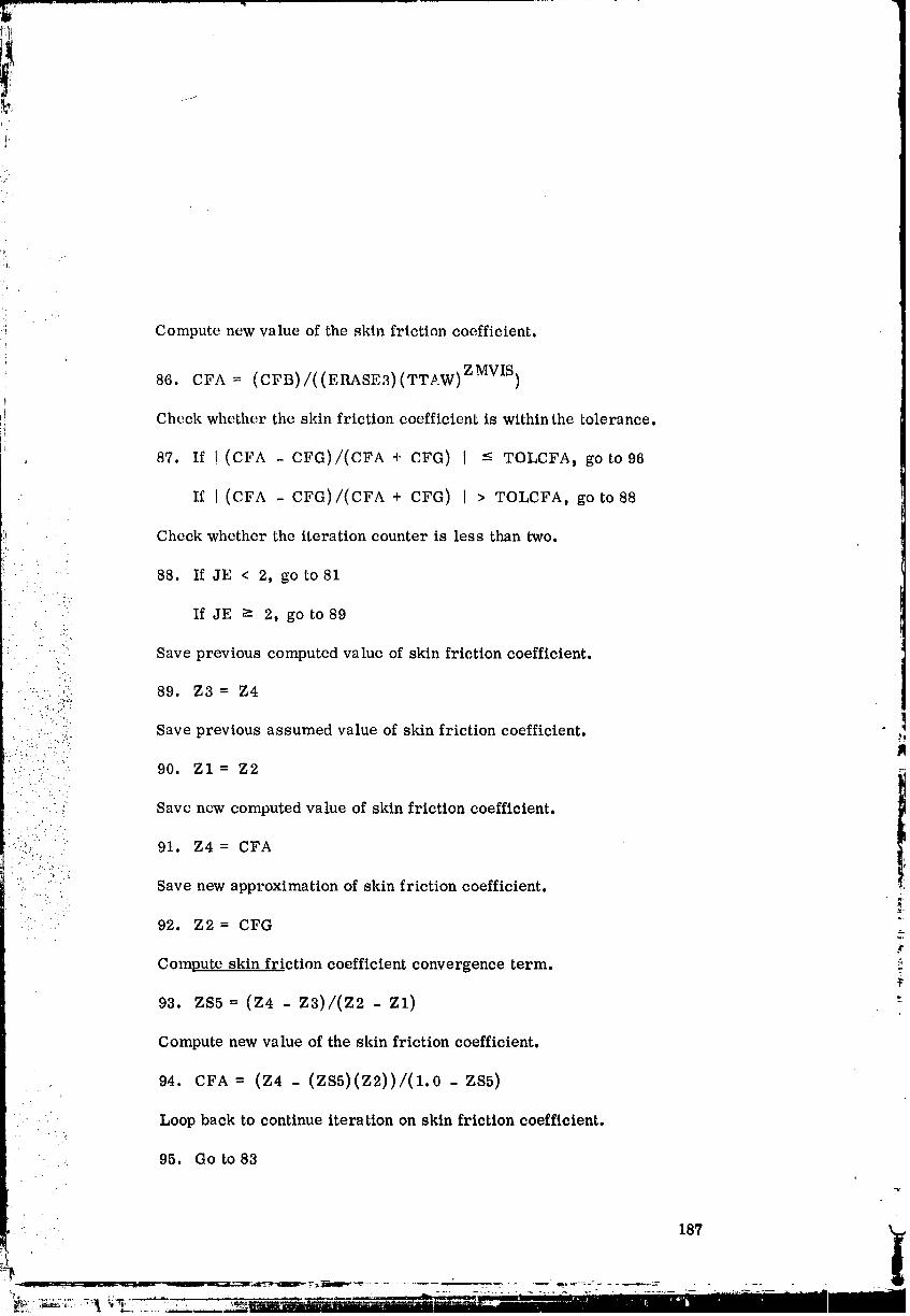
i
Compute new value of the skin friction coefficient.
[ 86. CFA = (CFB)/((ERASE3)(TTAW) ZMVIS)
Check whether the skin friction coefficient is within the tolerance.
, 87. If !(CFA - CFfi)/(CFA + CFG) I -< TOLCFA, go to 96
If I (CFA - CFG)/(CFA + CFG) I > TOLCFA, go to 88
Check whether the iteration counter is less than two.
88. If JE < 2, go to 81
. (.:
: : If JE -> 2, go to 89• .?.:
"." " "L"
Save previous computed value of skin friction coefficient.
.....:,_. :_' 89. Z3 = Z4
• ., " Save previous assumed value of skin friction coefficient...... i..::. _,
.. :' 90. Z1 = Z2'. ..:,. -.
: ....- . ..• . ..,
.... ,-_ Save new computed value of skin friction coefficient.
: _ 91. Z4 = CFA:"-'::: ...
' ". -_.. A- • "
.... Save new approximation of skin friction coefficient.
92. Z2 = CFG 2.,r
Compute skin friction coefficient convergence term. ..
93. zs5 =(z4 - z3)/(z2 - zl) "-
computenew value of the skin friction coefficient.
94. CFA = (Z4 - (ZS5)(Z2))/(1.0 - ZS5)
Loop back to continue iteration on skin friction coefficient.." . _ .
95, Go to 83
187 . i
O0000004-TSC08
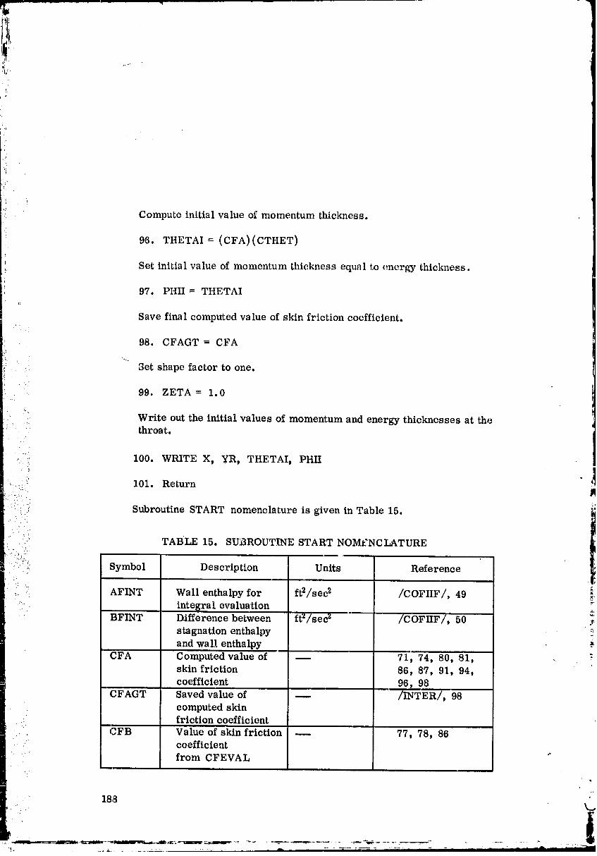
i!II
,_ Compute initial value of momentum thickness.
96. TtiETAI = (CFA)(CTHET)
I Set initial value of momentum thickness equal to energy thickness,
t 97. PHII= THETAIf:
Save final computed value of skin friction coefficient.
98. CFAGT = CFA
.... Set shape factor to one.
99. ZETA = 1.0
Write out the initial values of momentum and energy thicknesses at the:: :' throat.
•i_':: 100. WRITE X, yR, THETAIt PHII
•.._ 101. Return
::: .. ,, Subroutine START nomenclature is given in Table 15. "_
1
".:!' TABLE 15. SUBROUTINE START NOMI::NCLATURE...: .:_. :.'.
::::i:_!::!: Symbol Description Units Reference
_. AFINT Wall enthalpy for ft2/sed /COFIIF/, 49 _.... integral evaluation
BFINT Difference between ft_/sec z /COFIIF/, 50 _'stagnation enthalpy
and wall enthalpy
CFA Computed value of 71, 74t 80, 81, ,.skin friction 86, 87, 91, 94,coefficient 96, 98
CFAGT Saved value of _ /INTER/, 98computed skinfriction coefficient ,
• .. CFB Value of skin friction _ 77, 78, 86coefficient
from CFEVAL
00000004-TSC09
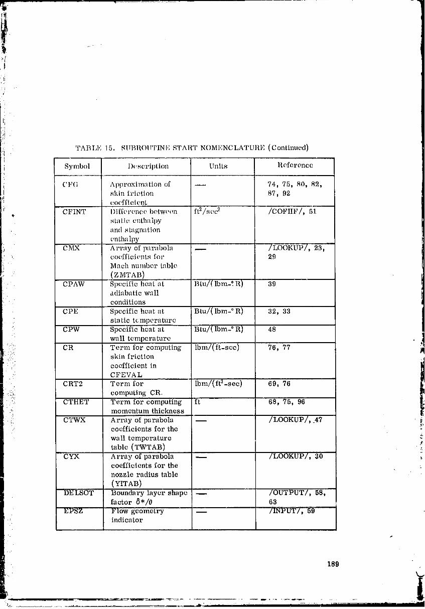
-7
:if
5_
:i TABLE 15. SUBROU'rINI,: START NOMENCLATURE (Continued)
i Symbol I)cscription Units Reference
CFG Al)l)roximation of m 74, 75, 80, 82,t skin friction 87, 92
el coefficient
i ...... CFINT 1)ifferenee between ft2/see 2 /COFIIF/, 51q:
s ta tic c ntha Ipy
and s ta gn'_ tion
entha lpy
- CMX Array of parid)ola -- /LOOKUP/, 23,coefficients for 29Mach number table
:: (ZMTAB)CPAW Specific heat at Btu/( Ibm-? R) 39
adiabatic wall
conditions
CPE Specific heat at Btu/(lbm- ° R) 32, 33
static temperature.: CPW Specific heat at Btu/( Ibm- ° R) 48
wa 11 tempera ture
- CR Term for computing lbm/(ft-sec) 76, 77 ]I:::::_': sldn friction
..,'-
. coefficient in
'. CFEVAL
CRT2 Term for ibm/(ft3-sec) 69, 76• :. computing CR.. : ...:.::
' CTHET Term for computing ft 68, 75, 96
I."ii momentum thickness_. CTWX Array of parabola -- /LOOKUP/, _47• coefficients for the
• wall temperatureY
table (TWTAB) .-.CYX Array of parabola _ /LOOKUP/, 30
coefficients for the
nozzle radius table
(YITAB)
DELSOT Boundary layer shape i /OUTPUT/, 58,factor 5*/0 63
EPSZ Flow geometry -- /INPUT/, 59•._ indicator
189
¥. . I
O0000004-TSCIO
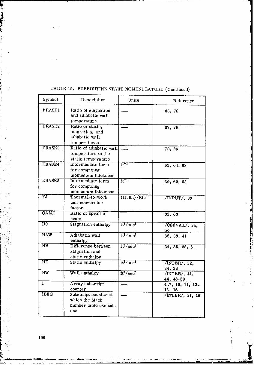
TABLE 15. SUBROUTINE START NOMENCLATURE (Continued)
Symbol Description Units Reference
ERASE] Ratio of stagnation _ 66, 78and adiabatic wall
tempera ture
, ERASE2 Ratio of static, _ 67, 78stagnation, andadiabatic wall
tempera tures
ERASE3 Ratio of adiabatic wall -- 70, 86temperature to the
" static temperature
• ERASE4 Intermediate term ft -1 63, 64, 68for computingmomentum thickness
_. : ERASE5 Intermediate term ft -1 60t 62, 63for computingmomentum thielmess
'-, FJ Thermal-to-wo:,k (ft-l'bf)/Btu /INPUT/, 33unit conversion
' ::: factor
:::::?: GA E Ratioofspecific -- 33t 63_ m
•. :. ::. heats•. H0 Stagnation enthalpy ft'_/sec z /CSEVAL/, 34,
50
. .i:!(_:,.i( HAW Adiabatic wall ft2/sec 2 38, 39, 41entha lpy
HB Difference between ft'Z/sec 2 34, 35, 38, 51_. stagnation and-:. static enthalpy . '
HE Static enthalpy ft2/sec 2 /INTER/, 32, ':34, 38 :,
HW Wall enthalpy ft"/sec z /INTER/, 41,44, 48-50 :"
I Array subscript -- 4-7, 10, 11, 13-
counter 16 _ 18IBEG Subscript counter at -- /INTER/, 11, 18
which the Mach
number table exceeds .,one
I
190
O0000004-TSC 11
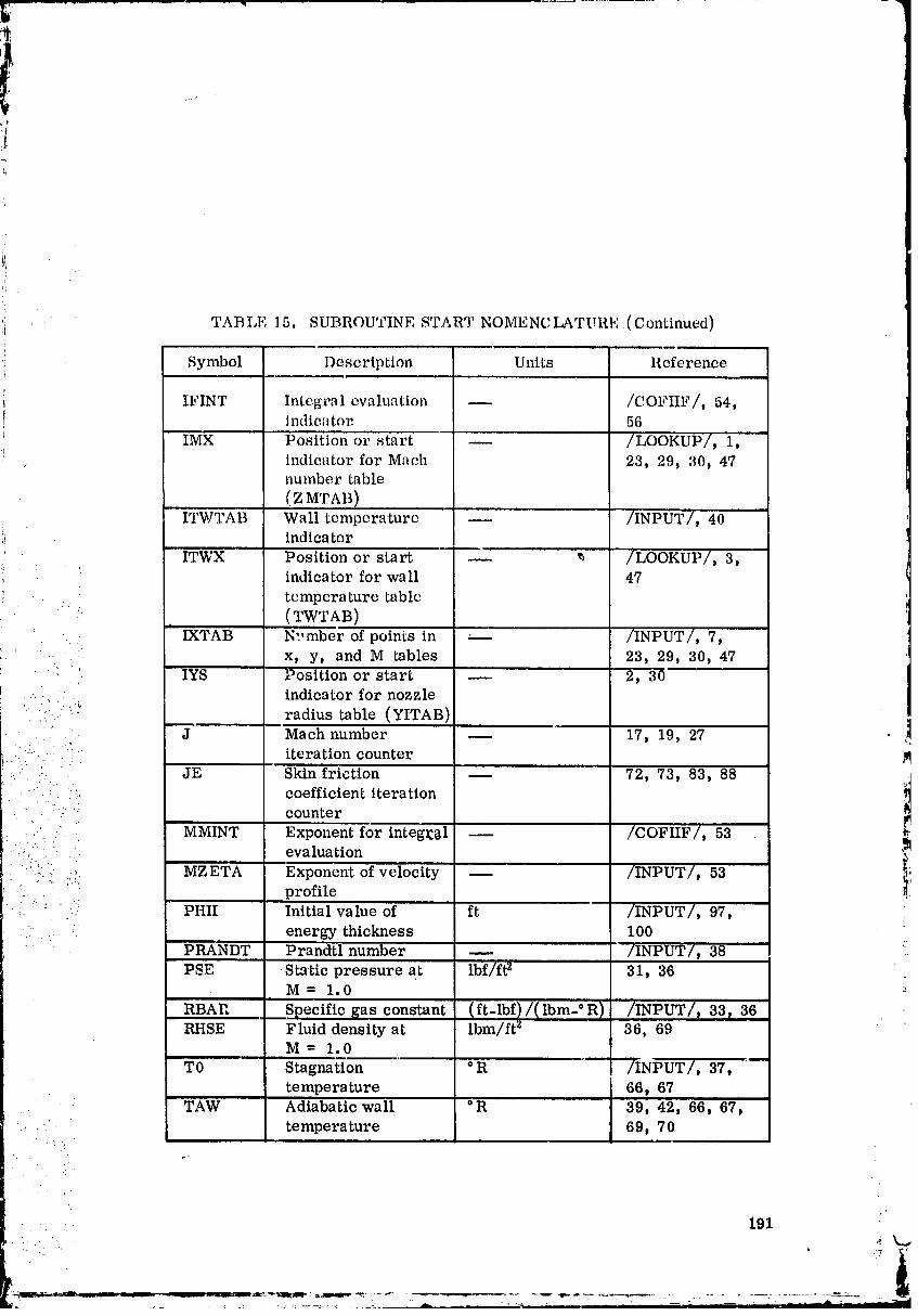
r
l ..,
?
[
• ' T':i " TABLE 15. SUBROUTINE SrAR_ NOMENCLATURE(Continued)i
". Symbol Description Units Reference
IFINT Integral evaluation _ /COFIIF/, 54,indica tot 56
IMX Position or start -- /LOOKUP/, 1,, indicator for Maeh 23, 29, 30, 47
number table
(ZMTAB)
ITWTAB Wall temperature m /INPUT], 40indicator
ITWX Position or start m *. /LOOKUP/, 3,indicator for wall 47
tempera ture table
:": (TWTAB)I
' - IXTAB N'.,mberof pointsin --- /INPUT/, 7,
-. " ,' x, y, and M tables 23, 29, 30, 47IYS Position or start -- 2, 30
...... : indicator for nozzle•, %,
radius table (YITAB)
.. J Mach number m 17, 19, 27 !.L...: " iteration counter_,. • . .
:..:....:. JE Skin'friction -- 72, 73, 83, 88 ._J• " " ':, coefficient iteration !t• , ..' .,
• • : '" counter
[" MMINT Exponent for integ!:_al _ /COFIIF/_ 53• " evaluation '_
_::/_"?. :_. :. MZETA Exponent of velocity -- /INPUT/, 53 i_,'".:: . . . profile
_. :.:... PHII Initial value of ft /INPUT/, 97, .
.... • :. energy-thickness 100
PRANDT Prandtl number -- /INPUT/, 38 ":PSE .Static pressure at lbf/ft _ 31, 36
M= 1.0
RBAI", Specific _as constant (ft-lbf l/(lbm-°R) /INPUT/, 33, 36RHSE Fluid density at lbm/ft z 36, 69
M= 1.0
TO Stagna(ion ° R /INPUT/, 37,temperature 66, 67
TAW Adiabatic wall °R 39, 42, 66, 67,.. - temperature 69, 70. , .. •
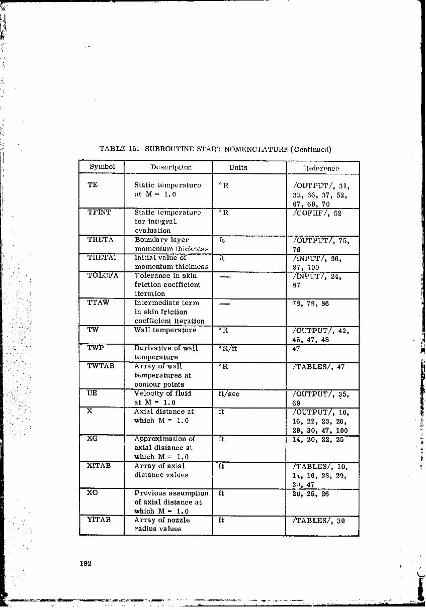
TABLE 15. SUBROUTINE START NOMENCI2_TURE (Continued)
Symbol Description Units Reference
TE Static temperature ° R /OUTPUT/, 31,
at M = 1.0 32, 36, 37, 52,! 67, 69, 70
, TFINT Static temperature ° R /COFIIF/, 52for integral_eva lua ,ion
THETA Boundary layer ft /OUTPUT/, 75,momentum thickness 76
THETAI Initial value of ft /INPUT/, 96,momentum •thickness 97, 100
:- TOLCFA Tolerance in skin -- /INPUT/, 24,friction coefficient 87
• -' iteration
-/... TTAW Intermediate term -- 78, 79, 86• in skin friction
....._.... • coefficient iteration
i'(_:_-} TW Wall temperature ° R /OUTPUT/, 42,
- _."::i: 45, 47, 48 :_':'":.-. '.::"' TWP Derivative of wall ° R/f, 47
•. temperature _.i.........
::, ..:.:.-.:. TWTAB Array of wall ° R /TABLES/, 47 _i....- temperatures at
I
• _ contour pointsUE Velocity of fluid ft/sec /OUTPUT/, 35,
•..:::... .
_-.....:,:...:... at M = 1.0 69.:- " .:" X Axial distance at ft /OUTPUT/, 10, .
_. ......: ." which M = 1.0 16, 22, 23, 26, _'
- . 29, 30, 47, 100
XG Approximation of ft 14, 20, 22, 25axial distance at
which M = 1.0XITAB Array of axial ft /TABLES/, 10, :-
distance values 1,i, 16, _3_ 29,3',), 47
XO Previous assumption ft 20, 25, 26of axial distance at
which M= 1.0i
YITAB Array of nozzle ft /TABLES/, 30radius values
L.
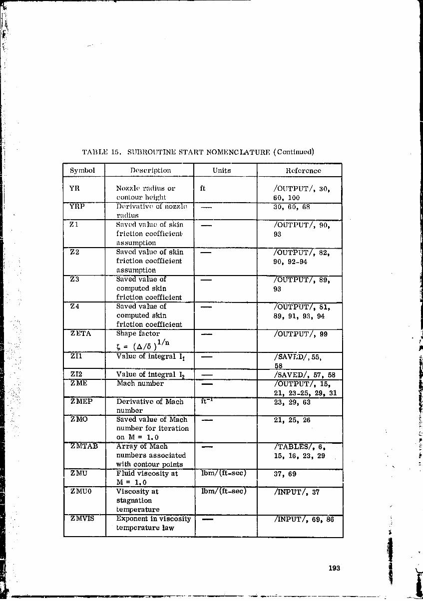
t:
,)
TABLE 1.5. SUBROUTINE START NOMENCLATURE (Continued)
Symbol Description Units Reference
] YR Nozzle r'ldius or ft /OUTPUT/, 30,i contour height 60, 100
--YRP Deriwltive of nozzle 30, 60, 68': radius
Z 1 Saved value of skin /OUTPUT/) 90,friction coefficient. 93
assumption
Z2 Saved value of skin -- -/OUTPUT/, 82,friction coefficient 90, 92-94assumption
Z3 Saved value of /OUTPUT/, 89,
• . computed skin 93- . friction coefficient
I I
• • Z4 Saved value of -- /OUTPUT/, 81,
computed skin 89, 91, 93, 94.:,
• friction coefficient
• " ZETA Shape factor -- /OUTPUT/, 99 1
..... ':.... _ = 1In F,
:il.".:.i:. ZI1 ' Value of integral I i /SAVt';D/, 55, _._'. 58
". _ ZI2 Value of integral I_ -- /SAVED/, 57, 58. ZME Mach number -- /OUTPUT/, 15,
.:..s:: 21, 23-25, 29, 31 l_..:.i:ii_!_ ZMEP ' Derivative of Mach ft .i 23, 29, 63.... number
:: " ZMO Saved value of Mach 21, 25, 26" number for iteration _•
ohM= 1.0, i
ZMTAB Array of Mach -- /TABLES/, 6, _Tnumbers associated 15, 16, 23) 29 ._with contour points . *-
|
ZMU Fluid viscosity at lbm/(ft-sec) 37, 69M= 1.0
Z MU0 Viscosity at Ibm/(ft-sec) /INPUT/, 37stagnation
temperature '"
ZMVIS Exponent in viscosity /INPUT/, 69, 86 :itemperature law
• 193 I
00000004-TSD02

i
"i
TABLE 15. SUBROUTINE START NOMENCLATURE (Concluded)
'! Symbol Description Units Reference
ZMX Computed value of -- 25, 26Mach number initeration on M = 1.0
,_ - ZMZETA Real value of _ /INTER/, 58velocity profileexponent
ZS5 Ratio of difference -- 93, 94
between computedvalues of skinfriction coefficient
and approximations
•. . ......_
. "?.-.:.. ,
.. "-- ..• . . . ..:
..- . _
i".: ..,
-".. ,. .:
194
O0000004-TSDOg
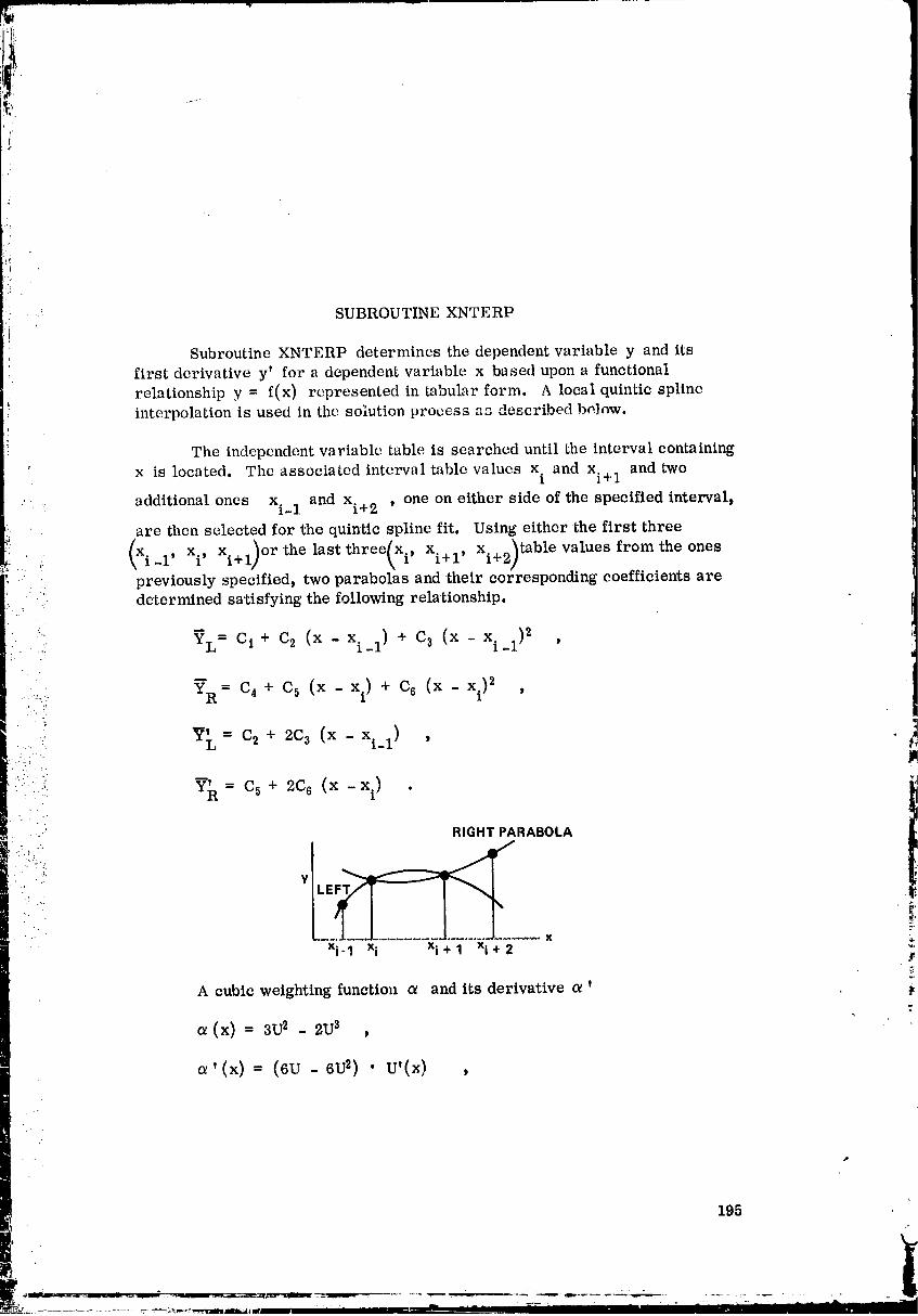
' ! . .i SUBROUTINE XNTERP
Subroutine XNTERP determines the dependent variable y and its
" first derivative y' for a dependent variable x based upon a functional
relationship y = f(x) represented in tabular form. A local quintic spline
interpolation is used in the solution process a_ described below.
The independent variable table is searched until the interval containing
' x is located. The associated intervaltable values xi and xi+ 1 and two
.: additional ones xi_ 1 and xi+ 2 , one on either side of the specified interval,
are then selected for 'the quirttic spline fit. Using either the first three
....: (Xi_l, xi ' Xi+l)or the las.tthree_xi, Xi+l, xi+2)table values fromthe onespreviously specified, two parabolas and their corresponding coefficients are
• ' determined satisfying the following relationship.
" "' _L = C i + C2 (x - X._l ) + C 3 (x - X._l )2" ,:; 1 1 J
_. _= c, + c5 (x - xi) + c6 (x - xi)2 ,
......_: Y_,= c2+ 2c3(x - xi_1) ,
-: __.,,. y = C 5 + 2C 6 (x - ) •
1
• L ":"'
"- RIGHT PARABOLA
..-..
' "' Y E .
xi-1 xi Xi+l xi+2
A cubic weighting function a and its derivative a,
a(x) = 3U2 - 2U 3 ,
-, (_) = (6u - 6u_)• u'(x) ,
195
O0000004-TSD04
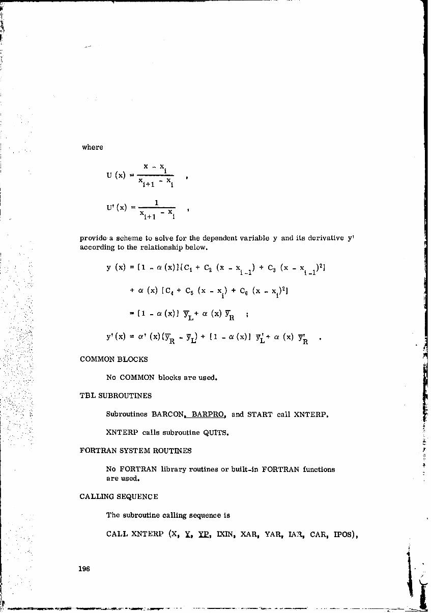
. where
X - X iu (×) =
xi+ 1 - xi
U' (x) = 1xi+ 1 - x i '
CALLING SEQUENCE
.... The subroutine calling sequence is
CALL XNTERP (X, Y, YP, IXIN, XAR, YAR, IA:.R,CAR t IPOS),
196• . 2
O0000004-TSD05
j..
!.
).
,i
_i • where
_. X = input value of the independent variable
Y = output value of the corresponding dependent variable
YP = der:iwttive of the dependent variable
IXIN = table position or start indicator
• XAR = input array of independent variables
:, .... :! YAR = input array of dependent variables
."" ..
:" - :,. ::,.:. IAR = dimension of 'the independent and dependent arrays
....•' ::i ..-:::i,!':': CAR = input or output array of parabola coefficients'o.: , •
. .. • ... • .
" . "::'-:" IPOS = array position indicator. --;,. ; .:".'... :. "
" _":: SOLUTION METHOD• .,,::? =" .::
::... : " . .,. :. • :.'.
•,: . :.: ..: Set interval subscript counter limit.• . , . .. V
:.: ':. -:::: 1. IXO = IXIN•; ... :: _.:.
:.::i:(:.:!:!' 'i!"::.::.: Set working maximum length of input arrays.
2. IXlVIAX = IAR - 1
• i::. :.: ;-.i: Set internal subscript counter to array position indicator. _:
: 3. IX = IPOS ".¢
Set array of parabola coefficients to 'those used previously.r_
4. Do5, I = 1, 6
5. C(I) - CARII)
• .. . ".'..
.. .:'.._ ... - '
• "... :
197
k.
00000004-TSD06
Cheek whether this is a first time entry.
6. If IXO > 0, go to 10
If IXO "_ 0_ go to7
This is a first time entryl set the indicator to one.
7. IFIRST = 1
Set subscript counter limit to IAR + 1,
"i'_ 8. IXO= IXMAX + 2
Set array subscript counter 'to one.,:'..
., 9. IX= 1
Check whether subscript counter is zero or negative,
10. If IX -< 0, go to7
f::: If IX > 0, go to 11 ]$!
_: Check whether the input independent value is greater than or equal totable value.
; Ii. If X _-XAR(IX), go to 16
If X < XAR(IX), go to 12 _i
Decrement thearray subscriptcounter.
12. IX = IX - 1
Check whether the subscript counter is still greater than zero.
13, If IX > 0, go to 11
If IX - 0, go tol4
198 _ i
00000004-TSD07

_!iI
)
ii_i ".
!,
:_i The input value is out of range of the table; print out values.
14. WRITEX, XAR(1), XAR(IXMAX + 1), YAR(1),_ YAR(IXMAX + I)
it Print out the COMMON blocks, and go to the next ease.
, 15. CALL QUITS
Check whether theinputvalue is less thanor equal tothenext tablevalue.
16. If X -< XAR(IX + 1), go to 19
" If X > XAR(IX + i), go to 17
Increment the array subscript counter.
17. IX= IX+ 1
• i.i:" Check whether the subscript counter has exceeded the maximum value.
• :: ".:;: If IX > IXMAX, go to 14
:.i: The points bracketing x have been found; obtain the four surrounding" .... - .: . ..
-_:_:i::":::(:Ji_::i points for x and y.-::- ...
19. Do 22, I = 1, 4
...:.
Set subscript counter to obtain Xi_l, xi, xi+ 1, and xi+ 2 . ._,r
20. 11 = IX - 2 + I _,
Obtainthe foursurroundingpointsfrom thex tableand thecorres-
ponding pointsfrom they table.
21. XI(1) = XAR(Ii)
: 22. YI(1) = YAR(11)
i
. 199
_: : _::_ .............. -- ...... _- • --_-_m_r-" ....
00000004-TSD08
Compute difference between x and x1.
23. DX2 = X - XI(2)
Compute difference between xi+ 1 and xi.
24. DX32 = XI(:3) - XI(2)
J:
Check subscript counter against subscript limit,
25. If IX < IXO t go to 39
If IX = IXO, go to 26
:. ' If IX > IXO, go to 62
: The subscript limit has been reached; set subscript limit indicator.
•' " 26. IXOGO = 0
' :'i;:( Check whether subscript counter is greater 'than one.
Y . :,,.
::.. -:: ... J
::.:!.!:iy.!._ 27. If IX > 1, go to 30
28
• . ...
;:.:'/: Subscript counter is less •than or equal to one; set indicator.
_ :.".i:.:.;: 28. IGO = -1
_ 29. Go to 74
Check whether subscript counter is less than tb.e maximum.
30. If IX < IX MAX, go to 37
If IX _- IXMAX, go to 31
Check for first time entry into the dependerrt array,
2.
31. If IFIRST = 0, go to 35
.t , ...
. : ,_ If IFIRST ¢ O, go to 32
' 200
_ i, ''!
L . ._ !
00000004-TSD09

This is a first time entry; reset entry indicator, and set loop indicator,
32. IFIRST = 0
33. IGO = 1
34, Go to 54
This is not a firsLtime er_try; set the loop indicator,
35, IGO = 1
36. Go to 70
'_ .:. ij Subscript counter is less than the maximum; set loop indicator.: : 37, IGO = 0
•' -'..... - 38. Go to 70
' • :iii:i.i:.:::..!':ii:i Subscript counter is below the limit; set subscript limit indicator.
,t-..:. • .
" :...::''" :: 39. IXOGO = -.1 " ]l•-- .. . .-.-. -
i:::::)'..::: i_[:. Check whether 'the subscript counter is one less than the limit. 1
/ ;i.:'..i: : 40. If IX < IXO -1, go to 45• :. :.:....: : . . :
::::'/:):: :::i If IX --- IXo - 1, go to 41• :. '," "z. " :.'fiJ
: .: . . .... :.':i
i. ....:; :' i)'::: Set left parabola coefficients to the right parabola coefficients.• .".. " •: " .'L :"
• . , , ..
: _ 41. c(41 = c(11 ,_
42. C(51 = C(21 t:
4a. c(61 = c(a)
44. Go to 52
• Compute coefficients for the left parabola,
:., 45. C(41 = YI(21
- |
2
201 _'
O0000004-TSDIO

¢i
Compute difference between xl+ 2 and xi and Yi+l and Yi'
46, DX42 = XI(4) - XI(2)
47. DY32 = YI(3) - YI(2)
48. DYOX32 .= (DY32)/(DX32)
, 49. C(6) = (DYOX32 - (YI(4).-.YIi2))/(DX42))/(XI(3) - XI(4))
50. C(5) --DYOX32 - (C(6))(DX32)
Check subscript limit indicator.
51. IflXOGO > 0, go to 70
IfixOGO -< 0, go to 52
Check whether subscript co,rater is greater than one.
52. If IX -< 1, go to 28
If IX > 1, goto53
•"( .
. Subscript is less than the limit and greater than one; set indicator.-',.' .:
53. IGO = 0
•/:! Compute coefficients for the left parabola.
•:!: 54. C(I) = YI(1)
Compute differencebetween x. and xi_ 1.1
55. DX21 = XI(2) - XI(1)
Compute differencebetween xi+ 1 and xi_ I.
56. DX31 = Xl(3) - XI(1)
Compute difference between Yi and Yi-l'
57. DY21 = YI(2) - YI(1)#,
00000004-TSD11
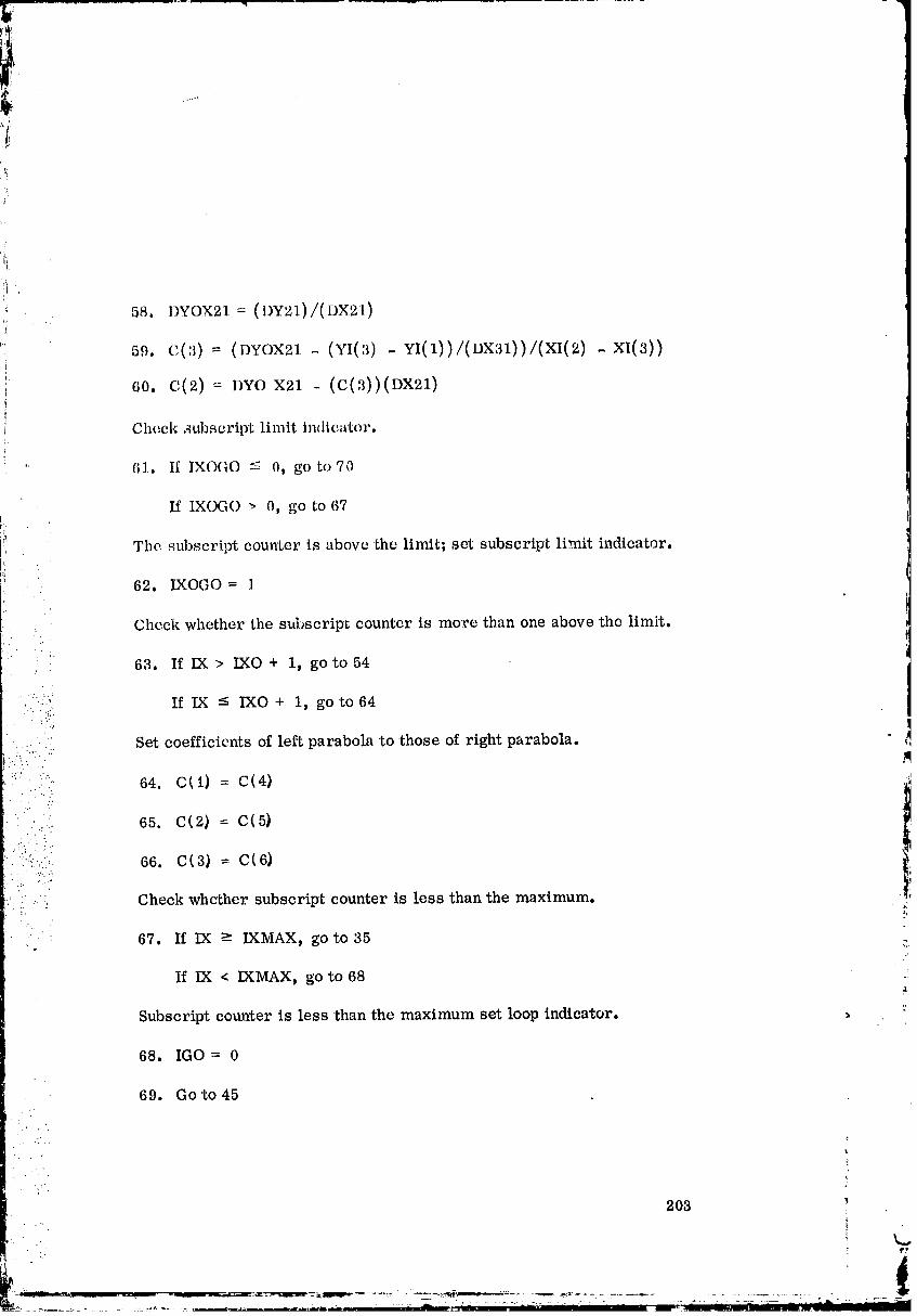
,1¢
_r
,i
i
ii
J
58. DYOX21 = (DY21)/(DX21)i
_;; 59. C(3)= (DYOX21- (YI(3) - YI(1))/(DX31))/(XI(2) -XI(3))
60. C(2) = DYe X21 - (C(3))(DX21)
Cheek subscript limit indicator.
" 61. If IXOGO _ O, go to 70
If IXOGO _ O, go to 67
rl,)t is above 'the limit; set subscript limit indicator.The subsc i., counter
62. IXOGO = 1
Check whether the subscript countcr is me:re tban one above the limit.
63. If IX > IXO + 1, go to 54
"::/ If IX -< IXO + i, go to 64-. ._:;
,: Set coefficients of left parabola to •those of right parabola.
• : :: 64. C_I) = C(4}• ....
: 65. C(2} = C(5}
: i: :il Check whether subscript counter is less 'than the maximum..-...
. 67. If IX _- IXMAX, go to 35 :.
If IX < IXMAX, go to 68:t
Subscript counter is less than the maximum set loop indicator.
68. IGO = 0
69. Go to 45
203
• _ f',
!
00000004-TSD13

Compute difference between x and x i_1.
, 70. DX1 = X - XI(1)
Compute dependent variable value from 'the left parabola.
71. YBI= ((C(3))(DX1) + C(2))(DX1) + C(1)
Compute derivative of dependent variable,
72. YPB1 = (C(3))(DX1)/(0.50) + C(2)
Check loop control indicator.
73. If IGO > 0, go to 89
If IGO - 0, go to 74
Compute dependent variable value from the right parabola.
74. YB2 = ((C(6))(DX2) + C(5))(DX2) + C(4)
, Compute derivative of dependent variable.
75e YI_B2 _ (C(6)) ( DX2) /( 0. 50) Jr C(5)
Check loop control indicator.
76. If IGO < 0, go to 92
If IGO -> 0t go to 77
Compute U (x), U2, and U3 for the cubic weighting function.
77. U1 = (DX2)/(DX32)
7s. u2 = (m)(vl) "
79. U3 ffi (U1)(U2)
Compute the cubic weighting function _.
80. _lffi (3.0)(U2) - (2.0)(U3)
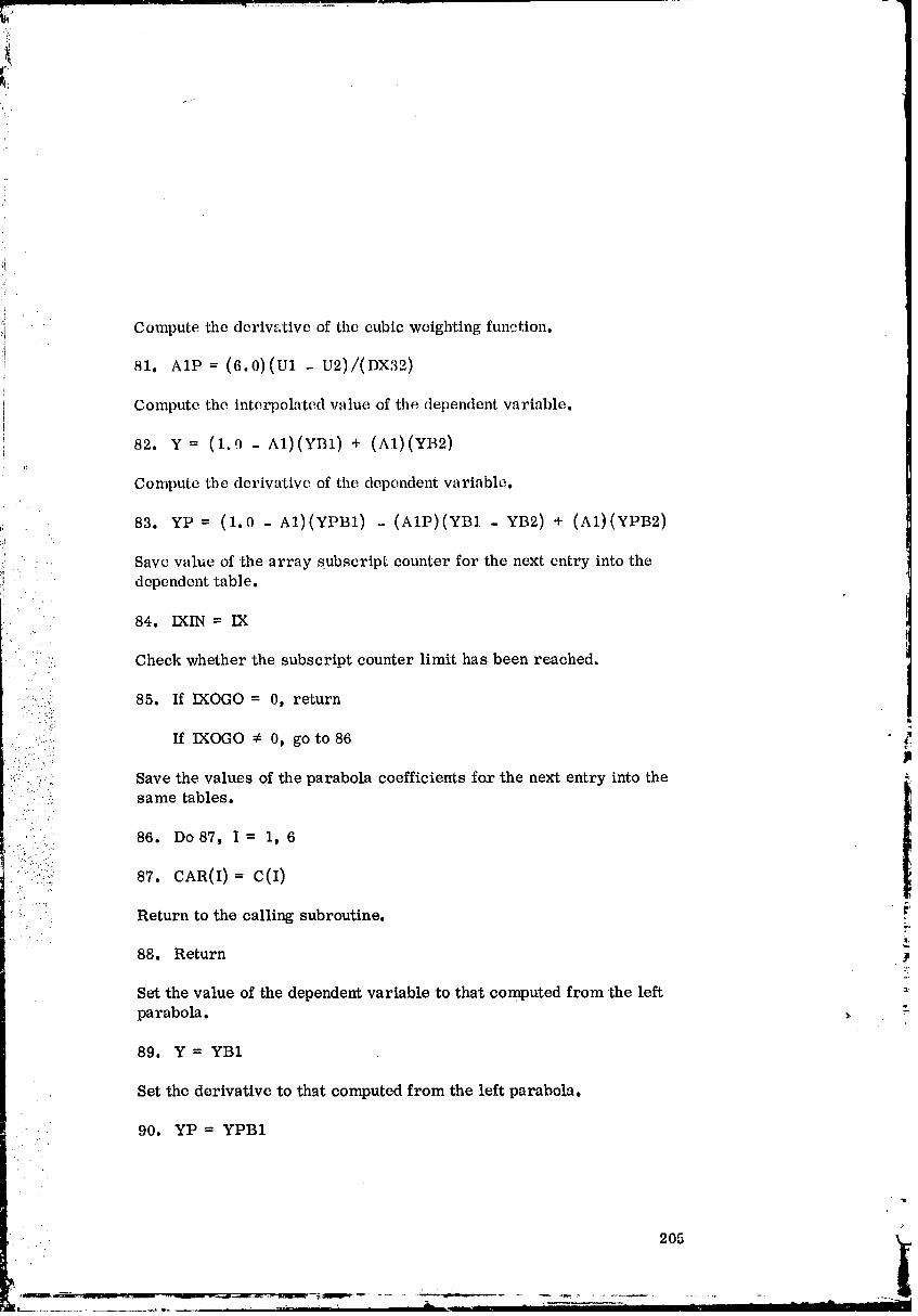
[i,..--
• Compute the derivative of the cubic weighting function.
- X'81. AlP -- (6.0)(u1 U2)/(D ._2)
Compute the interpolated value of the dependent variable.
82, V = (1.0 - A1.)(YB1) + (A1)(YB2)
Compute the derivative of the dependel_t variable,
'. 83. YP = (1.0 - A1)(YPB1) - (AIP)(YB1 - YB2) + (AI.)(YPB2)
;; . .' .: .; Save value of the array subscript counter for 'the next entry into thedependent tab]e.
.: .,./.84. IXIN = IX
- . .;:
• - 2:. Check whether the subscript counter limit has been reached.
.- .-u, •. ?'
8s. If oGo--0,return•" "::....... If IXOGO ¢ 0t go to 86: -'.'..:.
• 2" "'V " _.:.':
::: .. ....: Save the values of the parabola coefficients for the next entry into the: -: -.; same tables.: 2':":' 86. DO 87, I = 1, 6
:%.:')::
....,_:..:. 87. CAR(I): c(I)?: .....::
• Return to the calling subroutine.• :...
88. Return . iP
Set the value of the dependent variable to that computed from 'the lefto
parabola. _ -
89. Y = YB1
Set the derivative to that computed from the left parabola,
: . 90. YP = YPBI- ...

!i
• . Save array position indicator and parabola coefficients.
91. Go to 84
Set the value of 'file dependent variable 'to 'that computed from the rightparabola.
,_ 92, Y = YB2
Set the derivative to that computed from 'the right parabola.
93. YP = YPB2
..... Save array position indicator and parabola coefficients, t!
94. Go to 84i,
Table 16 gives 'the subroutine XNTERP nomenclature.
....::" TABLE 16. SUBROUTINE XNTERP NOMENCLATURE
=........ Symbol Description Units Reference
:.::: .ii::., A1 Cubic weighting function o_(x) 80, 82, 83
" :_ AlP Derivative of the cubic weighting 81, 83:.!': : :.. .: function o_' (x).: _ : C hzternal array of coefficients for DIM, 5t 41-43,::-.:!::.: right and left parabolas 45, 49, 50, 54,
.. 59, 60, 64-66t
: i:!.....! 71t 72_ 74_ 75_•_'" 87
• " ' CAR Input or output array of CALL, DIM_ 5,parabola coefficients for 87
.input tables
DX1 Difference between value of 70, 71 ,independent variable x and
the second table point less than
x (x - xi_l)DX2 Difference between value of ..... 23, 72, 74, 75t
• independent variable x and the 77
...... first table point less than or
equal to x (x - xi)
•.. 206 ! (i
1.... -r ...... v-'--Nilfill ......... "1
O0000004-TSF03
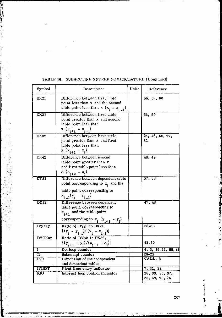
i ¸ •
TABLE 16. SUBROUTINE XNTERP NOMENCLATURE (Continued)
Symbol Description Units Reference
DX21 Difference between first { ble 55, 58 t 60point less than x and the second
table point less than x _(xi - x.l.1 )
'_ DX31 Differcncc between first 'table 56, 59point greater than x and second
table point less than
x (xi+ 1 - x.,_l)
. .. DX32 Difference between first table 24, 48, 50, 77,:. point greater than x and first 81
•table point less than
x (xi+ 1 - xi)
.:: DX42 Difference between second 46, 49
table point greater-than x
and first table point less than
.'..-_' x (xi+ 2 - xi)• , -- wq
:'.: DY21 Difference between dependent -table 57, 58 2,.....:.::.," point corresponding to x. and the im1
i:::_.i' table point corresponding ton _
n _ n_ _ _
xi l(Yi - Yi-1)I . , . m
'_ DY32 Difference between dependent 47, 48•/_:" ?:i"
-:.', .... table point corresponding to......
._. xi+ 1 and the 'table point
_.::". correspondingto xi (Yi+l m yi) _"_'•" DYOX21 Ratio of DY21 to DX21 58-60 _,
L(Yi - Yi-i1/(x. - xi_l)] .r1
DYOX32 Ratio of DY32 to DX32, _:
[(Yi+l -Yi)/(-Xi+l - xi)] 48-50 . :
I Do-loop counter 4, 5, 19-22, 86, 87
I1 Subscript counter 20-22IAR Dimension of the independent CALL, 2
and dependent tablesIFIRST First time entry indicator 7t 31_ 32 '
- IGO Internal loop control indicator 28, 33, 35, 37,53, 68, 73, 76
• i9.07
O0000004-TSF04

TABLE 1.6. SUBROUTINE XNTERP NOMENCLATURE (Continued)
Symbol Description Units Reference
IPOS Input array position indicator CALL, 3IX Array subscript counter 3, 9-13, 16-18,
20, 25, 27, 30,
q 40, 52, 63, 67,84
IXIN Firsttime entry indicatoror CALL, i, 84saved value of subscript
counterfrom previous entry
IXMAX Working maximum lengthof 2, 8, 14, 18,
: the input tables IAR - 1 30, 67IXO Internallimitfor thesubscript I, 6, 8, 25,
counter 40, 63
IXOGO Subscriptlimitindicator 26, 39, 51, 61,i 62, 85
U1 Ratio of DX2 to DX32 77-79, 81
[(x - x')/(xi+11 - xi)]
U2 U1 squared 78-81 ,_:".... U3 U1 cubed 79, 80
:":ii':. X Input value of the independent CALL, 11, 14,variable 16, 23, 70
.. XAR Input array of independent CALL t DIM,variables 11, 14, 16, 21
' :-i! XI Array of table points surrounding DIM, 21, 23,the input value of the independent 24, 46, 49, 55,
-..: var'able 56, 59, 70
., Y Output value of the dependent CALL, 82, 89, _:variable corresponding to the 92independent variable :-
YAR Input array Gf dependent CALL_ DIM,
variables 14, 22YB1 Value of dependent variable 71_ 82, 83, 89 :
on the left parabola
YB2 Value of dependent variable 74, 82, 83, 92on the right parabola
YI Array of dependent table points DIM t 22, 45,
corresponding to the XI values 47, 49, 54, 57, .'59
208
O0000004-TSF05
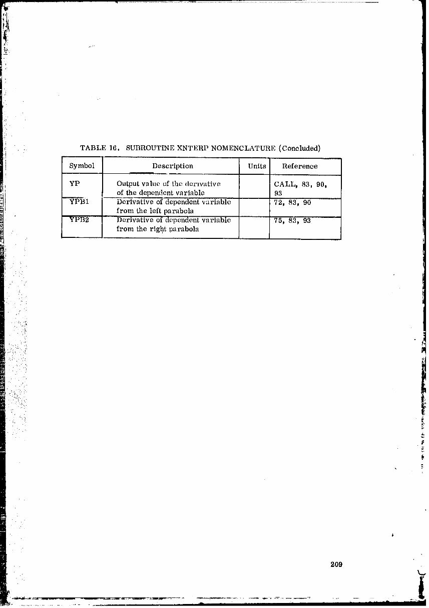
. : TABLE 16, SUBROUTINE XNTERP NOMENCLATURE (Concluded)
Symbol Description Units Referencer.
YP Output value of the dcrwative CALL, 83, 90tof the dependent variable 93
" YPB1 Derivative of dependent variable 72, 83, 90from the left parabola
YPB2 Derivative of dependent variabIe 75, 83_ 93from the righ.t parabola
• 2O9..
O0000004-TSF06
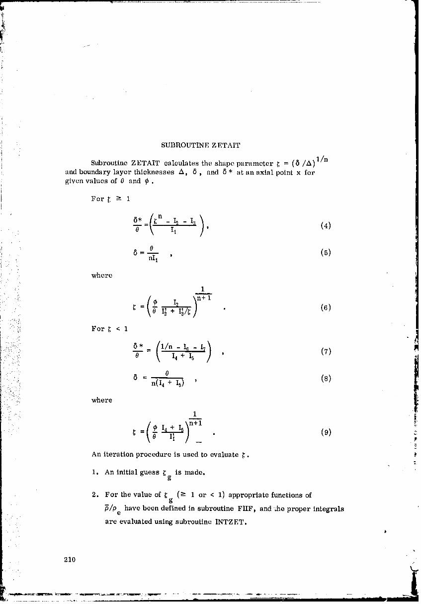
SUBROUTINE Z ETAIT
Subroutine ZETAIT calculates the shape parameter ._ = (8/A) 1/nand boundary layer thicknesses A, 8, and 8 * at an axial point x forgiven values of 0 and _b.
For _ _ 1
'_ --8" (_n - I_ - I'_ )'0 = 11 (4)
jr ,_ 8 =-- (5)ni 1 ,
: :. where
•_ 1
i2 n+ 1'_:::,. _ = I_+ I_/_ • (6)
':. For._ < 1
....... [ )• .... 8, 1/n - 16 - I? 15i:!i:::-(.: - (7)
:.:.;....::. O \ 14 + Is '. . ...::
1
,, . ',
..... _ = (s): .'.:: n(I 4 + 15) '
:::.;:: where
-_ = g i_ • (9) _-
An iteration procedure is used to evaluate ._.
1. An initial guess _ is made.g
2. For the value of _ (e 1 or < 1) appropriate functions ofg
• "fi/Pe have been defined in subroutine FIIF, and ;he proper integrals
. .: are evaluated using subroutine INTZET.
210
P
O0000004-TSF07
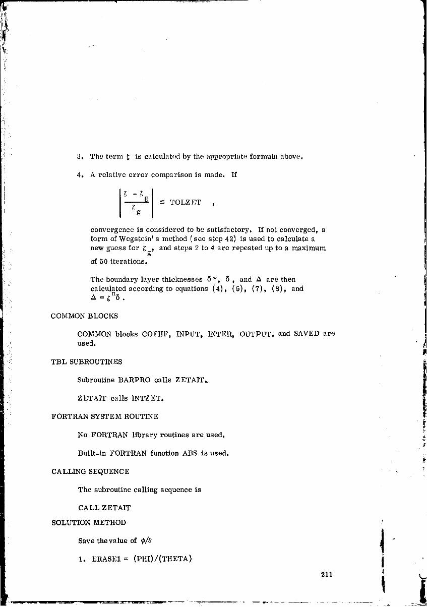
3. The term _ is calculated by the appropriate formula above.
4. A relative error comparison is made. If
- _g -< TOLZET ,g
convergence is considered to be satisfactory. If not converged, aform of Wegstcin' s method (see step 42) is used to calculate a
new guess for _g, and steps 2 to 4 are repeated up to a maximumof 50 iterations.
The boundary layer thicknesses 5", 5 , and A are thencalculated according to equations (4), (5), (7), (8), and
• A = _n6 .
COMMON BLOCKS
COMMON blocks COFIIF, INPUT, INTER, OUTPUT, and SAVED are !_ used.
::' TBL SUBROUTINES
Subroutine BARPRO calls ZETAIT._
.... ZETAIT calls INTZET.
FORTRAN SYSTEM ROUTINE
No FORTRAN library routines are used. __
Built-in FORTRAN function ABS is used. *:
CALLING SEQUENCE -
The subroutine calling sequence is
CALL Z ETAIT
SOLUTION METHODi
Save the value of _/0 _ "!
1. ERASE1 = (PHI)/(THETA) i
211 _ ml
i
O0000004-TSFO8
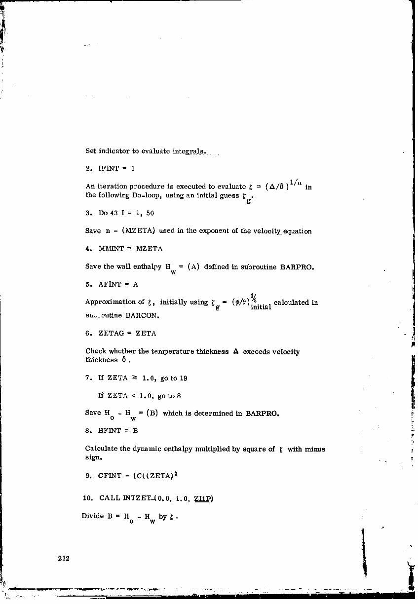
},
Set indicator to evaluate intcgral_s... .....
2. IFINT = 1
An iteration procedure is executed to evaluate _ = (A/5)1/, in
the following Do-loop, using an initial guess _g.
3. Do 43 I = 1, 50
Save n = (MZETA} used in the exponent of the velocity equation
4. MMINT = MZETA
Save the wall enthalpy H -- (A) defined in subroutine BARPRO.w
5. AFINT = A
Approximation of _ initially using _g = (_/e) 1/8 .calculated in
' initia,
su_._ outine BARCON.
6. ZETAG = ZETA
Check whether the temperature thickness A exceeds velocitythickness 8.
7. If ZETA _ 1.0, go to 19
If ZETA < 1.0, go to8
Save H - H = (B) which is determined in BARPRO.O W
8. BFINT = B
Calculatethe dynamic enthalpymultipliedby square of _ with minus
sign.
9. CFINT = (C((ZETA) 2
I0. CALL INTZET-(O. O, i. O, ZllP}
Divide B = H - H by _.O W
212
11
O0000004-TSF09
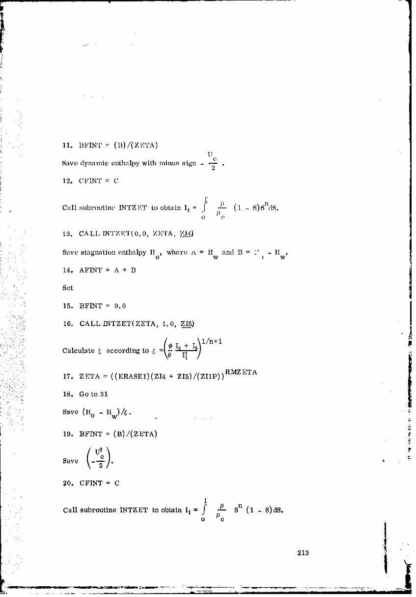
!!'i
J
!i /i
.' 11. BFINT -- (B)/(ZETA)U
e
Save dynamic enthalpy with minus sign - -_- .
12. CFINT = C
20. CFINT = C
1
Call subroutine INTZET to obtain I1 = f _ Sn (1 - S)dS.o Pe
1
• 213 ,
O0000004-TS F 10

22. BFINT " B
U2
e _,_, Compute - -7 .
23. CFINT = (C)(ZETA) 2
Set (1/_).
24. ERASE2 = (1.0)/(ZETA)
f _P Wn (1 - W)dW.Call subroutine INTZET to obtain I{ = j PO e
25. CALL INTZET( 0. 0. EBASE2, ZI2__._P).
: : Save (n - 1).
• 26. MMINT = MZETAM
• ." .
: :: Calculate (H - U2/2).W e.. _.,
:..%.
27. AFINT = A + C
• _. Set.-.:.
z.
28. CFINT = 0.0
1
_ _ w__,!_(_-W)dW. :Call subroutineINTZET to obtainI_ = Pe
29. CALL INTZET(ERASE2, 1.0, ZI3__P}
O0000004-TSF11
37. Z3 " Z4
38. Zl = Z2
". 215
O0000004-TS F13
39. Z4 = ZETA
40. Z2 = ZETAG
41. z5 = (z4 - z3)/(z2 - zl)r
Approximate a new _ using a form of Wegstein' s method.g
42. ZETA= (Z4 - (Z5)(Z2))/(i.0 - Z5)
• 43. Continue
: . " ..
• ' '.' Print out the error indication of shape parameter iteration failure.
44. WRITE X_ ZME_ THETA_ PHI. "-....
:: 45. WRITE Z1, Z2, ZETAt Z3, Z4
• ...: .... Proceed with calculation when convergence is obtained.
Set IFINT equal to two.
46. !FINT = 2
• Save n in the exponent of velocity profile.
. ?::: :::_: 47. MMINT_= MZETA
Save wall enthalpy H .w
48. AFINT = A ...
Save (H - H )/_.O W
49. BFINT = (B)/(ZETA)
Save ( -U 2/2).e
50. CFINT = C
216
00000004-TSG01
nCalculate _ .
51. ZETATM-- (ZETA) ZMzETAL
Check whether _ exceeds one.
52. If ZETA >- 1.0t go to60
If ZETA < 1.0, go to 53
Call subroutine INTZET to obtain 16 = _' 0 SndSin the case _ < 1.0. o Pe
{ii: 53. CALL INTZET( 0. 0, ZETA, ZI__6).
:_ Save stagnation enthalpy H .o
54. AFIN_r = A + Bi
:, Seti.'..'.;
:': 55. BFINT = 0.0
1
Call subroutine INTZET to obtain I? = _J P---- SndS.
:, _ Pe
56. CALL INTZET(ZETA, 1.0, ZI___7).J
Calculate (I 4 + I5).
57. ERASE2 = ZI4 + ZI5
1- _ Is - 17
Compute 8'/0 = n in the case of j; -- 1, i.e., 8 _" A.14 + I_
58. DELSOT = (OOMZET - Zig - ZI7)/(ERASE2)
0 tObtain the velocity thickness 5 = _i-_5 . ,t
217 1 _'
00000004-TSG02
:1
:_ 59. Go to 67
1
Call subroutine INTZET to obtain 12 = f SndS
in the case of _ > 1, i, e., _ < A. o Pe
60. CALL INTZET( 0. 0, 1.0, Z_I.I2}.J
Save (n - 1).
61. MM1NT = MZETAM T
• - '. Save (H w - U2e/2).
! ::i:' 62. AFINT = A + C::.
•." ?
"- :,:: Set
63. CFINT _ 0.0. ....:, ;
.. ,. _ sn-lds.• -:.::_.: Call subroutine INTZET to obtain Ia =
i'(i? :i!: 1 Pe::" 64. CALL INTZET(1. 0, ZETA, ZI_.33).
0b.: Obtain the velocity thickness 6 = -- .
: . :.:.:. nI 1• ..:-..:
"-... 65. DELTA = (THETA)/(ZMZETA)/(ZI1)
6* _n/n - I_ - 130
C,._mpute -_ = ii
66. DELSOT = ((ZETATM)/(ZMZETA) - ZI3 - ZI2)/(ZI1)
Obtain the temperature thickness Z_ = _n 8 .
6','. BDELTA= (ZETATM)(DELTA)
Obtain the displacement thickness _}*.
_ . 218
00000004-TSG03

.,-,
i:
I:/
68. DELSTI{ = (THETA)(DELSOT)
69. Return
Subroutine ZETAIT nomenclature is given in T:lbh; 17.
TABLE 17. SUBROUTINI,: ZETAIT NOMI';NCLAI'Ill{E
Symbol Description Units l{efcrcn(,.(;
A Wall enthalpy H defined [t2/sec 2 /SA\ I',D/, 5, 14, 27w
.... . .. in subroutine BARPRO 48, 54, 62• .... AFINT Saved value of A ft2/sec 2 /COFIIF/, 5, 14, 27,
' 48, 54, 62:.....%.
B Stagnation enthalpy ft2/sec 2 /SAVED/, 8, 11, 14,: minus wall enthalpy 19, 22, 49, 54
_ " ::' calculated in BARPRO• . ".:..'.. •
• _:: BDELTA Temperature thickness A ft /OUTPUT/, 67...... " BFINT Saved value of B or ft2/sec 2 /COFIIF/, 8, 11, 15,
• _.:::."_"_::": B/ZETA 19, 22_ 49_ 55:.. . C Dynamic enthalpywith ft2/sec 2 /SAVED/, 9, 12, 20,
.:ii, : ' :: minus sign (-U2e/2) 23, 27, 50, 62 )1
• .._: : : calculated in BARPRO
:: . CFINT Saved value of zero ft2/sec 2 /COFIIF/, 9, 12, 20,
or 23,28,50,G3...... . .'"
•_: .. DELSOT Displacement thickness _ /OUTPUT/, 58, 66,• ,., _ divided by momentum 68
:: ... • :i thickness 6"/0DELSTR Displacement thickness ft /OUTPUT/, 68
: 6"
DELTA Velocity thickness 5 ft /OUTPUT/, "65, 67DZETA Relative error _ 31, 32
ERASE1 Energy thickness divided -- 1, 17, 30by momentum thickness
ERASE2 Temporary storage _ 24, 25, 29, '57, 58variable
I Do-loop counter _ 3, 33
219k..,
00000004-TSG04
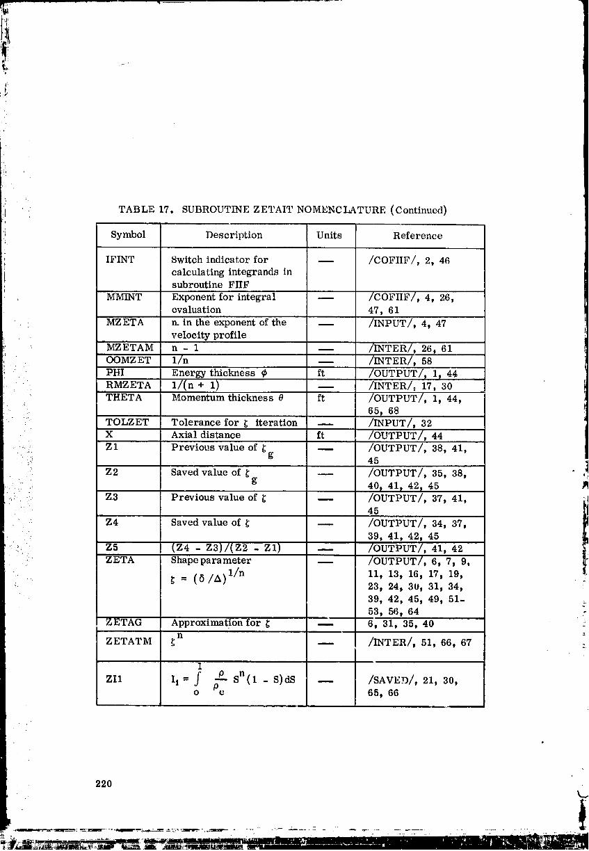
:i
TABLE 17. SUBROUTINE ZETAIT NOMENCLATURE (Continued)
Symbol Description Units Reference
IFINT Switch indicator for -- /COFIIF/, 2, 46calculating integrands insubroutine FIIF
. MMINT Exponent for integral -- /COFIIF/, 4, 26,evaluation 47, 61
MZETA n. in the exponent of the -- /INPUT/, 4, 47velocity profile
MZETAM n - 1 -- /INTER/, 26, 61
.... OOMZET 1/n -- /INTER/, 58PHI Energy thickness fb ft /OUTPUT/, 1, 44RMZETA 1/(n + 1) -- /INTER/, 17, 30
THETA Momentum thickness 0 ft /OUTPUT/, 1, 44,_- 65, 68
: TOLZET Tolerance for _ iteration -- /INPUT/, 32X Axial distance ft /OUTPUT/ 44
:_../: Zl Previous value of _ -- /OUTPUT/, 38, 41,g._. 45
Z2 Saved value of _ -- /OUTPUT/, 35, 38,g
'" .: 40, 41, 42, 45• . Z3 Previous value of _ -- /OUTPUT/, 37, 41,
" 45
Z4 Saved value of _ -- /OUTPUT/, 34, 37,
39, 41, 42, 45• *._:: Z5 (Z4 - Z3)/(Z2 - Zl -- /OUTPUT/ 41, 42
.. ZETA Shape parameter _ /OUTPUT/, 6, 7, 9,
/All/n, 11, 13, 16, 17, 19,(8:' 23, 24, 30, 31, 34,
39, 42, 45, 49, 51-53, 56, 64 .,
ZETAG Approximation for _ -- 6, 31, 35, 40 ::n
ZETATM _ -- /INTER/, 51, 66, 67 :
1F ---P sn(1 - S)dS -- /SAVED/, 21, 30,ZI1 It = 3 Po e 65, 66
220
O0000004-TSG05
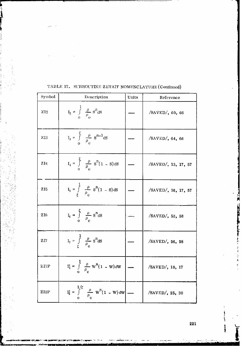
:1
00000004-TSG06
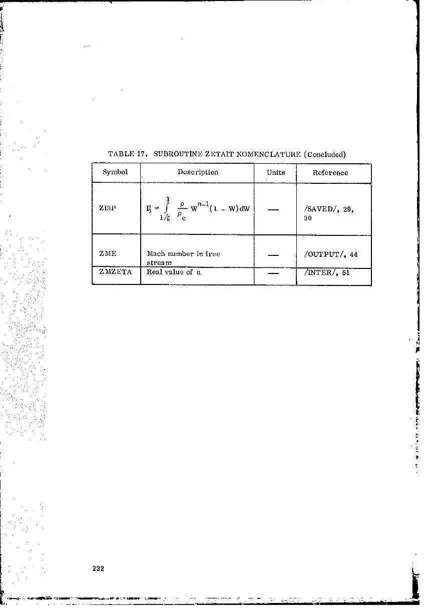
!•i
!,
TABLE 17. SUBROUTINE ZETAIT NOMENCLATURE (Concluded)
Symbol Description Units Reference
00000004-TSG07
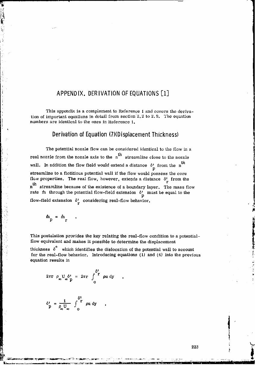
i.
i:!
.!
'i APPENDIX.DERIVATIONOFEQUATIONS[i]
This appendix is a complement to Reference 1 and covers the deriva-
tion of important equations in detail from section 2.2 to 2.9. The equationnumbers are identical to the ones in Reference 1.
Derivationof Equation(7)(DisplacementThickness)
The potential nozzle flow can be considered identical to the flow in ath
real nozzle from the nozzle axis to the n streamline close to the nozzle
wall. In addition the flow field would extend a distance 5' from the nP
streamline to a fictitious potential wall if the flow would possess the coreflow properties. The real flow, however, extends a distance 5' from the
th rn streamline because of the existence of a boundary layer. The mass flowrate fa through the potential flow-field extension 5' must be equal to the
:. p
flow-field extension 6' considering real-flow behavior.• " r
_ JI.... _ =_. . _
P r
1:, This postulation provides the key relating the real-flow condition to a potential-
flow equivalent and makes it possible to determine the displacement
thickness 6" which identifies the dislocation of the potential wall to accountfor the real-flow behavior. Introducing equations (1) and (4) into the previous _
equation results in _,
U 5' = 27rr f r pu dy ,2_'r Poo oo pO
51
= 1 f r pudy ,6'
P _ o
t
223
00000004-TSG08
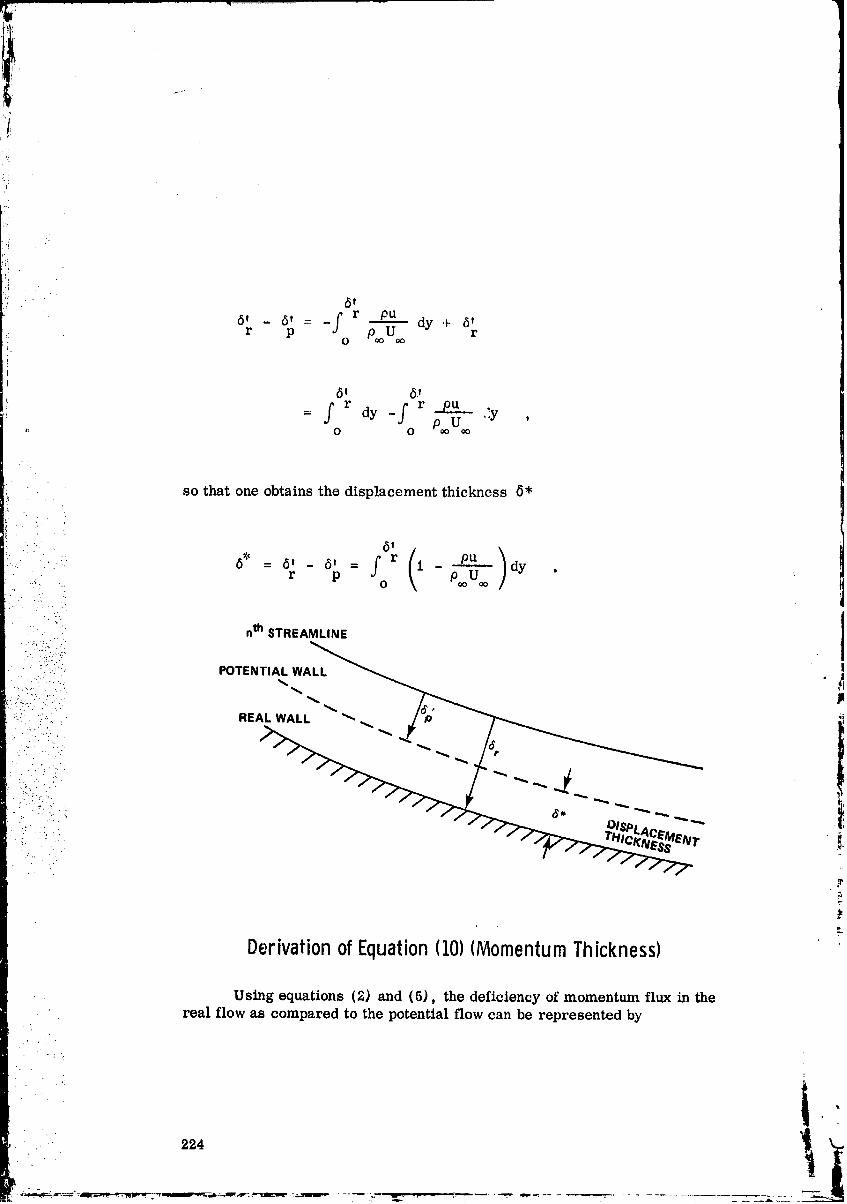
so that one obtains the displacement thickness 6'
Using equations (2) and (5), the deficiency of momentum flux in thereal flow as compared to the potential flow can be represented by
224
00000004-TSG09
i
'_' 5|
- _ = 2ur 2 5' - 2_r --f r PU2dyi_ l_Ip r p_ U P ¢ o
( °' ), o p=ol.J_
Introducing equation (7) yields
• . .'. ." ..
... 5 t
._....,._. 0,__0,__r(_-0---_/' ,.".";' p r : p_LTo dy ,'_ O
L. • .
"";.... [ /'( / /' ].....•-"-.'."'. i¢I - i¢/I = 2_r p.oU_ 5r _ r I - ..pu_ dy- r p...._•...i!:i.?:•,:.: p r o o ," ,. i ./'""
:Eli!:•:i..:'".D 1
.... " " = 2_r pooU2 r pu u dy ,"" " "'" ': _0 --• .' .i .: o P'oU'o_" .". .
• /:._,!..- -.
• :. " '_ ;"!' where the integral represents the momentum thickness O.
_" : DerivationofEquation113)(EnergyThickness)
Applying equations (3) and (6) yields the deficiency of enthalpy flax ofthe real flow as compared to the potential flow.
. . . _ ".
225
4i
O0000004-TSG10
61.i I
• _ - E = 27rr p_oUo (ti ° - H ) 6' - 2?rr f r pu(h - Hw ) dyO
Using equation (7) results in
.. 61
... p r o P_oU '
E - E = 2_rr p_oU (H - H ) 6' - f r I - dyp r ¢_ o w r. O Poo oo ]
.$
i ° i_ fr ou o w•" o pU-'-_ H - H dy
,., O W
i :\ !
" 6' ( h - It )= 27rr o oUoo (Ho - Hw)for p¢cucPU 1 Ho° - HWw dy . _."_
The integral represents the energy thickness ¢. , :
Definition of BoundaryLayerThicknesses
Displacement Thickness
6 I
226
00000004-TSG 11

Energy Thiclmess
6,
o p¢_U¢_ _- dy •
:. Derivationof Equation1161(Skin Friction Coefficient)..'.
• ' i_ The friction coefficient is defined by the force in direction along the• F
........_-_ wall per unit area _- = _r made dimensionless bythe dynamic pressure' -::'.. ':. W
•. :: ' ..... :..': _
• .=i".•." . , _ 21":," """ _. W
C. :. ::.!..-_: f 2. .-. PooU_
'. . "}/..
. ':":::'..i'_. ::.... ;,•.._
:, ' :,:_: Equation(171(StantonNumber) _.
This dimensionless parameter can be interpreted as the ratio of theheat flow density emerging from a wall for each degree of temperaturedifference between the wall and the fluid and the heat flow density convected
by the flowing medium for each degree of temperature difference•
NuSt -
RePr '
227
O0000004-TSG13
ii
il,
where
h_NU = -L
U_Re -- m
V
i h = specific heat transfer coefficient
g (contains all influences caused by properties and flow conditions),
= heat conduction coefficient (is a material constant),
i!= characteristic length _
t_
Therefore, the Stantcn number can be expressed by
, _ h' • st =-K- x_.__.
_,U Cpp_o '
--co- , • .
C = specific heat at constant preosure,P
P.o = density.
' 228 _
00000005
: i
" The total heat flow between a surface and a fluid is:p:i
b
' Q = hA(T F - T ) ,g w
Q. _ qw :-- h (TF - T ) ,g w .......
r
' qwh -
g T F - Tw '
. " ... Substituting this expression in the Stanton number yields
,., W
• St =
::i CppcoU¢o (T F - T w) '•. _'... .:::;V:"
• . ." ..
- .... ... or since ]_
" ._ ," " •i" " " .• .. ,, ,
T for C = constant,.:". -_ h = Cp P
: .'; ,..?. L
".': _ .:':" St =....•.: p U_o(Haw - Hw ) "., .. _.
Since T F is the temperature which a specific location on the surface assumes ?when the convective heat transfer is zero, it can be considered as the recoverytemperature. The corresponding enthalpy expression is the adiabatic wall :
enthalpy.
]t
229 _"
00000005-TSA03
'i
•- Equation(18)(AdiabaticWall,Enthalpy)
When a gas flows past an insulated or adiabatic surface, the tempera-ture at the surface will rise above the temperature of the free-stream gas
but will not quite reach the total teiaperature. The temperature at an adia-baLic surt'ace T is called the adiabatic wall temperature.
aw
'" In practice it has been found convenient to relate T and. T byaW ¢o
the recovery factcr R T , which is a measure of the fraction of the free-
stream, dynamic-temperature rise recovered at the wall. The term R Tis defined as
aw _o aw _ 2 J w
R T == _ =. 1 ."" T -- TT2•.. o oo (,y _ 1) M2
i. . oo OC, oo
2c JgP
........_
.,....-":. The derivation of this equation is shown below, lm
t••:::_•,••,-
. . T - T (Taw - T ) 2c gJ• . aw ¢o p
U2 U2 a 2. : . _ _ _
.....:::.' 2 c g J a 2p
• U i,
• . where speed of sound is a = 47gRT ' Machnumber M = --_ . ,-• _ a a _"
The refore,
T - T _(Taw - T ) 2c g Jaw oo _ p ,,
U_ M 2a 7 g R T,o
ao
2c gJP
k.
230
00000005-TSA04
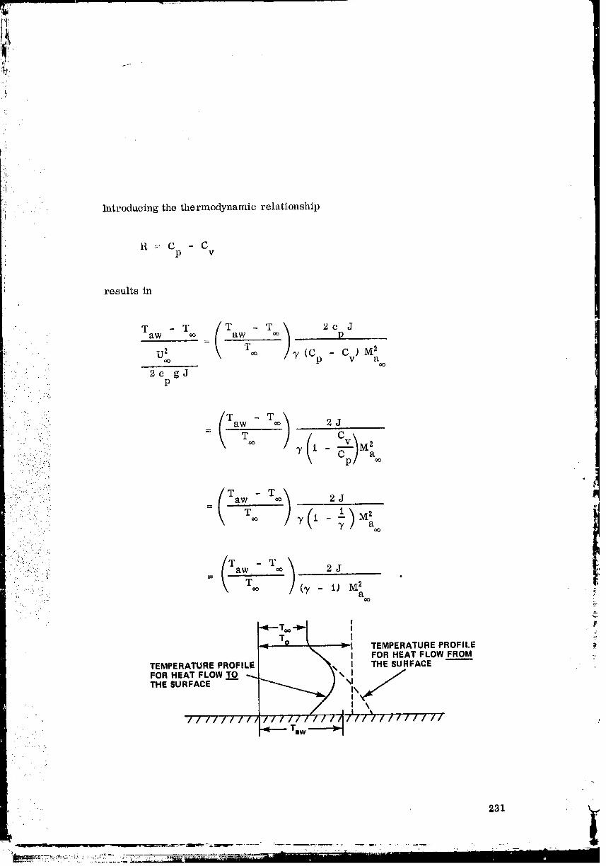
Introducing the thermodynamic relationship
,i
' R= C - Cp v
results in
p
_, For turbulent boundary layers the recovery factor R T can be approximated:_ " by the relation
3
R T _ _P"_r •
': The ratio of tile adiabatic wall enthalpy and the stagnati(m enthalpy is del'incdas
: U2
• H h + RT" _-• -' aw
• H U2 '• i". ...•i O• _.:: h+ _
2
where R T -- recovery factor [the fraction of dynamic enthalpy (or tempera-
ture) which, is recovered],
U2
= Cp (To - T_o) = dynamicenthalpy,
h =- free-stream static enthalpy°
• Rearranging the previous equation yields
..-i:i ::iI: u'H 1 + RT_aw 2 h
Ho U2
2h
and introda, ing the recovery factor R T = Pr 1/a for the turbulent boundary_ layer results in
. . . •
.. } 1
• .. 252
i- " .._. _.-. _ _ _ _-._- = • ,, _A
00000005-TSA06
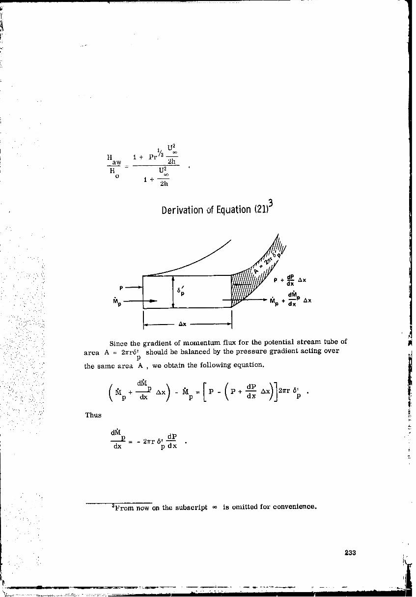
U21/H 1 + Pr/3
(.lo
aw 2hH - U2 '
O oo1+_
2h
,: Derivationof Equation(21)3
./'."'+W: . . .'i;
.....:. _ ._.ng/i,Y'./lY dP
' ': " "i:! P _ d_p• .._ ,.1] ,: .
! !.,..*-...,_,:......
!<" ' -' ... ." jlj]
;":_i)):7;":7::i.:(:;;::i .;i Since the gradient of momentum flux for the potential stream tube of II::.:..--:......- ' • area A = 21rr6' should be balanced by the pressure gradient acting over ,1
, . ., . -. . p
. i::.::.. ._:i.:.:i. the same area A we obtain the following equation.
1
• -... -.-:. 2" .*,.. : : .;.... 1:..
.: '::,.-- " ...:... + Ax - = P - P+-_x A 21rr .
L :: ._.:_ .: ..i:_ <)_. _i _' " '-- ...." Thus _:,
"- . 1; :.: : 3.
•: d_ -"&
= - 2_rr 6' d__.Pdx p dx "
'2..
00000005-TSA07

Derivationof Equation(23)
234
00000005-TSA08
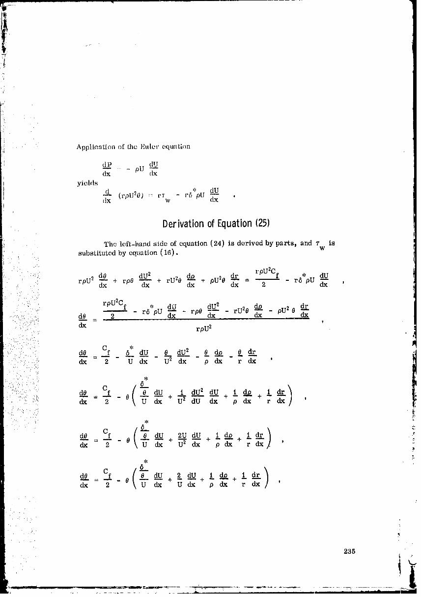
yr
L'
i.
ii
Application of the Euter equatbm
::i dP dU
dx pU dx
yields
d * dUdx (rplI20) :: rTw - r5 pU dx_ '
i
DerivationofEquation1251
The left-hand side of equation (24) is derived by parts_ and r is
substituted by equation (16). w
• : rpU2Cfdr * dU-:,. dO dU 2 _ + oU20 - r6 pU dx_ < rpU2 _xx + r00 -_x + rU_0 dx dx 2 'fl.
.- . >
." .. "-, _...
• . rpU2Cf _ _ dU 2 do dr: " : ",' dU rpO -_ - rU2O - pU2 0• " " ' d0 2 r6 pU dx dx dx
" .:'"".-..::'":i:_ dx rpU 2
:'..7 ' ' " d0 6 dU 0 dU 2 8 do _ 0_. dr....- ' dx - 2 U dx U2 dx p dx r dx '
.f
:":%. dO Cf ( dU 1 dU 2 dU i do I dr: : .'./.-, 4.. - 8 + i_2 + -- + --.... .::. i'.',, dx 2 _ _" dU dx p dx r dx '
( 'Cf dU 2U dU i d_ i dr ._
dO O + U2 + - + -_ _dx - 2 _ dx dx p dx r dx '
dx = "_ - 0 _" dx U dx p _ r dx '
235
.A
4
00000005-TSA09
(0, )•i! Cfi dO "_" dU 1 dU 1 dU 1 dp 1 dr:r _ =7" - 0 \b--/_- +U _ + Fdx+___+ _p dx r_" '
= 2 - 0 dU I dU+ 1 do + 1 dr_l-_+ _'d"_ " p dx r dx 'q:
Consider only the two terms
ldU 1 dp
Udx pdx "
• According to the mathematical definition
one can write
1 dU 1 dp dinU dU dlnp do
U d"-x+ .... ,]p dx dU dx + --do --dx-:.:..... _,
•" d In U d in O•:... _
.!i dx "+ dx
d_: : =-- (lnU + lnp):..'_ dx
! d_. =- [In (Up,)] '-.. dx _.
= d [In (Up) ] dU_.._p _.=
dUO dx2
1 dpU
pU dx '
#
236
00000005-TSA10

7
!i
Substituting this into the previous equation results in
_. dO C[. -_ dU 1 clot/ 1 dr! (l-'x_ Z - 0 + .-- U clx + pH dx _: dx
Derivationof Equations(26)and (27)i:
(leo me try
x dr
dz
)
c,..[ ,dr):" dz 2 1 + \_zz - 0 U dz + pU dz + r dz . (26)
:: This equation is applicable for axisymmetrie flow.
237
O0000005-TSA11
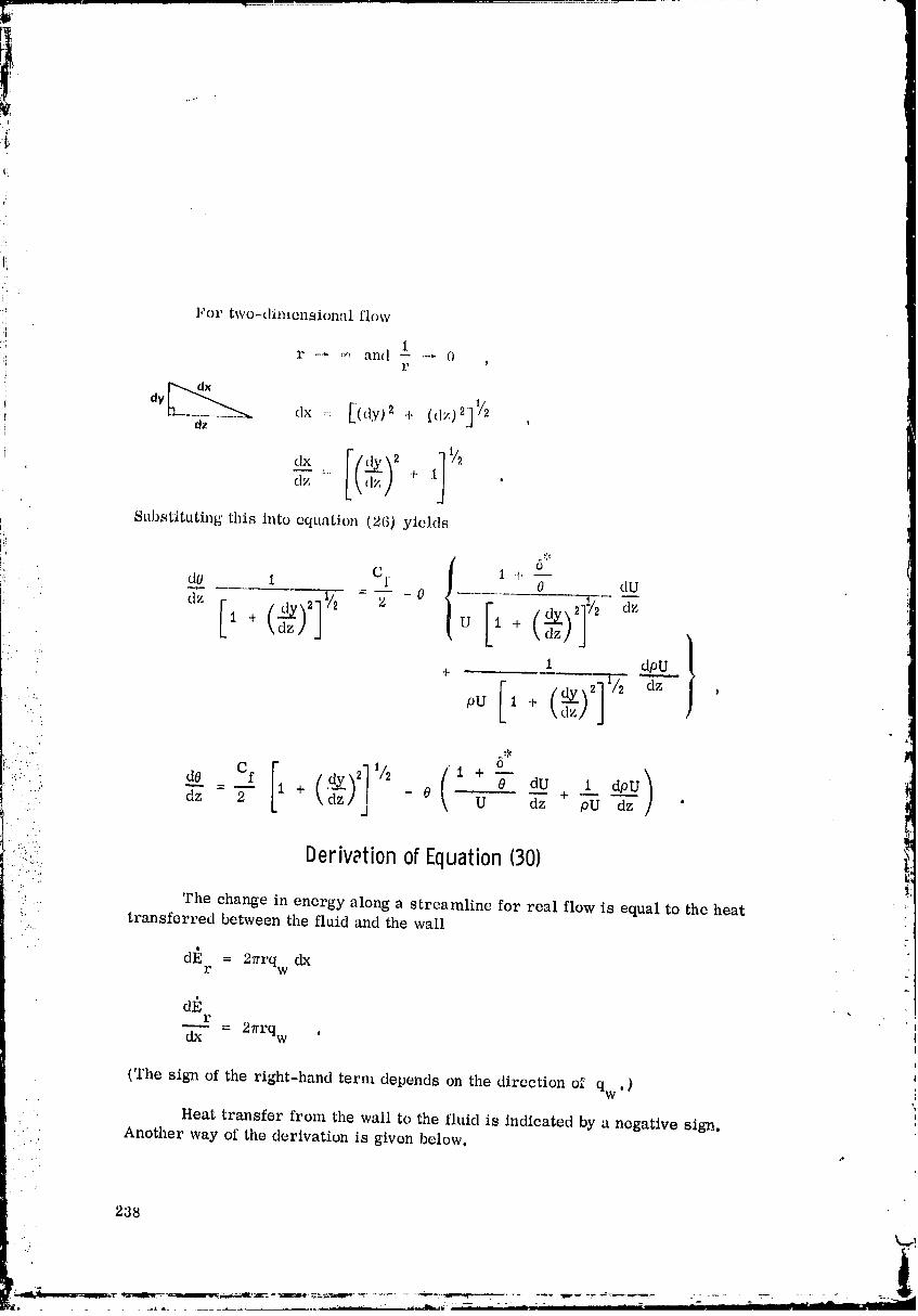
.... ,i,
tL
tl
ii
:, Derivationof Equation(30)• ..,.%.
i i,: The change in energy along a streamline for real flow is equal to the heat_. transferred between the fluid and the wall
dE = 27rrqw dxr
d_r
= 2_rrqw .
(The sign of the right-hand term depends on the direction el qw' )
Heat transfer from the wall to the fluid is indicated by a negative sign.
Another way of the derivation is given below.
238
......... 00000005-TSA13
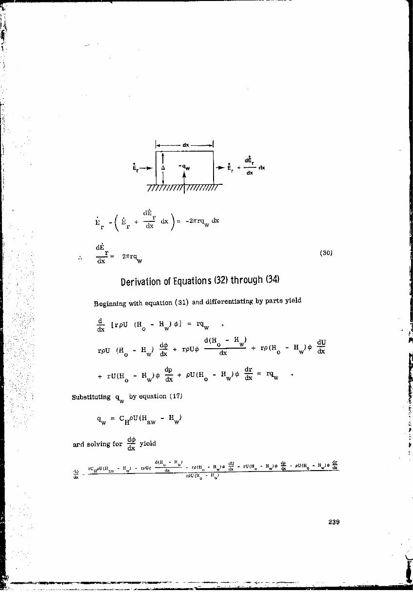
@,
_ _(_: + r ) _27rrqw•' r r -_x dx = dx
r... -- = 2_rrq (30)
.... dx w
. . .i".
..:- Derivation of Equations132)through 134)
: Beginning with equation (31) and differentiating by parts yield
,'--i';i!:":'"!- d
:i:ii(:: _ [rpU (H ° - H w) qS] = rq w ,
:.-:.::_..i:""..;....: d(H ° - H )
,:::;.:. :.. rpU _Ho' - Hw) d_dx+ rpU¢ dx w +-rp(tto - Hw)9 _dU lm
. . _ dr
:Z.:: :i: + rU(Ho - Hw)¢ _ + pU(Ho - Hw)_ _ = rqw "•. ":2':.. .
• :. • .:,- Substituting qw by equation (17)"" ._i:
" " qw = CHPU(Haw " Hw) !:£
ar.d solving for d_ yielddx
"2
d(Ho " HW) du dp - pU(H ° HW)¢ dr,1,2 _ rCHPU(Ilaw - Hw) - rpU¢ dx = rp(Ho " Hw)_ _'_ - rU(Ho " Hw)¢ (Ix "
dJt rpU(H ° - Hwl
• 239
O0000005-TSC01

d-'_ = CH - + - _ -H - H dxdz _ Ho o w
)... I d#U I dr
+ -- -- + - -- . (33)pU dz r dz
240
,_._. :.___:,_.:.:_,,L;y._T- _'_ ..... ;_ ' _ ....... I I I_ _ _ _ "'"
00000005-TSC02

For two-dimensional planar flow r --- _ ,V,I
r
dx _ (dy 2 + dx2) 1/2
d-_ = \_zz + 1
dz "
_J . . .
...: This equation substituted into equation (32) yields
d@ CH aw w 1 +•... dz = H H _zz - ¢ -H - H dzO W O W
..... .,
.... 1 dpU }•...., . . + . (34). ..... • ..:::' pU dz /, .... '.. .
' :: ::: Derivationof Equations(36)through 09)' ..', "" .'.i
l
; :., : The skin friction coefficient in a nozzle is assumed to be the same as
', ::_. for a flat plate at the same free-stream conditions p, U, p, T, M, the same...._ wall temperature T and the same momentum thickness 0. Unfortunately,
i:: :.... w '
...._ .: even this drastic assumption does not permit a completely reliable evaluation-J
:: of Cf since only the adiabatic skin friction coefficient Cfa , obtained when
T = T , is known accurately. The relationship between Cf and Cfa forw wa
severely cooled turbulent boundary layers, when gas properties vary greatlybetween the free stream and the wall, is uncertain. .:
The most accurate method for computing the adiabatic skin friction
coefficient Cfa is judged to be that of Coles [ 11]. He employs a transformation
method which gWes Cfa as a function of Much number M and the Reynolds
• number R based upon the momentum thickness as defined by
.. .:" .! .,
m
00000005-TSC03
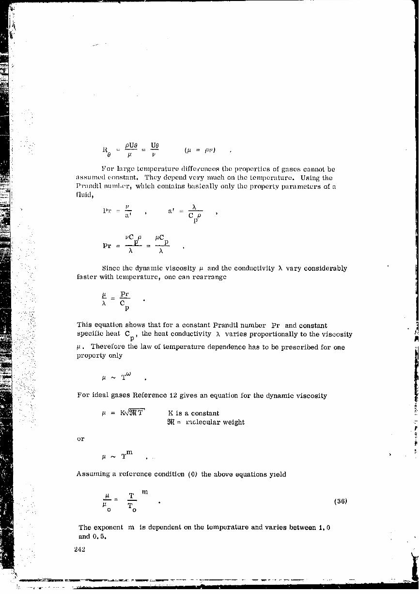
'.i ' :" R _ pUO _ UO (p = ps,)
_. For large temperature diffecences the properties of gases cannot be
assumed (.onstant. They depend very much on the temperature. Using tileI)randtl numl_cr, which contains basically only the property p,'trameters of afluid,
,_ 1_1?= _ a i _a I ' C p '
P
. _,Cpp pC• Pr - - .
'. " X X•..(. ::
! ;": '. Since the dynamic viscosity # and the conductivity k vary considerably' _ ;_'.; faster with temperature, one can rearrange
," . • ..-,;"
..: ,. p _ PrX C '
P
" :;!:(ii This equation shows that for a constant Prandtl number Pr and constant• ....'. t
:i:;7:_.i::i(.! specific heat Cn the heat conductivity _. varies proportionally to the viscosity '
• ..:,:.:..;:...:..:::,: p. Therefore the law of temperature dependence has to be prescribed for one :::1• : .., property only
1
. . . ..%
;:...',i:;. --W::.:_):;.":7.7":: p ~ T .
.,: .....-,: For ideal gases Reference 12 gives an equation for the dynamic viscosity
:. i:'.."if.:: " = K_,/-_--_ K is a constant i'
".:._ _ =mclecular weight :
or
p ~ Tm
Assuming a reference condition (0) the above equations yield
i
m
... U _ T (36), ,; . ',' _: T "
O O
The exponent m is dependent on the temperature and varies between 1, 0and 0, 5.
242
00000005-TSC04
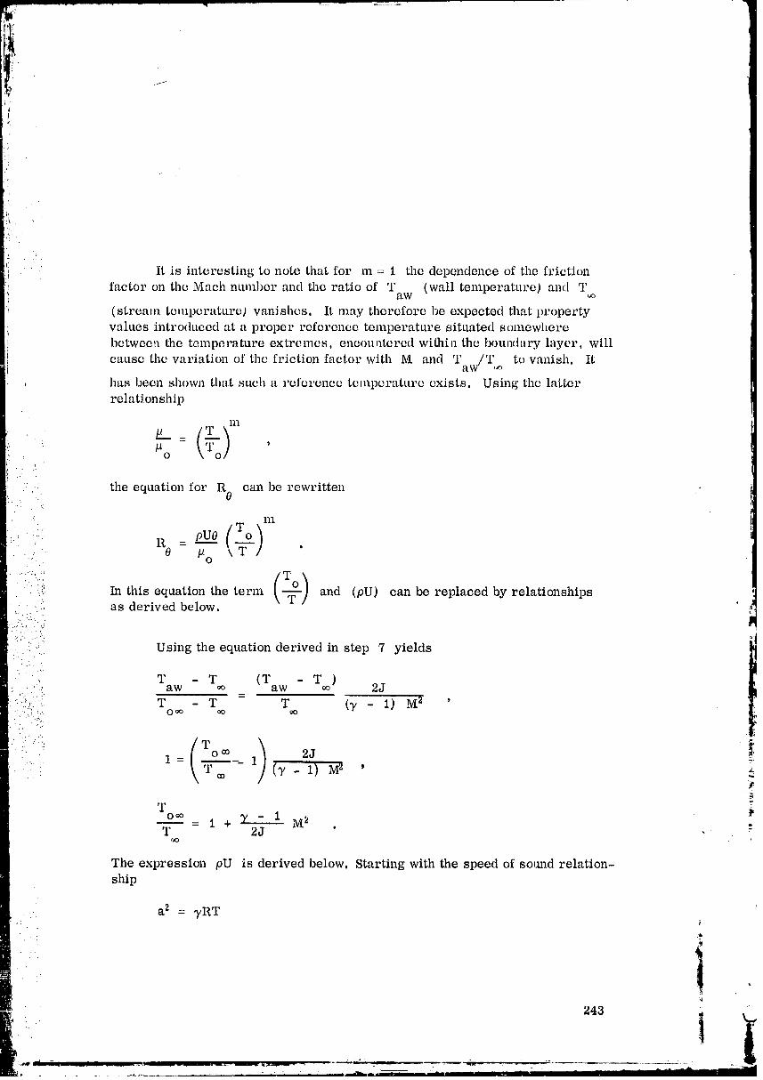
:}
'!
itisinterestingto note thatfor m = I thedependence ofthe frictionfactor on the Much ntuuber and the ratio of T (wall temperature) and T
aw
(stream temperature) vanishes. It may therefore be expected that propertyvalues introduced at a proper reference temperature situated somewhere
between file temperature extremes, encountered wifllill the boundary layer, will
cause the variation of the friction factor with M and 'raw/Tf, _ to vanish. It
has been shown that such a reference temperature exists. Using the latter
relationship
111
, .o" ," .. the equation for R 0 era1 be rewritten
•: nl
R0 - #o
¢: In this equation the term and (pU) can be replaced by relationships
,ii.i. :':_ as derived below.
i.:(i:..))I Using the equation derived in step 7 yields
•, T - T (Taw - T )i :..'::.! aw _o _ 2J.:.b:::.. T - T = T (_ - 1) M2 '
.-,C.... o_ _ _o
' )gT
T°_° Z- 1 M_ -__T - I + 2J "r_o
The expression pU is derived below. Starting with the speed of so,rod relation-ship
a 2 = _RT "
•"4
00000005-TSC05
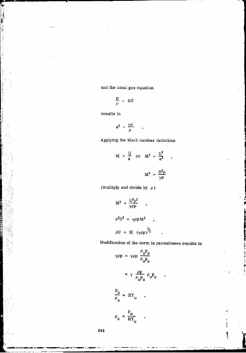
:ii,, and the ideal gas equation
results in
a 2 = __. s
P
Applying the Mach ntauber definition
PO_= RT ,Po o
PO _"PO = "_ "-
0i
244
00000005-TSC06

i:
ypp = 3/ PP PoPoPoPo RT o
= 3_. _p°2 -P-P--
T RTo PoPoi:
Application of the adiabatic relation between density and pressure
_R = c (_ - l) ,P
:• |
!245
I_A ..... p
00000005-TSC07
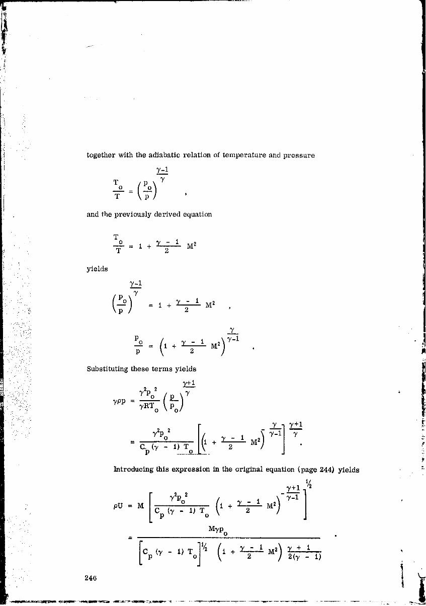
!i' i . .
J
together with the adiabatic relation of temperature and pressure
"/-__!1T 7
i T tttI
,: and tlle previously derived equation
To _ 1 +T - 1 M2
!_ T 2
i; . yields
"/-13'
•:... = 1 + :Y_- 1 M 2"" 2
... :':...:_. _]
i :._'_,_" ...... P 2 "
..:._:-."::".::i::'.iI Substituting these terms yields_+1 i: _.,::.;.... 7PP = 7RTo• ::: " .?.
•"-....
Introducing this expression in the original equation (page 244) yields "-
_"'+.-.l1 I/_
"%'-1_T ( )_-ipU = M Cp _"7 o 1 + T 2- 1 M2
MTPo
" Cp (7- i)T O 2 2(7 - I)
00000005-TSC08

, I,_P
Colos [ 11] shows that the available data on tim variation of Cfa
(adiabatic skin friction coeffieicmt) with R 0 and M can be correlated within afew percent by a singk', curvv a
Cf s (q7)[tawPaw Cht .
Multiplying by R0 yichls
• .. ' • CfR 0 - PP C faR 0 , (38)•.7 PawPaw
. . .'
where Paw m_d gaw are the density and viscosity evaluated at T and /_" aw s
..".- .:.... ij.-c. -,' is the viscosity at a mean sublayer temperature T given by.. ;. S
(.. s - 1 + 17.2 0 1 - 305 o T....... T T - T T 2 . (39) M
aw aw aw aw _5"2" "-',.
It is evident that Cf and R0 are merely values of Cfa and R 0 for low-speed.... .
- .: • flow. Coles' relation between Cf and CfR 0 is shown in the Figure A-I.
0.007 _'
i :I 0.006
0.005 ,_:
0.004 ;r
i0.003 r..
0.002 _ t
0.001 .
100 10t 10: 103 104
CfR0
Figure A-1. Coles' relation between Cf and Ct_t0 .
00000005-TSC09
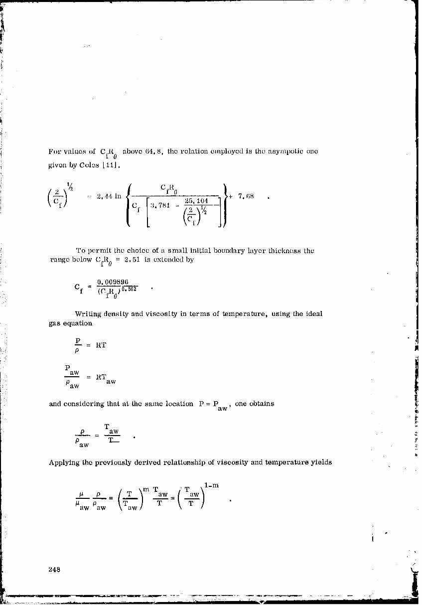
,i
i.
For values of CfR 0 above 64.8, the relation employed is tile asympotic one
given by Coles [ 1lJ.
.... 2. 441n 'Cf :1.781 - 5. 104 _." + 7.(18 .
To permit the choice of a small initi'd boundary layer thickness the
range below CfR 0 = 2.51 is extended by
0.009896
Cf = (C.t_O)o.5_2 ...'. ..
Writing density and viscosity in terms of temperature, using the idealgas equation
p" --= RT
_...: p tl
!: P
[ii. aw - RTPaw aw
and considering that at the same location P = P , one obtainsaw
Tp = aw -_
p Z_ " taw .::.
Applying the previously derived relationship of viscosity and temperature yields
m T )l-m/_aw Paw \ awl T _ '
/.
248
O0000005-TSCIO
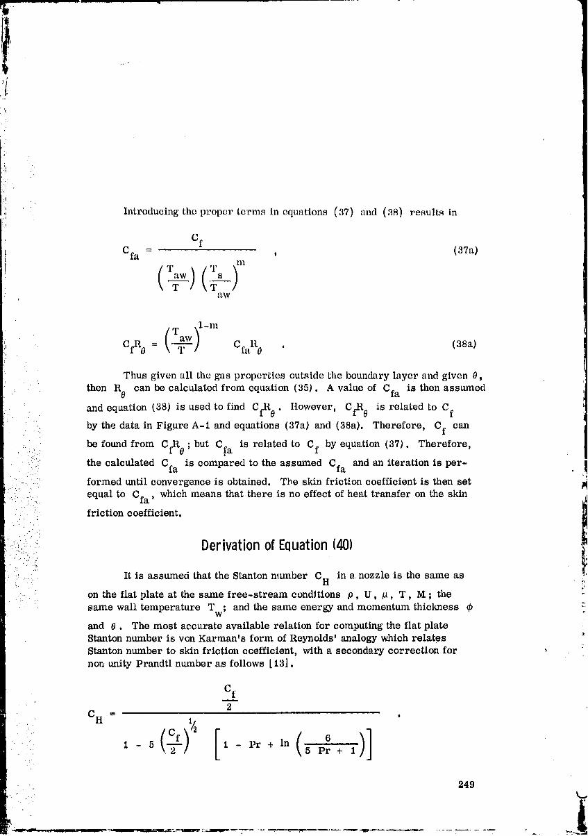
i
'!I
(
,i Introducing the proper terms in equations (37) and (38) results in
Cf
Cfa = , (37a)nl
aw
T ,1-m
C£R0 = _-- C faR 0 . (38a)
Thus given all the gas properties outside the boundary layer and given 0,
then R 0 can be calculated from equation (35). A value of Cfa is then assumed
and equation (38) is used to find CfR 0 . Itowever, Cil_ 0 is related to Cf
by the data in Figure A-1 and equations (37a) and (38a). Therefore, Cf can
......-. be found from CfR 0 ; but C.fa is related to Cf by equation (37). Therefore,
.... the calculated Cfa is compared to the assumed Cfa and an iteration is per- ,I• .,...
....:: " formed until convergence is obtained. The skin friction coefficient is then set?..
':.:.... .. equal to Cfa, which means that there is no effect of heat transfer on the skin• :::: friction coefficient.
. ." . •
;:_., • Derivationof Equation(401.'."4.....
. .. •,.._'
'i:....." It is assumed that the Stanton mLmber CH in a nozzle is the same as !:.... on the flat plate at the same free-stream conditions p, U, #, T, M ; the
same wall temperature Tw; and the same energy and momentum thickness _ "
and 6. The most accurate available relation for computing the flat plate8tanton number is yon Karmants form of Reynolds' analogy which relatesStanton number to skin friction ccefficient, with a secondary correction for :
non unity Prandtl number as follows [I3].
Cfm
CH = .
•. ( )]-:-.. °1 - 5 , 1 - Pr + In 5 Pr + 1'
249k.,
_|
O0000005-TSC 11
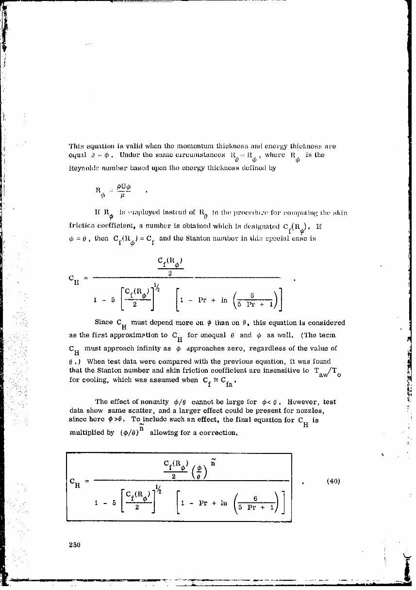
,!
i
This equationis validwhen the momentmn thicMms_ and cnorgy thiclmessare
cqual 0 = 4) • Under tile same c_rcumstances R 0 =: Rq), where Ilqb is the
Reynold_ number based upon the energy thickness defined by
]i -=ouq
If 11_ is ,.unploycd instead of R0 in lhc. l)roec:dure for (,Omlml.ing I.he skin
friction coefficient, a number is obtained which is designated Cf(R_). If
Cf Cf L,.:-;_,: q_= 0, then (Rgb) = and tile Stanton llUlllb_r in '" _:pocial cane isl
, cf(R)2
C H =
1 - 5 1 - Pr + in 5 Pr + 1
:: Since CH must depend more on _b than on 0, this equation is considered
as the first approximation to Cti for unequal 0 and _ as well. (The term
C H must approach infinity as _ approaches zero, regardless of the value of
0 .) When test data were compared with the previous equation, it was found
:.. that the Stanton number and skin friction coefficient are insensitive to Taw/To
.... The effect of nonunity 4_/0 cannot be large for _b< 0. However, test _!I
_' . data show same scatter, and. a larger effect could be present for nozzles, .
.... since here _ >0. To,,,include such an effect, the final equation for CH. is ., I
multiplied by (¢/0)n allowing for a correction, i
n
(0c n = . (40)
6
1 - 5 2 1 - Pr + in 5 Pr + 1.. • ._ ,_
250
00000005-TSC13
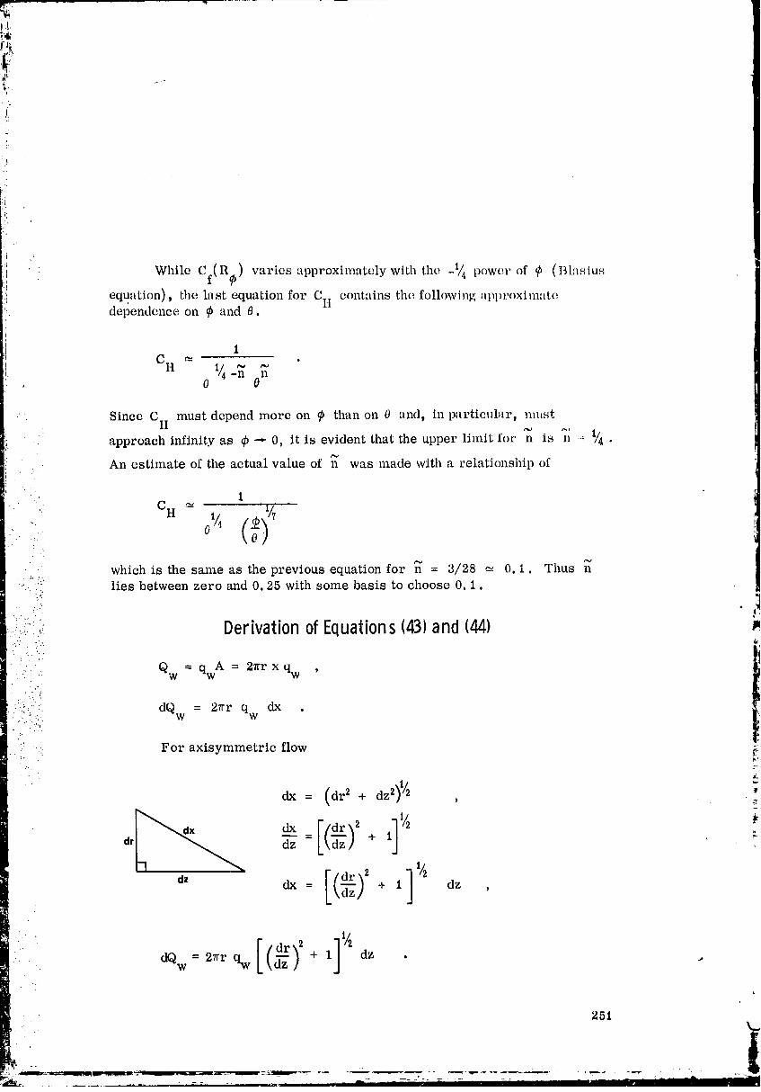
¸\,
i:
} While Cf(Ro) varies approximately with the _1_ power of _ (Blasius
equation), the last equation for CII contains the following approximatedependence on _b and 0.
Since C H must depend more on _ than on 0 and, in particular s nmst .i
approach infinity as q5-.. 0, it is evident that the upper limit for n is n -_ _/4•
An estimate of the actual value of _ was made with a relationship of
1
, CH -• o" /04which is the same as the previous equation for n = 3/28 _- 0. i. Thus n
....._":: lies between zero and 0.25 with some basis to choose 0.1
..:_,:.:;. DerivationofEquations(43)and (44) )_... ....
Qw = qw A = 27rr x qw '. .'" . ..
' ::_:!' dQw = 27rr qw dx .- ./7:....
:' -.: For axisymmetric flow _;
: /.
(aedx= + d ,
a, _ kkdz! + 1 "-
L\ '1-(£3' ]'/_dz dx = "'dz" + 1 dz ,
dQw 27rr qw \dz / + 1 dz .
251
O0000005-TSD01

0
For two-dimensional planar flow
',IV
_-'-" L\dz / + 1 ,i: dz
L,:
ldx= + 1 dz ,/
[/dY_ 2 11/2dQw= 2_rr qw L,,d=,,+, _z , (r--.)Qw = 27r fr qw + 1 dz_.- o Lx_/ '
:::" Therefore dividing by 27rr yields the heat transfer per unit width t
Qw= f % _ + 1 dz . (44) •O
Derivationof Equations1451through1471 ....,.i_
The total drag along a surface is represented by
p U2 tD=%.2A- . .. .
For axisymmetric flow the drag in z-direction can be determined if the•angle between the wall and the z-direction is known.
ii
252 _
!
00000005-TSD02

t,
drtan a - dz '
l
dx
dr 1
_._ _ .'. cOS(_ =dz Fx +
A = 2?rr X ,
D = 2 r_Cf p U2 x ,
The force inz-directionis
F = F cos a ,z x
dD = 27rr Cf p U2 cOs_ dx '
_i lm
' +I dz ,
/dz) + 1 cosc_ dz .
z
P U2 _ + 1 cos a dz • (45)D= f 2_rcf7 L\dz/0 )'
For two-dimensional planar flow }
r.-*_
2_r _ co
Dividing tlm uquaLion by 2_rr the drag per unit width is determined.Furthermore
t)
253!
00000005-TSD03

Y dx = -I 1 dz .a \dz]
!
z
The, dr'tg in axial divee, tion is
, 1F,_ --.f' cf ' t1_ \d,. + 1 _o__ ,1,, . (4_)O
The drag nornml to the axial direction is
F =f cfPu 2norm _ \dz] + 1 sin oz dz . (47)0
VelocityandEnthalpyProfilesRelatedto Equations(48)and(50)
BOUNDARY LAYERVELOCITY PROFILE
x i1/n-_(_)U for y _<_<5 (48)
BOUNDARY LAYER ::.HoI ' } _j ENTHALPY PROFILE _.
t o- Hw = flY) .. :
A Y _- I _/h o = flY)
// /// / / //1/11/11 __ X
o w= for y _ A (50)H -HO W
00000005-TSD04
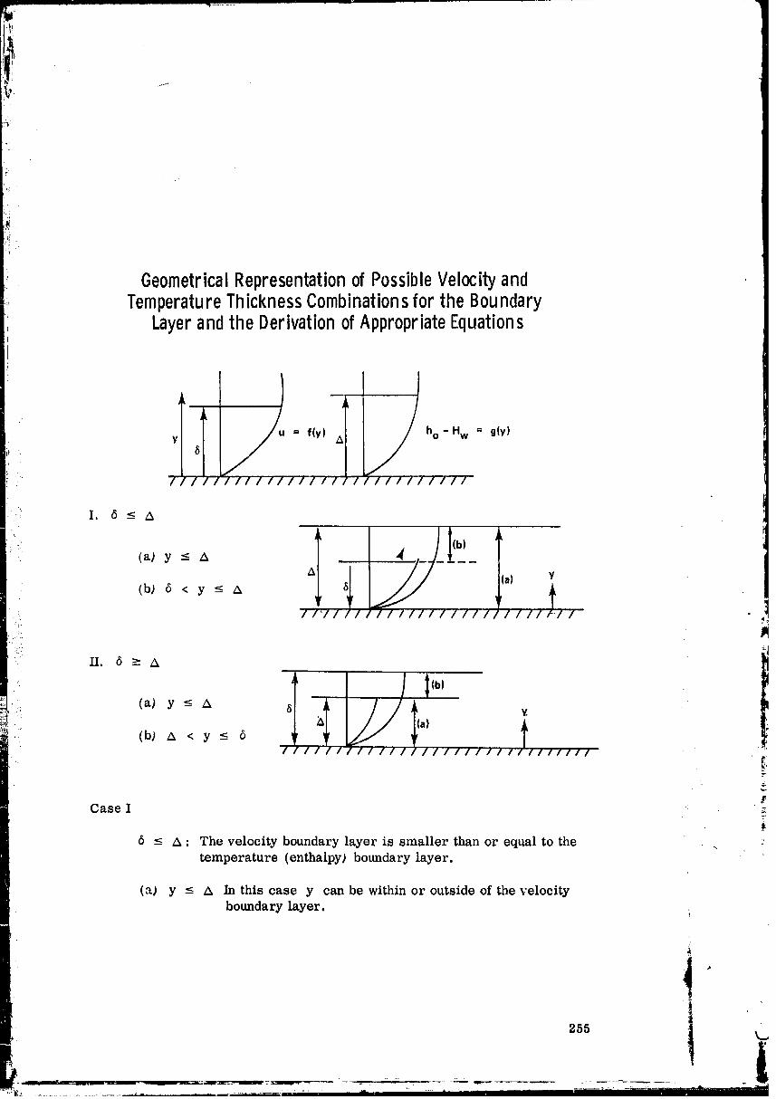
GeometricalRepresentationof PossibleVelocityandTemperatureThicknessCombinationsfortheBoundary
LayerandtheDerivationofAppropriateEquations
y f(Y) A8
.... 7, //, f////// '/_//, , t//Ill/Ill
' I. 6<-A
---/7 ,. ,:!.
II. 6 ->A
• .. (a) y-< A 8 -._. a)
_ : (b_A < y ___6 _,i.i
////////////////////////////// !i
Case I
5 _< A : The velocity boundary layer is smaller than or equal to the , :temperature (enthalpy) boundary layer.
(a} y _< A In this case y can be within or outside of the velocity
boundary layer, i
255 k=,
00000005-TSD05
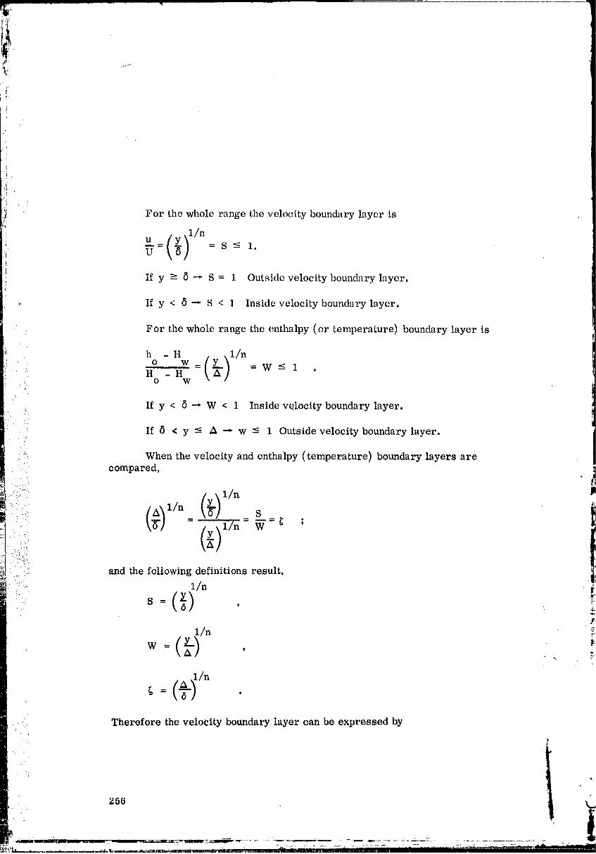
!.__:
'L
For the whole range the velocity boundary layer is
u(_),_m= =S-- < 1.U
If y > 8 -,- S = 1 Outside velocity boundary layer.
,, If y < 8 --* S < 1 Inside velocity boundary layer.
For the whole range the enthalpy (or temperature) boundary layer is
h - H .__.l/no __,y,=w__,H -H \A]
: o w
• . If y < 5 _ W < 1 Inside velocity boundary layer.
i!i If 6 < y -< A -,. w -- 1 Outside velocity boundary layer.
When the velocity and enthaipy (temperature) boundary layers are
compared,
(_),_(_)s= 1/n W _ ;
i:::('i and the following definitions result.
• .: S -_ I £
y 1/ ';n
kA/
Therefore the velocity boundary layer can be expressed by
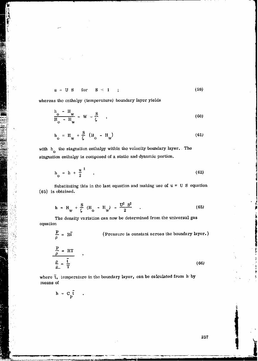
'i
,i
u = U S for S -_ 1 ; (59)
whereas the enthalpy (temperature) boundary layer yields
h - Ho w S= w =- (60)
h -n g 'O W
h = H + S Hwo w _- (no - ) (6t_
with h the stagnation enthalpy within the velocity boundary layer, Theo
stagnation enthalpy is composed of a static and dynamic portion.
tl 2.. h = h + - . (62)
o 2
• Substituting this in the last equation and making use of u = U S equation
....-. (65) is obtained.
/.:: : h H + S U2 S2 ".2i:". " = w _ (Ho - Hw ) 2 " (65) p::.'.
i, !ii The density variation can now be determined from the universal gas
• • . equation
: P R[ (Pressure is constant across the boundary layer. )• f... _. P
Z? P '
P _ [ (66)p__ T
,
where _, temperature in the boundary layer, can be calculated from h' by . , :-means of
h=C_ .P
')-57
!
00000005-TSD07

However the results are only valid for
S -'¢ 1
1W _ -
(b) 5 < y < A In this case y is greater than the velocity boundarylayer but smalle.r or equal to the temperature bound-ary layer.
: For this range the velocity boundary layer is
o--= = 8 = i (69)
J.i The second integral of equation (75) is zero since it considers a portion
: outside the boundary layer, whereas the first integral is modified according to
_: s=(Y;/n ,
.. 851/n 1/n= y _....: -..
_. sn6:: = y ,i .."_"
_ dy nsn-1: ds '
• nsn-16dy = d8 , _'
and finally reduces to
1 -
o= nf 2s n "o P (1 - S) 6 ds • \ (76)
In order to obtain the equation for the displacement •thickness 5*, therelationship used in the derivation of equation (76) is used. Furthermore the
.. first integral on the right-hand side of equation (80) is evaluated.
ti
258 t "
t
00000005-TSD08
and the result appears in equation (81). In the third integral on the right-handside of equation (80) the relationship
U
U
.. :
is applied since y is greater than the velocity boundary layer.
To obtain the energy thickness in equation (85), use is made of the
relationship as de,eloped for equation (76_. Furthermore the following rela-
":' ::" tion is applied..'.. '7
".......'"" S = W_ ,
:" '": ds: ::: dw - _ '
"/ ds = _ dw .
.... : Case II
:..-!
6 _ A The velocity boundary layer is equal to or greater " _.
.... than the temperature boundary layer.
(a) y --- A In this case y is smaller than or at the most equalto the temperature boundary layer. _,
(b) A < y _ 5 Here y is greater than the temperature boundary
layer but smaller than or equal to the velocityboundary layer.
Equation (101) is equal to one because y is outside the temperatureboundary layer.
259
!
00000005-TSD09

T _
_ For the momentum equation (106), the relationship shown in connectionwith equation (76) is utilized.
Also equation (11.1) representing the displacement thickness 6' uses
the relationship applied in equation (76). The first integral on the right-handside is solved and results in
1 1
' f nS n-1 ds = Sn = 1 .O o
For the momentum equation leading finally to equation (116), the
second integral is equal to zero since it represents a quantity which is outsidethe temperature boundary layer. The first integral on the right-hand side is
: reduced by substitution of the relationships developed in equations (76) and
(85) resulting finally in equation (116).
Thrust Degradation
'. In a real flow the boundary layer and its viscous effects cause an Isp
degradation. Furthermore, the potential flow field is narrowed because of the:':_ presence of the boundary layer.
" (i)
I ...... CHANGEDPOTENTIAL
:" VISCOUS EFFECTS
Subsequently the derivation of the equation representing the degradationof thrust caused by the viscous flow effects in the boundary layer is presentedin the following diagram, where p represents a conto_tr of the potential (invls-
cid) flow and r represents a contour of an exactly equivalent viscous flow suchthat the pressure P along the normal to the wall y is the same on r as onp and the mass flow through r-n is the same as through p-n. Thevelocity distribution is confined between n - r.
260I
O0000005-TSDIO
z
: . 7/ a• " _ " g g05(2-
. " :.:':.'":._' The mass flow rate of the potential flow through the area between p• " .... and n is"':'. 'i • ." ",.
!
_n = 2_r5 Up . 1
., p P
• ,..._ :.. The mass flow rate of the viscous flow through an area between r and n is .
?:!:"; fil = 2_r6' Upi- " ': -..';;.; .". °,. ;? _.. r r
'"" ::i However U and p are varying with y such that•"" " "1
. ..- ,_
5 Up = j pu dyr o
and6'
fi_ = 27rr f r _ dy .ro
.. .. . /.
.. 261t
!'i
00000005-TSD11
?
:ii
i_ii_
_! The momentum flux in z-direction is
!i
ii
I_iZ = fi_UZ
such that for the potentt:d and viscous flow one obtainsi
'_ (]_p) z = (27rr 5'p Ups) (U cos c_)
6'
(Mr) Z = 27rr fr _ cos a dy .o
Because of the definition, _ is assumed to be constant between n and r,
6'
because _ << 1; therefore,r
6'
(l_Ir) z = 2vr cos e., fr 8_2dy• ": _ 0
Since the same mass flows through n - p and r - n, one obtains
.!"
i. fa =ah ,•:..... p r. :.":.:: '
• .. _!
_. 2_rr6' Upco = 2,_r fr_ dy _ :P o
_,_fr .----rr?udyP o _'_
Subtracting 6' on either sider
6 t _
_, _ _, _. _, . fr ou dy" r p r pU
O
or
I:.r
p
iS1 8 1 --m
, , f,. /,. p.6 - 6 = dy - dyr P o o p,, U
w
1
O0000005-TSF01
o p U p U'/
--( )= 2_rp IT2cos a f r 1 a dyo p U U
m:
The integral expression however represents just the momentum thicl_mss asderived in equation (12).
O = - -- dy .o p U U
..: Therefore
(l_i) - (_) = 27rrp U2 cos a 0 .pz rz _"
. ..:q
Since the momentum flux is equal to the forces-_:
%':;: ' one i
" .;. _
: ....... and the forces F can be expressed by pressure P times area A
•: .... F = PA
" ' obtains. -/ -
l_I= PA . il£
Differentiation yields for the z-direction ._
dl_ dP dA_=A + P-- • :-dz _" dz
Assuming that the variation of the cross-sectional area at a station z to be
very small and negligible results in
r dlgl dP
• .:. dz dz#
264T"
O0000005-TSF02
For the potential flow
!
i A = 2vr5 ,p
t t
A = 27rr5 = 27rr6 cos _ .z pz p
For the viscous flow
!
A = 2_r6 r ,
! !A = 21rr6 = 27rr6 cos _ .
. Z rz r...
• Furthermore the shear forces must be considered for the viscous flow with '
:" t
T A = _nu = I_I .W
in this case the surface area along x must be considered
/iiii: :i• ; A = 2_rx .
Differentiating the momentum equation yields
dl¢/I dx-- 2_r --dx = "rw dx '... ',-
- " dI_
.. dx - _ 2_r . _'
Using the previously derived relationships results in the foUowing .,
momentum equation in z-direction?.
d (l_Ip)z , dP "= - 2_r5 cos _ -- .dz p dz
(A negative sign was chosen since the pressure decreases with increasing z. )
_: d (51 r) z , dP= - 2_r6 cos _-- 2_r _ .
dz r dz w
,t,i
265 i ¥
O0000005-TSF03
: :. i [lsing the previously derived relationships yields
i (g41,)z - (tCir) z == 2_rp _U 2 cos a 0
,: for the potential case results in
(I (_I)
pz d [(l_ir ) . ] ' dPdz - dz z + 27rrp_U 2 0 cos ot = - 27rr (6r - 5':') cos a d'-_ ......'
- Subtracting the equation representing the viscous case
d(M)_ _ _ dPr z
-z_ru' cos _ 2 r_ T" dz r _zz- w
from this one yields
;. :':
"" dP _!d U2 _) 2_rr6" cos ot _-_ + 2_rr _w: _.. dz (27fro_ 0 cos =
""" dz
•.:"".::'..,'.; Multiplying the equation by _- results in
. ." • ...
• _ d (rp U2 0 cos c_)= rS*• eo_ _ dP + _" "r dz•. ....• . •, .. _ .'.. W
•:.:..'::i-.
Solving for the r term and integrating result in
-. W i''_' " i.'
f r'r dz: f d(rp U2Oeos_)_f_O*cos_d_
According to a previous derivation, the force acting on the exit plane is for-
l0 Potential flow
A
(Fp) = _ U + P A + J(ep P dAze c c A P
c
• 266
O0000005-TSF04

i_ 2. Viscous flow with the inclusion of shear forces
Yi
A A
F r = _nU+PA + ferpdA .for dA'( )ze c c r w _" 'A Ac c
, (The subscript c refers to chamber.)
The degradation in force caused by the viscosity and the shear forcesis equal to the difference between the potential and the viscous flow
A A. . .: ..
(AF) ze = (Fp) ze - (Fr) ze = fep_ dAp _ ferp dAr:..:: A Ac c
•:- for dA'" + T .W T
• " A
u• ;'... 3
• ' :..... The change in area normal to the z-direction as a function of z is
:(:::,:.:)i::":i!ii dA = 27rr dr , dr "
....... t- °'__ dr dr_' '_ '" dA = 21rr -- , ___:"Jdz dz
)?:!•:.). ::•• _'_dz
•_ ..% ._
dr
•': i'.=i ,.:
For potential flow .
dA = 27rr dr.-- dz .dzp
267
O0000005-TSF05
li:b'i .
i:i
. " For viscous flow
dA = 2_r(r + 6" cos a) d(r + 6* cos a)dzr dz
For shear forces
dA t = 21r(r + 6* cos _)dz .T
Introducing these expressions in the previous equation yieldst:
z
z dr "fep2v(r + ) dz= leper dz 8' d(r + 6* cos a)(A F ) z _zz cos oL dze o o
i_!i
!
j
(i;i . :
• In the last equation the following terms can be expressed differently.
dr d(5* cos a) d (r6* cos a) ,6" cos a _+ r dz = d-_
d(6* cosa)= llc._z (6,, cos, _)1 ,6" cos a dz
.. such that
e d a) + cos 2 a ) dz= - 21rP (r6* cos --(AF) z 2 dz
'_. c 0
z
+ fe 27r w (r + 8" cos a)dz .W• " O
i,
" _* cos O/-" Since terms of << 1, they can be neglected especially when higher
r
:_"'";:.. order-terms are used.
. (,:
fe fe w i
:':':"::: (AF) = - 21rp d (r6* cos a) + 2 r Irr dz . _.Ze o o
::...... The previously derived expressions on page 266'
I.:: " f r • dz : f d (roooU2O cos a) - f r6* cos a dP__ •
.. is substituted in the equation above, such that
z _e(AF) z = -j e 27rp d (r6* cos a)+ 2Ird (rp_ U20 cos ot) .. :e o o
z
fe cos_ 2_rr6* dP0
• t• 1
269
• _ _
O0000005-TSF07
... Combining the following integrals yiehls
f .d 11,5.eo__)+ .; ,,5. ,,o_.,_,m--,; _,(P,,5.co__) .
The cquation for (AF) can be writtenz
o
z z
o O o
z z
I I°= -2;rPr(_:' cos a + 27rrp U20 cos a .o o
" ",! Since the displacement thickness 5* and the momentum thickness O
: are zero at z = 0, the thrust degradation is obtained asi_. '"
(AF) z = (-2;rp rT* cos a + 27rrp.a U20 cos OZ)exit '.-.=,..!_ e
. i z_:or
......!:
_i'::::.;::i:..i: (AF) Ze - 27fro u_0 cos a 1 - _]Jexit
,:.:.-.:. The result is only a function of exit plane conditions.
._._......_ ; DerivationofEquation1122)
.'.:.
2:
First the term 1+ 5"/0 dU of equation (121) will be derived. TheU dz , =
energy equation states that
dh = C dtP
C -C = R .p v
O0000005-TSF08
!i
Multiplying both sides by 7 yields
T(Cp Cv) = TR '
C
,_= D ,cv
c ('y - I) = _,R -* c = --TRP P "V - 1 '
Substituting this expression in the energy equation yields
0 = ht - h2 + U_ - U] •• " 2 _ [
0 = dh + UdU .
27i
O0000005-TSF09
Eli..
: Substituting the previously derived term yields
•:, U 2
":: M = --aU or M2 = _- _!
:..._.'..
.i ii.lll and representing the speed of sound a by• .'. , '
i ..":_.:; result in. .,.:];;,.
.'::..,'
i'i: "::: M2- U2'. 3'RT
Differentiating this equation in logarithmic form yields
2 lnM = 2 lnU - In 3' - lnR - lnT ,
2 d(lnM) _ 2 d(lnU) _ d(ln_) _ d(InR) _ d(lnT)dz dz dz dz dz '
272
O0000005-TSFIO
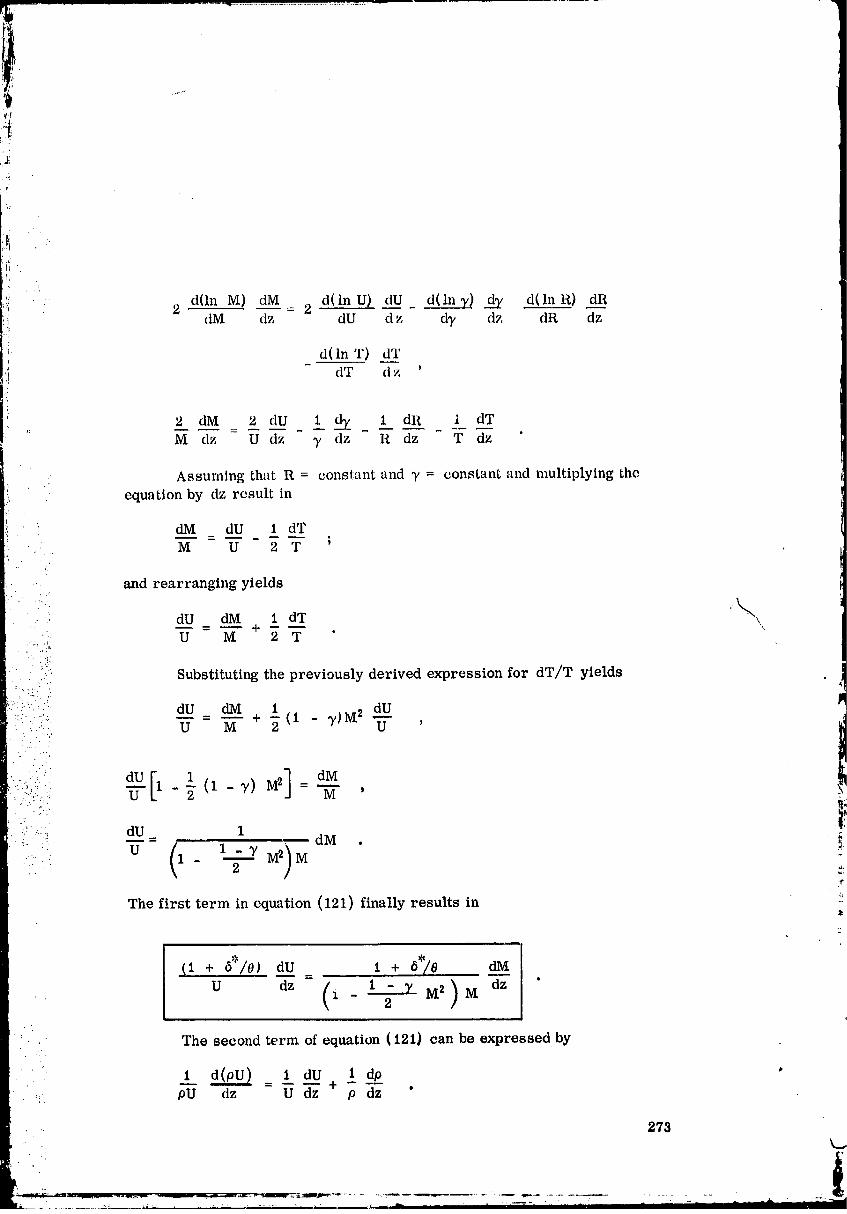
i'
_-:'! ' 2 d(ln M) dM d(lnU) dU d(lnT) d_y d(lnR) dR!; ' dM " dz - 2 dU dz dT dz dR dz
_ d(ln T) dT- dT dz '
2 ,dM 2 dU 1 dT 1_. dR i aTM dz -U dz ,/ dz R dz T dz '
Assuming that R = constant and y = constant and multiplying the
!_t equation by dz result in
dM dU 1 dTM U 2 T
and rearranging yields
dU dM 1 dT ,.k,_," ,. 'k
..:.,: U M + 2 T
• : i_.:.
.. i Substituting the previously derived expression for dT/T yields"":V -
""":" _U = _M + 2 (I - T)M 2 ---dU.. : :..: U '
•- • .......:
:. dU 1 _,_. _ = dM . .._,
. u 1- "7-
The first term in equation (121) finally results in
(I + 6':'/0) dU 1 + 6':)0
U dz- (i- 1 -T2 M2) M dz "q
The second term of equation (121) can be expressed by
1 dp1 d(pU) I dU + - -- •
.. pU dz U dz p dz
273.
O0000005-TSF11
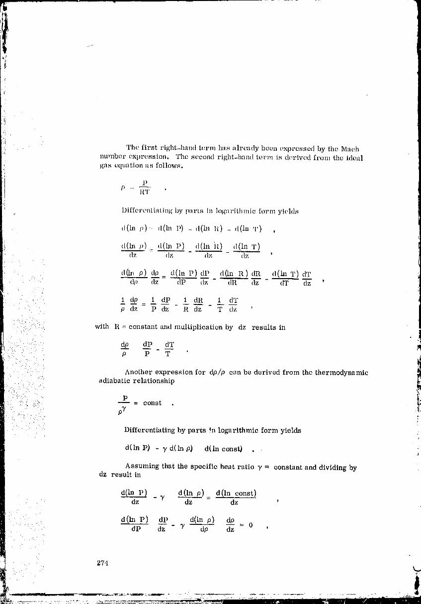
'i
¢ The first right-hand term has already been expressed by the Maeh'! nu_nber expression, The second right-hand term is d_,rivcd from the ideal
gas equation as follows.
l p
ll T
, I)iffert'ntiating by parts in logarithmic form yields
,l(ln p)== (l(ln _') _ ,l(ln I_) - d(ln T) ,
d(lnv)_ ,l(ln I') d(ln ,l(lnT)_ dz (Iz dz dz '
d(ha p) dp d(ln I') dP d(ln R) dR d(ha T) dT." dp dz dP dz dR dz dT dz '
" . .... 1 dp 1 dP 1 dR 1 dT
• " p dz P dz R dz T dz '
. ., -... " .
'. ":i:;,.:-.<.: with R = constant and multiplication by dz results in• . • ..
:: ..:-".: d__p dP dT: "-" P P T '
!',' .. .... : "
• . .-:: .. ..: ._
"- .:-: :" : Another expression for dp/p can be derived from the thermodynamic" adiabatic relationship. ..
:..,. .... "
....::'_ " - const .
• ' . .. ,'".._ :,'
•.. " . : Differentiating by parts in logarithmic form yields .-_ r
d(lnP) - Td(lnp} d(lnconst) .
Assuming that the specific heat ratio T = constant and dividing bydz result in
d(ln P) _ _' d(ln p)_ d(ln const)dz dz dz '
:: • -' d(hl P) dP d(ln p) do,. ,."
" ": '_:' ' -- - T -- 0•- - dP dz dp dz '.. ." ..
•':"..!.. ,.. 274
_--:-_..-:-:-.:.:---_ _-_.::=_-:_= _=_-r_--:--_.-___. ' ' ," " " ' '_ ...._ -='- -_- ....
O0000005-TSF13

ii •
ii" ""'" i aI-' 1 dpi_ - 0
;i P dz - _ p dz - '
dP dp
p 7 p
Final rearrangement results ini:
dP dp
p - 7 p
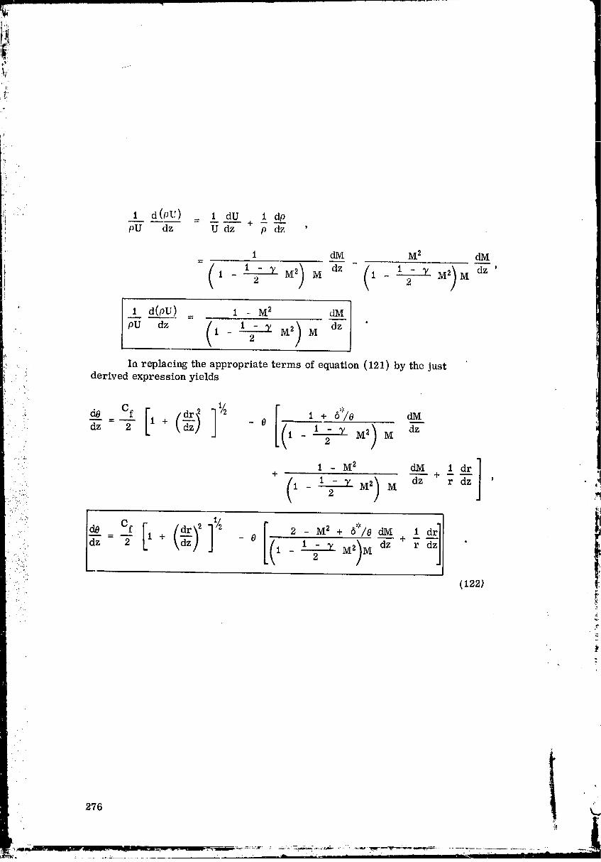
1:
•. t d(pT') _ _ dU i dppU dz U dz p dz '
1 dM M 2 dM
REFERENCES,
i. ICRPG TurbulentBoundary Layer Nozzle Analysis Computer Program,
developed by Prattand Whitney Aircraft. InteragencyChemical Rocket
PropulsionGroup, East llartford,Conn., July 1968.
2. Thiebahr, W. H. ; Kays, W. M. ;and Moffat,R. J.: The TurbulentBoundaryLayer: Experimental Heat Transfer With Blowing, Suctionand Favorable
Pressure Gradient. Report No. HMT-5, Thermosciences Division,Depart-
ment of Mechanical Engineering,StaldordUniversity,Stanford,Calif.,April 1969.
3. Tromblay, J. E. : Calculationof FrictionDrag in Rocket Nozzles andDemonstration of The EffectUpon SpecificImpulse. Rocketdyne Memo
: ADM 61-13, J_nuary 1961.
• 4. Eckert, E. R. : Survey of Boundary Layer Heat Transfer at High Velocitiesand High Temperatures. WADC Technical Report 59-624, Wright Air
Development Center, Air Research and Development Command, U° S. Air: Force, Wright-Patterson Air Force Base, Ohio, April 1960.
•:.....:
::::,::i.... 5. Eckert, E. R. : Survey on Heat Transfer at High Speeds. Report No. II. • ..
•: ARL 189, Aeronautical Research Laboratory, Office of AerospaceResearch, U. S. Air Force, Wright-Patterson Air Force Based Ohio,
• ..'
December 1961.
' .... 6. Cebeci, T. : Calculation of Compressible Turbulent Boundary Layers with
:: Heat and Mass Transfer. AIAA Paper No. 70-741_j_1970.
_ 7. Cebeci, T. ; Smith, A. ; and Mosinskis, G. : Calculation of Compressible '::
Adiabatic Turbulent Boundary Layers. AIAA Paper No. 69-687, 1969.
,%
8. Brott, D.L.;Yanta, W. J.;Voisinet, R. L.; and Lee, R. E.: An Experi-mental Investigation of the Comp_._essible Turbulent Boundary Layer with La Favorable Pressure Gradient. AIAA J., vol. 8, No. 7, July 1970,
pp. 1270-1274.
9. Lee, R. E. ; Yanta, W. J. ; and Leonas, A. C. : Velocity Profile, SkinFriction Balance and Heat Transfer Measurements of the Turbulent
Boundary Layer at Mach 5. Proceedings of the 1968 Heat Transfer andFluid Mechanics Institute, 1968, pp. 1-17.
277 z
00000005-TSG03
J:
iS:
REFERENCES(Concluded)
10. Spence, P. A. : Velocity and Enthalpy Distributions in the Compressible
Turbulent Boundary Layer on a Flat Plate. J. Fluid Mech. t Vol. 8, 1960,
pp. 368-387.
11. Coles, D. E.: The Turbulent Boundary Layer in a Compressible Fluid.
Report No. P-2417, The Rand Corporation, Santa Monica, Calif., August
22, 1961 (Also R-403-PR, A report prepared for U. S. Air Force Project
Rand, September 1962).
i 12. Hirshfelder, J. O.; Bird, R. B.; andCurtiss, C. F.: Molecular Theory
of Gases and Liquids.• John Wiley & Sons, New York, 1954.
_ 13. Elliott, D. G.; Bartz, D. R. ;and Silver, S.: Calculation Turbulent
: Boundary Layer Growth and Heat Transfer in Axi-Symmetric Nozzles.
JPL Technical Report No. 32-387, February 1963.
• _ !
• • •: L
.-
278 ' k..
I
00000005-TSG04
ti
!:
APPROVALi
!
SUPPLEMENTTOTHEICRPGTURBULENTBOUNDARYLAYERNOZZLEANALYSISCOMPUTERPROGRAM
By Satoaki Omori, Klaus W. Gross,and Alfred Krebsbach
The information in this report has been reviewed for security classification.
Review of any information concerning Department of Defense or Atomic EnergyCommission programs has been made by the MSFC Security Classification Officer.
This report, in its entirety, has been determined to be unclassified.
This document has also been reviewed and approved for technical accuracy.
"?"
HANS G. _AUL
Chief, Propulsion ..
and Thermodynamics Division
I
_L.L. _K. L. HEIMBURG "_Director, Astronautics
Laboratory
_.U.S. GOVERNMENT PRINTING OFFICE. 197Z--746--885/4098 Region 4
00000005-TSG05