lhc crab cavities - · pdf fileprepare a proposal to doe to fabricate a limited scope cavity...
TRANSCRIPT

LHC
LHC Crab CavitiesRama Calaga, CERNDOE Review, Jul 9, 2012
Review comments & Crab workshop summary
Next steps towards a prototype cryomodule
SPS tests preparation
Executive Summary & Recommendations:
Work with CERN to develop specifications and realistic R&D plan with goals
Complete ODU-SLAC design merge (and Quarter wave cavity)
Prepare a proposal to DOE to fabricate a limited scope cavity
Comments:
Adequate funding needed to gain ground on prototyping to stay on course
Increase LARP funding in the next few years to have a significant payoff
DOE Review, Jun 2011

RF/beam tests … before an LHC installation should be carried out in the SPS. Target for the SPS tests is 2015 and no later than 2016.
Important additional tests require a Point 4 setup with LHC beams.
Collaboration on SPS & P4 test cryostat development (& construction) is a priority. Joint CM design will be set up, involving cavity designers, CERN and outside cryo experts.
Further studies for machine protection with crab cavities with realistic RF failure signals in conjunction with the upgraded collimation system are required.
Full summary:https://indico.cern.ch/materialDisplay.py?materialId=paper&confId=149614
Crab Workshop Nov 2011Executive Summary: Myers/Collier
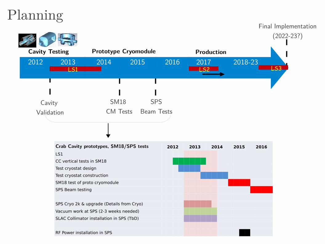
Planning
Cavity Validation
SPSBeam Tests
Prototype Cryomodule
Final Implementation(2022-23?)
Production
LS1 LS2 LS3
Cavity Testing2012 2013 2014 2015 2016 2017 2018-23
SM18 CM Tests
Crab Cavity prototypes, SM18/SPS tests 2012 2013 2014 2015 2016
LS1
CC vertical tests in SM18
Test cryostat design
Test cryostat construction
SM18 test of proto cryomodule
SPS Beam testing
SPS Cryo 2k & upgrade (Details from Cryo)
Vacuum work at SPS (2-3 weeks needed)
SLAC Collimator installation in SPS (TbD)
RF Power installation in SPS

Voltage = 3 MV/cavity (2-3 cavities /module)
Frequency = 400 MHz
Qext = 106, R/Q ~300
Cavity tuning/detuning ~ ± 1.5kHz (or multiples of it)
RF power source = 60 kW (< 18 kW nominal)
Beam current ~ 0.5-1 A
β-functions at Crab location: 3.8-4.3 km
Basic Parameters
(Pressure specifications and vessel code, cavity impedance, LLRF, multipole requirements, RF power, cryogenics, tuning specifications, alignment, flanges, He-vessel, HOM power, static B-fields etc.. in a technical specification document soon)

Performance Chart
Double Ridge(ODU-SLAC)
4-Rod(UK)
¼ Wave(BNL)
Cavity Radius [mm] 147.5 143/118 142.5/122Cavity length [mm] 597 500 330-405Beam Pipe [mm] 84 84 84Peak E-Field [MV/m] 33 32 43Peak B-Field [mT] 56 60.5 61RT/Q [] 287 915 345Nearest Mode [MHz] 584 371-378 657
Kick Voltage: 3 MV, 400 MHzGeo
met
rical
RF
194 mm
B1 B2
< 50 MV/m
< 80 mT

UK 4Rod cavityNiobium cavities finishedChemical surface treatment (now at Niowave)Heat treatment and testing at CERN (Aug 2012)
ODU-SLAC Dbl ridge cavity Niobium cavities finishedBCP & testing at Niowave & Jlab (Jul 2012)
BNL Quarter Wave CavityCall for fabrication released Cavity expected before the end of the year
Present Status
LARP +SBIR/STTR
EuCARD(+CERN)

Nb rods from solid Ingot via EDM(significant material saving)
4R Prototype Courtesy: G. Burt, Niowave
Cavity shipped to CERN (end of July) for surface treatment & testing

ODU-SLAC: Double RidgeCourtesy:J. Delayan, Niowave
Jan 2012
NiowaveSTTR, Phase I/II
May 2012
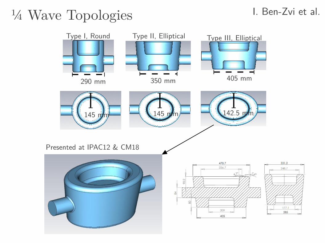
Type I, Round Type III, Elliptical
290 mm 405 mm
142.5 mm145 mm
Type II, Elliptical
350 mm
145 mm
¼ Wave Topologies I. Ben-Zvi et al.
Presented at IPAC12 & CM18

HT
HTgap
o=0-200i=0-50
HB
HTgap
i=0-50 o=0-200
Asym Vs Sym ¼Wave
142.
5 m
m ~6mm spaceVertical crossingVertical Crossing
122
mm
154 mm
3mm beam pipe
405 mm 337 mm
142.5 mm
Type III, Asym Type II, SymEpk 43 MV/m 32.3 MV/mBpk 61 mT 57.3 mTVacc 120 kV 0.0 V1st HOM 657 MHz 582 MHz
Symmetric structure to be fabricated by the end of the year
3mm beam pipe

Prototype Vertical Testing, SM18
Aim: Field tests of all 3 cavities by summer 2013Characterization of surface properties
Multipacting, optical inspection, additional processingField ramping, cycling, stability and quench margin
CERN Preparations for SM18 testsBCP of the cavities, EP is needed but not easy due to geometryHigh temp vacuum baking + HPR RF Power: Recuperating 400 MHz tetrodes used for LHC-RFCryo: Existing (2-4K) + a new dedicated 2K cryostat in 2013Instrumentation: RF, second sound, T-mapping & optical LLRF & services: Mostly exist from present testing

H. Padamsee et al., PAC95Example: Cavity Quench
Transient cavity Q meas. from high power RF pulses → thermal breakdownNominally performed during cavity processing (Tstart 2K)Determine the “ Hc
RF ” limit for 2K
LARP contribution to either quench studies and/or machine protection, highly desired
~150 s (2 turns)
Operating field
Breakdown field lower close Tc
~50 s (1/2 turn)

ISO4ISO5
ISO4/5
HPR
UPW
ISO5OIHIE-ISOLDEISO5
Optical Telescope
CERN SM18 Facility & Upgrade
T-Mapping + 2nd SoundTest Stand
Courtesy: J. Chambrillon, K-M. Schirm
3D bead-pull

Low
Field
High
Fiel
d
MultipactingM
ediu
m F
ield
SLAC codes to compare three cavities (Z. Li)Benchmark with measurements
4-Rod Double Ridge Quarter Wave
17 M
V/m
12 M
V/m
7 M
V/m

mTm/mn-1 MBRC 4-Rod Pbar/DRidge ¼-wave
b2 55 0 0 114
b3 7510 900 3200 1260
b4 82700 0 0 1760
b5 2.9x10⁶ -2.4x10⁶ -0.5x10⁶ -0.2x10⁶
b6 52x106 0 0 -1.7x10⁶
b7 560x106 -650x106 -14x106 0
RF Multipoles Courtesy: A. Grudiev et. al
Q ~ 10-3
~ 10-3
Like IR magnets, higher order components of the deflecting field importantLong term simulations underway to determine tolerances

Power Couplers
Power requirement ~60 kW (only ~18kW in operation)Peak power handling up to 250 kWInner conductor to >20 mm (50 Ω)Air cooling with disc/cylindrical windows
RF system developmentWaiting for final cavity interface from designersCERN (E. Montesinos) will develop power coupler + interfaces
Expect 2-3 year development+procurement time50 kW tetrodes at 400 MHz already available for SM18 tests
IOTs (TV Transmitter)Light Sources
Tetrode (SPS)400 MHz, ~50kW

HOM probe
Input
HOM Broadband
LOM
3-5 stage ChebyshevHigh pass filter loops
HOM Damping
4 Symmetric couplers on the end caps
(2-stage high pass)
Symmetric HOM/LOM couplers on cavity body
Approx: R/Q=200 → Qe<1x10³

Cavity Tuning
Push/pull on cavity ridges
Scissor jack type mechanism
CEBAF Tuner
SM
In operation ± 3kHzStatic: ~100 kHz
Cold stepper motors
Push/pull Blade like tuner
SM
SM
SM

He-Vessel & Tuner
Your favorite cavity
Helium TankTuner
Preliminary thoughtsSecond beam-pipe inside or outside He-vessel ?Stainless steel, NbTi or Titanium vesselPressure vessel code (some initial directives: <10L, ~1.5bar)Dynamic RF heat load ~5 watts maximumSPS tests/Point 4 in LHC → non-issue, Point 1/5 → 194mm
Beam 2
194 mmTop View
Most technical specifications to be defined in newly setup SPS working group

From LHC-CC11RF/beam tests … before an LHC installation should be carried out in the SPS. Target for the SPS tests is 2015 and no later than 2016.
ActionA formal working group CCTC is formed, 1st meeting Jul 11, 2012.
MandateIdentify/resolve constraints for testing crab cavities in the SPS. Develop full understanding of design requirements, drafting functional specifications, and set schedules and commissioning programs Input to the LHC crab cavity project through to a TDR. MembersRF, Vacuum, Cryogenics, Integration, Collimation, Instrumentation, Beam dynamics, Machine Protection

RF Helium
RF
420 mm 194 mm
Cryomodule, BC
SPS Tests Point 4 Tests Final Scheme
2nd beam pipe cold
3rd spare
Make these two compatible

Cryomodule Development
High priority to start joint effort with US and European partners
ActionsInitial concepts in 6-8 months (FNAL, SBIR, Triumph, CEA-CNRS)Immediate task to identify constraints (environmental & RF)Engineering meeting at the end of 2012 for conceptual review
Some initial work done for elliptical cavitiesFNAL (Y. Yakovlev et. al), 2010 ODU-Niowave: SBIR, Phase I

4 LHC Cavities in SPS
RF Power
SPS, BA4 Setup (1998)
Y-Chamber like, similar to present COLDEX
Courtesy E. Montesinos
50 kW Tetrode
Cryo-Line
Crab cavity test setup in SPS will look similar

LSS4, COLDEX
Cavity validation with beam (field, ramping, RF controls, impedance)Collimation, machine protection, cavity transparency, RF noise, emittance growth, non-linearities,
Cryogenics, RF power, cabling and installation services (some during LS1)
Milestone 3: SPS Tests foreseen 2016

Temp Choice → 2K Baseline
2 K, add 150 kCHF(Heat exchanger + JT valve + ..)
Capacity: 0.7 g/sMeasured capacity by the end of 2012
4.5 K, 300 kCHFCapacity: 0.1 g/s, measured capacity 120 W.

LARP Crab Request
FTE/Hardware FY12 FY13 FY14 FY15 Total [k$]BNL 0.048/0.349 0.144/0.508 0.144/0.4 0.4 0.336/1.657
FNAL 0.155 0.565 0.5/0.25 0.5/0.25 1.565/0.5
(ODU) 0.245/0.1 0.245/0.4 0.245/0.4 0.4 0.735/1.3
LBNL 0.096 0.096 0.051 0.051 0.294
SLAC 0.15 0.15 0.15 0.15 0.6Total [M$/yr] 1.143 2.108 2.140 1.751 6.987
Details on FTE/yr BNL : 1.0 Postdoc (B. Ping) + 0.2 FTE (Q. Wu) + In kind (Ilan+Sergey)FNAL: 1.0 Student (Bruce Yee) + 1.5 FTE (cryostat) + 500k for cryostatODU: 1.0 postdic (Julius Nfor) + 1 Student (S. DeSilva) + In kind (Jean)LBNL : 0.25 postdoc (Stefan Paret) + 0.15 FTE (ji Qiang) + travelSLAC: 0.5 FTE (Zenghai)
Outcome → 4 cavities (all dressed) + 1 cryostat(outside contributions: FPCs + 1 cryostat)

Global FY12 FY13 FY14 FY15 FY16 FY17-21FTEs [yrs] 13 16.25 20.3 9 7.3 75.5
Mat [MCHF] 3.6 575 7.1 3.55 3.7 66.1
Breakdown: Material in MCHF & [FTE]
CERN-RF* 0.713 [1.0] 2.00 [2.5] 4.00 [2.5] 2.00 [4.8] 3.0 [5.0]
USLARP 0.043 [2.3] 0.87 [4.0] 0.92 [3.6] 1.00 [2.3] [tbd]
UK-LU/DL 0.200 [2.4] 1.05 [1.5] 1.05 [1.5] 1.05 [1.5] [tbd]
CEA-CNRS [0.5] [2.0] [1.0] - -
Estimate/Breakdown[MCHF]
* Note: Some CERN spending not included in distribution(Infrastructure, cryogenics and services)
Cavity Testing SM18 SPS TestsCryomodule

Next Steps
Cavities, end of 2012Two prototypes at hand and 3rd to come soonCavity testing is the immediate focus → 1st milestone (end of year)
Cryomodule, end of 2014 High priority to establish a joint effort NOWCollaborations: N.A. (FNAL, Triumph) & Euorpe (CEA-CNRS/IN2P3)Focused meeting at the end of year to review conceptual designs
SPS Tests, end of 2015CERN working group for complete integration (1st meeting Jul 11)Preparation (cabling, RF etc..) in SPS already starting in LS1

Pressure sensitivity & pressure vessel codeCavity stiffness < 20-30 kN/mm (tunability) Sensitivity ~ 100 kHz/mm (coarse), Resolution ~ 0.1 kHzShould we conform to higher category for safety
Mechanical alignment tolerancesLongitudinal alignment at the level of -beta (voltage compensation)Transverse alignment < 100 microns (power compensation)Tilt alignment (residual x-angle in the other plane, few rad)
Some More Parameters

LHC RF Distribution
~300m
LLRF (Strongly coupled feedback)
P. Baudrenghien
Independent high power RF (60 kW → IOTs)
Cavity 1Cavity 2
Track cavity 2 drop in voltage
Crab cavity servo controller
(Primarily a CERN activity)

~ 1mm displacement for 4mm thickness
~ 0.1mm displacement for 4mm thickness
Vibrational modes are 450 Hz and above but detailed simulations underway
The ridges area needs to be constrained against pressure fluctuations ~ MHz/mm
Cavity Sensitivity
Vibration of flat surfaces and/or change in ellipticity ~MHz/mm (constrain with stiffners)
Operation is CW like, voltage is only slowly ramped up (hours)Lorentz force detuning → probably non-issueMicrophonics → Stiffners, should we consider fast tuning?

Impedance Thresholds
Longitudinal impedance2.4 M total (7 TeV)
Strongest monopole mode:R/Q=200 → Qe<1x10³
Damping → Qe < 100-500
Transverse
Courtesy: Burov, Shaposhnikova
HOM
HOM
HOM
HOM
Crab
Strongest dipole mode:Z < 0.6 M/m (0.58 GHz)(Qext = 500)
Longitudinal

Module Layout, Point 1/5Case I might be preferable to equalize voltages for the two beams
Machine protection → minimize cavity quench propagation Spare policy → nominally 8-modules for 2-IPs total + 2 spares
Case I
Case II
D2 Q4
3.5 m (5 m for 3 cavities)
1 T, residual fields