lg training manual - uncleharrywizard.com · lg training manual lsc27990st refrigerator info center...
TRANSCRIPT

LG TRAINING MANUALLSC27990ST Refrigerator Info Center - Fall 2007
LG TRAINING MANUAL

Published August 2007 by LG USA Training CenterCustomer Service (and Part Sales): 1-800-243-0000Technical Support (and Part Sales): 1-800-847-7597 USA Website: www.lgusa.comCustomer Service Website: us.lgservice.comB2B Service Website: aic.lgservice.comTraining Website: www.LGCSAcademy.com
IMPORTANT SAFETY NOTICE
This manual was prepared for use only by properly trained audio-visual service technicians. When servicing this product, under no circumstances should the original design be modified or altered without permission from LG Electronics. Unauthorized modifications will not only void the warranty, but may lead to property damage or user injury. All components should be replaced only with types identical to those in the original circuit and their physical location, wiring, and lead dress must conform to original layout upon completion of repairs. If any fuse (or Fusible Resistor) in this TV receiver is blown, replace it only with the factory specified fuse type and rating. When replacing a high wattage resistor (Oxide Metal Film Resistor, over 1W), keep the resistor 10mm away from PCB. Always keep wires away from high voltage or high temperature parts. Do not attempt to modify this product in any way.
Special components are also used to prevent shock and fire hazard and are required to maintain safe performance. No deviations are allowed without prior approval by LG Electronics. Service work should be performed only after you are thoroughly familiar with these safety checks and servicing guidelines. Circuit diagrams may occasionally differ from the actual circuit used. This way, implementation of the latest safety and performance improvement changes into the set is not delayed until the new service literature is printed.
GENERAl SAFETY GuIdANCE
An lsolation Transformer should always be used during the servicing of a receiver whose chassis is not isolated from the AC power line. Use a transformer of adequate power rating to protect against personal injury from electrical shocks. It will also protect the receiver and its components from being damaged by accidental shorts of the circuitry that may be inadvertently introduced during the service operation. Before returning the receiver to the customer, always perform an AC leakage current check on the exposed metallic parts of the cabinet, such as antennas, terminals, etc., to be sure the set is safe to operate without damage of electrical shock.
With the instrument AC plug removed from AC source, connect an electrical jumper across the two AC plug prongs. Place the AC switch in the on position, connect one lead of ohm-meter to the AC plug prongs tied together and touch other ohm-meter lead in turn to each exposed metallic parts such as antenna terminals, phone jacks, etc. If the exposed metallic part has a return path to the chassis, the measured resistance should
be between 1MΩ and 5.2MΩ. When the exposed metal has no return path to the chassis the reading must be infinite. Any other abnormality that exists must be corrected before the receiver is returned to the customer.
ElECTROSTATICAllY SENSITIvE dEvICESSome semiconductor (solid-state) devices can be damaged easily by static electricity. Such components commonly are called Electrostatically Sensi-tive (ES) Devices. Examples of typical ES devices are integrated circuits and some field-effect transistors and semiconductor “chip” components. The following techniques should be used to help reduce the incidence of component damage caused by static electricity.
Immediately before handling any semiconductor component or semiconductor-equipped assembly, drain off any electrostatic charge on the body by touching a known earth ground. Alternatively, obtain and wear a commercially available discharging wrist strap device, which should be removed for potential shock reasons prior to applying power to the unit under test. After removing an electrical assembly equipped with ES devices, place the assembly on a conductive surface such as an ESD mat, to prevent electrostatic charge buildup or exposure of the assembly. Use only a grounded-tip soldering iron to solder or unsolder ES devices. Use only an anti-static solder removal device. Some solder removal devices not classified as “anti-static” can generate electrical charges sufficient to damage ES devices. Do not use freon-propelled chemicals which can generate electrical charge sufficient to damage ES devices. Do not remove a replacement ES device from its protective package until immediately before you are ready to install it. Minimize bodily motions when handling unpackaged replacement ES devices (Otherwise, seemingly harmless motion, such as the brushing together of your clothing or the lifting of your foot from a carpeted floor, can generate static electricity sufficient to damage an ES device).
REGulATORY INFORMATIONThis equipment has been tested and found to comply with the limits for a Class B digital device, pursuant to Part 15 of the FCC Rules. These limits are designed to provide reasonable protection against harmful interference when the equipment is operated in a residential installation. This equip-ment generates, uses and can radiate radio frequency energy and, if not installed and used in accordance with the instruction manual, may cause harmful interference to radio communications. However, there is no guarantee that interference will not occur in a particular installation. If this equipment does cause harmful interference to radio or television reception, which can be determined by turning the equipment off and on, the user is encouraged to try to correct the interference by one or more of the following measures: Reorient or relocate the receiving antenna; Increase the separation between the equipment and receiver; Connect the equipment into an outlet on a circuit different from that to which the receiver is connected; Consult the dealer or an experienced radio/TV technician for help.
The responsible party for this device’s compliance is:
LG Electronics of Alabama, Inc.201 James Record RoadHuntsville, AL 35813, USA
Info Center
Refrigerator Info Center Training 3 Contents
Table of ConTenTsOVERVIEW ....................................................................................................5
INTRODUCTION .................................................................................................... 5TOPICS DISCUSSED IN THIS MANUAL ....................................................................... 5MODEL NUMBER ................................................................................................... 5
OPERATION ...................................................................................................6MICROCONTROLLER ...................................................................................... 15TROUBLESHOOTING ...................................................................................... 20CIRCUIT DESCRIPTIONS ................................................................................ 22

- 4 -

Info Center
Refrigerator Info Center Training 5 Overview
overview
INTROduCTIONThis portion of some of our refrigerators allows the customer to view the weather present and forecasts for the next five days. It also stores images and recipes for a variety of foods, has a calendar that can be programmed for a variety of reminders such as birthday and anniversaries. It also allows the refrigerator and freezer temperature to be set by the customer without opening the door. This device also displays an error code in case of a failure within the product. In this manual you will find the functionality and operation of this display as well as troubleshooting for this option as well as for some other options.
OPERATIONWhen your refrigerator is first installed, allow it to stabilize at normal operatingtemperatures 2~3 hours prior to filling it with fresh or frozen foods.If operation is interrupted, wait 5 minutes before restarting.
About defective pixelsThis LCD display contains hundreds ofthousands of individual pixels. LCD displaystypically contain a small number of pixels that donot function normally. Your display has beeninspected and is in compliance withmanufacturer’s specifications, indicating that anypixel defects do not affect the operation or useof your display. On a display of this size, 4 orfewer defective pixels are considered to benormal and are not grounds for exchange orrefund.
TEMPERATURE
DISPENSER
MENU
SELECT
Dispenser button
Menu button
Temperature buttonLock button
Calendar / Anniversary / Reminder
Select
Dispenser light button
Door alarm button
Setup
Adjusting the temperatures and functions
Info Center
Refrigerator Info Center Training 6 Operation
operaTion
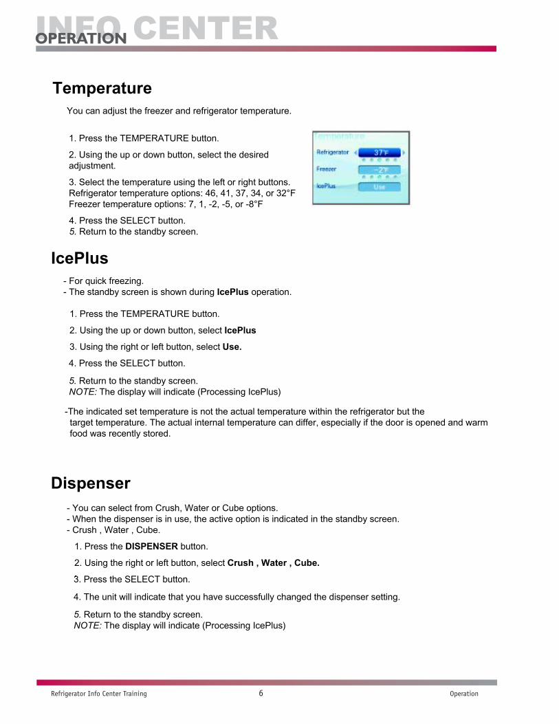
TemperatureYou can adjust the freezer and refrigerator temperature.
1. Press the TEMPERATURE button.
2. Using the up or down button, select the desired adjustment.
3. Select the temperature using the left or right buttons.Refrigerator temperature options: 46, 41, 37, 34, or 32°FFreezer temperature options: 7, 1, -2, -5, or -8°F
4. Press the SELECT button. 5. Return to the standby screen.
- For quick freezing.- The standby screen is shown during IcePlus operation.
1. Press the TEMPERATURE button.
2. Using the up or down button, select IcePlus
3. Using the right or left button, select Use.
4. Press the SELECT button.
5. Return to the standby screen.NOTE: The display will indicate (Processing IcePlus)
-The indicated set temperature is not the actual temperature within the refrigerator but the target temperature. The actual internal temperature can differ, especially if the door is opened and warmfood was recently stored.
- You can select from Crush, Water or Cube options.- When the dispenser is in use, the active option is indicated in the standby screen.- Crush , Water , Cube.
Dispenser
IcePlus
1. Press the DISPENSER button.
2. Using the right or left button, select Crush , Water , Cube..3. Press the SELECT button.
4. The unit will indicate that you have successfully changed the dispenser setting.
5. Return to the standby screen.NOTE: The display will indicate (Processing IcePlus)

Info Center
Refrigerator Info Center Training 7 Operation
operaTion
Automatic icemaker
• The automatic icemaker can automatically make 6 cubes at a time, 70~120 pieces per day. Thisquantity may vary by circumstance, including ambient temperature, door opening, freezer load. etc.
• Ice making stops when the ice storage bin is full.• If you don't want to use the automatic icemaker, turn the icemaker switch to OFF.• If you want to use automatic icemaker again, change the switch to ON.• The water amount will vary depending on the water amount selection button. Setting, as well as the water pressure of the connected water line.
NOTE:It is normal that a noise is produced when ice drops into the ice storage bin.Hold your cup in place for a couple of seconds after dispensing ice or water so thelast few drops go in to your cup instead of the floor.
Ice is lumped together• If the ice lumps together, take it out, break it apart, and put it back into the storage bin.• When the icemaker produces too small or lumped together ice, the amount of water supplied to the ice
maker needs to adjusted. Contact the service center.• If ice is not used frequently, it may lump together.
Power failure• Water may drip from the refrigerator. Take the ice storage bin out and discard all the ice then dry it and place it back. After the power is restored, the refrigerator defaults to crushed ice.
The unit is newly installed• It takes about 12 hours for a newly installed refrigerator to make ice.
CAUTIONThrow away the first few batches of ice. The first ice and water may include particles or odor from the watersupply line or the water tank.This is also necessary if the refrigerator has not been used for a long time.Never store beverage cans or other foods in ice storage bin for the purpose of rapid cooling. It may damage the automatic ice maker. Shake the bin occasionally to settle the ice in the bin. Ice may pile up just around the icemaker causing the icemaker to think that the ice storage bin is full. If discolored ice is dispensed, contact an Authorized Service Center immediately. Do not use the ice or water until the problem is corrected.WarningDo not place your hands into the water & ice dispenser opening. Doing so can result in amputation or cuts.
Info Center
Refrigerator Info Center Training 8 Operation
operaTion
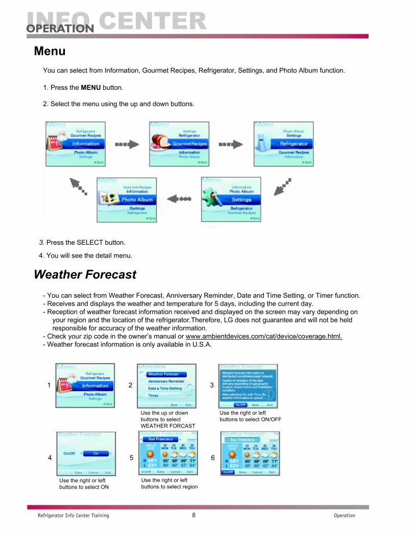
You can select from Information, Gourmet Recipes, Refrigerator, Settings, and Photo Album function.
Menu
1. Press the MENU button.
2. Select the menu using the up and down buttons.
3. Press the SELECT button.
4. You will see the detail menu.
Weather Forecast- You can select from Weather Forecast, Anniversary Reminder, Date and Time Setting, or Timer function.- Receives and displays the weather and temperature for 5 days, including the current day.- Reception of weather forecast information received and displayed on the screen may vary depending on
your region and the location of the refrigerator.Therefore, LG does not guarantee and will not be held responsible for accuracy of the weather information.
- Check your zip code in the owner’s manual or www.ambientdevices.com/cat/device/coverage.html.- Weather forecast information is only available in U.S.A.
Use the up or downbuttons to select WEATHER FORCAST
Use the right or leftbuttons to select ON
Use the right or leftbuttons to select ON/OFF
Use the right or leftbuttons to select region
1 2 3
4 5 6

Info Center
Refrigerator Info Center Training 9 Operation
operaTion
- Register the anniversary date.- Select the Anniversary reminder using the button.
Anniversary Reminder
Press the up or down button toselect Anniversary Reminder.
Select the month using the up or down button.Press the down button and then select the date using the right or left button.
Select the menu using the up or down button.
Press the down buttonto select Save.
Select the advance timeusing the right or left button.
NOTE:The alarm will go off at the set date and time, and the anniversary will be displayed in the screen.
1 2 3
4 5
View the anniversary list
Press the up or down button to select Anniversary Reminder.
Press the up or down button to select list
You can check the detail menu using the right or left button.
1 2 3 4
Date & Time setting
1 2 3 4
Press the up or down button to select Data & Time Setting.
Select the menu using the up or down buttonSelect the value using the right or left button
Press the down buttonto select Save.

Info Center
Refrigerator Info Center Training 10 Operation
operaTion
TimerTo set the alarm.
- The alarm will go off at the set time, and the timer image will be displayed in the screen.
Press the up or down button to select Timer
Select time using right or left button
Press the right or left button to select Reset
Press the down buttonto select Save.
Gourmet RecipesThere are 10 classifications of recipes under this menu
1. Use the up or down button to select the type of recipe2. Use the right or left button to select the specific recipe image3. With MORE highlighted press the Select button to view the recipe
Filter ResetYou can select from Filter reset, Door alarm, Dispenser light, Manual, and Service Call functions.Filter Reset also reminds you when to replace the filter.
Press the up or down button to select Filter Reset
Press the Select button

Info Center
Refrigerator Info Center Training 11 Operation
operaTion
Door AlarmThis is the function of notifying you every 30 seconds that the refrigerator door is open for more than 1 minute.- You can turn the door alarm on or off.
1. Press the Menu button2. Use the up or down button to select the Door Alarm3. Use the right or left to select Use or Not to Use.
Dispenser LightThis function controls the LED lamp located on the dispenser.- Press this icon turn the dispenser light on or off.
Owner’s Manual
1. Press the Menu button2. Use the up or down button to select the Dispenser Light3. Use the right or left to select ON or OFF.4. Press the down button to save.
1. Press the Menu button2. Use the up or down button to select the Owner’s Manual3. Use the right or left to select from the topics.4. Press the select button to open the topic.5. Use the right or left button to select the detail menu.6. Press the down button to select list.
You can select from Key Guide, Tem. Adjustment, Child Lock, Weather Forecast, Proper Food Storage, Fridge Maintenance Guide, Freezer Maintenance Guide or Elimination of Odor function.
Service Call info.This will show the phone number to call for service in the US and Canada.
1. Press the Menu button2. Use the up or down button to select the Service Call info.
SettingsYou can select from Display Image, Display Theme, Power Saver, Screen Backlight/Button Sound, or °C/°F Setting function.
1. Press the Menu button2. Use the up or down button to select the Settings.3. Use the up or down buttons to select the setting you wish to view or alter.4. Select Save to keep the changes that have been made.
Info Center
Refrigerator Info Center Training 12 Operation
operaTion
You can select the standby screen setting.
1. From the Settings menu. Select Display Image.2. Use the right or left button to select the image.3. Select Preview to preview the image full screen. You can still use right or left to scroll thru the images.4. Select Save to keep the image you selected.
Display Image
Display ThemeYou can select the screen theme setting.
1. From the Settings menu. Select Display Theme.2. Use the right or left button to select the Theme. Character or Motion.3. Use the down button to select Save.
Power SaverWhen selecting [Use of Power Saver], the LCD screen backlight turns off after eclipse of designated time.
1. From the Settings menu. Select Power Saver.2. Use the right or left button to select the Use or Not to Use
1. If Use is selected use the down button to access the time setting.2. Use the right or left to select how long the screen will remain lit, 1,3,5 minuets.
3. Use the down button to select Save.
NOTE:• When you select the Photo, the pictures saved in the photo album will be shown in slideshow.• When selecting Not in Use, the current standby screen is saved as Screen Saver.
Screen Backlight/Button Sound- You can adjust the screen brightness.- When selecting the button sound, you can turn the button sound on or off.
1. From the Settings menu. Select Screen Backlight/Button Sound.2. Use the right or left button to select the brightness.3. Use the down button to select the Button Sound.4. Use the right or left button to set turn it on or off.5. Use the down button to select Save.
C/F Setting1. From the Settings menu. Select C/F Setting.2. Use the right or left button to select Centigrade or Fahrenheit.3. Use the down button to select Save.
Info Center
Refrigerator Info Center Training 13 Operation
operaTion
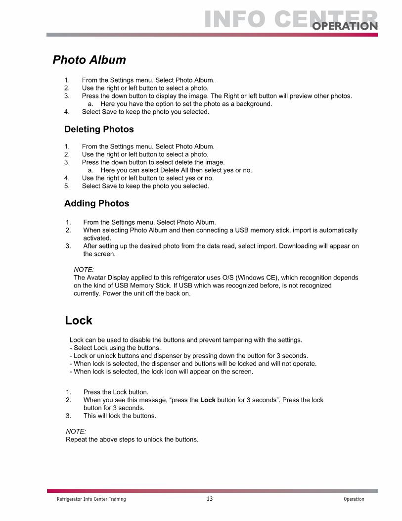
1. From the Settings menu. Select Photo Album.2. Use the right or left button to select a photo.3. Press the down button to display the image. The Right or left button will preview other photos.
a. Here you have the option to set the photo as a background.4. Select Save to keep the photo you selected.
Deleting Photos
1. From the Settings menu. Select Photo Album.2. Use the right or left button to select a photo.3. Press the down button to select delete the image.
a. Here you can select Delete All then select yes or no.4. Use the right or left button to select yes or no.5. Select Save to keep the photo you selected.
Adding Photos
Photo Album
1. From the Settings menu. Select Photo Album.2. When selecting Photo Album and then connecting a USB memory stick, import is automatically
activated.3. After setting up the desired photo from the data read, select import. Downloading will appear on
the screen.
NOTE:The Avatar Display applied to this refrigerator uses O/S (Windows CE), which recognition depends on the kind of USB Memory Stick. If USB which was recognized before, is not recognized currently. Power the unit off the back on.
LockLock can be used to disable the buttons and prevent tampering with the settings.- Select Lock using the buttons.- Lock or unlock buttons and dispenser by pressing down the button for 3 seconds.- When lock is selected, the dispenser and buttons will be locked and will not operate.- When lock is selected, the lock icon will appear on the screen.
1. Press the Lock button. 2. When you see this message, “press the Lock button for 3 seconds”. Press the lock
button for 3 seconds. 3. This will lock the buttons.
NOTE:Repeat the above steps to unlock the buttons.
Info Center
Refrigerator Info Center Training 14 Operation
operaTion
Press the TEMPERATURE and DOOR ALARM buttons simultaneously for 1 second in the locked state.
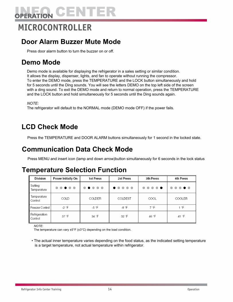
MICOM FUNCTIONDoor Alarm Buzzer Mute Mode
Press door alarm button to turn the buzzer on or off.
Demo ModeDemo mode is available for displaying the refrigerator in a sales setting or similar condition.It allows the display, dispenser, lights, and fan to operate without running the compressor.To enter the DEMO mode, press the TEMPERATURE and the LOCK button simultaneously and hold for 5 seconds until the Ding sounds. You will see the letters DEMO on the top left side of the screen with a ding sound. To exit the DEMO mode and return to normal operation, press the TEMPERATURE and the LOCK button and hold simultaneously for 5 seconds until the Ding sounds again.
NOTE:The refrigerator will default to the NORMAL mode (DEMO mode OFF) if the power fails.
LCD Check Mode
Communication Data Check ModePress MENU and insert icon (lamp and down arrow)button simultaneously for 6 seconds in the lock status
Temperature Selection Function
NOTE:The temperature can vary ±5°F (±3°C) depending on the load condition.
• The actual inner temperature varies depending on the food status, as the indicated setting temperature is a target temperature, not actual temperature within refrigerator.
MICROCONTROllER

Info Center
Refrigerator Info Center Training 15 Operation
operaTion
Outside Temperature Display Function1. The ambient temperature sensor is located under the upper right hinge cover. This sensor
reads the temperature of the room and displays it in the upper right corner of the display.2. The ambient temperature is displayed between 16 °F and 120 °F. Outside of that range, the
display will show Er.3. Since the ambient temperature sensor is located at the hinge, its reading may differ from other
thermometers in the room.
Lock Function1. To lock the display, the dispenser, and the control panel, push on the LOCK button more than 3
seconds. Lock icon is appears at the right of display when locked.2. The buzzer sound, control panel, and dispenser functions do not work when the lock is set.3. To release the lock, press the lock button and hold until the lock icon disappears (about 3 seconds).
1. There is a replacement indicator light for the water filter cartridge on the dispenser.2. Water filter needs replacement about every six months.3. You will see a reminder pop-up window in the LCD screen 2 weeks before / 1 week before /
due date to replace the filter to notify you that the filter needs to be replaced.4. If you want to reset the filter, use the Menu Refrigerator Filter Reset menu.
Filter condition display function
Dispenser use selectionYou can select water or ice.Select WATER, CRUSHED ICE, or CUBED ICE by pressing the DISPENSER button as you desire.Use your cup to press lightly on the actuator.• Each graphic is indicated on the display for the selected function.• You’ll hear a CLICK when the ice door closes 5 seconds after ice is dispensed.
NOTE: Hold your cup in the dispenser for a few seconds after dispensingice or water to catch the last few drops or pieces of ice.
ICE PLUS FreezingSelect this function to expedite freezing.• Turn on/off the IcePlus function using the IcePlus button within the Temperature function.• The "IcePlus" icon remains at the ON status after animation when selecting Special Refrigeration
IcePlus FRZ• ICE PLUS freezer function automatically turns off after a set time.

Info Center
Refrigerator Info Center Training 16 Operation
operaTion
ICE PLUS freezing1. ICE PLUS freezing is a function to increase the cooling speed of the freezer compartment by running
both the compressor and the fan simultaneously.2. ICE PLUS is cancelled and the refrigerator returns to its default setting in the event of a power
interruption.3. Selecting ICE PLUS changes only the speed of the cooling without affecting the set temperature.4. The temperature can be adjusted even when ICE PLUS has been selected and is in progress.5. The freezer operates at whatever temperature was set at the time ICE PLUS was selected.6. If you select ICE PLUS, the compressor and fan will run until it is deselected or the cycle time has
elapsed. (3 hours : compressor and fan run / 3 ~ 24 hours : COLDEST operation)7. If a defrost cycle occurs while an ICE PLUS is already running, ICE PLUS runs for its remaining cycle
time after the defrost cycle is completed. If the defrost cycle takes longer than 30 minutes, ICE PLUS will run for only 2 hours at the end of the defrost cycle.
8. If you press ICE PLUS during a defrost cycle, the ICE PLUS indicator will illuminate but the compressor will not operate until the defrost cycle is complete.
9. If you press ICE PLUS within 7 minutes of compressor cut-off, the compressor will not operate until the 7-minute delay has passed.
10. The freezer fan motor runs at high speed during the ICE PLUS cycle.
OptiFresh Function
1. The OptiFresh bin is positioned at the bottom of the refrigerator compartment and has a separate temperature control to allow perfect storage of fruits and vegetables.
2. OptiFresh comprises of OptiFresh sensor at the rear of OptiFresh and a damper between OptiFreshand Freezer compartment and a temperature adjusting display at the top of it.
3. When powered on, the initial NOTCH of OptiFresh display will be on OptiFresh Crisper. If only the refrigerator door is opened, the OptiFresh LED will be ON.
4. The OptiFresh sensor opens and closes the damper based on the temperature.5. The OptiFresh damper will cycle every hour to prevent icing up.
Control of variable type freezing fan
1. To increase cooling speed and response to load, the MICOM will vary the speed of the freezer fan between low and high.
2. The MICOM runs the fan at high speed only at power-up and for ICE PLUS cycles, and runs at low speed for all other settings.
3. If you open the freezer door, the refrigerator door, or the home bar door, and the freezer fan was running at high speed, it will reduce to low speed. If it was running at low speed when a door was opened, it will turn off.
4. If the MICOM determines the BLDC fan motor is locked up, (no signal for 115 seconds) it will show a failure code on the display and cut power to the fan. To power the fan again, unplug the refrigerator for a few seconds and plug it in again.

Info Center
Refrigerator Info Center Training 17 Operation
operaTion
1. The cooling fan motor performs ON/OFF control by linking with the COMPRESSOR.2. It controls at the single RPM without varying RPM.3. Failure sensing method is same as in fan motor of freezing fan motor (refer to failure diagnosis function
table for failure display).
Control of cooling fan motor
Door opening alarm
1. The buzzer sounds when any door is held open for more than one minute.2. After any door has been open for one minute, the buzzer sounds three times for second each, then it
sounds three times for second each every thirty seconds until the door is closed.3. When all open doors have been closed, the buzzer stops.
Audible warning operation, manual frost defrost buzzer
1. The buzzer sounds briefly when the test button on the main PCB is pressed.2. If you select manual operation, the buzzer sounds three times for 2/10 second each, then it sounds
three times for 2/10 second each every thirty seconds until the door is closed.3. If you select manual defrost, the buzzer sounds three times for 2/10 second each, then it sounds three
times for 2/10 second each every thirty seconds until the door is closed.
Defrost function
1. Defrost is cycled whenever the compressor’s runtime reaches 7 hours.2. In providing initial power (or after a power failure), defrost starts whenever total operation time of
compressor reaches 4 hours.3. Defrost is completed when the temperature of the defrost sensor reaches 41°F (5°C) after starting
defrost. Defrost ends after 2 hours even if the sensor does not detect 41°F (5°C).4. No defrost cycle is run if the defrost sensor fails.
Info Center
Refrigerator Info Center Training 18 Operation
operaTion
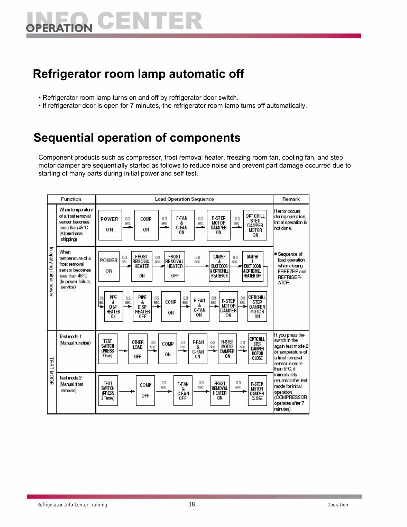
• Refrigerator room lamp turns on and off by refrigerator door switch.• If refrigerator door is open for 7 minutes, the refrigerator room lamp turns off automatically.
Refrigerator room lamp automatic off
Component products such as compressor, frost removal heater, freezing room fan, cooling fan, and step motor damper are sequentially started as follows to reduce noise and prevent part damage occurred due to starting of many parts during initial power and self test.
Sequential operation of components
Info Center
Refrigerator Info Center Training 19 Troubleshooting
TroUblesHooTinG
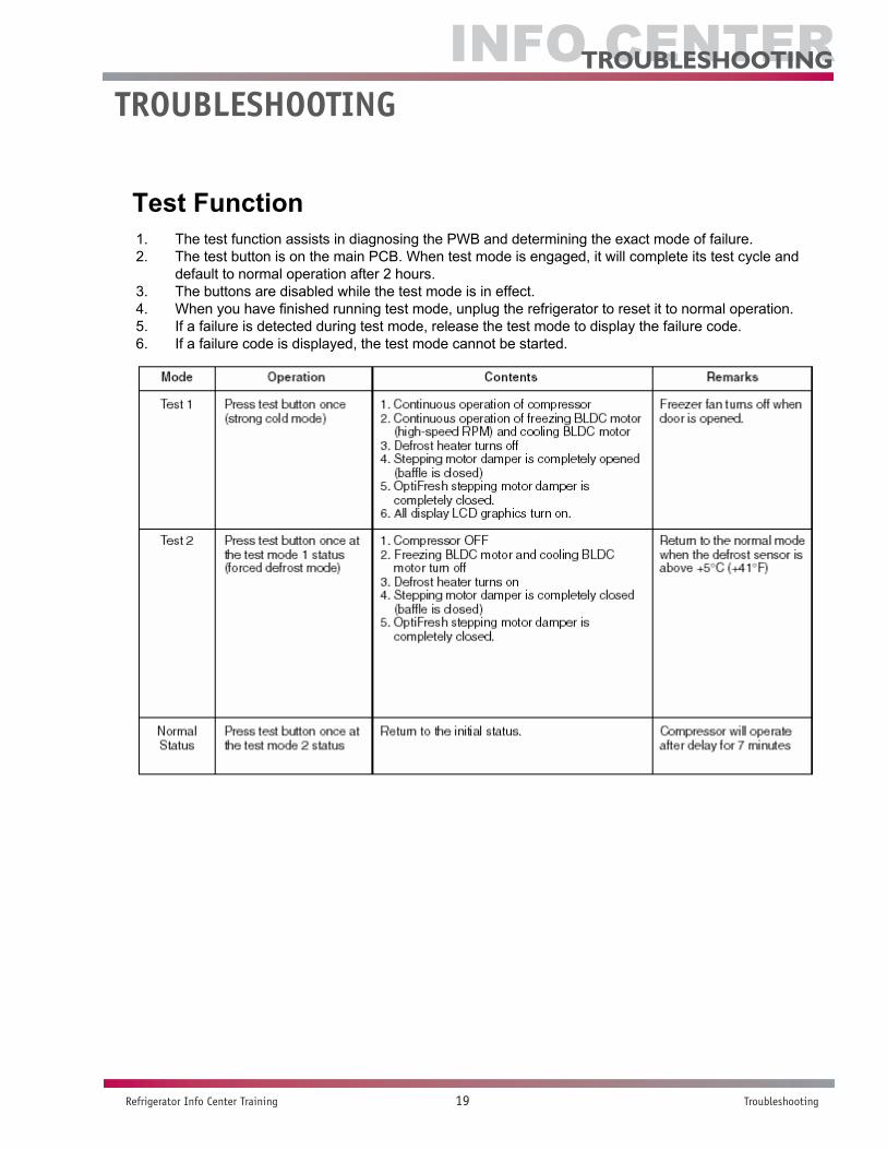
1. The test function assists in diagnosing the PWB and determining the exact mode of failure.2. The test button is on the main PCB. When test mode is engaged, it will complete its test cycle and
default to normal operation after 2 hours.3. The buttons are disabled while the test mode is in effect.4. When you have finished running test mode, unplug the refrigerator to reset it to normal operation.5. If a failure is detected during test mode, release the test mode to display the failure code.6. If a failure code is displayed, the test mode cannot be started.
Test Function
TROublEShOOTING

Info Center
Refrigerator Info Center Training 20 Troubleshooting
TroUblesHooTinG
Failure Diagnosis FunctionFailure diagnosis facilitates service when a failure code shows during product operation. When a failure is detected, the buttons are deactivated. If a failure code is released, the MICOM resets and normal operation continues. The failure code is displayed on the display screen. All display graphics that are not part of the failure code are turned off.
All display parts turn off other than the freezer room and refrigerator temperature display (Failure code indicator). Refer to Notes 1, 2 for error display differences.
NOTE 1: If there is an error code displayed it will only be seen in the ambient temperature display area. This will still scroll between the ambient and outside temperature.
NOTE 2: It is possible for the R2-Sensor, water tank and optichill sensor not to display an error except while the unit is in the test mode.
Accessing the test mode1. Press and hold the lock button down for three seconds. 2. Press the sound and temperature buttons simultaneously for 1 second.
NO ITEMFAILURE CODE INDICATION
Contents of FailurePRODUCT OPERATION STATUS IN FAILURE
Freezer room notch Referidgerator room notch Compressor Freezer BLDC Cooling Defrost Stepping motor
1 Abnormal frerezer sensor Er Fs Freezer sensor shortOn for 15 minuets and off for 15 minuets
Standard RPM O O O
2Abnormal referidgerator sensor (R1) (Upper area in referidgerator)
Er rS Referidgerator sensor (R1) short O Standard RPM O O
Full opening for 10 minuets. Full closing for
15 minuets
3Abnormal referidgerator sensor (R2) (Lower area in referidgerator)
Normal display (Note 2) Referidgerator sensor (R2) short O Standard RPM O O O
4 Abnormal defrost sensor Er dS Abnormal short circuit O Standard RPM O No defrost O5 Failed defrosting Er dH Defrost circuit open O Standard RPM O O O6 Abnormal freezing BLDC
motor Er FF Open or short circuit or motor defect in BLDC circuit.
O Off O O O
7 Abnormal cooling BLDC motor Er CF O Standard RPM O O O
8 Abnormal communication Er COShorted or open lead wire between main and display PCB.
O Standard RPM O O O
9 Abnormal ambient sensor Normal display (Note 1) Ambient sensor short circuit O O O O O
10 Abnormal water tank sensor Normal display (Note 2) Water tank sensor short circuit O O O O O
11 Abnormal optichill sensor Normal display (Note 2) Optichill sensor short circuit O O O O O
R2 sensor (middle room)Normal Date and clock area of the display is on.
Other areas of the display are on
Abnormal Date and clock area of the display is off.
Water tank sensorNormal The dispenser state area of the display is on.Abnormal The dispenser state area of the display is off.
Optifresh sensorNormal Ambient temperature area of the display is onAbnormal Ambient temperature area of the display is off
Main PCB test key operationMODE OPERATION CONTENTS REMARKS
TEST 1 Press the test button once (Strong cold mode)
1. Continuous operation of the compressor. 2. Continuous operation of freezing and cooling BLDC motor (High speed RPM). 3. Defrost heater turns off. 4. Main stepping motor is completely open. 5. All display graphics turn on.
Freezing fan turns off when the door is opened.
TEST 2 Press the test button once wile in test mode 1 (Forced defrost mode)
1. Compressor off. 2. Freezing and cooling BLDC motor turn off. 3. Defrost heater turns on. 4. Main stepping motor is completely closed. 5. All display graphics turn off (Only the failure area turns on).
Returns to normal mode when the defrost sensor is above +5 degrees C
NORMAL STATUS
Press the test button once while in test mode 2 Returning to normal status Compressor will operate after a
seven minute delay.
Info Center
Refrigerator Info Center Training 21 Circuit Descriptions
CirCUiT DesCripTions
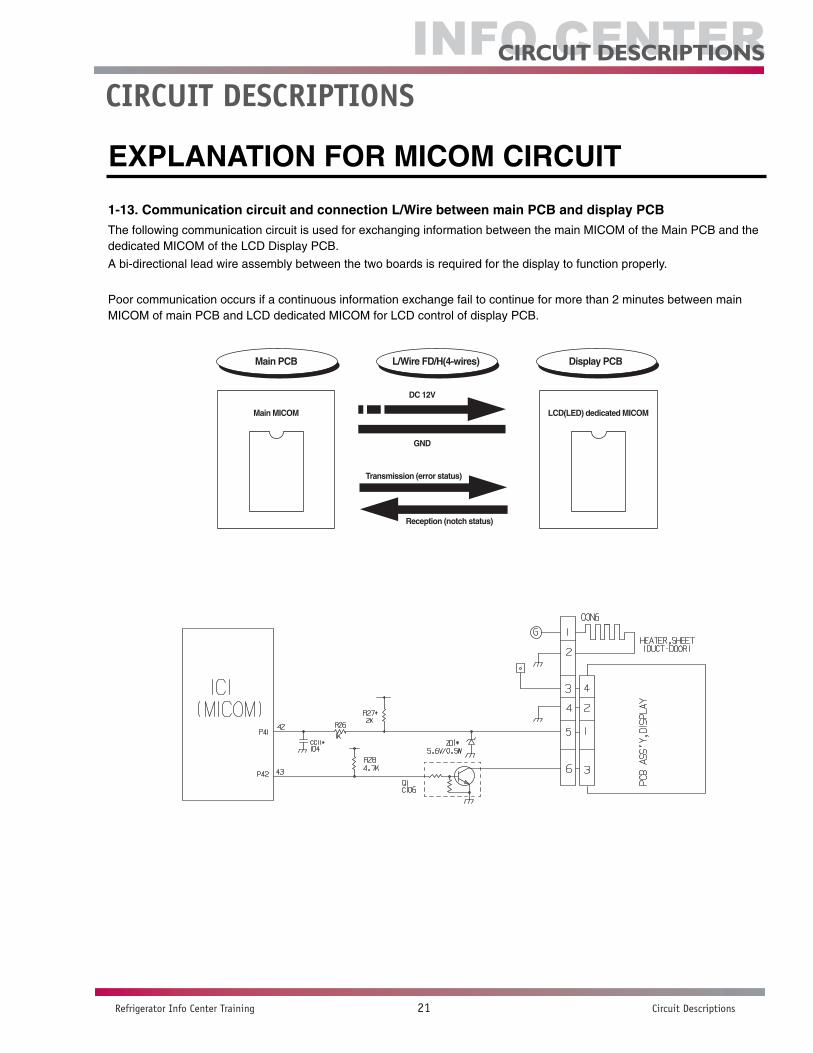
1-13. Communication circuit and connection L/Wire between main PCB and display PCBThe following communication circuit is used for exchanging information between the main MICOM of the Main PCB and thededicated MICOM of the LCD Display PCB.
A bi-directional lead wire assembly between the two boards is required for the display to function properly.
Poor communication occurs if a continuous information exchange fail to continue for more than 2 minutes between mainMICOM of main PCB and LCD dedicated MICOM for LCD control of display PCB.
EXPLANATION FOR MICOM CIRCUIT
- 34 -
Main MICOM LCD(LED) dedicated MICOM
DC 12V
GND
Transmission (error status)
Reception (notch status)
Main PCB L/Wire FD/H(4-wires) Display PCB
CIRCuIT dESCRIPTIONS

Info Center
Refrigerator Info Center Training 22 Circuit Descriptions
CirCUiT DesCripTions
2) Sensor resistance characteristics table
u Resistance value allowance of sensor is ±5%. u When measuring the resistance value of the sensor, allow the temperature of that sensor to stabilize for at least 3 minutes
before measuring. This delay is necessary because of the sense speed relationship. u Use a digital tester to measure the resistance. An analog tester has to great a margin of error.u Resistance of the cold storage sensor 1 and 2 shall be measured with a digital tester after separating CON8 of the PWB
ASSEMBLY and the MAIN part. u Resistance of the freezing sensor shall be measured with a digital tester after separating CON7 of the PWB ASSEMBLY
and the MAIN part.
EXPLANATION FOR MICOM CIRCUIT
- 35 -
Measuring Temperature (°C) Freezing Sensor Refrigerator sensor 1&2
Defrost sensor, Ambient sensor
-20 °C 22.3 kΩ 77 kΩ
-15 °C 16.9 kΩ 60 kΩ
-15 °C 13.0 kΩ 47.3 kΩ
-5 °C 10.1 kΩ 38.4 kΩ
0 °C 7.8 kΩ 30 kΩ
+5 °C 6.2 kΩ 24.1 kΩ
+10 °C 4.9 kΩ 19.5 kΩ
+15 °C 3.9 kΩ 15.9 kΩ
+20 °C 3.1 kΩ 13 kΩ
+25 °C 2.5 kΩ 11 kΩ
+30 °C 2.0 kΩ 8.9 kΩ
+40 °C 1.4 kΩ 6.2 kΩ
+50 °C 0.8 kΩ 4.3 kΩ

Info Center
Refrigerator Info Center Training 23 Circuit Descriptions
CirCUiT DesCripTions
Explanation of PWB circuit
The power circuit includes a Switched Mode Power Supply (SMPS). It consists of a rectifier (BD1 and CE1) converting AC to DC, a switch (IC2) switching the DC voltage, a transformer, and a feedback circuit (IC3 and IC4).
Caution : Since high voltage (160 Vdc) is maintained at the power terminal, wait at least 3 minutes after unplugging the appliance to check the voltages to allow the current to dissipate.
VOLTAGE CHART
Power circuit1. Explanation for PWB circuit
1-1. Power circuitThe power circuit includes a Switched Mode Power Supply (SMPS). It consists of a rectifier (BD1 and CE1) converting ACto DC, a switch (IC2) switching the DC voltage, a transformer, and a feedback circuit (IC3 and IC4).
Caution : Since high voltage (160 Vdc) is maintained at the power terminal, wait at least 3 minutes after unplugging theappliance to check the voltages to allow the current to dissipate.
Voltage of every part is as follows:
EXPLANATION FOR MICOM CIRCUIT
- 22 -
Part VA1 CE1 CE2 CE3 CE4 CE5
Voltage 120 Vac 160 Vdc 14 Vdc 12 Vdc 15.5 Vdc 5 Vdc

Info Center
Refrigerator Info Center Training 24 Circuit Descriptions
CirCUiT DesCripTions
Oscillation circuit
Figure 1The oscillation circuit generates a basic clock signal for synchronization and time calculation related to the transmission of data and calculations made by the MICOM (IC1). The oscillator (OSC1) must always be replaced with an exact replacement part. If this specification is changed, the change will affect the time calculations of the MICOM and it might not work at all.
Fig 1 Fig 2
Reset circuit
Figure 2The RESET circuit allows various parts of the MICOM, such as RAM, defrosting, etc., to be restarted from the initial state when power is interrupted or restored. A LOW signal applied to the reset terminal for 10 ms causes the MICOM to reset itself. During normal operation, the voltage at the reset terminal is 5 Vdc. If the reset fails, the MICOM will not operate.
LOAD DRIVING CIRCUIT
•The fan operates at the regular speed even if the door of the refrigerator or freezer is opened. When thedoors are closed, the fan reverts to its original speed.
•(A), (B), (C), and (D) of door switch for the freezer or refrigerator are connected to the door open sensing circuit in parallel toward both ends of switch to determine door open at MICOM.
•In the TEST mode, the fan will stop if any door is opened. It will resume operation when the door is closed.
1-2. Oscillation circuitThe oscillation circuit generates a basic clock signal for synchronization and time calculation related to the transmission ofdata and calculations made by the MICOM (IC1). The oscillator (OSC1) must always be replaced with an exact replacementpart. If this specification is changed, the change will affect the time calculations of the MICOM and it might not work at all.
(1) GR-G277STSA(LSC27990TT)
1-3. Reset circuitThe RESET circuit allows various parts of the MICOM, such as RAM, defrosting, etc., to be restarted from the initial statewhen power is interrupted or restored. A LOW signal applied to the reset terminal for 10 ms causes the MICOM to resetitself. During normal operation, the voltage at the reset terminal is 5 Vdc. If the reset fails, the MICOM will not operate.
(1) GR-G277STSA(LSC27990TT)
EXPLANATION FOR MICOM CIRCUIT
- 23 -
1-4. Load/dispenser operation, door opening circuit
1. LOAD DRIVING CIRCUIT The fan operates at the regular speed even if the door of the refrigerator or freezer is opened. When the doors are closed,
the fan reverts to its original speed. (A), (B), (C), and (D) of door switch for the freezer or refrigerator are connected to the door open sensing circuit in parallel
toward both ends of switch to determine door open at MICOM. In the TEST mode, the fan will stop if any door is opened. It will resume operation when the door is closed.
(1) GR-G277STSA(LSC27990TT)
EXPLANATION FOR MICOM CIRCUIT
- 24 -
Measuring part (IC6) IC6-16 IC6-13 IC6-12 IC6-15 IC6-14
StatusON Within 1 V
OFF 12 V
Type of Load CompressorDefrost Heater
AC ConvertingRelay
RefrigeratorLAMP
DispenserHeater

Info Center
Refrigerator Info Center Training 25 Circuit Descriptions
CirCUiT DesCripTions
1-4. Load/dispenser operation, door opening circuit
1. LOAD DRIVING CIRCUIT The fan operates at the regular speed even if the door of the refrigerator or freezer is opened. When the doors are closed,
the fan reverts to its original speed. (A), (B), (C), and (D) of door switch for the freezer or refrigerator are connected to the door open sensing circuit in parallel
toward both ends of switch to determine door open at MICOM. In the TEST mode, the fan will stop if any door is opened. It will resume operation when the door is closed.
(1) GR-G277STSA(LSC27990TT)
EXPLANATION FOR MICOM CIRCUIT
- 24 -
Measuring part (IC6) IC6-16 IC6-13 IC6-12 IC6-15 IC6-14
StatusON Within 1 V
OFF 12 V
Type of Load CompressorDefrost Heater
AC ConvertingRelay
RefrigeratorLAMP
DispenserHeater
1-5. Dispenser operation circuit
(1) GR-G277STSA(LSC27990TT)
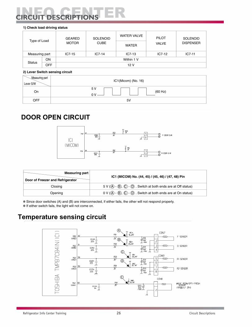
1) Check load driving status
2) Lever Switch sensing circuit
EXPLANATION FOR MICOM CIRCUIT
- 25 -
Measuring part
Lever S/WIC1(Micom) (No. 16)
On
OFF 5V
0 V(60 Hz)
5 V
Measuring part IC7-15 IC7-14 IC7-13 IC7-12 IC7-11
Status ON Within 1 V
OFF 12 V
Type of LoadGEAREDMOTOR
SOLENOIDCUBE
PILOT
VALVE
WATER VALVE
WATER
SOLENOIDDISPENSER
LOAD DRIVE SCHEMATIC
DISPENSER CIRCUIT
LOAD DRIVE SCHEMATIC
DISPENSER CIRCUIT
Info Center
Refrigerator Info Center Training 26 Circuit Descriptions
CirCUiT DesCripTions
1-5. Dispenser operation circuit
(1) GR-G277STSA(LSC27990TT)
1) Check load driving status
2) Lever Switch sensing circuit
EXPLANATION FOR MICOM CIRCUIT
- 25 -
Measuring part
Lever S/WIC1(Micom) (No. 16)
On
OFF 5V
0 V(60 Hz)
5 V
Measuring part IC7-15 IC7-14 IC7-13 IC7-12 IC7-11
Status ON Within 1 V
OFF 12 V
Type of LoadGEAREDMOTOR
SOLENOIDCUBE
PILOT
VALVE
WATER VALVE
WATER
SOLENOIDDISPENSER
LOAD DRIVE STATUS
LEVER SWITCH CIRCUIT
DOOR OPEN CIRCUIT
•Since door switches (A) and (B) are interconnected, if either fails, the other will not respond properly.•If either switch fails, the light will not come on.
Temperature sensing circuit
1-6. Door opening sensing circuit
Since door switches (A) and (B) are interconnected, if either fails, the other will not respond properly. If either switch fails, the light will not come on.
EXPLANATION FOR MICOM CIRCUIT
- 26 -
Closing 5 V ( A - B , C - D . Switch at both ends are at Off status)
Opening 0 V ( A - B , C - D . Switch at both ends are at On status)
Measuring partIC1 (MICOM) No. (44, 45) / (45, 46) / (47, 48) Pin
Door of Freezer and Refrigerator
LOAD DRIVE STATUS
LEVER SWITCH CIRCUIT
DOOR OPEN CIRCUIT
•Since door switches (A) and (B) are interconnected, if either fails, the other will not respond properly.•If either switch fails, the light will not come on.
Temperature sensing circuit1-7. Temperature sensing circuit
(1) GR-G277STSA(LSC27990TT)
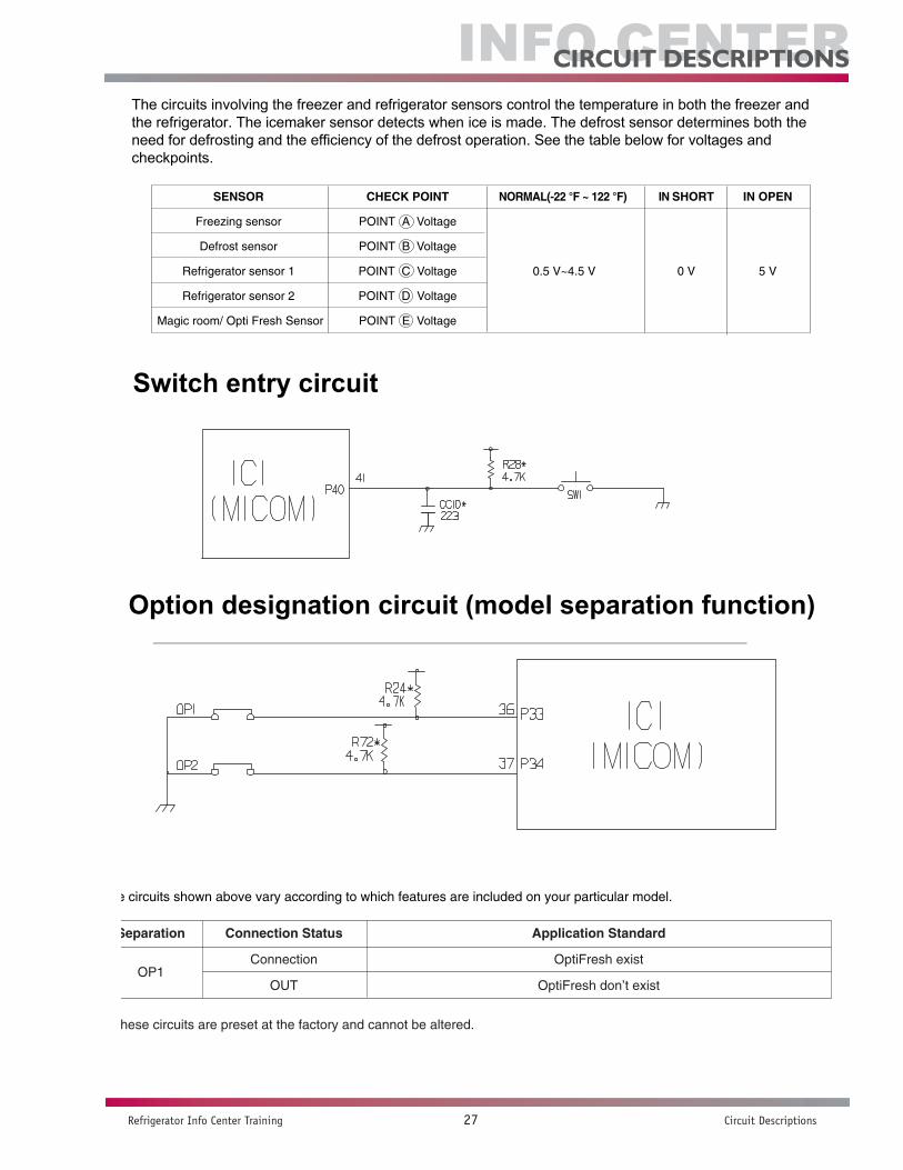
The circuits involving the freezer and refrigerator sensors control the temperature in both the freezer and the refrigerator.The icemaker sensor detects when ice is made. The defrost sensor determines both the need for defrosting and theefficiency of the defrost operation. See the table below for voltages and checkpoints.
EXPLANATION FOR MICOM CIRCUIT
- 27 -
SENSOR CHECK POINT NORMAL(-22 °F ~ 122 °F) IN SHORT IN OPEN
Freezing sensor POINT A Voltage
Defrost sensor POINT B Voltage
Refrigerator sensor 1 POINT C Voltage 0.5 V~4.5 V 0 V 5 V
Refrigerator sensor 2 POINT D Voltage
Magic room/ Opti Fresh Sensor POINT E Voltage
Info Center
Refrigerator Info Center Training 27 Circuit Descriptions
CirCUiT DesCripTions
The circuits involving the freezer and refrigerator sensors control the temperature in both the freezer and the refrigerator. The icemaker sensor detects when ice is made. The defrost sensor determines both the need for defrosting and the efficiency of the defrost operation. See the table below for voltages and checkpoints.
Switch entry circuit
The following circuits are sensing signal form the damper motor reed switch for testing and diagnosing the refrigerator.
Option designation circuit (model separation function)
The circuits shown above vary according to which features are included on your particular model.
1-8. Switch entry circuitThe following circuits are sensing signal form the damper motor reed switch for testing and diagnosing the refrigerator.
(1) GR-G277STSA(LSC27990TT)
1-9. Option designation circuit (model separation function)
(1) GR-G277STSA(LSC27990TT)
The circuits shown above vary according to which features are included on your particular model.
uThese circuits are preset at the factory and cannot be altered.
EXPLANATION FOR MICOM CIRCUIT
- 28 -
Separation Connection Status Application Standard
Connection OptiFresh existOP1
OUT OptiFresh don’t exist
The circuits involving the freezer and refrigerator sensors control the temperature in both the freezer and the refrigerator. The icemaker sensor detects when ice is made. The defrost sensor determines both the need for defrosting and the efficiency of the defrost operation. See the table below for voltages and checkpoints.
Switch entry circuit
The following circuits are sensing signal form the damper motor reed switch for testing and diagnosing the refrigerator.
Option designation circuit (model separation function)
The circuits shown above vary according to which features are included on your particular model.
1-7. Temperature sensing circuit
(1) GR-G277STSA(LSC27990TT)
The circuits involving the freezer and refrigerator sensors control the temperature in both the freezer and the refrigerator.The icemaker sensor detects when ice is made. The defrost sensor determines both the need for defrosting and theefficiency of the defrost operation. See the table below for voltages and checkpoints.
EXPLANATION FOR MICOM CIRCUIT
- 27 -
SENSOR CHECK POINT NORMAL(-22 °F ~ 122 °F) IN SHORT IN OPEN
Freezing sensor POINT A Voltage
Defrost sensor POINT B Voltage
Refrigerator sensor 1 POINT C Voltage 0.5 V~4.5 V 0 V 5 V
Refrigerator sensor 2 POINT D Voltage
Magic room/ Opti Fresh Sensor POINT E Voltage
Info Center
Refrigerator Info Center Training 28 Circuit Descriptions
CirCUiT DesCripTions
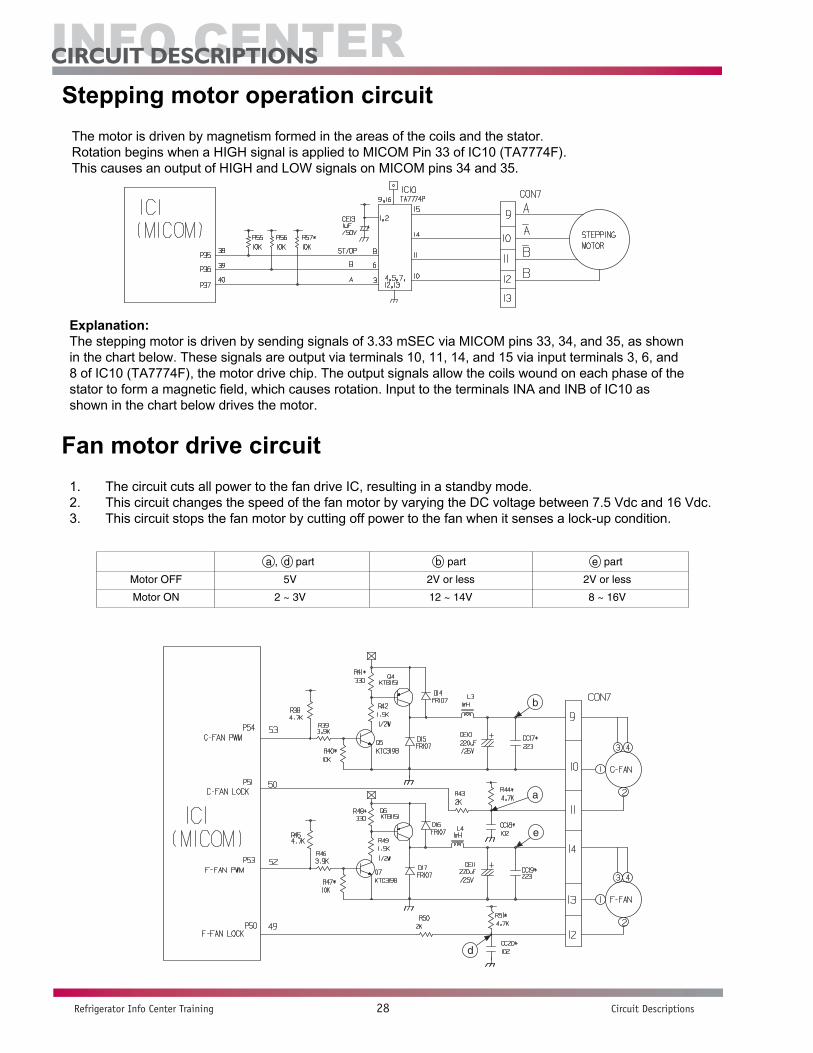
Stepping motor operation circuitThe motor is driven by magnetism formed in the areas of the coils and the stator. Rotation begins when a HIGH signal is applied to MICOM Pin 33 of IC10 (TA7774F). This causes an output of HIGH and LOW signals on MICOM pins 34 and 35.
Explanation:The stepping motor is driven by sending signals of 3.33 mSEC via MICOM pins 33, 34, and 35, as shown in the chart below. These signals are output via terminals 10, 11, 14, and 15 via input terminals 3, 6, and 8 of IC10 (TA7774F), the motor drive chip. The output signals allow the coils wound on each phase of the stator to form a magnetic field, which causes rotation. Input to the terminals INA and INB of IC10 as shown in the chart below drives the motor.
Fan motor drive circuit1. The circuit cuts all power to the fan drive IC, resulting in a standby mode.2. This circuit changes the speed of the fan motor by varying the DC voltage between 7.5 Vdc and 16 Vdc.3. This circuit stops the fan motor by cutting off power to the fan when it senses a lock-up condition.
1-10. Stepping motor operation circuit
(1) GR-G277STSA(LSC27990TT)The motor is driven by magnetism formed in the areas of the coils and the stator. Rotation begins when a HIGH signal is
applied to MICOM Pin 33 of IC10 (TA7774F). This causes an output of HIGH and LOW signals on MICOM pins 34 and 35.
Explanation) The stepping motor is driven by sending signals of 3.33 mSEC via MICOM pins 33, 34, and 35, as shown inthe chart below. These signals are output via terminals 10, 11, 14, and 15 via input terminals 3, 6, and 8 ofIC10 (TA7774F), the motor drive chip. The output signals allow the coils wound on each phase of the stator toform a magnetic field, which causes rotation. Input to the terminals INA and INB of IC10 as shown in the chartbelow drives the motor.
EXPLANATION FOR MICOM CIRCUIT
- 29 -
INA
INB
A
B
A
B
CCW (Reverse rotation) (Positive rotation) CW
Stepping motor operation circuitThe motor is driven by magnetism formed in the areas of the coils and the stator. Rotation begins when a HIGH signal is applied to MICOM Pin 33 of IC10 (TA7774F). This causes an output of HIGH and LOW signals on MICOM pins 34 and 35.
Explanation:The stepping motor is driven by sending signals of 3.33 mSEC via MICOM pins 33, 34, and 35, as shown in the chart below. These signals are output via terminals 10, 11, 14, and 15 via input terminals 3, 6, and 8 of IC10 (TA7774F), the motor drive chip. The output signals allow the coils wound on each phase of the stator to form a magnetic field, which causes rotation. Input to the terminals INA and INB of IC10 as shown in the chart below drives the motor.
Fan motor drive circuit1. The circuit cuts all power to the fan drive IC, resulting in a standby mode.2. This circuit changes the speed of the fan motor by varying the DC voltage between 7.5 Vdc and 16 Vdc.3. This circuit stops the fan motor by cutting off power to the fan when it senses a lock-up condition.
1-11. Fan motor driving circuit (freezer, mechanical area)1. The circuit cuts all power to the fan drive IC, resulting in a standby mode.
2. This circuit changes the speed of the fan motor by varying the DC voltage between 7.5 Vdc and 16 Vdc.
3. This circuit stops the fan motor by cutting off power to the fan when it senses a lock-up condition.
(1) GR-G277STSA(LSC27990TT)
EXPLANATION FOR MICOM CIRCUIT
- 30 -
a , d part b part e part
Motor OFF 5V 2V or less 2V or less
Motor ON 2 ~ 3V 12 ~ 14V 8 ~ 16V
b
a
d
e
Info Center
Refrigerator Info Center Training 29 Circuit Descriptions
CirCUiT DesCripTions
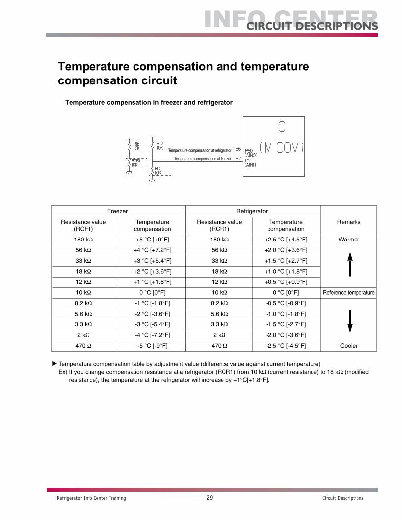
Temperature compensation and temperature compensation circuit
Temperature compensation in freezer and refrigerator
NOTE Temperature compensation table by adjustment value (difference value against current temperature)Ex) If you change compensation resistance at a refrigerator (RCR1) from 10 k (current resistance) to 18 k (modified resistance), the temperature at the refrigerator will increase by +1°C[+1.8°F].
EXPLANATION FOR MICOM CIRCUIT
- 31 -
Temperature compensation at refrigerator
Temperature compensation at freezer
1-12. Temperature compensation and temperature compensation circuit1. Temperature compensation in freezer and refrigerator
(1) GR-G277STSA(LSC27990TT)
u Temperature compensation table by adjustment value (difference value against current temperature) Ex) If you change compensation resistance at a refrigerator (RCR1) from 10 kΩ (current resistance) to 18 kΩ (modified
resistance), the temperature at the refrigerator will increase by +1°C[+1.8°F].
Temperature compensation at refrigerator
Temperature compensation at freezer
Freezer Refrigerator
Resistance value Temperature Resistance value Temperature Remarks(RCF1) compensation (RCR1) compensation
180 kΩ +5 °C [+9°F] 180 kΩ +2.5 °C [+4.5°F] Warmer
56 kΩ +4 °C [+7.2°F] 56 kΩ +2.0 °C [+3.6°F]
33 kΩ +3 °C [+5.4°F] 33 kΩ +1.5 °C [+2.7°F]
18 kΩ +2 °C [+3.6°F] 18 kΩ +1.0 °C [+1.8°F]
12 kΩ +1 °C [+1.8°F] 12 kΩ +0.5 °C [+0.9°F]
10 kΩ 0 °C [0°F] 10 kΩ 0 °C [0°F] Reference temperature
8.2 kΩ -1 °C [-1.8°F] 8.2 kΩ -0.5 °C [-0.9°F]
5.6 kΩ -2 °C [-3.6°F] 5.6 kΩ -1.0 °C [-1.8°F]
3.3 kΩ -3 °C [-5.4°F] 3.3 kΩ -1.5 °C [-2.7°F]
2 kΩ -4 °C [-7.2°F] 2 kΩ -2.0 °C [-3.6°F]
470 Ω -5 °C [-9°F] 470 Ω -2.5 °C [-4.5°F] Cooler

Info Center
Refrigerator Info Center Training 30 Circuit Descriptions
CirCUiT DesCripTions
Temperature compensation table at the refrigerator is as follows:
•Temperature compensation at the freezer is performed the same as at the refrigerator. The value forthe freezer is twice that of the refrigerator.
•This circuit enters the necessary level of temperature compensation for adjusting the appliance. The method is the same for every model in this appliance family.
u Temperature compensation table at the refrigerator is as follows:
u Temperature compensation at the freezer is performed the same as at the refrigerator. The value for the freezer is twicethat of the refrigerator.
u This circuit enters the necessary level of temperature compensation for adjusting the appliance. The method is the samefor every model in this appliance family.
EXPLANATION FOR MICOM CIRCUIT
- 32 -
470 Ω 2 kΩ 3.3 kΩ 5.6 kΩ 8.2 kΩ 10 kΩ 12 kΩ 18 kΩ 33 kΩ 56 kΩ 180 kΩ
No 0.5 °C 1 °C 1.5 °C 2 °C 2.5 °C 3 °C 3.5 °C 4 °C 4.5 °C 5 °C470Ω [0.9 °F] [1.8 °F] [2.7 °F] [3.6 °F] [4.5 °F] [5.4 °F] [6.3 °F] [7.2 °F] [8.1 °F] [9 °F]
change Up Up Up Up Up Up Up Up Up Up
0.5 °C No 0.5 °C 1 °C 1.5 °C 2 °C 2.5 °C 3 °C 3.5 °C 4 °C 4.5 °C2 kΩ [0.9 °F] [0.9 °F] [1.8 °F] [2.7 °F] [3.6 °F] [4.5 °F] [5.4 °F] [6.3 °F] [7.2 °F] [8.1 °F]
Down change Up Up Up Up Up Up Up Up Up
1 °C 0.5 °C No 0.5 °C 1 °C 1.5 °C 2 °C 2.5 °C 3 °C 3.5 °C 4 °C3.3 kΩ [1.8 °F] [0.9 °F] [0.9 °F] [1.8 °F] [2.7 °F] [3.6 °F] [4.5 °F] [5.4 °F] [6.3 °F] [7.2 °F]
Down Down change Up Up Up Up Up Up Up Up
1.5 °C 1 °C 0.5 °C No 0.5 °C 1 °C 1.5 °C 2 °C 2.5 °C 3 °C 3.5 °C5.6 kΩ [2.7 °F] [1.8 °F] [0.9 °F] [0.9 °F] [1.8 °F] [2.7 °F] [3.6 °F] [4.5 °F] [5.4 °F] [6.3 °F]
Down Down Down change Up Up Up Up Up Up Up
2 °C 1.5 °C 1 °C 0.5 ° No 0.5 °C 1 °C 1.5 °C 2 °C 2.5 °C 3 °C8.2 kΩ [3.6 °F] [2.7 °F] [1.8 °F] [0.9 °F] [0.9 °F] [1.8 °F] [2.7 °F] [3.6 °F] [4.5 °F] [5.4 °F]
Refrigerator Down Down Down Drop change Up Up Up Up Up Up
(RCR1) 2.5 °C 2 °C 1.5 °C 1 °C 0.5 °C No 0.5 °C 1 °C 1.5 °C 2 °C 2.5 °C10 kΩ [4.5 °F] [3.6 °F] [2.7 °F] [1.8 °F] [0.9 °F] [0.9 °F] [1.8 °F] [2.7 °F] [3.6 °F] [4.5 °F]
Down Down Down Down Down change Up Up Up Up Up
3 °C 2.5 °C 2 °C 1.5 °C 1 °C 0.5 °C No 0.5 °C 1 °C 1.5 °C 2 °C12 kΩ [5.4 °F] [4.5 °F] [3.6 °F] [2.7 °F] [1.8 °F] [0.9 °F] [0.9 °F] [1.8 °F] [2.7 °F] [3.6 °F]
Down Down Down Down Down Down change Up Up Up Up
3.5 °C 3 °C 2.5 °C 2 °C 1.5 °C 1 °C 0.5 °C No 0.5 °C 1 °C 1.5 °C18 kΩ [6.3 °F] [5.4 °F] [4.5 °F] [3.6 °F] [2.7 °F] [1.8 °F] [0.9 °F] [0.9 °F] [1.8 °F] [2.7 °F]
Down Down Down Down Down Down Down change Up Up Up
4 °C 3.5 °C 3 °C 2.5 °C 2 °C 1.5 °C 1 °C 0.5 °C No 0.5 °C 1 °C33 kΩ [7.2 °F] [6.3 °F] [5.4 °F] [4.5 °F] [3.6 °F] [2.7 °F] [1.8 °F] [0.9 °F] [0.9 °F] [1.8 °F]
Down Down Down Down Down Down Down Down change Up Up
4.5 °C 4 °C 3.5 °C 3 °C 2.5 °C 2 °C 1.5 °C 1 °C 0.5 °C No 0.5 °C56 kΩ [8.1 °F] [7.2 °F] [6.3 °F] [5.4 °F] [4.5 °F] [3.6 °F] [2.7 °F] [1.8 °F] [0.9 °F] [0.9 °F]
Down Down Down Down Down Down Down Down Down change Up
5 °C 4.5 °C 4 °C 3.5 °C 3 °C 2.5 °C 2 °C 1.5 °C 1 °C 0.5 °C No180 kΩ [9 °F] [8.1 °F] [7.2 °F] [6.3 °F] [5.4 °F] [4.5 °F] [3.6 °F] [2.7 °F] [1.8 °F] [0.9 °F]
Down Down Down Down Down Down Down Down Down Down change
Modificationresistance
Currentresistance

Info Center
Refrigerator Info Center Training 31 Circuit Descriptions
CirCUiT DesCripTions
Compensation circuit for temperature at freezer
This circuit allows adjustment of the set temperature for compensation by changing jumpers at locations JCR1~JCR4.
2. Compensation circuit for temperature at freezer
(1) GR-G277STSA(LSC27990TT)
u This circuit allows adjustment of the set temperature for compensation by changing jumpers at locations JCR1~JCR4.
EXPLANATION FOR MICOM CIRCUIT
- 33 -
Compensation Compensation for too warm for too cold Temperature compensation value Remarks
JCR3 JCR4 JCR1 JCR2at refrigerator
0 °C (In shipment from factory)
CUT -1 °C [-1.8 °F]
CUT -1 °C [-1.8 °F]
CUT +1 °C [+1.8 °F]
CUT +1 °C [+1.8 °F]
CUT CUT -2 °C [-3.6 °F]
CUT CUT +2 °C [+3.6 °F]
CUT CUT 0 °C [0 °F]
CUT CUT 0 °C [0 °F]
CUT CUT 0 °C [0 °F]
CUT CUT 0 °C [0 °F]
CUT CUT CUT -1 °C [-1.8 °F]
CUT CUT CUT +1 °C [+1.8 °F]
CUT CUT CUT CUT 0 °C [0 °F]
Temperature compensation in CUT
JCR1 +1 °C [+1.8 °F]+2 °C [+3.6 °F]
JCR2 +1 °C [+1.8 °F]
JCR3 -1 °C [-1.8 °F]-2 °C [-3.6 °F]
JCR4 -1 °C [-1.8 °F]


2007 Info Center Refrigerator Training