lg lcd projectorlg lcd projector
TRANSCRIPT
R
RL-JT10OWNER’S MANUALLG
LCD
PR
OJE
CTO
RLG
LC
D
PRO
JEC
TOR
Please read this manual carefully before operatingyour set. Retain it for future reference.Record model number and serial number of the set. See the label attached on the bottom of the set andquote this information to your dealer when yourequire service.
Model number :Serial number :
LCDPROJECTORLCDPROJECTOR
R
1
FCC NOTICE
• A Class A digital deviceThis equipment has been tested and found to comply with the limits for a Class A digitaldevice, pursuant to Part 15 of the FCC Rules. These limits are designed to provide rea-sonable protection against harmful interference when the equipment is operated in acommercial environment. This equipment generates, uses, and can radiate radio fre-quency energy and, if not installed and used in accordance with the instruction manual,may cause harmful interference to radio communications. Operation of this equipment ina residential area is likely to cause harmful interference in which case the user will berequired to correct the interference at his own expense.
ENG
LISH
CONTENTS
INDEX
Safety Instructions 3Names of parts 11
Installation Instructions 19
Composition 21
Turning on the Projector 23
Turning off the Projector 24
Operating the Projector 25
Selecting source mode 26
Function checking 34
Using Still function 35
Connecting to a Desktop PC 27Connecting to a Notebook PC 28Connecting to a Macintosh Desktop PC 29Connecting to a Macintosh PowerBook 30Connecting to a Video Source 31Connecting to a DVD 32Connecting to a D-TV Settop Box 33
Selecting language 36
Using Blank function 37
Using Flip Horizontal / Vertical function 39
Checking lamp time 41
Using Tracking function 45
Using Resize function 42
Adjusting screen display 43
Adjusting Video 47
External control device setup 48
2
Supported Monitor Display 58
Maintenance 59
Memo 60
Specifications 62
Before operating theunit, please read thismanual carefully.
INTRODUCTION
INSTALLATION ANDCOMPOSITION
CONNECTION
SPECIALFUNCTIONS
BASIC FUN-CTIONS
POSITIONING
TRACKING
VIDEO
RS-232C
INFORMATION
3
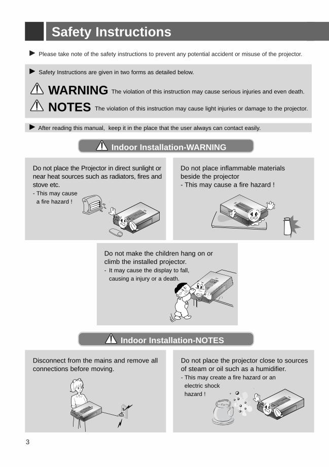
Safety InstructionsG Please take note of the safety instructions to prevent any potential accident or misuse of the projector.
G After reading this manual, keep it in the place that the user always can contact easily.
G Safety Instructions are given in two forms as detailed below.
WARNING The violation of this instruction may cause serious injuries and even death.
NOTES The violation of this instruction may cause light injuries or damage to the projector.
Indoor Installation-WARNING
Indoor Installation-NOTES
R
MENU
SOURCE
ENTER
PATTERN
POWER
VOL
VOL
R
R
Do not place the Projector in direct sunlight ornear heat sources such as radiators, fires andstove etc.- This may cause
a fire hazard !
Disconnect from the mains and remove allconnections before moving.
Do not place the projector close to sourcesof steam or oil such as a humidifier.- This may create a fire hazard or an
electric shock hazard !
R
MENU
SOURCE
ENTER
PATTERN
POWER
VOL
VOL
Do not place inflammable materialsbeside the projector - This may cause a fire hazard !
R
MENU
SOURCE
ENTER
PATTERN
POWER
VOL
VOL
Do not make the children hang on orclimb the installed projector. - It may cause the display to fall,
causing a injury or a death.
ENG
LISH
4
Indoor Installation-NOTES
R
MENU
SOURCE
ENTER
PATTERN
POWER
VOL
VOL
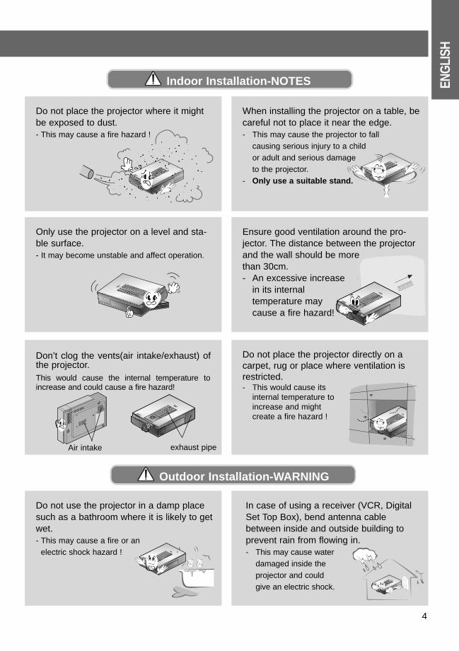
Do not place the projector where it mightbe exposed to dust.- This may cause a fire hazard !
R
When installing the projector on a table, becareful not to place it near the edge. - This may cause the projector to fall
causing serious injury to a child or adult and serious damage to the projector.
- Only use a suitable stand.
R
MENU
SOURCE
ENTER
PATTERN
POWER
VOL
VOL
Only use the projector on a level and sta-ble surface. - It may become unstable and affect operation.
R
Ensure good ventilation around the pro-jector. The distance between the projectorand the wall should be more than 30cm.- An excessive increase
in its internal temperature may cause a fire hazard!
R
Don’t clog the vents(air intake/exhaust) ofthe projector.This would cause the internal temperature toincrease and could cause a fire hazard!
R
MENU
SOURCE
ENTER
PATTERN
POWER
VOL
VOL
Do not place the projector directly on acarpet, rug or place where ventilation isrestricted.- This would cause its
internal temperature to increase and might create a fire hazard !
Air intake exhaust pipe
R
Do not use the projector in a damp placesuch as a bathroom where it is likely to getwet.- This may cause a fire or an
electric shock hazard !
R
In case of using a receiver (VCR, DigitalSet Top Box), bend antenna cablebetween inside and outside building toprevent rain from flowing in.- This may cause water
damaged inside the projector and could give an electric shock.
Outdoor Installation-WARNING
5
Safety Instructions
R
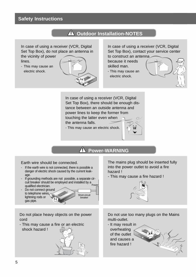
In case of using a receiver (VCR, DigitalSet Top Box), do not place an antenna inthe vicinity of power lines. - This may cause an
electric shock.
In case of using a receiver (VCR, DigitalSet Top Box), contact your service centerto construct an antenna because it needs skilled man.- This may cause an
electric shock.
In case of using a receiver (VCR, DigitalSet Top Box), there should be enough dis-tance between an outside antenna andpower lines to keep the former fromtouching the latter even when the antenna falls. - This may cause an electric shock.
R
MENU
SOURCE
ENTER
PATTERN
POWER
VOL
VOL
Earth wire should be connected.- If the earth wire is not connected, there is possible a
danger of electric shock caused by the current leak-age.
- If grounding methods are not possible, a separate cir-cuit breaker should be employed and installed by aqualified electrician.
- Do not connect ground to telephone wires,lightning rods or gas pipe.
The mains plug should be inserted fullyinto the power outlet to avoid a fire hazard !- This may cause a fire hazard !
Do not place heavy objects on the powercord - This may cause a fire or an electric
shock hazard !
R
Do not use too many plugs on the Mainsmulti-outlet.- It may result in
overheating of the outlet and causes afire hazard !
Outdoor Installation-NOTES
Power-WARNING
Short-circuit breaker
Power
ENG
LISH
6
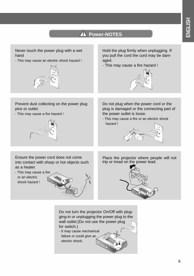
Never touch the power plug with a wethand- This may cause an electric shock hazard !
Hold the plug firmly when unplugging. Ifyou pull the cord the cord may be dam-aged.- This may cause a fire hazard !
Do not plug when the power cord or theplug is damaged or the connecting part ofthe power outlet is loose.- This may cause a fire or an electric shock
hazard !
Prevent dust collecting on the power plugpins or outlet.- This may cause a fire hazard !
R
MENU
SOURCE
ENTER
PATTERN
POWER
VOL
VOL
Place the projector where people will nottrip or tread on the power lead.
R
Do not turn the projector On/Off with plug-ging-in or unplugging the power plug to thewall outlet.(Do not use the power plug for switch.)- It may cause mechanical
failure or could give an electric shock.
R
MENU
SOURCE
ENTER
PATTERN
POWER
VOL
VOL
Ensure the power cord does not comeinto contact with sharp or hot objects suchas a heater.- This may cause a fire
or an electric shock hazard !
Power-NOTES
7
Safety Instructions
R
MENU
SOURCE
ENTER
PATTERN
POWER
VOL
VOL
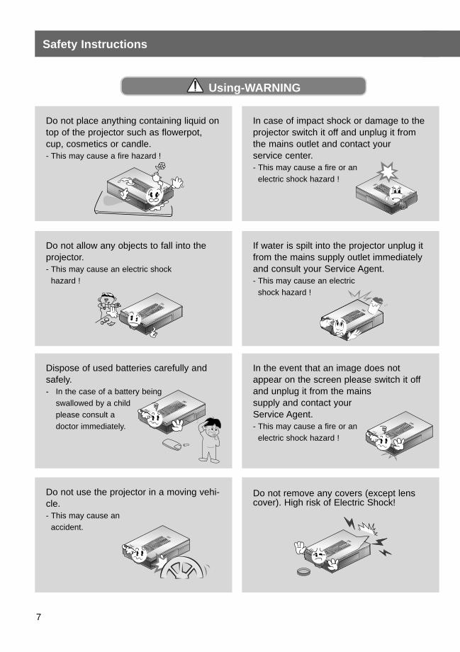
Do not place anything containing liquid ontop of the projector such as flowerpot, cup, cosmetics or candle.- This may cause a fire hazard !
R
In case of impact shock or damage to theprojector switch it off and unplug it fromthe mains outlet and contact your service center.- This may cause a fire or an
electric shock hazard !
R
MENU
SOURCE
ENTER
PATTERN
POWER
VOL
VOL
Do not allow any objects to fall into theprojector.- This may cause an electric shock
hazard !
R
If water is spilt into the projector unplug itfrom the mains supply outlet immediatelyand consult your Service Agent. - This may cause an electric
shock hazard !
R
MENU
SOURCE
ENTER
PATTERN
POWER
VOL
VOL
Dispose of used batteries carefully andsafely.- In the case of a battery being
swallowed by a child please consult a doctor immediately.
R
MENU
SOURCE
ENTER
PATTERN
POWER
VOL
VOL
In the event that an image does notappear on the screen please switch it offand unplug it from the mains supply and contact your Service Agent.- This may cause a fire or an
electric shock hazard !
R
MENU
SOURCE
ENTER
PATTERN
POWER
VOL
VOL
Do not use the projector in a moving vehi-cle. - This may cause an
accident.
R
MENU
SOURCE
ENTER
PATTERN
POWER
VOL
VOL
Do not remove any covers (except lenscover). High risk of Electric Shock!
Using-WARNING
ENG
LISH
8
Using-WARNING
Using-NOTES
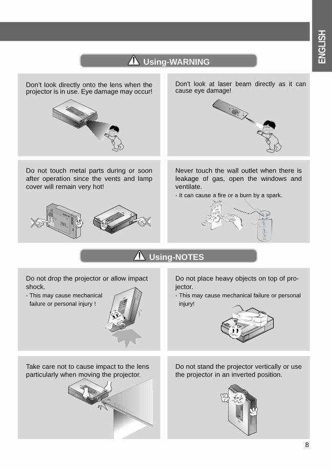
Don’t look at laser beam directly as it cancause eye damage!
R
Do not touch metal parts during or soonafter operation since the vents and lampcover will remain very hot!
Never touch the wall outlet when there isleakage of gas, open the windows andventilate.- It can cause a fire or a burn by a spark.
R
MENU
SOURCE
ENTER
PATTERN
POWER
VOL
VOL
Do not drop the projector or allow impactshock.- This may cause mechanical
failure or personal injury !
R
MENU
SOURCE
ENTER
PATTERN
POWER
VOL
VOL
Do not place heavy objects on top of pro-jector.- This may cause mechanical failure or personal
injury!
R
MENU
SOURCE
ENTER
PATTERN
POWER
VOL
VOL
Don’t look directly onto the lens when theprojector is in use. Eye damage may occur!
R
Take care not to cause impact to the lensparticularly when moving the projector.
R
Do not stand the projector vertically or usethe projector in an inverted position.
9
Safety Instructions
R
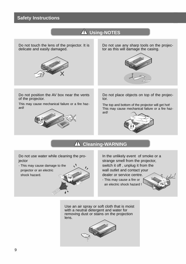
Do not use water while cleaning the pro-jector- This may cause damage to the
projector or an electric shock hazard.
R
MENU
SOURCE
ENTER
PATTERN
POWER
VOL
VOL
In the unlikely event of smoke or astrange smell from the projector, switch it off , unplug it from the wall outlet and contact your dealer or service centre.- This may cause a fire or
an electric shock hazard !
R
MENU
SOURCE
ENTER
PATTERN
POWER
VOL
VOL
Do not touch the lens of the projector. It isdelicate and easily damaged.
R
MENU
SOURCE
ENTER
PATTERN
POWER
VOL
VOL
Do not use any sharp tools on the projec-tor as this will damage the casing.
R
MENU
SOURCE
ENTER
PATTERN
POWER
VOL
VOL
Do not place objects on top of the projec-tor.
The top and bottom of the projector will get hot!This may cause mechanical failure or a fire haz-ard!
R
Do not position the AV box near the ventsof the projector.This may cause mechanical failure or a fire haz-ard!
Using-NOTES
Cleaning-WARNING
R
MENU
SOURCE
ENTER
PATTERN
POWER
VOL
VOL
Use an air spray or soft cloth that is moistwith a neutral detergent and water forremoving dust or stains on the projectionlens.
ENG
LISH
10
R
MENU
SOURCE
ENTER
PATTERN
POWER
VOL
VOL
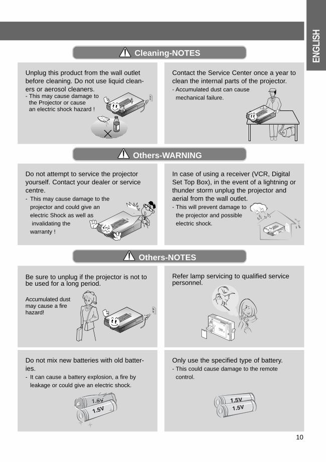
Unplug this product from the wall outletbefore cleaning. Do not use liquid clean-ers or aerosol cleaners.- This may cause damage to
the Projector or cause an electric shock hazard !
R
MENU
SOURCE
ENTER
PATTERN
POWER
VOL
VOL
Contact the Service Center once a year toclean the internal parts of the projector.- Accumulated dust can cause
mechanical failure.
R
MENU
SOURCE
ENTER
PATTERN
POWER
VOL
VOL
Do not attempt to service the projectoryourself. Contact your dealer or servicecentre.- This may cause damage to the
projector and could give an electric Shock as well asinvalidating the
warranty ! R
In case of using a receiver (VCR, DigitalSet Top Box), in the event of a lightning orthunder storm unplug the projector andaerial from the wall outlet. - This will prevent damage to
the projector and possible electric shock.
Only use the specified type of battery.- This could cause damage to the remote
control.
Do not mix new batteries with old batter-ies.- It can cause a battery explosion, a fire by
leakage or could give an electric shock.
Cleaning-NOTES
Others-WARNING
R
MENU
SOURCE
ENTER
PATTERN
POWER
VOL
VOL
Be sure to unplug if the projector is not tobe used for a long period.
Accumulated dust may cause a fire hazard!
Refer lamp servicing to qualified servicepersonnel.
Others-NOTES
11
Names of parts
R
MENU
SOURCE
ENTER
PATTERN
POWER
VOL
VOL
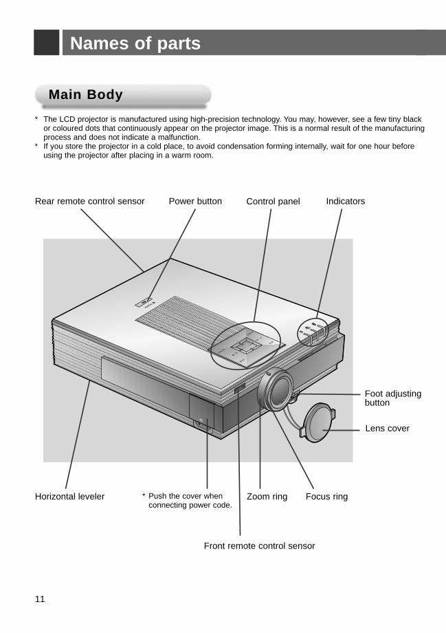
Main BodyMain Body
Rear remote control sensor
Foot adjustingbutton
Indicators
Front remote control sensor
Horizontal leveler * Push the cover when connecting power code.
Focus ring
Lens cover
Zoom ring
Power button Control panel
* The LCD projector is manufactured using high-precision technology. You may, however, see a few tiny black or coloured dots that continuously appear on the projector image. This is a normal result of the manufacturingprocess and does not indicate a malfunction.
* If you store the projector in a cold place, to avoid condensation forming internally, wait for one hour before using the projector after placing in a warm room.
ENG
LISH
12
R
K
AV Interface DVI Input
RS 232C
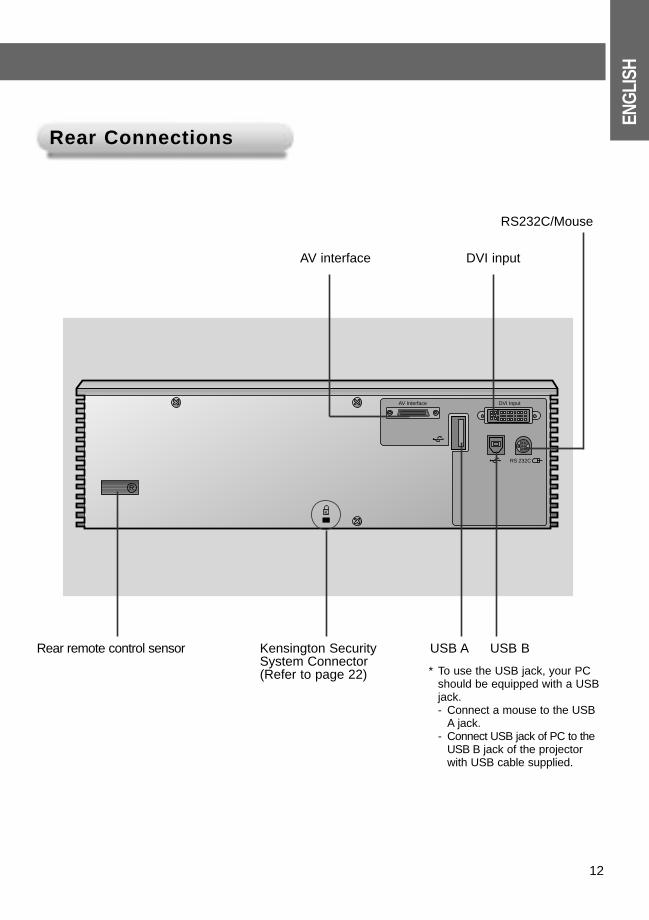
Rear ConnectionsRear Connections
USB A
AV interface DVI input
RS232C/Mouse
* To use the USB jack, your PC should be equipped with a USB jack.- Connect a mouse to the USB
A jack. - Connect USB jack of PC to the
USB B jack of the projector with USB cable supplied.
USB BKensington Security System Connector(Refer to page 22)
Rear remote control sensor
13
Names of parts
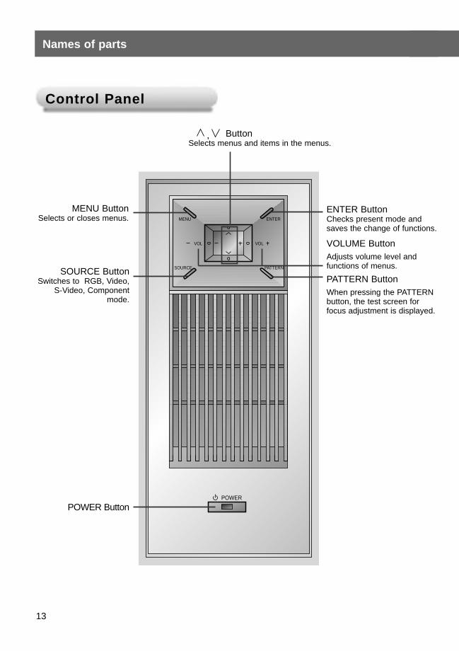
Control PanelControl Panel
MENU
SOURCE
ENTER
PATTERN
POWER
VOL VOL
POWER Button
, ButtonSelects menus and items in the menus.
MENU ButtonSelects or closes menus.
SOURCE ButtonSwitches to RGB, Video,
S-Video, Componentmode.
VOLUME ButtonAdjusts volume level and functions of menus.
ENTER ButtonChecks present mode and saves the change of functions.
PATTERN ButtonWhen pressing the PATTERNbutton, the test screen forfocus adjustment is displayed.
ENG
LISH
14
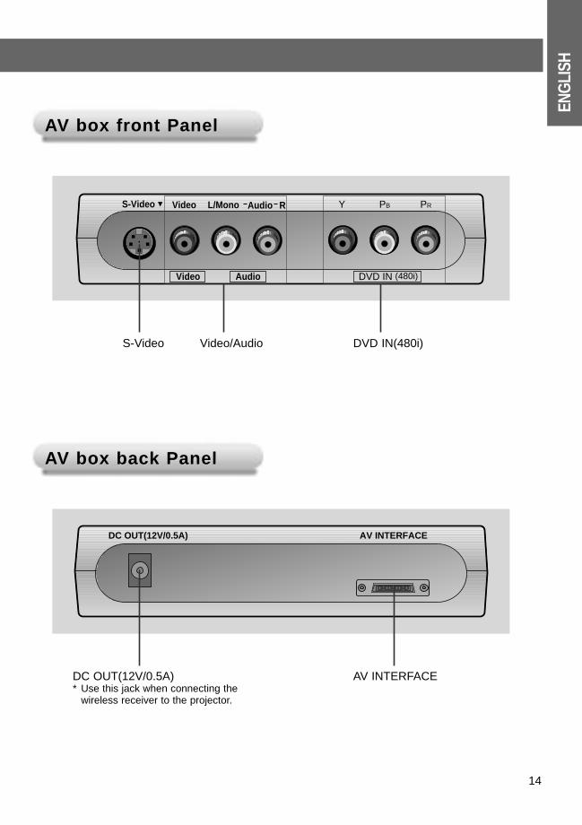
AAV box front PanelV box front Panel
AAV box back PanelV box back Panel
Y PB
DVD IN (480i)
PRVideo
Video
Audio
Audio
S-Video L/Mono R
S-Video Video/Audio DVD IN(480i)
DC OUT(12V/0.5A) AV INTERFACE
DC OUT(12V/0.5A)* Use this jack when connecting the
wireless receiver to the projector.
AV INTERFACE
15
Names of parts
POWER
SOURCE MENU
L R
BLANK MUTE
LASER
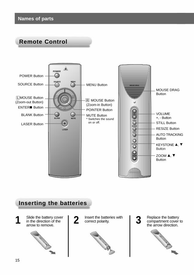
Remote Control Remote Control
Inserting the batteriesInserting the batteries
POWER Button
SOURCE Button
R MOUSE Button(Zoom-in Button)
MOUSE DRAG
VOL.
STILL
RESIZE
AUTO
KEYSTONE
ZOOM
MOUSE DRAGButton
VOLUME +, - Button
STILL Button
L MOUSE Button(Zoom-out Button)
RESIZE Button
AUTO TRACKINGButton
KEYSTONE D, EButton
ZOOM D, EButton
BLANK Button
LASER Button
Slide the battery coverin the direction of thearrow to remove.
MENU Button
ENTERA ButtonPOINTER Button
MUTE Button* Switches the sound
on or off.
1 Insert the batteries withcorrect polarity.2 Replace the battery
compartment cover tothe arrow direction.
3
ENG
LISH
Functions on the Remote ControlFunctions on the Remote Control
16
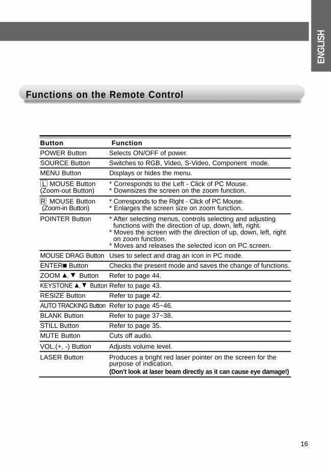
ButtonButton FunctionFunction
POWER Button Selects ON/OFF of power.
SOURCE Button Switches to RGB, Video, S-Video, Component mode.
MENU Button Displays or hides the menu.
L MOUSE Button * Corresponds to the Left - Click of PC Mouse. (Zoom-out Button) * Downsizes the screen on the zoom function.
R MOUSE Button * Corresponds to the Right - Click of PC Mouse. (Zoom-in Button) * Enlarges the screen size on zoom function.
POINTER Button * After selecting menus, controls selecting and adjusting functions with the direction of up, down, left, right.
* Moves the screen with the direction of up, down, left, right on zoom function.
* Moves and releases the selected icon on PC screen.
MOUSE DRAG Button Uses to select and drag an icon in PC mode.
ENTERA Button Checks the present mode and saves the change of functions.
ZOOM D, E Button Refer to page 44.
KEYSTONE D, E Button Refer to page 43.
RESIZE Button Refer to page 42.
AUTO TRACKING Button Refer to page 45~46.
BLANK Button Refer to page 37~38.
STILL Button Refer to page 35.
MUTE Button Cuts off audio.
VOL.(+, -) Button Adjusts volume level.
LASER Button Produces a bright red laser pointer on the screen for the purpose of indication.(Don’t look at laser beam directly as it can cause eye damage!)
Names of parts
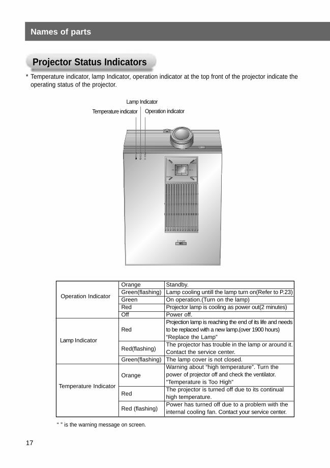
Projector Status IndicatorsProjector Status Indicators* Temperature indicator, lamp Indicator, operation indicator at the top front of the projector indicate the
operating status of the projector.
“ ” is the warning message on screen.
Orange Standby.
Operation IndicatorGreen(flashing) Lamp cooling untill the lamp turn on(Refer to P.23)Green On operation.(Turn on the lamp)Red Projector lamp is cooling as power out(2 minutes)Off Power off.
Projection lamp is reaching the end of its life and needsRed to be replaced with a new lamp.(over 1900 hours)
“Replace the Lamp”Lamp IndicatorRed(flashing)
The projector has trouble in the lamp or around it. Contact the service center.
Green(flashing) The lamp cover is not closed.
OrangeWarning about “high temperature”. Turn the power of projector off and check the ventilator.
Temperature Indicator“Temperature is Too High”
RedThe projector is turned off due to its continual high temperature.
Red (flashing)Power has turned off due to a problem with the internal cooling fan. Contact your service center.
R
MENU
SOURCE
ENTER
PATTERN
POWER
VOL VOL
Lamp Indicator
Operation indicatorTemperature indicator
17
ENG
LISH
AccessoriesAccessories
POWER
SOURCE MENU
L R
BLANK MUTE
LASER
1.5V1.5V
Mouse Connecting Cables
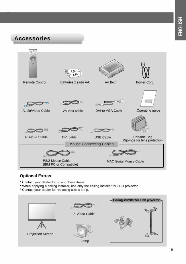
Optional Extras * Contact your dealer for buying these items.* When applying a ceiling installer, use only the ceiling installer for LCD projector.* Contact your dealer for replacing a new lamp.
Remote Control Batteries 2 (size AA) AV Box Power Cord
Audio/Video Cable AV Box cable DVI to VGA Cable
MAC Serial Mouse Cable
RS-232C cable DVI cable USB Cable Portable Bag/Sponge for lens protection
Lamp
S-Video Cable
Projection Screen
PS/2 Mouse Cable (IBM PC or Compatible)
18
Operating guide
Ceiling installer for LCD projector
19
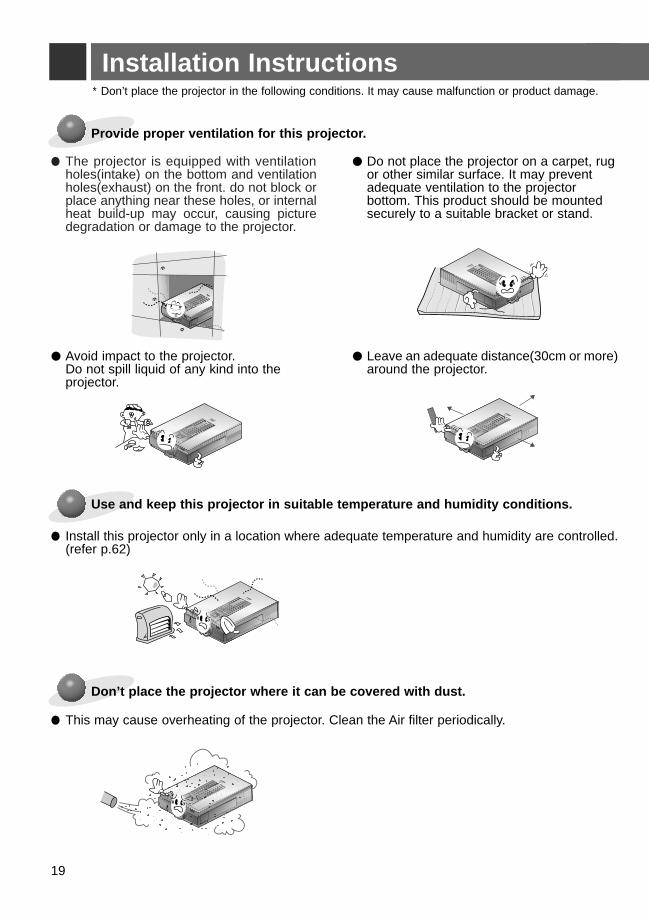
Installation Instructions
Provide proper ventilation for this projector.
● The projector is equipped with ventilationholes(intake) on the bottom and ventilationholes(exhaust) on the front. do not block orplace anything near these holes, or internalheat build-up may occur, causing picture degradation or damage to the projector.
Use and keep this projector in suitable temperature and humidity conditions.
● Install this projector only in a location where adequate temperature and humidity are controlled.(refer p.62)
● Do not place the projector on a carpet, rugor other similar surface. It may prevent adequate ventilation to the projector bottom. This product should be mounted securely to a suitable bracket or stand.
* Don’t place the projector in the following conditions. It may cause malfunction or product damage.
● Avoid impact to the projector.Do not spill liquid of any kind into the projector.
● Leave an adequate distance(30cm or more) around the projector.
Don’t place the projector where it can be covered with dust.
● This may cause overheating of the projector. Clean the Air filter periodically.
R
MENU
SOURCE
ENTER
PATTERN
POWER
VOL
VOL
R
MENU
SOURCE
ENTER
PATTERN
POWER
VOL
VOL
R
MENU
SOURCE
ENTER
PATTERN
POWER
VOL
VOL
R
MENU
SOURCE
ENTER
PATTERN
POWER
VOL
VOL
R
MENU
SOURCE
ENTER
PATTERN
POWER
VOL
VOL
R
MENU
SOURCE
ENTER
PATTERN
POWER
VOL
VOL
ENG
LISH
20
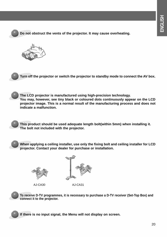
Do not obstruct the vents of the projector. It may cause overheating.
R
MENU
SOURCE
ENTER
PATTERN
POWER
VOL
VOL
The LCD projector is manufactured using high-precision technology. You may, however, see tiny black or coloured dots continuously appear on the LCDprojector image. This is a normal result of the manufacturing process and does notindicate a malfunction.
Turn off the projector or switch the projector to standby mode to connect the AV box.
To receive D-TV programmes, it is necessary to purchase a D-TV receiver (Set-Top Box) and connect it to the projector.
If there is no input signal, the Menu will not display on screen.
When applying a ceiling installer, use only the fixing bolt and ceiling installer for LCDprojector. Contact your dealer for purchase or installation.
This product should be used adequate length bolt(within 5mm) when installing it.The bolt not included with the projector.
AJ-CA30 AJ-CA31
Basic Operation of the ProjectorBasic Operation of the Projector
21
Composition
11. Place the projector on a sturdy and horizontal surface with the PC or AV source.
22. Place the projector the correct distance from the screen. The distance between the projector and the screendetermines the actual size of the image.
33. Turn the projector so that the lens can be at a right angle to the screen. If the projector is not at a right angle, thescreen image will be crooked. At this time perform keystone function.(Refer to page 43.)
44. Connect the cables of the projector to a wall power socket and other connected sources.
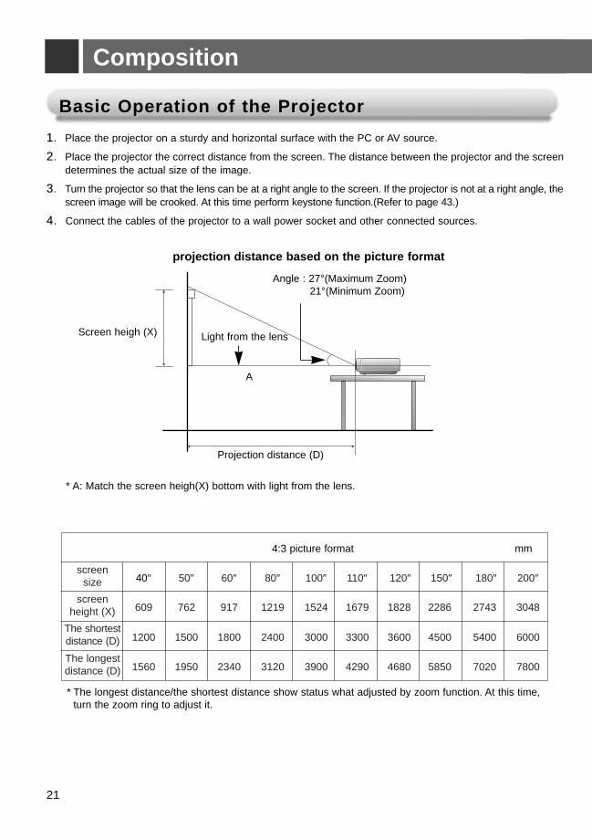
projection distance based on the picture format
* The longest distance/the shortest distance show status what adjusted by zoom function. At this time, turn the zoom ring to adjust it.
* A: Match the screen heigh(X) bottom with light from the lens.
Light from the lens
Angle : 27°(Maximum Zoom)21°(Minimum Zoom)
A
Screen heigh (X)
Projection distance (D)
4:3 picture format mm
40″ 50″ 60″ 80″ 100″ 110″ 120″ 150″ 180″ 200″
609 762 917 1219 1524 1679 1828 2286 2743 3048
1200 1500 1800 2400 3000 3300 3600 4500 5400 6000
1560 1950 2340 3120 3900 4290 4680 5850 7020 7800
screen size
screen height (X)
The shortest distance (D)
The longest distance (D)
ENG
LISH
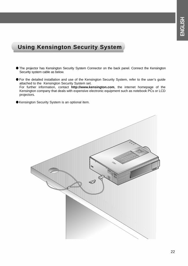
Using Kensington Security SystemUsing Kensington Security System
● The projector has Kensington Security System Connector on the back panel. Connect the KensingtonSecurity system cable as below.
● For the detailed installation and use of the Kensington Security System, refer to the user’s guideattached to the Kensington Security System set. For further information, contact http://www.kensington.com, the internet homepage of theKensington company that deals with expensive electronic equipment such as notebook PCs or LCDprojectors.
● Kensington Security System is an optional item.
R
K
R
K
22
Turning on the Projector
Remove the lens cover of the projector.2
Connect power cord correctly.1
Press the POWER button on the remote control or top cover.(Green operation indicator flashesduring cooling of the lamp.)
● It will take about 1 minute to display the picture after power on because the projector lamp has to warm up.
● An image will appear after the operation indicator light up(Green).● Select the source mode with the SOURCE button.● Leave the projector plugged in for at least 2 minutes after switching off the projector, as this
will allow the lamp cooling to continue which will help to preserve the lamp life.
3
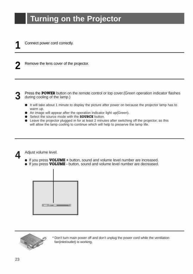
Adjust volume level.
● If you press VOLUME + button, sound and volume level number are increased.● If you press VOLUME - button, sound and volume level number are decreased.
4
24
* Don’t turn main power off and don’t unplug the power cord while the ventilationfan(inlet/outlet) is working.
R
23
ENG
LISH
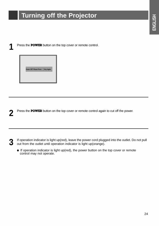
Press the POWER button on the top cover or remote control.1
Press the POWER button on the top cover or remote control again to cut off the power.2
If operation indicator is light up(red), leave the power cord plugged into the outlet. Do not pullout from the outlet until operation indicator is light up(orange).
● If operation indicator is light up(red), the power button on the top cover or remotecontrol may not operate.
3
Turning off the Projector
Power Off? Please Press Key Again.
24
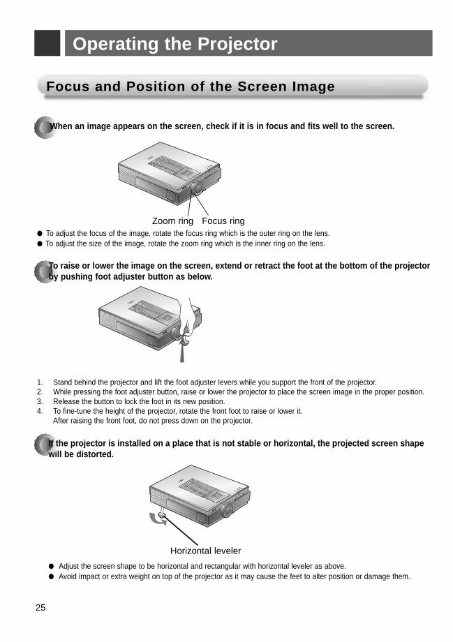
If the projector is installed on a place that is not stable or horizontal, the projected screen shapewill be distorted.
R
Horizontal leveler
● Adjust the screen shape to be horizontal and rectangular with horizontal leveler as above.● Avoid impact or extra weight on top of the projector as it may cause the feet to alter position or damage them.
Operating the Projector
Focus and Position of the Screen ImageFocus and Position of the Screen Image
When an image appears on the screen, check if it is in focus and fits well to the screen.
● To adjust the focus of the image, rotate the focus ring which is the outer ring on the lens.● To adjust the size of the image, rotate the zoom ring which is the inner ring on the lens.
To raise or lower the image on the screen, extend or retract the foot at the bottom of the projectorby pushing foot adjuster button as below.
1. Stand behind the projector and lift the foot adjuster levers while you support the front of the projector.2. While pressing the foot adjuster button, raise or lower the projector to place the screen image in the proper position.3. Release the button to lock the foot in its new position.4. To fine-tune the height of the projector, rotate the front foot to raise or lower it.
After raising the front foot, do not press down on the projector.
R
R
Focus ringZoom ring
25
ENG
LISH
26
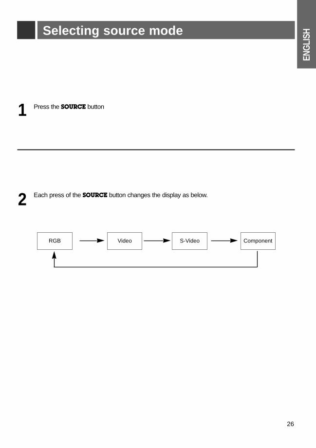
Press the SOURCE button 1
Each press of the SOURCE button changes the display as below.2
RGB Video S-Video Component
Selecting source mode
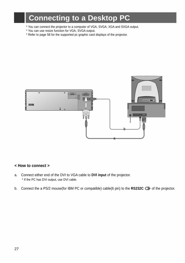
Connecting to a Desktop PC* You can connect the projector to a computer of VGA, SVGA, XGA and SXGA output. * You can use resize function for VGA, SVGA output.* Refer to page 58 for the supported pc graphic card displays of the projector.
< How to connect >
a. Connect either end of the DVI to VGA cable to DVI input of the projector.* If the PC has DVI output, use DVI cable.
b. Connect the a PS/2 mouse(for IBM PC or compatible) cable(6 pin) to the RS232C of the projector.
R
K
AV Interface DVI Input
RS 232C
a
b
27
ENG
LISH
28
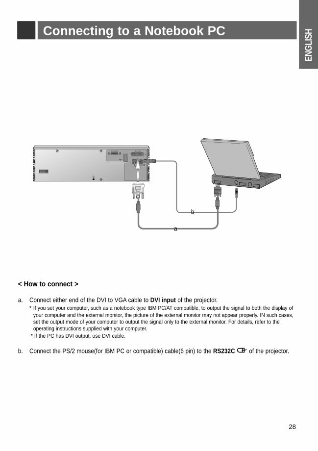
Connecting to a Notebook PC
< How to connect >
a. Connect either end of the DVI to VGA cable to DVI input of the projector.* If you set your computer, such as a notebook type IBM PC/AT compatible, to output the signal to both the display of
your computer and the external monitor, the picture of the external monitor may not appear properly. IN such cases, set the output mode of your computer to output the signal only to the external monitor. For details, refer to the operating instructions supplied with your computer.
* If the PC has DVI output, use DVI cable.
b. Connect the PS/2 mouse(for IBM PC or compatible) cable(6 pin) to the RS232C of the projector.
R
K
AV Interface DVI Input
RS 232C
a
b
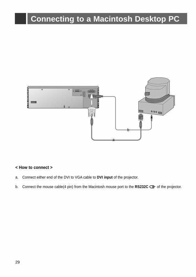
Connecting to a Macintosh Desktop PC
< How to connect >
a. Connect either end of the DVI to VGA cable to DVI input of the projector.
b. Connect the mouse cable(4 pin) from the Macintosh mouse port to the RS232C of the projector.
R
K
AV Interface DVI Input
RS 232C
b
a
29
ENG
LISH
30
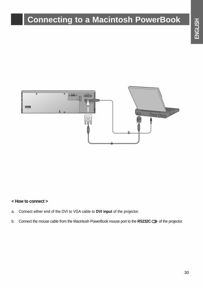
Connecting to a Macintosh PowerBook
< How to connect >
a. Connect either end of the DVI to VGA cable to DVI input of the projector.
b. Connect the mouse cable from the Macintosh PowerBook mouse port to the RS232C of the projector.
R
K
AV Interface DVI Input
RS 232C
a
b
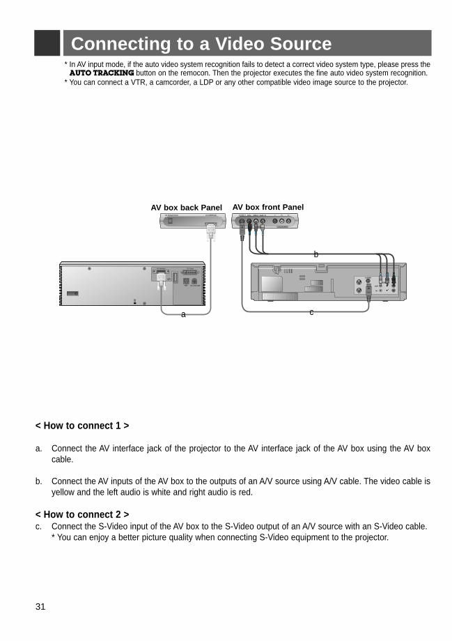
Connecting to a Video Source
< How to connect 1 >
a. Connect the AV interface jack of the projector to the AV interface jack of the AV box using the AV boxcable.
b. Connect the AV inputs of the AV box to the outputs of an A/V source using A/V cable. The video cable isyellow and the left audio is white and right audio is red.
< How to connect 2 >c. Connect the S-Video input of the AV box to the S-Video output of an A/V source with an S-Video cable.
* You can enjoy a better picture quality when connecting S-Video equipment to the projector.
* In AV input mode, if the auto video system recognition fails to detect a correct video system type, please press theAUTO TRACKING button on the remocon. Then the projector executes the fine auto video system recognition.
* You can connect a VTR, a camcorder, a LDP or any other compatible video image source to the projector.
S VIDEO
(R) AUDIO (L) VIDEO
OUT
IN
Y PB
DVD IN (480i)
PRVideo
Video
Audio
Audio
S-Video L/Mono R
R
K
AV Interface DVI Input
RS 232C
DC OUT(12V/0.5A) AV INTERFACE
a
b
c
AV box front Panel AV box back Panel
31
ENG
LISH
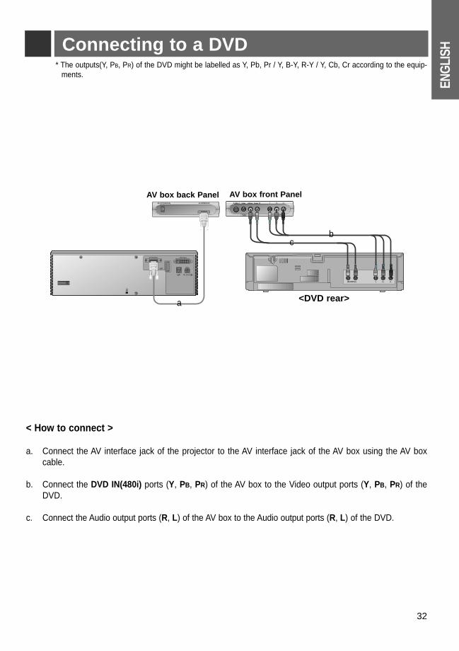
32
Connecting to a DVD* The outputs(Y, PB, PR) of the DVD might be labelled as Y, Pb, Pr / Y, B-Y, R-Y / Y, Cb, Cr according to the equip-
ments.
Y PB
DVD IN (480i)
PRVideo
Video
Audio
Audio
S-Video L/Mono R
PrPbY(R) AUDIO (L) R
K
AV Interface DVI Input
RS 232C
DC OUT(12V/0.5A) AV INTERFACE
a
b
< How to connect >
a. Connect the AV interface jack of the projector to the AV interface jack of the AV box using the AV boxcable.
b. Connect the DVD IN(480i) ports (Y, PB, PR) of the AV box to the Video output ports (Y, PB, PR) of theDVD.
c. Connect the Audio output ports (R, L) of the AV box to the Audio output ports (R, L) of the DVD.
<DVD rear>
c
AV box front Panel AV box back Panel
33
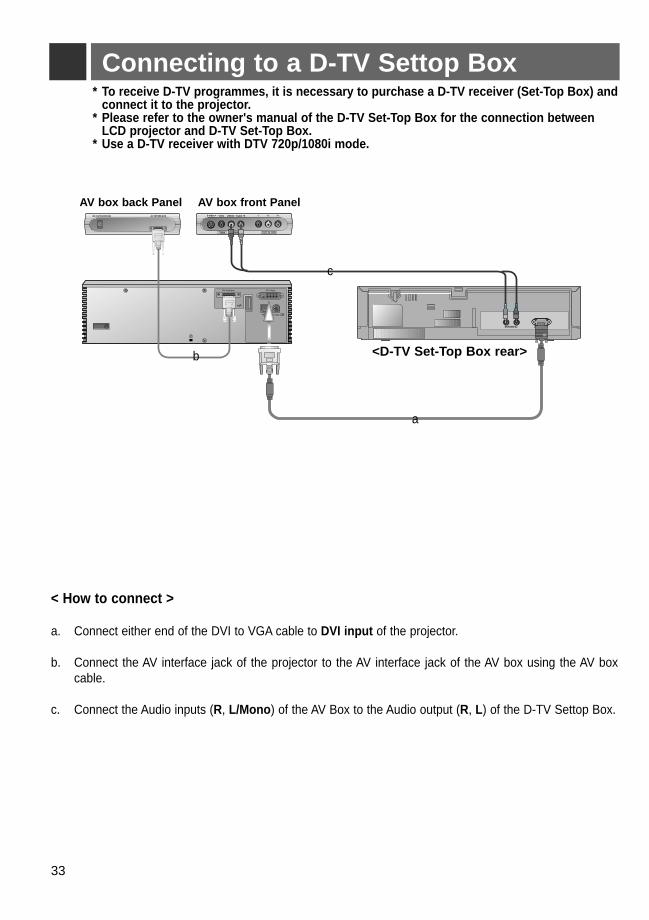
Connecting to a D-TV Settop Box
R
K
AV Interface DVI Input
RS 232C
DC OUT(12V/0.5A) AV INTERFACE Y PB
DVD IN (480i)
PRVideo
Video
Audio
Audio
S-Video L/Mono R
(R) AUDIO (L) DTV OUTPUT
< How to connect >
a. Connect either end of the DVI to VGA cable to DVI input of the projector.
b. Connect the AV interface jack of the projector to the AV interface jack of the AV box using the AV boxcable.
c. Connect the Audio inputs (R, L/Mono) of the AV Box to the Audio output (R, L) of the D-TV Settop Box.
* To receive D-TV programmes, it is necessary to purchase a D-TV receiver (Set-Top Box) and connect it to the projector.
* Please refer to the owner's manual of the D-TV Set-Top Box for the connection betweenLCD projector and D-TV Set-Top Box.
* Use a D-TV receiver with DTV 720p/1080i mode.
a
b <D-TV Set-Top Box rear>
c
AV box front Panel AV box back Panel
ENG
LISH
34
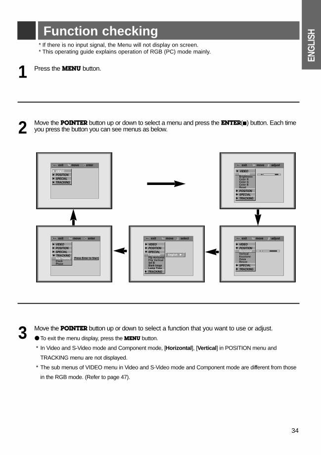
Function checking
3
Press the MENU button.1
Move the POINTER button up or down to select a menu and press the ENTER(A) button. Each timeyou press the button you can see menus as below.
Move the POINTER button up or down to select a function that you want to use or adjust.
● To exit the menu display, press the MENU button.
* In Video and S-Video mode and Component mode, [Horizontal], [Vertical] in POSITION menu and
TRACKING menu are not displayed.
* The sub menus of VIDEO menu in Video and S-Video mode and Component mode are different from those
in the RGB mode. (Refer to page 47).
2
* If there is no input signal, the Menu will not display on screen.* This operating guide explains operation of RGB (PC) mode mainly.
exit move enterMenuMenu
G VIDEOG POSITIONG SPECIALG TRACKING
exit move adjustMenuMenu
E VIDEOContrastBrightnessColor RColor GColor BReset
G POSITIONG SPECIALG TRACKING
8080
exit move adjustMenuMenu
G VIDEOE POSITION
HorizontalVerticalKeystoneZoomResize
G SPECIALG TRACKING
exit move selectMenuMenu
G VIDEOG POSITIONE SPECIAL
LanguageFlip HorizontalFlip VerticalSet IDBlank ImageLamp Time
G TRACKING
exit move enterMenuMenu
G VIDEOG POSITIONG SPECIALE TRACKING
Auto TrackingClockPhase
Press Enter to Start
00
English G
35
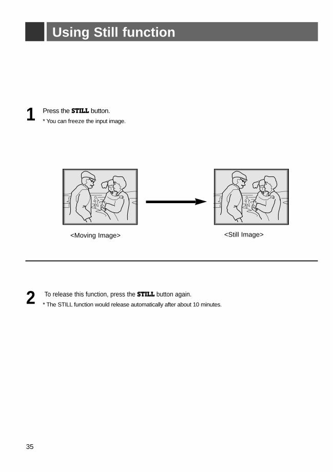
Using Still function
Press the STILL button.
* You can freeze the input image.1
To release this function, press the STILL button again.
* The STILL function would release automatically after about 10 minutes.2
<Moving Image> <Still Image>
ENG
LISH
36
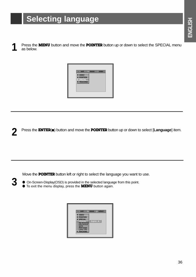
Selecting language
Press the MENU button and move the POINTER button up or down to select the SPECIAL menuas below.1
Press the ENTER(A) button and move the POINTER button up or down to select [Language] item.
Move the POINTER button left or right to select the language you want to use.
● On-Screen-Display(OSD) is provided in the selected language from this point.● To exit the menu display, press the MENU button again.
2
3
exit move enterMenuMenu
G VIDEOG POSITIONG SPECIALG TRACKING
exit move selectMenuMenu
G VIDEOG POSITIONE SPECIAL
LanguageFlip HorizontalFlip VerticalSet IDBlank ImageLamp Time
G TRACKING
English G
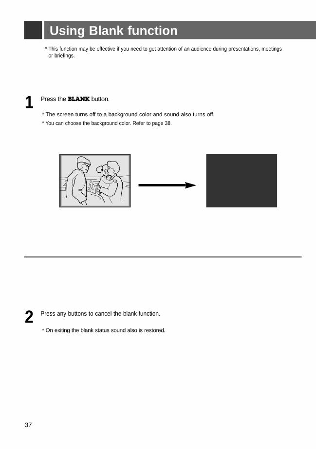
* This function may be effective if you need to get attention of an audience during presentations, meetings or briefings.
Press the BLANK button.
* The screen turns off to a background color and sound also turns off.
* You can choose the background color. Refer to page 38.
1
Press any buttons to cancel the blank function.
* On exiting the blank status sound also is restored.
2
37
Using Blank function
ENG
LISH
exit move selectMenuMenu
G VIDEOG POSITIONE SPECIAL
LanguageFlip HorizontalFlip VerticalSet IDBlank ImageLamp Time
G TRACKING
Blue G
38
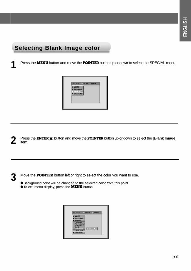
Selecting Blank Image colorSelecting Blank Image color
Press the MENU button and move the POINTER button up or down to select the SPECIAL menu. 1
Press the ENTER(A) button and move the POINTER button up or down to select the [Blank Image]item.2
Move the POINTER button left or right to select the color you want to use.
● Background color will be changed to the selected color from this point.● To exit menu display, press the MENU button.
3
exit move enterMenuMenu
G VIDEOG POSITIONG SPECIALG TRACKING
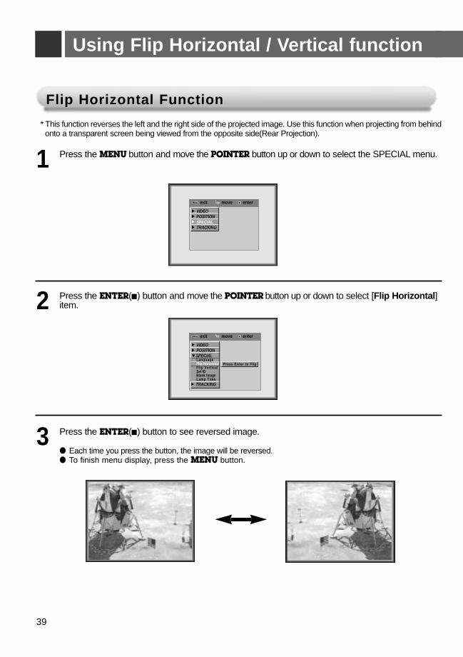
Using Flip Horizontal / Vertical function
Flip Horizontal FunctionFlip Horizontal Function
Press the MENU button and move the POINTER button up or down to select the SPECIAL menu.1
Press the ENTER(A) button and move the POINTER button up or down to select [Flip Horizontal]item.2
Press the ENTER(A) button to see reversed image.
● Each time you press the button, the image will be reversed.● To finish menu display, press the MENU button.
3
* This function reverses the left and the right side of the projected image. Use this function when projecting from behind onto a transparent screen being viewed from the opposite side(Rear Projection).
exit move enterMenuMenu
G VIDEOG POSITIONG SPECIALG TRACKING
exit move enterMenuMenu
G VIDEOG POSITIONESPECIAL
LanguageFlip HorizontalFlip VerticalSet IDBlank ImageLamp Time
G TRACKING
Press Enter to Flip
39
ENG
LISH
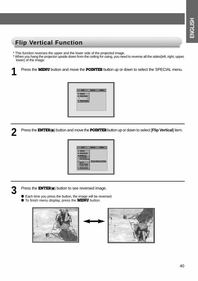
Flip VFlip Vertical Functionertical Function
Press the MENU button and move the POINTER button up or down to select the SPECIAL menu.1
Press the ENTER(A) button and move the POINTER button up or down to select [Flip Vertical] item.2
Press the ENTER(A) button to see reversed image.
● Each time you press the button, the image will be reversed.● To finish menu display, press the MENU button.
3
* This function reverses the upper and the lower side of the projected image. * When you hang the projector upside down from the ceiling for using, you need to reverse all the sides(left, right, upper,
lower) of the image.
exit move enterMenuMenu
G VIDEOG POSITIONG SPECIALG TRACKING
exit move enterMenuMenu
G VIDEOG POSITIONESPECIAL
LanguageFlip HorizontalFlip VerticalSet IDBlank ImageLamp Time
G TRACKING
Press Enter to Flip
40
41
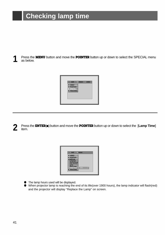
Checking lamp time
Press the MENU button and move the POINTER button up or down to select the SPECIAL menuas below.1
Press the ENTER(A) button and move the POINTER button up or down to select the [Lamp Time]item.2
● The lamp hours used will be displayed.● When projector lamp is reaching the end of its life(over 1900 hours), the lamp indicator will flash(red)
and the projector will display “Replace the Lamp” on screen.
exit move enterMenuMenu
G VIDEOG POSITIONG SPECIALG TRACKING
exit move MenuMenu
G VIDEOG POSITIONESPECIAL
LanguageFlip HorizontalFlip VerticalSet IDBlank ImageLamp Time
G TRACKING0 Hr
ENG
LISH
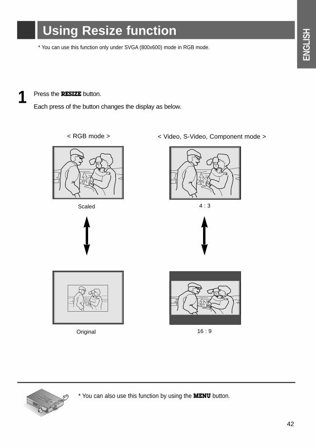
42
Using Resize function* You can use this function only under SVGA (800x600) mode in RGB mode.
* You can also use this function by using the MENU button.R
Press the RESIZE button.
Each press of the button changes the display as below.1
Scaled 4 : 3
Original 16 : 9
< RGB mode > < Video, S-Video, Component mode >
43
Adjusting screen display
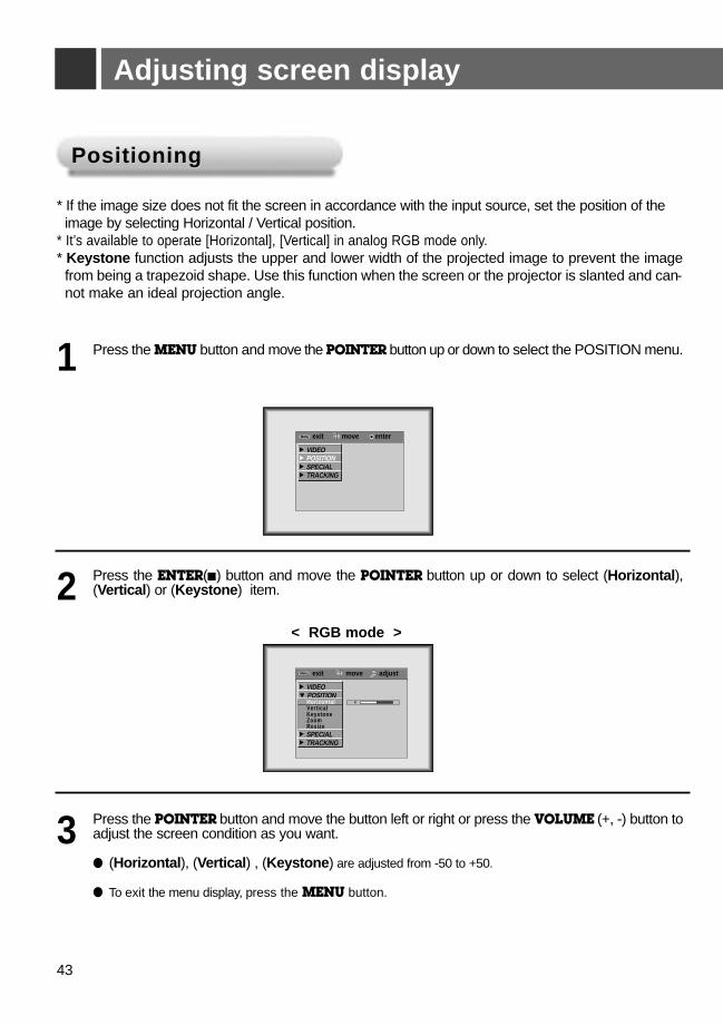
PositioningPositioning
Press the MENU button and move the POINTER button up or down to select the POSITION menu. 1
Press the ENTER(A) button and move the POINTER button up or down to select (Horizontal),(Vertical) or (Keystone) item.
* If the image size does not fit the screen in accordance with the input source, set the position of the image by selecting Horizontal / Vertical position.
* It’s available to operate [Horizontal], [Vertical] in analog RGB mode only.* Keystone function adjusts the upper and lower width of the projected image to prevent the image
from being a trapezoid shape. Use this function when the screen or the projector is slanted and can-not make an ideal projection angle.
2
Press the POINTER button and move the button left or right or press the VOLUME (+, -) button toadjust the screen condition as you want.
● (Horizontal), (Vertical) , (Keystone) are adjusted from -50 to +50.
● To exit the menu display, press the MENU button.
3
exit move adjustMenuMenu
G VIDEOE POSITION
HorizontalVerticalKeystoneZoomResize
G SPECIALG TRACKING
00
exit move enterMenuMenu
G VIDEOG POSITIONG SPECIALG TRACKING
< RGB mode >
ENG
LISH
44
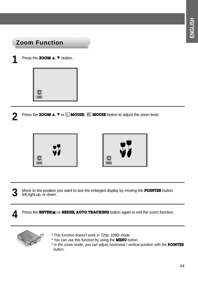
Zoom FunctionZoom Function
Press the ZOOM D, E button.1
Move to the position you want to see the enlarged display by moving the POINTER buttonleft,right,up, or down.3
Press the ENTER(A) or RESIZE, AUTO TRACKING button again to exit the zoom function.4
Press the ZOOM D, E or L MOUSE, R MOUSE button to adjust the zoom level.2
* This function doesn’t work in 720p, 1080i mode.* You can use this function by using the MENU button.* In the zoom mode, you can adjust horizontal / vertical position with the POINTER
button.
R
11/25 25/25
1/25
45
TITLEUsing Tracking function
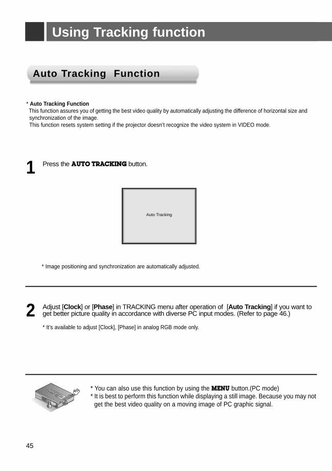
* Auto Tracking FunctionThis function assures you of getting the best video quality by automatically adjusting the difference of horizontal size andsynchronization of the image. This function resets system setting if the projector doesn’t recognize the video system in VIDEO mode.
* Image positioning and synchronization are automatically adjusted.
Press the AUTO TRACKING button.1
Adjust [Clock] or [Phase] in TRACKING menu after operation of [Auto Tracking] if you want toget better picture quality in accordance with diverse PC input modes. (Refer to page 46.)
* It’s available to adjust [Clock], [Phase] in analog RGB mode only.
2
* You can also use this function by using the MENU button.(PC mode)* It is best to perform this function while displaying a still image. Because you may not
get the best video quality on a moving image of PC graphic signal. R
Auto Tracking
Auto TAuto Tracking Functionracking Function
ENG
LISH
46
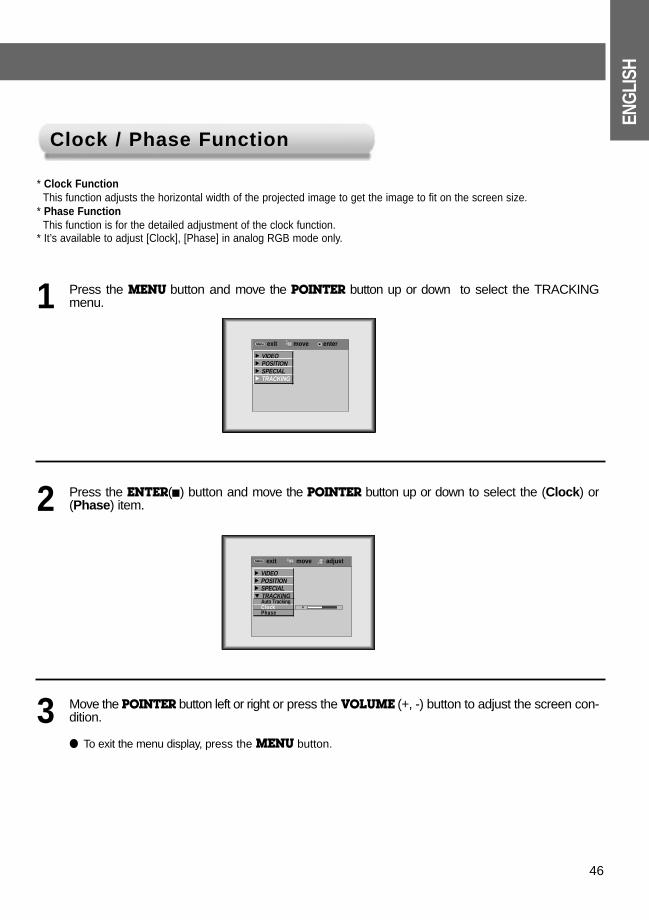
* Clock FunctionThis function adjusts the horizontal width of the projected image to get the image to fit on the screen size.
* Phase FunctionThis function is for the detailed adjustment of the clock function.
* It’s available to adjust [Clock], [Phase] in analog RGB mode only.
Press the MENU button and move the POINTER button up or down to select the TRACKINGmenu. 1
Press the ENTER(A) button and move the POINTER button up or down to select the (Clock) or(Phase) item.2
Clock / Phase FunctionClock / Phase Function
Move the POINTER button left or right or press the VOLUME (+, -) button to adjust the screen con-dition.
● To exit the menu display, press the MENU button.
3
exit move adjustMenuMenu
G VIDEOG POSITIONG SPECIALE TRACKING
Auto TrackingClockPhase
00
exit move enterMenuMenu
G VIDEOG POSITIONG SPECIALG TRACKING
47
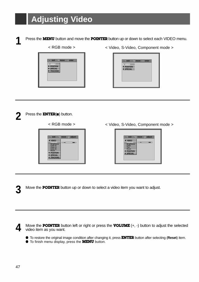
Adjusting Video
Press the MENU button and move the POINTER button up or down to select each VIDEO menu. 1
Move the POINTER button up or down to select a video item you want to adjust.3
Move the POINTER button left or right or press the VOLUME (+, -) button to adjust the selectedvideo item as you want.
● To restore the original image condition after changing it, press ENTER button after selecting (Reset) item.● To finish menu display, press the MENU button.
4
Press the ENTER(A) button.2
exit move adjustMenuMenu
E VIDEOContrastBrightnessColor RColor GColor BReset
G POSITIONG SPECIALG TRACKING
8080
exit move adjustMenuMenu
E VIDEOContrastBrightnessColorTintReset
G POSITIONG SPECIAL
8080
exit move enterMenuMenu
G VIDEOG POSITIONG SPECIALG TRACKING
exit move enterMenuMenu
G VIDEOG POSITIONG SPECIAL
< RGB mode > < Video, S-Video, Component mode >
< RGB mode > < Video, S-Video, Component mode >
ENG
LISH
48
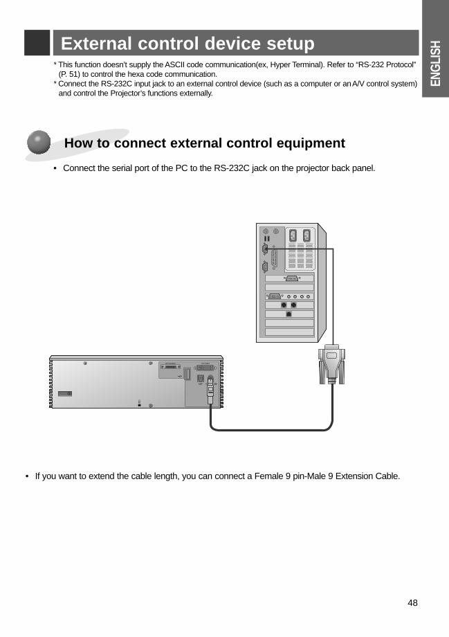
External control device setup
• Connect the serial port of the PC to the RS-232C jack on the projector back panel.
How to connect external control equipment
* This function doesn’t supply the ASCII code communication(ex, Hyper Terminal). Refer to “RS-232 Protocol”(P. 51) to control the hexa code communication.
* Connect the RS-232C input jack to an external control device (such as a computer or an A/V control system)and control the Projector’s functions externally.
• If you want to extend the cable length, you can connect a Female 9 pin-Male 9 Extension Cable.
R
K
AV Interface DVI Input
RS 232C
1
2
3
4
9
SHELL
PROJECTOR
MD8P(Circular Din 8P, male)
DE9S(D-Sub 9 Pin, female)
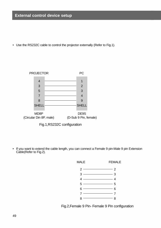
Fig.1,RS232C configuration
Fig.2,Female 9 Pin- Female 9 Pin configuration
PC
4
3
5
7
8
SHELL
• If you want to extend the cable length, you can connect a Female 9 pin-Male 9 pin ExtensionCable(Refer to Fig.2).
MALE FEMALE
2
3
4
5
6
7
8
2
3
4
5
6
7
8
49
External control device setup
• Use the RS232C cable to control the projector externally (Refer to Fig.1).
ENG
LISH
50
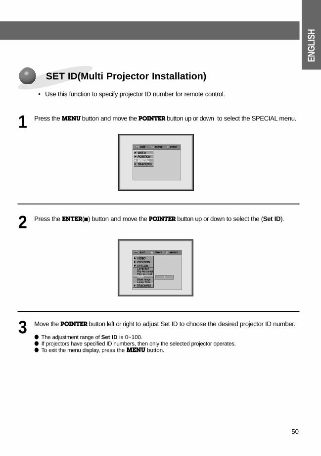
• Use this function to specify projector ID number for remote control.
SET ID(Multi Projector Installation)
Press the MENU button and move the POINTER button up or down to select the SPECIAL menu. 1
Press the ENTER(A) button and move the POINTER button up or down to select the (Set ID).2
Move the POINTER button left or right to adjust Set ID to choose the desired projector ID number.
● The adjustment range of Set ID is 0~100. ● If projectors have specified ID numbers, then only the selected projector operates.● To exit the menu display, press the MENU button.
3
exit move enterMenuMenu
G VIDEOG POSITIONG SPECIALG TRACKING
exit move selectMenuMenu
G VIDEOG POSITIONE SPECIAL
LanguageFlip HorizontalFlip VerticalSet IDBlank ImageLamp Time
G TRACKING
1
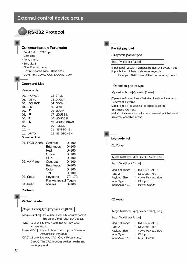
Communication Parameter• Baud Rate : 19200 bps• Data bit:8• Parity : none• Stop bit : 1• Flow Control : none• Communication code : Hexa code• COM Port : COM1, COM2, COM3, COM4
Packet header
[Magic Number][Type][Payload Size][CRC]
Command List
Key-code List
01. POWER02. MENU03. SOURCE04. ENTER05. E
06. F
07. G
08. D
09. -10. +11. AUTO
12. STILL13. ZOOM -14. ZOOM +15. MUTE16. BLANK17. MOUSE L18. MOUSE R19. MOUSE DRAG20. RESIZE21. KEYSTONE -22. KEYSTONE +
Operating List
Protocol
[Magic Number] : It’s a default value to confirm packet line up of 2 byte (0xEFBD-Set ID).
[Type] : 1 byte. It shows type of packet (key-code or operation).
[Payload Size] : 2 byte. It shows a data byte of CommandData (Packet Payload).
[CRC] : 2 byte. It shows CRC (Cyclic RedundancyCheck). The CRC includes packet header andpacketpayload.
Packet payload
- Keycode packet type
[Input Type][Input Action]
[Input Type] : 2 byte. It displays IR input or Keypad input.[Input Action] : 2 byte. It shows a Keycode.
Example : 0x25 shows left arrow button operation.
- Operation packet type
[Operation Action][Operation][Value]
[Operation Action]: It sets Set, Get, Initialize, Increment,Defrement, Execute.[Operation] : It shows GUI operation ,such asBrightness, Contrast.[Value] : It shows a value for set command which doesn’tuse other operation action.
key-code list
01.Power
[Magic Number][Type][Payload Size][CRC]
[Input Type][Input Action]
Magic Number : 0xEFBD-Set IDType 2 : Keycode TypePayload Size 4 : 4byte Payload sizeInput Type 1 : IR InputInput Action 18 : Power On/Off
02.Menu
[Magic Number][Type][Payload Size][CRC]
[Input Type][Input Action]
Magic Number : 0xEFBD-Set IDType 2 : Keycode TypePayload Size 4 : 4byte Payload sizeInput Type 1 : IR InputInput Action 17 : Menu On/Off
01. RGB Video
02. AV Video
03. Setup
04.Audio
ContrastBrightnessRedGreenBlueContrastBrightnessColorTintKeystoneFlip HorizontalVolume
0~1000~1000~1000~1000~1000~1000~1000~1000~10078~178Toggle0~100
51
External control device setup
RS-232 Protocol
ENG
LISH
52
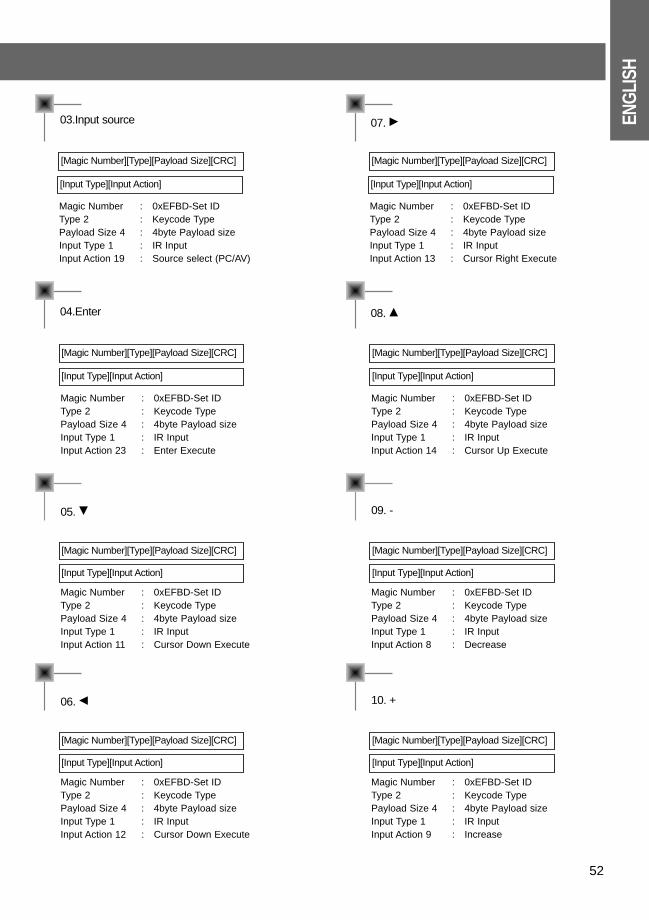
03.Input source
04.Enter
[Magic Number][Type][Payload Size][CRC]
[Input Type][Input Action]
Magic Number : 0xEFBD-Set IDType 2 : Keycode TypePayload Size 4 : 4byte Payload sizeInput Type 1 : IR InputInput Action 19 : Source select (PC/AV)
[Magic Number][Type][Payload Size][CRC]
[Input Type][Input Action]
Magic Number : 0xEFBD-Set IDType 2 : Keycode TypePayload Size 4 : 4byte Payload sizeInput Type 1 : IR InputInput Action 23 : Enter Execute
05. E
[Magic Number][Type][Payload Size][CRC]
[Input Type][Input Action]
Magic Number : 0xEFBD-Set IDType 2 : Keycode TypePayload Size 4 : 4byte Payload sizeInput Type 1 : IR InputInput Action 11 : Cursor Down Execute
06. F
[Magic Number][Type][Payload Size][CRC]
[Input Type][Input Action]
Magic Number : 0xEFBD-Set IDType 2 : Keycode TypePayload Size 4 : 4byte Payload sizeInput Type 1 : IR InputInput Action 12 : Cursor Down Execute
07. G
08. D
[Magic Number][Type][Payload Size][CRC]
[Input Type][Input Action]
Magic Number : 0xEFBD-Set IDType 2 : Keycode TypePayload Size 4 : 4byte Payload sizeInput Type 1 : IR InputInput Action 13 : Cursor Right Execute
[Magic Number][Type][Payload Size][CRC]
[Input Type][Input Action]
Magic Number : 0xEFBD-Set IDType 2 : Keycode TypePayload Size 4 : 4byte Payload sizeInput Type 1 : IR InputInput Action 14 : Cursor Up Execute
09. -
[Magic Number][Type][Payload Size][CRC]
[Input Type][Input Action]
Magic Number : 0xEFBD-Set IDType 2 : Keycode TypePayload Size 4 : 4byte Payload sizeInput Type 1 : IR InputInput Action 8 : Decrease
10. +
[Magic Number][Type][Payload Size][CRC]
[Input Type][Input Action]
Magic Number : 0xEFBD-Set IDType 2 : Keycode TypePayload Size 4 : 4byte Payload sizeInput Type 1 : IR InputInput Action 9 : Increase
53
External control device setup
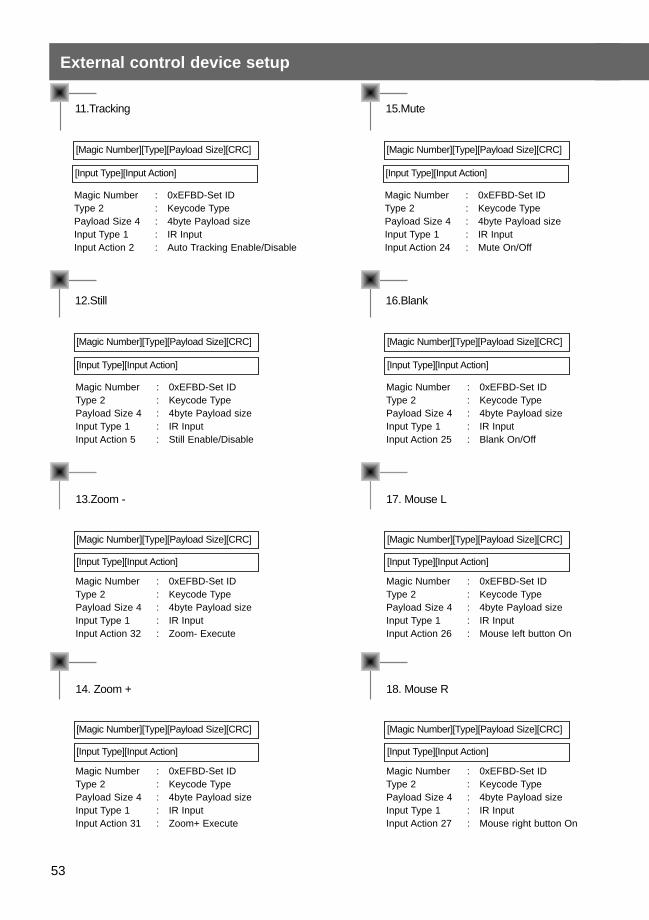
11.Tracking
12.Still
[Magic Number][Type][Payload Size][CRC]
[Input Type][Input Action]
Magic Number : 0xEFBD-Set IDType 2 : Keycode TypePayload Size 4 : 4byte Payload sizeInput Type 1 : IR InputInput Action 2 : Auto Tracking Enable/Disable
[Magic Number][Type][Payload Size][CRC]
[Input Type][Input Action]
Magic Number : 0xEFBD-Set IDType 2 : Keycode TypePayload Size 4 : 4byte Payload sizeInput Type 1 : IR InputInput Action 5 : Still Enable/Disable
13.Zoom -
[Magic Number][Type][Payload Size][CRC]
[Input Type][Input Action]
Magic Number : 0xEFBD-Set IDType 2 : Keycode TypePayload Size 4 : 4byte Payload sizeInput Type 1 : IR InputInput Action 32 : Zoom- Execute
14. Zoom +
[Magic Number][Type][Payload Size][CRC]
[Input Type][Input Action]
Magic Number : 0xEFBD-Set IDType 2 : Keycode TypePayload Size 4 : 4byte Payload sizeInput Type 1 : IR InputInput Action 31 : Zoom+ Execute
15.Mute
16.Blank
[Magic Number][Type][Payload Size][CRC]
[Input Type][Input Action]
Magic Number : 0xEFBD-Set IDType 2 : Keycode TypePayload Size 4 : 4byte Payload sizeInput Type 1 : IR InputInput Action 24 : Mute On/Off
[Magic Number][Type][Payload Size][CRC]
[Input Type][Input Action]
Magic Number : 0xEFBD-Set IDType 2 : Keycode TypePayload Size 4 : 4byte Payload sizeInput Type 1 : IR InputInput Action 25 : Blank On/Off
17. Mouse L
[Magic Number][Type][Payload Size][CRC]
[Input Type][Input Action]
Magic Number : 0xEFBD-Set IDType 2 : Keycode TypePayload Size 4 : 4byte Payload sizeInput Type 1 : IR InputInput Action 26 : Mouse left button On
18. Mouse R
[Magic Number][Type][Payload Size][CRC]
[Input Type][Input Action]
Magic Number : 0xEFBD-Set IDType 2 : Keycode TypePayload Size 4 : 4byte Payload sizeInput Type 1 : IR InputInput Action 27 : Mouse right button On
ENG
LISH
54
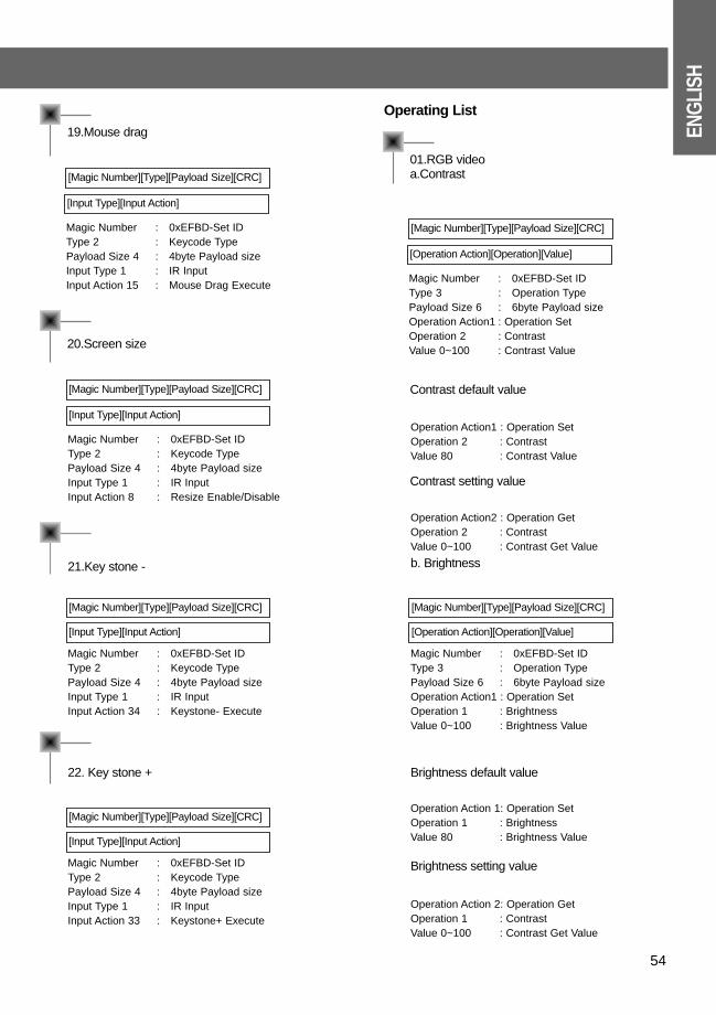
19.Mouse drag
20.Screen size
[Magic Number][Type][Payload Size][CRC]
[Input Type][Input Action]
Magic Number : 0xEFBD-Set IDType 2 : Keycode TypePayload Size 4 : 4byte Payload sizeInput Type 1 : IR InputInput Action 15 : Mouse Drag Execute
[Magic Number][Type][Payload Size][CRC]
[Input Type][Input Action]
Magic Number : 0xEFBD-Set IDType 2 : Keycode TypePayload Size 4 : 4byte Payload sizeInput Type 1 : IR InputInput Action 8 : Resize Enable/Disable
21.Key stone -
[Magic Number][Type][Payload Size][CRC]
[Input Type][Input Action]
Magic Number : 0xEFBD-Set IDType 2 : Keycode TypePayload Size 4 : 4byte Payload sizeInput Type 1 : IR InputInput Action 34 : Keystone- Execute
22. Key stone +
[Magic Number][Type][Payload Size][CRC]
[Input Type][Input Action]
Magic Number : 0xEFBD-Set IDType 2 : Keycode TypePayload Size 4 : 4byte Payload sizeInput Type 1 : IR InputInput Action 33 : Keystone+ Execute
01.RGB videoa.Contrast
Operating List
Contrast default value
[Magic Number][Type][Payload Size][CRC]
[Operation Action][Operation][Value]
Magic Number : 0xEFBD-Set IDType 3 : Operation TypePayload Size 6 : 6byte Payload size Operation Action1 : Operation SetOperation 2 : ContrastValue 0~100 : Contrast Value
Operation Action1 : Operation SetOperation 2 : ContrastValue 80 : Contrast Value
Contrast setting value
Operation Action2 : Operation GetOperation 2 : ContrastValue 0~100 : Contrast Get Value
b. Brightness
[Magic Number][Type][Payload Size][CRC]
[Operation Action][Operation][Value]
Magic Number : 0xEFBD-Set IDType 3 : Operation TypePayload Size 6 : 6byte Payload size Operation Action1 : Operation SetOperation 1 : BrightnessValue 0~100 : Brightness Value
Brightness default value
Operation Action 1: Operation SetOperation 1 : BrightnessValue 80 : Brightness Value
Brightness setting value
Operation Action 2: Operation GetOperation 1 : ContrastValue 0~100 : Contrast Get Value
55
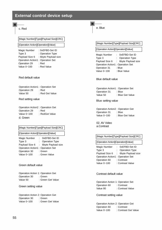
External control device setup
c. Red
[Magic Number][Type][Payload Size][CRC]
[Operation Action][Operation][Value]
Magic Number : 0xEFBD-Set IDType 3 : Operation TypePayload Size 6 : 6byte Payload sizeOperation Action1 : Operation SetOperation 29 : RedValue 0~100 : Red Value
e. Blue
Blue default value
[Magic Number][Type][Payload Size][CRC]
[Operation Action][Operation][Value]
Magic Number : 0xEFBD-Set IDType 3 : Operation TypePayload Size 6 : 6byte Payload size Operation Action1 : Operation SetOperation 31 : BlueValue 0~100 : Blue Value
Operation Action1 : Operation SetOperation 31 : BlueValue 50 : Blue Get Value
Blue setting value
Operation Action2 : Operation GetOperation 31 : BlueValue 0~100 : Blue Get Value
02. AV Videoa.Contrast
[Magic Number][Type][Payload Size][CRC]
[Operation Action][Operation][Value]
Magic Number : 0xEFBD-Set IDType 3 : Operation TypePayload Size 6 : 6byte Payload size Operation Action1 : Operation SetOperation 60 : ContrastValue 0~100 : Contrast Value
Contrast default value
Operation Action 1: Operation SetOperation 60 : Contrast Value 80 : Contrast Value
Contrast setting value
Operation Action 2: Operation GetOperation 60 : ContrastValue 0~100 : Contrast Get Value
Red default value
Operation Action1 : Operation SetOperation 29 : RedValue 50 : Red Get Value
Red setting value
Operation Action2 : Operation GetOperation 29 : RedValue 0~100 : RedGet Value
d. Green
[Magic Number][Type][Payload Size][CRC]
[Operation Action][Operation][Value]
Magic Number : 0xEFBD-Set IDType 3 : Operation TypePayload Size 6 : 6byte Payload sizeOperation Action1 : Operation SetOperation 30 : GreenValue 0~100 : Green Value
Green default value
Operation Action 1: Operation GetOperation 30 : GreenValue 50 : Green Get Value
Green setting value
Operation Action 2: Operation GetOperation 30 : GreenValue 0~100 : Green Get Value
ENG
LISH
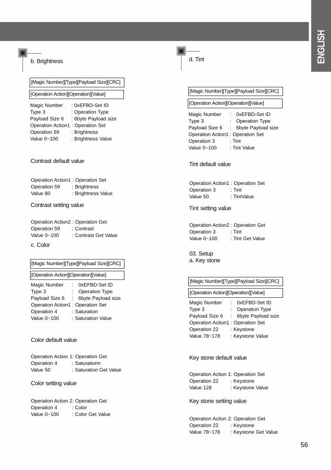
56
b. Brightness
[Magic Number][Type][Payload Size][CRC]
[Operation Action][Operation][Value]
Magic Number : 0xEFBD-Set IDType 3 : Operation TypePayload Size 6 : 6byte Payload sizeOperation Action1 : Operation SetOperation 59 : BrightnessValue 0~100 : Brightness Value
d. Tint
Tint default value
[Magic Number][Type][Payload Size][CRC]
[Operation Action][Operation][Value]
Magic Number : 0xEFBD-Set IDType 3 : Operation TypePayload Size 6 : 6byte Payload size Operation Action1 : Operation SetOperation 3 : TintValue 0~100 : Tint Value
Operation Action1 : Operation SetOperation 3 : TintValue 50 : TintValue
Tint setting value
Operation Action2 : Operation GetOperation 3 : TintValue 0~100 : Tint Get Value
03. Setupa. Key stone
[Magic Number][Type][Payload Size][CRC]
[Operation Action][Operation][Value]
Magic Number : 0xEFBD-Set IDType 3 : Operation TypePayload Size 6 : 6byte Payload size Operation Action1 : Operation SetOperation 22 : KeystoneValue 78~178 : Keystone Value
Key stone default value
Operation Action 1: Operation SetOperation 22 : KeystoneValue 128 : Keystone Value
Key stone setting value
Operation Action 2: Operation GetOperation 22 : KeystoneValue 78~178 : Keystone Get Value
Contrast default value
Operation Action1 : Operation SetOperation 59 : BrightnessValue 80 : Brightness Value
Contrast setting value
Operation Action2 : Operation GetOperation 59 : ContrastValue 0~100 : Contrast Get Value
c. Color
[Magic Number][Type][Payload Size][CRC]
[Operation Action][Operation][Value]
Magic Number : 0xEFBD-Set IDType 3 : Operation TypePayload Size 6 : 6byte Payload size Operation Action1 : Operation SetOperation 4 : SaturationValue 0~100 : Saturation Value
Color default value
Operation Action 1: Operation GetOperation 4 : SaturationnValue 50 : Saturation Get Value
Color setting value
Operation Action 2: Operation GetOperation 4 : ColorValue 0~100 : Color Get Value
57
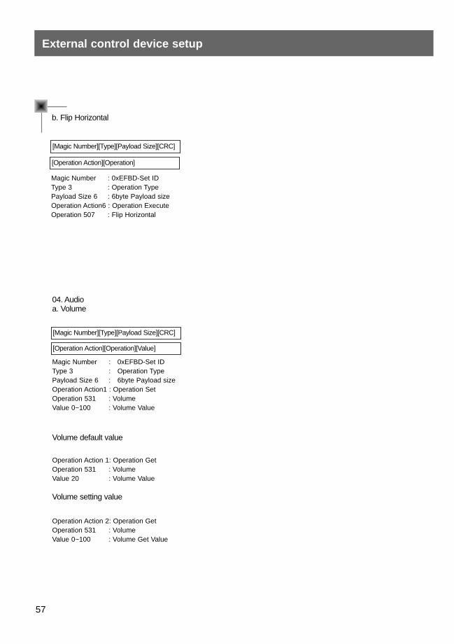
External control device setup
b. Flip Horizontal
[Magic Number][Type][Payload Size][CRC]
[Operation Action][Operation]
Magic Number : 0xEFBD-Set IDType 3 : Operation TypePayload Size 6 : 6byte Payload sizeOperation Action6 : Operation ExecuteOperation 507 : Flip Horizontal
04. Audioa. Volume
[Magic Number][Type][Payload Size][CRC]
[Operation Action][Operation][Value]
Magic Number : 0xEFBD-Set IDType 3 : Operation TypePayload Size 6 : 6byte Payload sizeOperation Action1 : Operation SetOperation 531 : VolumeValue 0~100 : Volume Value
Volume default value
Operation Action 1: Operation GetOperation 531 : VolumeValue 20 : Volume Value
Volume setting value
Operation Action 2: Operation GetOperation 531 : VolumeValue 0~100 : Volume Get Value
ENG
LISH
58
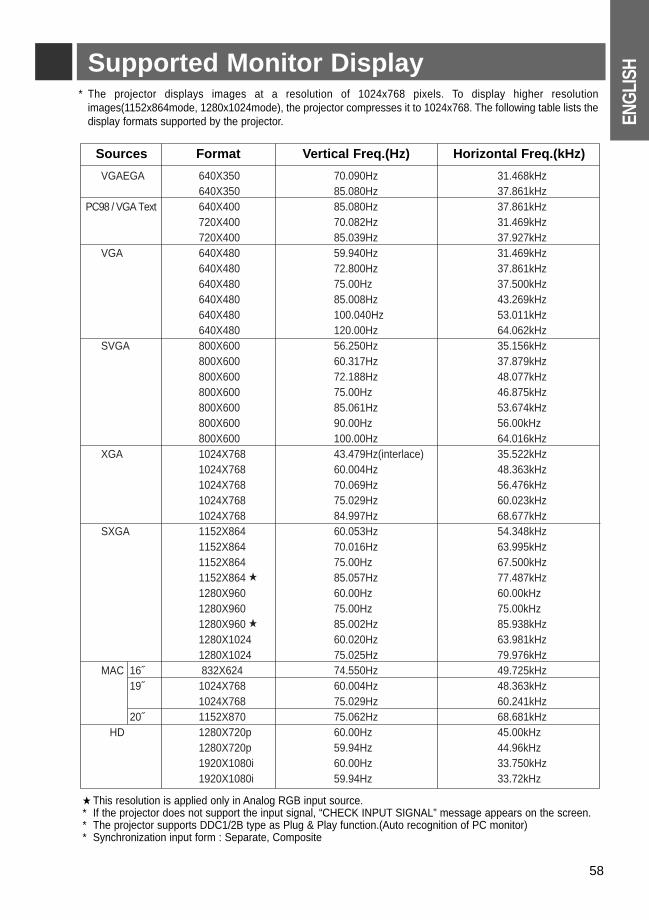
Supported Monitor Display* The projector displays images at a resolution of 1024x768 pixels. To display higher resolution
images(1152x864mode, 1280x1024mode), the projector compresses it to 1024x768. The following table lists thedisplay formats supported by the projector.
★ This resolution is applied only in Analog RGB input source.* If the projector does not support the input signal, “CHECK INPUT SIGNAL” message appears on the screen.* The projector supports DDC1/2B type as Plug & Play function.(Auto recognition of PC monitor)* Synchronization input form : Separate, Composite
VGAEGA 640X350 70.090Hz 31.468kHz640X350 85.080Hz 37.861kHz
PC98 / VGA Text 640X400 85.080Hz 37.861kHz720X400 70.082Hz 31.469kHz720X400 85.039Hz 37.927kHz
VGA 640X480 59.940Hz 31.469kHz640X480 72.800Hz 37.861kHz640X480 75.00Hz 37.500kHz640X480 85.008Hz 43.269kHz640X480 100.040Hz 53.011kHz640X480 120.00Hz 64.062kHz
SVGA 800X600 56.250Hz 35.156kHz800X600 60.317Hz 37.879kHz800X600 72.188Hz 48.077kHz800X600 75.00Hz 46.875kHz800X600 85.061Hz 53.674kHz800X600 90.00Hz 56.00kHz800X600 100.00Hz 64.016kHz
XGA 1024X768 43.479Hz(interlace) 35.522kHz1024X768 60.004Hz 48.363kHz1024X768 70.069Hz 56.476kHz1024X768 75.029Hz 60.023kHz1024X768 84.997Hz 68.677kHz
SXGA 1152X864 60.053Hz 54.348kHz1152X864 70.016Hz 63.995kHz1152X864 75.00Hz 67.500kHz1152X864 ★ 85.057Hz 77.487kHz1280X960 60.00Hz 60.00kHz1280X960 75.00Hz 75.00kHz1280X960 ★ 85.002Hz 85.938kHz1280X1024 60.020Hz 63.981kHz1280X1024 75.025Hz 79.976kHz
MAC 16˝ 832X624 74.550Hz 49.725kHz19˝ 1024X768 60.004Hz 48.363kHz
1024X768 75.029Hz 60.241kHz20˝ 1152X870 75.062Hz 68.681kHz
HD 1280X720p 60.00Hz 45.00kHz1280X720p 59.94Hz 44.96kHz1920X1080i 60.00Hz 33.750kHz1920X1080i 59.94Hz 33.72kHz
Sources Format Vertical Freq.(Hz) Horizontal Freq.(kHz)
Maintenance* The projector needs little maintenance. You should keep the lens clean because any dirt or stains may appear
on the screen. You will also need to clean the air filter attached at the top of the projector periodically becausea clogged air filter prevents proper ventilation that is necessary to cool the projector and prevents it from overheating. If any parts need to be replaced, contact your dealer. When cleaning any part of the pro-jector, always turn the power off and unplug the projector first.
Cleaning the lensCleaning the lens
Clean the lens whenever you notice dirt or dust on the surface of it. Wipe the lens surface gently with an air spray or a soft, dry lint-free cloth.To remove dirt or stains on the lens, moisten a soft cloth with water and a neutral detergent and wipe the lens surface gently.
Cleaning the Projector CaseCleaning the Projector Case
To clean the projector case, first unplug the power cable. To remove dirt or dust, wipe the casing with a soft, dry, lint-free cloth. To remove stubborn dirt or stains, moisten a soft cloth with water and a neutral detergentand then wipe the casing.Do not use alcohol, benzene, thinners or other chemical detergents as these can cause the casing to bewarped.
Cleaning the Cleaning the Air FilterAir Filter
The air filter, which is located at the top of the projector, should be cleaned after every 100 hours’ use. If it is not cleaned periodically, it can become clogged with dust and prevent the projector from being ventilat-ed properly. This may cause overheating and damage to the projector.
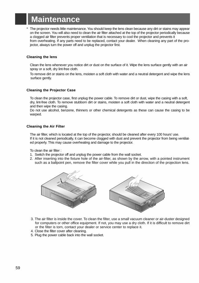
To clean the air filter :1. Switch the projector off and unplug the power cable from the wall socket.2. After inserting into the fixture hole of the air-filter, as shown by the arrow, with a pointed instrument
such as a ballpoint pen, remove the filter cover while you pull in the direction of the projection lens.
3. The air filter is inside the cover. To clean the filter, use a small vacuum cleaner or air-duster designedfor computers or other office equipment. If not, you may use a dry cloth. If it is difficult to remove dirtor the filter is torn, contact your dealer or service center to replace it.
4. Close the filter cover after cleaning.5. Plug the power cable back into the wall socket.
R
R
59

60
Memo

61
Memo
Projection LampOperating Condition
62
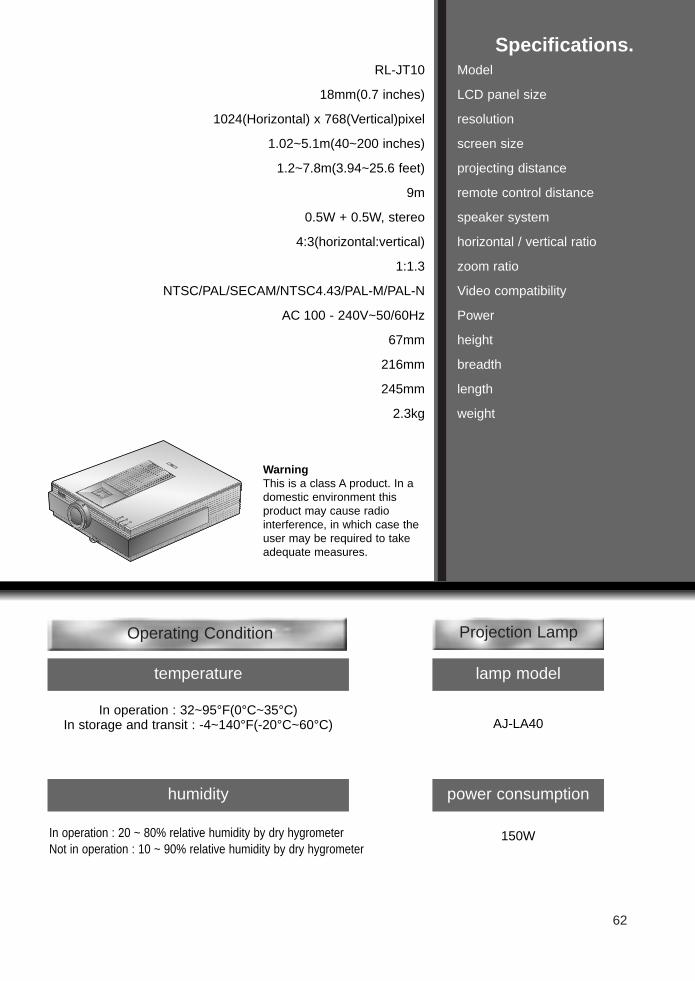
Specifications.Model
LCD panel size
resolution
screen size
projecting distance
remote control distance
speaker system
horizontal / vertical ratio
zoom ratio
Video compatibility
Power
height
breadth
length
weight
RL-JT10
18mm(0.7 inches)
1024(Horizontal) x 768(Vertical)pixel
1.02~5.1m(40~200 inches)
1.2~7.8m(3.94~25.6 feet)
9m
0.5W + 0.5W, stereo
4:3(horizontal:vertical)
1:1.3
NTSC/PAL/SECAM/NTSC4.43/PAL-M/PAL-N
AC 100 - 240V~50/60Hz
67mm
216mm
245mm
2.3kg
R
temperature lamp model
AJ-LA40
power consumption
150W
In operation : 32~95°F(0°C~35°C)In storage and transit : -4~140°F(-20°C~60°C)
humidity
In operation : 20 ~ 80% relative humidity by dry hygrometerNot in operation : 10 ~ 90% relative humidity by dry hygrometer
WarningThis is a class A product. In adomestic environment thisproduct may cause radio interference, in which case theuser may be required to takeadequate measures.