lexan* sheet - processing guide - mulford plastics · 10 sabic innovative plastics twin sheet...
TRANSCRIPT

Lexan* Sheet - Processing GuideForming, Fabricating, Finishing and DecoratingSolid un-coated and coated sheet
Specialty Film & sheet
sharing our futures

2 SABIC Innovative Plastics
ContentIndex
Pre-Drying 5Thermoforming Techniques 5Heating 7Cooling 7Drape Forming 8Pressure Forming 9Twin Sheet Forming 10Product Design 11Moulds and Mould Design 13Domes and Pyramids 14Hot Line Bending 15
Introduction 3
Forming 4
Forming 3
Contact us 28
Finishing, Decorating and Cleaning 23
Fabricating Techniques 17
Fabricating Techniques 17Drilling 18Milling 19Mechanical Fastening Devices 19Riveting Systems 21Miscellaneous Fabricating Techniques 22
Finishing, Decorating and Cleaning 23Chemical Resistance 23Painting 24Screen Printing 24Anti-static Treatment 25Adhesives and Sealants 25Cleaning Recommendations 27
SABIC Innovative Plastics 3
Introduction
FormingFrom high speed trains to street furniture, and from snowmobiles to motorway
signs, Lexan* sheet products are designed and manufactured in a diverse range
of shapes and sizes. One of the most economical methods of producing these
parts is thermoforming.
Thermoforming Lexan polycarbonate sheet is an established process that
offers the designer the freedom to develop complex shapes and forms with
cost/performance characteristics that have significant advantages over more
traditional methods of production. Low cost tooling, large part production
and reduced lead times all contribute to the advantages of producing sheet
products in this way.
With the introduction of Lexan Exell* D and Lexan Margard* FMR, thermoformed
applications can now be produced in both added value surface treated
products, providing the engineer with enhanced design opportunities.
Whilst the thermoforming process is basically very simple, the number of
different processing, production, design and finishing steps are quite varied.
To assist the designer and the converter in the selection of a suitable
production method, the following section outlines some of the techniques
used in the design and manufacture of thermoformed products in Lexan
polycarbonate sheet.
4 SABIC Innovative Plastics
MaterialVacuumforming#
Drapeforming
Twin sheetforming#
Pressureforming*
Hot/Coldline
bending**
Coldcurving
Flatlamination
Curvedlamination
Lexan 9030 / 9030 TG
Lexan ULG1003
Margard MR5E
Margard MRA3
Margard HLG5
Margard HLGA3
Margard MR5 IR
Margard FMR
Margard FLG5 XT
Exell D / Excell D TG
Exell D SC IR
Exell D ST
Sign grades
CTGXT / CTGXT AF
FR grades
Gepax
Ultem
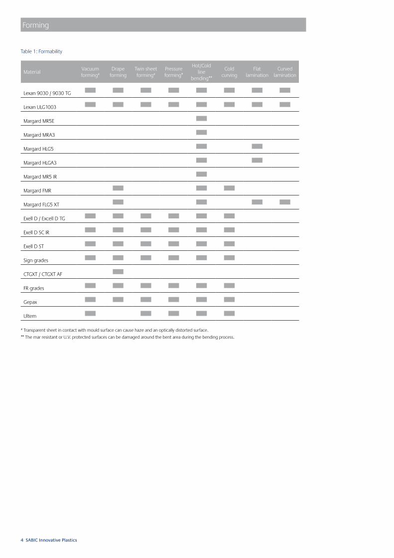
# Transparent sheet in contact with mould surface can cause haze and an optically distorted surface.
** The mar resistant or U.V. protected surfaces can be damaged around the bent area during the bending process.
Table 1: Formability
Forming

SABIC Innovative Plastics 5
Forming
Pre-dryingThe majority of thermoplastic resins, including sheet products, are hygroscopic, which means that they absorb moisture. Moisture builds up in the polymer sheet during m anufacture, transportation and storage. In the ‘as extruded’ condition it presents no problem. However, during forming, excess moisture can cause bubbling and other surface appearance problems as well as a reduction in property performance.Whilst the amount of water absorbed is not significant compared to other hygroscopic materials, it is essential that it is removed prior to forming. A hot-air circulating oven at 125°C ± 3°C is recommended. To avoid warpage, drying temperatures should not exceed 125°C and the air volume in the oven should be changed six times per hour to allow for the removal of water vapour.After removing the protective masking, the sheets should be hung vertically in the drying oven and pre-dried according to the recommendations outlined in Table 2. Alternatively, the sheets can be placed in racks with a separation of approximately 1.0 to 2.5 cm between the sheets. Following pre-drying the sheet should be processed within a few hours. The time limit depends upon the wall thickness and local environmental conditions.
Table 2: Recommended Drying Times
Sheet Thickness (mm) Drying Time (hrs)
0.375 0.15
0.50 0.25
0.75 0.50
1.00 1.00
1.50 1.50
2.00 3.00
3.00 4.00
4.00 10.00
5.00 16.00
6.00 24.00
8.00 36.00
9.50 40.00
12.00 48.00
15.00 56.00
Thermoforming TechniquesLexan* polycarbonate sheet products are easily thermoformed and a wide variety of applications can be produced using the process. The basic steps involve the heating, shaping and cooling of a thermoplastic sheet product. There are a number of different forming techniques, some of which only require heating to allow the sheet to conform to a simple positive or negative mould as in drape forming. Others, such as vacuum and pressure forming require that, after heating, the sheet is made to conform to a mould by applying pressure or a vacuum.
Whilst each process is slightly different, as illustrated in Figures 1 and 2, the basic steps are very similar. The sheet is firstly clamped along all edges inside a clamping frame. A heat source is moved over the sheet raising its temperature until it is elastic. The heat source is removed and the mould table raised. The air in the space between the sheet and the mould is evacuated and the sheet is drawn towards the mould and takes its form.Pressure can also be applied to the positive side of the mould to reproduce detailed mould features. The sheet is cooled, the mould moved downwards, and the product taken out of the machine. The clamping edges are removed from the product and, if necessary, additional machining is carried out to finish the product.
As a manufacturing process the technique offers significant advantages and is widely used for its simplicity and low production costs. However, in order to preserve its protective coatings, Lexan Margard cannot be thermoformed.
The major benefits of thermoforming are listed below:• Small to large part production• Short lead times• Small to medium size series• Flexibility

6 SABIC Innovative Plastics
Forming
Heater
Material
Vacuum Line
Product
Mould
Heater (Double Sided)
Material
Mould
Bubble Blowing
Final Forming
Plug downMould up
1
2
1. Positive Forming and Negative Forming
2. Bubble Forming and Plug-Assisted Forming

SABIC Innovative Plastics 7
13 pt praxis lightForming
3
Heating and cooling
HeatingControlled and uniform heating of Lexan polycarbonate sheet is the critical factor in the production of good quality thermoformed parts. Sandwich type heaters are recommended as they provide slow even heat on both sides of the sheet. These may be of the ceramic or quartz infra-red type. Proportional timers, together with a controlled heating rate are recommended, and due care and attention should be paid to the influence of power variations and air draughts. Slow heating rates will balance out hot spots and allow the sheet edges to reach the required forming temperature. Pre-heating of the clamping frame to 120°C-130°C is recommended. Since Lexan polycarbonate sheet cools rapidly, it is essential that final control and heating is carried out on the forming machine itself. Normal sheet temperatures are in the range of 170°C-225°C for mechanical and vacuum forming.
Clamping Frame
Heat source
Heat source
Sheet
Optimum forming conditions depend upon part design, draw ratio, sheet thickness and the forming technique employed. However, the following basic rules still apply: • Forming at low temperatures gives the best hot
strength, minimum spot thinning, and generally shorter cycle time.
• Forming at high temperatures gives the lowest internal stress levels but it increases mould shrinkage and material thickness may not be uniform.
A compromise between the two will usually produce parts with acceptable properties within a satisfactory cycle time.
CoolingCooling times are dependent upon a number of factors. These include ambient, forming and mould temperatures, mould material, cooling system, part thickness and design geometry. However, since Lexan polycarbonate has a relatively high heat distortion temperature, formed parts can be removed from the mould at around 125°C. Forced cooling air or water cooling is not recommended.
3. Sandwich Heating
8 SABIC Innovative Plastics
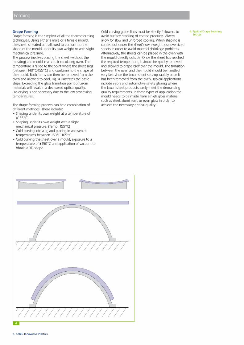
4. Typical Drape Forming Set-up
4
Drape FormingDrape forming is the simplest of all the thermoforming techniques. Using either a male or a female mould, the sheet is heated and allowed to conform to the shape of the mould under its own weight or with slight mechanical pressure. The process involves placing the sheet (without the masking) and mould in a hot-air circulating oven. The temperature is raised to the point where the sheet sags (between 140°C-155°C) and conforms to the shape of the mould. Both items can then be removed from the oven and allowed to cool. Fig. 4 illustrates the basic steps. Exceeding the glass transition point of Lexan materials will result in a decreased optical quality. Pre-drying is not necessary due to the low processing temperatures.
The drape forming process can be a combination of different methods. These include:• Shaping under its own weight at a temperature of
±155°C.• Shaping under its own weight with a slight
mechanical pressure. (Temp. 155°C) • Cold curving into a jig and placing in an oven at
temperatures between 150°C-165°C. • Cold curving the sheet over a mould, exposure to a
temperature of ±150°C and application of vacuum to obtain a 3D shape.
Forming
Cold curving guide-lines must be strictly followed, to avoid surface cracking of coated products. Always allow for slow and unforced cooling. When shaping is carried out under the sheet’s own weight, use oversized sheets in order to avoid material shrinkage problems. Alternatively, the sheets can be placed in the oven with the mould directly outside. Once the sheet has reached the required temperature, it should be quickly removed and allowed to drape itself over the mould. The transition between the oven and the mould should be handled very fast since the Lexan sheet sets-up rapidly once it has been removed from the oven. Typical applications include visors and automotive safety glazing where the Lexan sheet products easily meet the demanding quality requirements. In these types of application the mould needs to be made from a high gloss material such as steel, aluminium, or even glass in order to achieve the necessary optical quality.

SABIC Innovative Plastics 9
13 pt praxis lightForming
5. Pressure Forming
5
Pressure FormingPressure forming is basically the same as vacuum forming. However, during the final forming stage, compressed air is applied to the positive side of the mould to force the sheet to conform more closely to the mould. The result is a component with sharp features and detailed geometry. The basic steps are illustrated in Fig. 5, showing the pressure chamber mounted above the mould. Textured surfaces and small radii are typical of the fine detail which can be achieved with this process.
Pressure Chamber
Heater (Double-sided
Material
Pressure Chamber
Pressure Chamber
Bubble Blowing
Final Forming
MaximumBubble height
Mould Movingup PressureChamber down
Vacuum Applied
Air Pressure Applied
10 SABIC Innovative Plastics
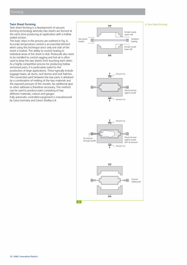
Twin Sheet FormingTwin sheet forming is a development of vacuum forming technology whereby two sheets are formed at the same time producing an application with a hollow sealed section. The basic steps in the process are outlined in Fig. 6. Accurate temperature control is an essential element when using this technique since only one side of the sheet is heated. The ability to control heating in individual areas of the sheet is vital. Photocells also need to be installed to control sagging and hot-air is often used to keep the two sheets from touching each other. As a highly competitive process for producing hollow sectioned parts, it is particularly suited to the production of large applications. These typically include luggage boxes, air ducts, roof domes and roof hatches. The connection joint between the two parts is obtained by a combination of melting of the two materials and the exposed pressure of the moulds. No additional glue or other adhesive is therefore necessary. This method can be used to produce parts consisting of two different materials, colours and gauges. Fully automatic controlled equipment is manufactured by Geiss-Germany and Canon Shelley-U.K
6. Twin Sheet Forming
Female mouldupper half
Female mouldlower half
Sheets formedagainst mould
Sheets formedagainst mouldwith air pressure
Formedhollow part
Sandwichheating
Two sheetsheated
Air pressurethrough needle
Vacuum on
Vacuum on
Vacuum on
Vacuum on
Forming
6

SABIC Innovative Plastics 11
Forming
Product DesignThe major factors that affect thermoforming product design fall into four main categories: function, economics, aesthetics and manufacturing. The first three of these are largely dependent upon the actual product. However, within the manufacturing area, certain limitations are imposed by the nature of the process. To assist the designer and the producer in the design process, the main factors affecting manufacturing are as follows.
Product GeometryThe component’s geometry determines the degree of sheet stretching which, in turn, is a function of the draw ratio. The draw ratio is the relationship between the surface area of the thermoformed product (S) and the available sheet surface inside the clamping frame (s). (See Fig. 7)
Draw ratio (QS ) = S / s
=LW + 2LH + 2WH LW
A similar relationship also exists between the sheet thickness and the average product thickness.
QT = T / T’
The above recommendations assume an even thickness distribution throughout the part, with a more or less symmetrical part geometry. If the component is long and slender, stretching may be unidirectional causing excessive thinning in certain areas. In these cases it is recommended that the depth of drawing be limited to a value equal to the smallest width of the product. For vacuum formed products, a draw ratio of 3:1 is commonly accepted as a maximum.
7. Blank Size Determination
8. Blank Size required for forming
7
8
L
W
L
W
H
T
T
Mould20˚20˚
Heated Area
Heated Area + 2 x 15 mm for clamping
Sheet Size

12 SABIC Innovative Plastics
Forming
Product RadiiIn all cases, whether positive or negative forming, all geometry changes should be accompanied by a generous radii. The basic criterion is that all radii should be at least equal to the wall thickness. General guidelines are illustrated in Fig. 9.
Draft AnglesLexan polycarbonate sheet products, in common with all thermoplastic materials, shrink upon cooling. It is therefore essential that all surfaces should be given adequate draft angles to ensure easy release of the part from the mould. For positive moulds a minimum of 2° to 3° is recommended. However, 5° to 7° is preferable when part geometry allows. For negative forming 0.5° to 1° is a recommended minimum. If, however, the mould is textured, a minimum of 2° to 3° is advised. To avoid stress build-up and difficult removal through post mould shrinkage, removal of the Lexan part should take place at a part temperature of 120°C.
UndercutsUndercuts are possible with vacuum forming. However, this often makes the moulds more complex and the processing more critical. Undercuts are more common in negative forming and the simplest method is to use a loose, removable part in the mould. A typical example is that of a rim around the circumference of the part as shown in Fig. 10. The loose part can be a ring in two or more pieces that is removed from the part once it is formed. This method of producing an undercut is labour intensive and will obviously increase the cycle time. For large series, moving parts can be installed into the mould activated by both pneumatic and hydraulic cylinders.
9. Minimum Radii Recommendations
10. Typical Undercut Design
Tmin
Tmin
Rn≥4Tmin
Rs≥10Tmin
Rp≥2TT
9
10

SABIC Innovative Plastics 13
13 pt praxis lightForming
Moulds and Mould DesignMoulds used for forming Lexanpolycarbonate sheet products are relatively inexpensive and can be made from a variety of different materials. Depending upon the number of production parts required and their quality, moulds can be made from wood, plaster of Paris, epoxy resins, metal-filled polyester or metals. Since they only need to withstand atmospheric pressure there is little wear and the flow of the plastic against the mould surface is minimal. For prototypes and small series production, wood can be used. Whilst it has significant advantages in terms of availability and ease of processing, it does have disadvantages. Wooden moulds are not dimensionally stable, particularly at high forming temperatures, and often with large mouldings the release pressure can damage the mould surface. For medium to large production runs, cold curing epoxies or acrylics, or mould materials filled with aluminium are recommended. In these cases it may be necessary to provide cooling channels in the mould to conduct away the heat build-up. It is essential for part consistency that the mould temperature is kept constant during forming.
ShrinkageTo allow for post forming shrinkage, 0.6%-0.7% should be added to all dimensions with a heated mold of 120°C.
Vacuum HolesThe evacuation of air from the mould needs to achieved as quickly as possible. However, the vacuum holes should not be so large as to leave witness marks on the product after forming. To avoid marks on the moulding, 0.5-0.75 mm diameter holes are recommended. The holes can be recessed on the underside of the mould to improve evacuation, as illustrated in Fig. 12. Fig. 13 illustrates the spacer and slot design.
11. Typical Vacuum Forming Mould
12. Vacuum Hole Recommendations
13. Slot Design Recommendations
Mould
0.3-0.5 mm
SpacingWashers
Base plate
ø 0.5-0.75 mm
11
12
13

14 SABIC Innovative Plastics
Domes and PyramidsDomes are probably the simplest applications made by the thermoforming process. The technique involves clamping the edges of the sheet and, after heating, applying gentle pressure to the underside. The sheet then stretches like an elastic membrane to form the dome. With accurate pressure control, the shape is maintained until the sheet has cooled. The basic steps in the process are illustrated in Fig. 14. Taking the process one step further, pyramids can be produced, as shown in Fig. 15. A simple wooden skeleton acts as a mould and, after applying the pressure, the mould is raised and the sheet allowed to cool on the mould. Contact with the mould is limited to the edges of the pyramid and optical quality parts can easily be produced. Recommended processing temperatures are between 170°C-180°C.
14. Free-blown Domes
15. Typical Pyramid Formation
Air Air
Final part
Air Air
Final part
Air Air
Final part
Mould
Final part
Mould
Final part
14
15
Forming

SABIC Innovative Plastics 15
Forming
Hot Line BendingHot line bending is a process involving the application of heat to the bending zone to enable thicker sheets and more acute angles to be formed. The sheet is heated locally along the line of the bend using a radiation heater, typically an electrical resistance heater. Depending upon the set-up, the sheet can be heated from one or two sides. In the case of single side heating, the sheet needs to be turned several times to achieve optimum heating. The protective masking can be left on the sheet during the hot line bending process. When the sheet has reached a temperature 155°C-165°C, the heaters are switched off and the sheet bent to the required angle. For close tolerances and/or high volume production, the use of a bending machine equipped with temperature controlled heaters on both sides is recommended. A typical set-up is illustrated in Fig. 16. Since the process involves localised heating, the expansion characteristics of the sheet are not entirely predictable. For sheet widths of up to 1m, the bend line is usually straight. For sheet widths greater than 1m however, the line of the bend is often concave with the outer edges lifting, as shown in Fig. 17. Simple jigs can be constructed to allow the sheet to cool in position which reduces the degree of distortion. In all cases it is recommended that prototype parts are produced to determine the feasibility of the bending operation.
This technique involve placing the sheet under stress. However, provided certain precautions are taken, the performance characteristics of the sheet are not substantially changed.
Cold CurvingThis technique simply involves installing a curved sheet, thereby placing a slight bending stress across the sheet. The stress levels in the curve are a function of sheet thickness and radii, and, provided they do not exceed a recommended maximum, the stress will have no influence upon the property performance. The basic criteria for the minimum radii is 100 times sheet thickness for uncoated Lexan sheet products, 175 times sheet thickness for Lexan Exell D and 300 times the sheet thickness for Lexan Margard FMR. Table 3a outlines the recommended radii for a range of sheet thicknesses.This technique is not recommended for Lexan Margard MR5E. As combinations of high stress and unfavourable chemical conditions can lead to environmental stress-cracking in the contact areas, it is essential that all materials are checked for chemical compatibility prior to installation. Curving Lexan CTG or uncoated Lexan sheet, prior to the drape forming process, may be done at radii 100 times to the sheet thickness.
11. Typical Vacuum Forming Mould
12. Vacuum Hole Recommendations
Top clampingframe pivoted
Lexan sheet
Hot wireheating element
Bottom clamping framewith cooling channels
Supportframework
16
17
Table 3a: Minimum Cold Curving Radii
Sheet Thickness (mm)
Lexan Exell DMin. Radius
(mm)
Uncoated LexanProducts Min. Rad.
(mm)
1.0 - 100
1.5 - 150
2.0 350 200
3.0 525 300
4.0 700 400
5.0 875 500
6.0 1050 600
8.0 1400 800
9.5
12
15
Table 3b: Minimum Cold Curving Radii
Sheet Thickness (mm)Lexan XT
Margard FMR5XT/FLG5XT*
2 600
3 900
4 1200
5 1500
6 1800
8 2400
#One side coated FMR5XT

16 SABIC Innovative Plastics
13 pt praxis lightForming
Cold Line BendingCold line bending is possible, since Lexan sheet products are very ductile, even at low temperatures. However, the process does involve some degree of permanent plastic deformation and the results are dependent upon sheet thickness, tooling and the angle of strain bending.A typical cold line bending operation is illustrated in Fig. 18.
Recommendations for Cold Line Bending• Use sharp tool edges.• Allow sufficient time for sheet relaxation after
bending (± 1-2 days).• Do not reduce bending angle during installation or
force the sheet into the desired position.• Bending operation should be performed quickly for
optimum results.• Textured sheets should only be bent so that the
textured surface is in compression.• Due to stress relaxation immediately following
bending, overbending is usually required to achieve the desired angle.
• Coloured sheets can show tint variations along the bend following bending.
Smooth and notch-free edges (rounded and/or 45° tapered edges) of the Lexan sheet are necessary to avoid-side cracking during bending. In order to limit the critical elastic strain, cold line bending is usually restricted to an angle of 90°. Cold line bending on FR Lexan grades is limited because of the decreased notched impact of these materials. Following bending, residual stresses will remain in the sheet and will reduce the impact strength of the material in the area along the bend. This technique should therefore be limited to less demanding applications. The mar resistant coating of Lexan Margard MR5E and FMR sheet and the U.V. protected surface of Lexan Exell D sheet may be damaged around the bent area during the bending process. For more information on any of the forming techniques please contact your local GE Plastics Structured Technical Service Centre. Cold line blending on FR grades is limited because of the decreased notch impact of the material.
Table 4: Optimal settings for Lexan sheet material
# Only cold bending in the web direction gives good result.Extrusion direction results in cracking of the material.
Thickness(mm)
Bending speed
(mm/min)
Groove width(mm)
Groove angle
(0)
Radius knife(mm)
Angle knife(0)
Penetration depth(mm)
Hold time(s)
Direction(web/extr)
Angle after bending
(0)
Angle after24h(0)
Cracks(yes/no)
4 500 16 30 1 28 10.75 4 web/extr 82.5 88.5 no
5 1000 24 30 2.5 30 18 4 web/extr 85.5 91.5 no
8 500 30 40 2.5 30 17 0 web# 84.5 90.5 no
12 1000 40 40 2.5 30 23.93 4 web# 84 90 no
15 web#
18
18. Cold Line Bending

SABIC Innovative Plastics 17
13 pt praxis light
Fabricating TechniquesFabrication can be defined as the construction, manufacture or assembly of a number of related component parts. For Lexan polycarbonate sheet products, that could involve the construction of window panels, the manufacture of a large motorway sign or the assembly of a safety shield around a piece of machinery. In one way or another each of these applications requires fabrication. The following section discusses the techniques and processes used to fabricate finished products from Lexan polycarbonate sheet and provides recommendations and advice on how to achieve the best results.
Cutting and SawingLexan polycarbonate sheet products can be cut and sawn easily and accurately using standard workshop equipment. Circular saws, band saws, jig saws and common hacksaws can all be used successfully. However, certain important guide-lines should be followed. General guide-lines are listed below with specific recommendations outlined in each cutting section.
• The sheet must always be securely clamped to avoid undesirable vibration and rough cut edges.
• All tools should be set for cutting plastics with fine toothed panel blades.
• The protective masking should be left on the sheet to prevent scratching and other surface damage.
• When finishing the edges of all Lexan sheet products should be clean and free of notches.
• If possible swarf and dust build-up should be blown away with a compressed air supply.
Circular SawsThis type of cutting operation is the most common and, whilst cutting speeds and feeds are not so critical as with other thermoplastics, it is important to follow the recommended guide-lines.• Tungsten carbide tipped saw blades are preferred
with alternative teeth bevelled at 45° on both sides to improve cutting and reduce side pressure.
• Always use a low feed to get a clean cut.• Always start cutting with the blade at full speed.• For single sheets less than 3 mm thick, bandsaws or
jig saws are preferred to circular saws.
BandsawsThese can be of the conventional vertical type or the specially developed horizontal type suitable for plastic sheet materials. In both cases it is vital that the sheet is adequately supported and clamped during the cutting operation. The saw guides should be as close to the sheet as possible to reduce blade twist and off-line cutting.
Jig Saws and HacksawsThe most important consideration with this type of cutting is support and clamping, particularly with the use of a jig saw. Blades having a tooth spacing of 2-2.5 mm are ideal with the emphasis upon low cutting feeds.
Guillotine SawCan be applied commonly on non-FR type of sheets.
Fabricating Techniques
19. Figure 19
20. Guillotine Saw
Angle of hook (roke)3˚ positive to3˚ negative
A tungsten carbide tipped saw bladesuitable for cutting Lexan sheet
Tooth spacing
Clearance angle 25˚
gulletdepth
Details of a typical saw:Diameter 400 mmTooth spacing 12 mmGullet depth 11 mmShaft speed 4000 rev/min
Circular Saw Bandsaw
Clearance Angle 20º-30º 20º-30º
Rake Angle 5-15º 0-5º
Rotation Speed 1800-2400 m/min 600-1000 m/min
Tooth Spacing 9-15 mm 1.5-4 mm
Table 5: Cutting and Sawing Recommendations
19
20

18 SABIC Innovative Plastics
DrillingStandard high speed steel twist drills or drills with an angular wedged bit can be used for drilling Lexan sheet products. Carbide-tipped drills can also be used since they retain their sharp cutting edge. The most important factor to consider when drilling Lexan sheet products is the heat generated during the actual process. In order to produce a clean, well-finished hole that is stress-free, the heat generated must be kept to an absolute minimum. By following a few basic guide-lines, clean, stress-free holes can easily be produced.
• The drill hole must be cleared frequently to prevent swarf build-up and excessive frictional heat.
• The drill must be raised from the hole frequently and cooled with compressed air.
• The sheet or product must be adequately clamped and supported to reduce vibration and ensure a correctly sized hole.
• Holes should not be drilled closer to the edge of the sheet than 1-1.5 times the diameter of the hole.
• All holes must be larger than the bolt, screw or fixing to allow for thermal expansion and contraction.
• For long production runs the use of carbide-tipped twist drills is recommended.
Drilling feeds and speeds are outlined in Table 6 with the various drill configurations in Figures 21 to 23.
21. Typical Drill Configuration
22. Drill suitable for large holes
23. Drill suitable for thin sheet
REMARK: Please consult suppliers for drilling, cutting, cooling fluids, which are recommended for polycarbonate
Chisel edge
Chiseledgeangle130˚
Cuttingedges
end view
A
B
Cuttingedgeshavingzero roke
parallel tocutting edge
parallel to surfaceto be cut
90˚
Chisel edge
Chiseledgeangle130˚
Cuttingedges
end view
A
B
Cuttingedgeshavingzero roke
parallel tocutting edge
parallel to surfaceto be cut
90˚
Recommended drill angles:
Clearance Angle A 15°Rake Angle B 0°-5°Included Tip Angle C 120°-160°Helix Angle D 30°
Roke Angle 5°
wrong right wayPoint angle
(or included angle)
21
22
Hole Diameter Speed (rev/min) Feed (mm/min)
3 1750 125
6 1500 100
9 1000 75
12 650 50
18 350 25
Table 6: Drilling Recommendations
23
?
Fabricating Techniques

SABIC Innovative Plastics 19
13 pt praxis lightFabricating Techniques
MilingLexan sheet products can be machined using conventional milling machines fitted with standard high speed knife cutting tools. Once again the importance of suitable clamping cannot be over-emphasised. Mechanical jigs and fixtures, or vacuum chucks provide a suitable clamping medium. Table 7 outlines appropriate cutting speeds and feeds with a typical cutting tool illustrated in Fig. 24. Forced-air cooling enables higher cutting rates. However, care should be taken not to over-heat the material. The use of cutting fluids to lubricate or cool the sheet is not recommended.
Computerised trimming is a fully automatic milling process. It is extremely accurate and operates horizontally as well as vertically. The use of a vacuum-operated jig avoids vibration of the part ensuring a smooth cut. Standard high speed, two-sided cutting routers with tungsten carbide tips are recommended, with a cutting speed of approximately 250 m/min at 25.000/30.000 RPM at a sheet thickness of 4 mm.
For FR grades and Ultem please consult GE Plastics Technical Center for special guidelines.
24
24. Typical Milling Cutter
Cutting edge
Clearance Angle 5º-10º
Rake Angle 0º-10º
Cutting Speed 100-500 m/min
Cutting Feed 0.1-0.5 mm/rev.
Table 7: Milling Recommendations
Mechanical Fastening DevicesWith a few exceptions, all mechanical assembly techniques involve some form of additional fastening device. The choice of device is often dependent upon the nature of the fastening required. Whilst rivets tend to be permanent, screws and nuts can be made detachable and some of the spring clips types can be either permanent or separable.There are many different types of mechanical fastening system which can be used successfully to assemble plastic sheet components. Within the limitations of this publication only a small number can be discussed.
For simplicity they are divided into three groups:• Screws, nuts and bolts• Rivets• Spring clips and other fastening devices
Two important factors need to be considered with all these fastening systems. Firstly, allowance needs to be made for thermal expansion and contraction. All holes, slots and cut-outs must be machined over-size to allow for the dimensional changes as a result of temperature changes. Secondly, the distribution of tightening torque should be equal. With the aid of compatible rubber washers and large screw and rivet heads, the tightening torque should be spread over as wide an area as possible and should not be excessive.
Material m/m ºC x 10-5
Lexan sheet 6.7
Glass 0.7 - 0.9
Aluminium 2.1 - 2.3
Steel 1.2 - 1.5
Table 8:

20 SABIC Innovative Plastics
13 pt praxis lightFabricating Techniques
25. Blind Nut andBlind Screw Anchor
26. Other Typical Fastening Systems
27. Figure 27
Machine ScrewsThe majority of these screws are made from steel, but other metals and alloys are used for specialised applications. Several examples of this type of fastening system are shown on this page. Figures 25 and 26 illustrate sheet fastening devices known as ‘blind screw’ and ‘blind nut’ anchors.
Self-Tapping ScrewsSelf-tapping screws are widely used within the plastics industry. Basically they produce their own thread as they are driven into a hole and may be considered whenever an assembly is likely to be dismantled and re-assembled. Whilst the majority of these screws are designed for
Metal washer withlaminated rubber
Oversized hole
Metal washerwithlaminatedrubber
Lexan sheet
Profiled metal
Sealing cap
The stems washer is free-spinningand preassembled to the screw.A controlled spring load is appliedto the plastic.
Metal sheet, diecast orplastic of any thickness.
The standoff of the stemswasher carries clamp load.
Available with a varietyof point styles.Available in a wide
variety of thread forms.
Threads inside washerprovide resistance tostripping in thin sheet metal.
Sheet product
Available in a variety of head styles.
26
25
27
plastic mouldings, with the aid of spring clips and washers they can be adapted for sheet applications.Fig. 27 show some typical fastening systems.
CautionIf the application calls for a screwed assembly, it is vitally important that the following recommendations are considered.• Do not use countersunk head screws as the ‘wedging’
action of the countersunk head causes excessive hoop stress on the sheet. This can lead to part failure.
• Be sure that all oil, grease and other coatings are removed from the screws before assembly. Certain oils and greases can cause environmental stress cracking.

SABIC Innovative Plastics 21
13 pt praxis lightFabricating Techniques
Riveting SystemsWhilst riveting is a popular and effective assembly technique, certain guide-lines should always be followed when considering this type of assembly method. Riveting can induce both radial and compressive stresses in the plastic sheet and precautions should be taken to distribute these forces over as wide an area as possible. In a plastic-to-plastic assembly a metal back-up washer with laminated rubber is recommended to reduce the compressive stresses. If the diameter of the rivet with a rubber washer is slightly bigger than the hole diameter, then the hoop stresses will be
28
29
Lexansheet
Compatiblerubber washer
Metal back-up washer
Back-up washerwith laminated rubber
Compatiblerubber washer
Oversized hole Metal
Plastic
Plastic
28. Rivet Assembly
29. Typical Pop-Rivet Assembly
transmitted to the washer rather than the plastic sheet. For plastic-to-metal joints, the head of the rivet with a rubber washer should be against the plastic, and the hole in the sheet should be large enough to allow for thermal movement. Holesize is 1.5 x expanded rivet diameter. Rivet diameters should be as large as possible and spacing should be between 5-10 times their diameter. SABIC Innovative Plastics recommends the use of aluminium, brass and copper rivets. There are several different types of riveting system, however, the most popular is the ‘pop-rivet’. This type of rivet provides the means to assemble two components together with access restricted to one side only. Figures 28 and 29 illustrate typical rivet assemblies.

22 SABIC Innovative Plastics
13 pt praxis lightFabricating Techniques
Miscellaneous Fabricating TechniquesMany different techniques are used to cut and fabricate Lexan polycarbonate sheet products.
These techniques include:• Shearing• Punching• Tapping• Laser Cutting• Water Jet Cutting
Whilst these techniques are used, they are not recommended since they either induce unnecessary stress on the finished part or result in a poor surface finish. With both shearing and punching the process involves a shearing action with a guillotine or a punch which tends to leave a roughly cut surface. This surface often contains micro-cracks which may lead to premature failure. Tapping is possible in Lexan polycarbonate. However, the process is usually restricted to moulded parts. Self-tapping screws or machine screws require a minimum depth to achieve the necessary holding power and sheet products do not have the necessary thickness.
Laser cutting of SABIC sheet products is not recommended due to the following disadvantages: • Rough cutting edges • Carbon deposition on cutting edges • Stress level increase in thick sheets• Discoloration
With water jet cutting, the following considerations should be taken into account: • No stress at any sheet thickness • Cutting edge requires further finishing • Limited cutting speed • Expensive equipment
For more information regarding fabricating techniques or any assembly process please contact your nearest SABIC Innovative Plastics Technical Service Centre.

SABIC Innovative Plastics 23
13 pt praxis lightFinishing, Decorating and Cleaning
Finishing, Decorating and CleaningFabrication can be defined as the construction, manufacture or assembly of a number of related component parts. For Lexan polycarbonate sheet products, that could involve the construction of window panels, the manufacture of a large motorway sign or the assembly of a safety shield around a piece of machinery. In one way or another each of these applications requires fabrication. The following section discusses the techniques and processes used to fabricate finished products from Lexan polycarbonate sheet and provides recommendations and advice on how to achieve the best results.
Chemical ResistanceThe chemical resistance of a thermoplastic is dependent upon five major factors:1. Stress level in the application2. Temperature3. Exposure time4. Chemical concentration5. Type of chemical involved
Lexan polycarbonate resin has a good chemical resistance, at room temperature, to a variety of dilute organic and inorganic acids. Water, vegetable oils, solutions of neutral salts, aliphatic hydrocarbons and alcohols are also included in this category. When a thermoplastic is attacked by a chemical it usually takes one of three forms. In the first case the chemical is absorbed into the plastic, and plasticisation and/or crystallisation occurs.The visible signs of this type of attack are swelling or surface whitening. Lexan polycarbonate is affected in this way by partial solvents such as low molecular weight aldehydes and ethers, ketones, esters, aromatic hydrocarbons and perchlorinated hydrocarbons. In addition, chemical attack ranging from partial to complete destruction of Lexan polycarbonate occurs in contact with alkalines, alkali salts, amines and high ozone concentrations. The third type of attack is often the most difficult to predict since environmental conditions dictate whether or not the plastic will be affected. Combinations of certain environments, coupled with stress and/or strain upon the material, cause stress cracking or crazing of the polycarbonate. Crazing can be induced at moderate to high stress levels by low molecular weight hydrocarbons. Products such as acetone and xylene may cause stress cracking even at very low stress levels and should therefore be avoided. Taking into account the complexity of chemical compatibility, all chemicals which come into contact with polycarbonate should be tested. For sheet products the most common contact is with sealants, gaskets and the various cleaning media. Chemical compatibility testing, table 9, is an on-going process at SABIC Innovative Plastics Structured Products and many standard products have already been tested. A complete list of recommended cleaners, gaskets and sealants is available upon request. However, a shortened list of some of the more common compounds is outlined in the respective sections in Tables 11 and 12. In case of doubt about any aspect of chemical compatibility of Lexan polycarbonate sheet always consult your nearest GE - Plastics Technical Service Centre for further advice.
Chemical Resistance of Lexan Margard MR5EThe ‘mar’ resistant coating of Lexan Margard provides an additional benefit in terms of chemical resistance. The proprietary coating is resistant to a range of chemical agents that under normal circumstances are detrimental
to Lexan polycarbonate. Table 10 outlines the results of a series of tests carried out on coated and uncoated Lexan polycarbonate sheet. The tests also included an evaluation of impact resistance and in each case the application of the chemical showed no significant effect upon the impact resistance of the Lexan Margard. The tests were conducted on 3 mm samples with an exposure time of 5 minutes, at room temperature and stress-free.
Chemical class Effects
Acids (Mineral) No effect under most conditions of concentration and temperature.
Alcohols Generally compatible.
Alkalis Acceptable at low concentration andtemperature. Higher concentrations and temperatures result in etching and attack as evidenced by decomposition.
Aliphatic Hydrocarbons Generally compatible.
Amines Surface crystallisation and chemical attack.
Aromatic Hydrocarbons Solvents and severe stress-cracking agents.
Detergents and Cleaners Mild soap solutions are compatible. Strongly alkaline ammonia materials should be avoided.
Esters Cause severe crystallisation. Partial solvents.
Fruit Juices and Soft Drinks
Compatible at low stress levels. Some concentrates not recommended.
Gasoline Not compatible at elevated temperatures and stress levels.
Greases and Oils Pure petroleum types generally compatible. Many additives used with them are not, thus materials containing additives should be tested.
Halogenated Hydrocarbons
Solvents and severe stress-cracking agents.
Ketones Cause severe crystallisation and stress-cracking. Solvents.
Silicone Oils and Greases Generally compatible up to 80°C.
Chemicals Uncoated PC Lexan Margard MR5E
Toluene W/S ok
Acetone S ok
Methylethylketone S ok
Dichloromethane W/S ok
Sulphuric acid (95-97%) ok ok
Hydrochloric acid (32%) ok ok
Ammonia (25%) ok ok
Thinner (Sikkens 1-2-3) W/S ok
Super Gasoline (Esso) W/S ok
Diesel Fuel (Esso) ok ok
Fuel C ok ok
Hairspray ok ok
Table 10: Lexan Margard Chemical Resistance Tests
Table 9: Lexan sheet chemical compatibility summary
W = surface whiteningS = surface dissolution

24 SABIC Innovative Plastics
13 pt praxis lightFinishing, Decorating and Cleaning
PaintingBe it simple or complex, decorative or functional, hand-controlled or automatic, painting Lexan sheet products offers the designer the freedom to create a dramatic effect in a sign or a simple colour code for instructions. Provided certain basic recommendations are followed, most techniques used to apply paint to wood, metal, building materials and other plastics can be used for Lexan sheet products. The important factor is once again one of compatibility. Only approved paint systems should be used. Some paint and thinner systems are not compatible with Lexan sheet products and can cause stress cracking and a reduction in impact performance. Paint systems for Lexan sheet should be flexible. Combinations of flexible primers and hard top coats could also work. Any paint system should be flexible at subzero temperatures. In view of adhesion problems, painting is not recommended for decorating the coated sides of either Lexan Margard MR5E or Lexan Margard FMR.
Painting Recommendations• Clean the sheet and remove static with a damp
chamois cloth or ionised air treatment.• Avoid too high a delivery rate and too heavy a wet
coat thickness.• Allow adequate drying before applying spray mask to
painted areas.• Do not expose painted faces to a low temperature
and high humidity environment during drying.• Use dry air in all compressed air lines. Drain water
taps frequently.• Paint solvents should be evaporated from the paint
surface as quickly as possible by providing appropriate air circulation.
• Follow recommended machining and trimming practices for finishing post-decorated faces.
For painting systems please consult technical centre.
Screen printingSilk-screen printing is a well-established process that offers a wide variety of options for a decorative finish. However, in most cases the printing must be accomplished prior to installation, since the process is basically a horizontal one and is generally restricted to small-to-medium part sizes. The process involves forcing viscous inks through a very fine, thin screen that is treated in such a way as to allow the ink only through to the patterned area. Special inks are required that are formulated so that they will pass through the mesh, while being sufficiently viscous to prevent run-out. This type of finishing operation is often used in the sign industry and a wide variety of screen printing inks and thinners are available. Once again the importance of chemical compatibility cannot be over-emphasised and only paints and thinners recommended for use with Lexan sheet products should be used. This process is not suitable for decorating Lexan Margard MR5E, Lexan Margard FMR5XT and Lexan Margard MRA3. The one side coated Margard grades such as Lexan Margard HLG5, Lexan Margard FLG5XT and Lexan Margard HLGA3 can be screenprinted at the uncoated side.
Screening Recommendations• Use only approved paints and thinners.• Do not mix different paints and inks.• Do not substitute spray thinners for screen thinners.• Do not add solvents such as toluene, xylene, cellulose
acetate, methylethylketones or other related chemicals to the inks.
• Use water-moistened chamois or soft cloths to avoid abrasion or scratching during cleaning prior to printing.
• Use the correct colour of paint to achieve opacity required.
• Provide good air circulation and ventilation during drying.
For screen printing inks please consult technical centre.

SABIC Innovative Plastics 25
13 pt praxis light
Anti-static TreatmentAs common with all insulating materials, Lexan polycarbonate sheet tends to build up a static charge. It is often necessary to clean and discharge the surface prior to painting or screen printing. Wiping the sheet with a damp chamois or applying de-ionised air to the surface is often all that is required. Another effective method in minimising static charge build-up is control of the relative humidity: the higher the relative humidity, the lower the static charge build-up will be. Relative humidity preferably should always be above 60%.
19. Internal Overglazing
20. External OverglazingAdhesives and SealantsThe use of adhesives to bond dissimilar materials is now universal. Over the past twenty years polymer technologists have developed adhesives with a wide range of properties and application profiles. Adhesion technology has become a branch of the plastics industry in its own right, offering a technique that is one of the most efficient, effective and economical methods of joining plastic components to themselves and to other materials. However, it is a technology that often causes the most problems. Whilst some adhesives/sealants form a flexible bond, others form a rigid bond. Some are capable of filling gaps, whilst others are for close contact. Some can withstand high temperatures, whilst others cannot. The choice of adhesive types is vast, as are the applications areas. It is vitally important, therefore, to select the adhesive carefully, ensuring its compatibility with the materials being used and the working environment. The importance of chemical compatibility was discussed in Section 3.1 and adhesive selection and testing is an ongoing process at GE Structured Products. A comprehensive data-base of suitable adhesives is available and in all cases it is strongly recommended that all adhesives are checked for compatibility before use. Table 11 presents an overview of some of the initial criteria used to select an adhesive and Table 12 provides a list of compatible adhesives indicating generic types, trade names and application areas. Fig. 30 outline some typical joint configurations and can be a guide in determining the right joint geometry for an application.
Adhesive Type Joins Lexan sheet to Supplier
Epoxy Metals, Plastics, rubbers 3M Company
Epoxy Plastics 3M Company
Polyurethane Plastics, Metals, wood Henkel
Polyurethane Plastics, Metals, wood Henkel
Hot Melt Plastics, Wood 3M Company
Hot Melt Plastics, Wood Glass, Ceramics Henkel
Silicone Lexan uncoated, Lexan Exell D, Lexan Margard MR5E + FMR, Building Materials Momentive Performance Materials
MS polymer Lexan uncoated, Lexan Exell D, Lexan Margard MR5E + FMR, Building Materials Bostik
Tapes Plastics, Glass, Metals 3M Company
Tapes Metals / Plastic Fasson
Tapes - Velcro
Tapes - Multifoil
Tapes - Sellotape
Table 11: Adhesive Selection Chart fot Lexan polycarbonate sheet products
Impact Behaviour Moisture Behaviour Number of Components Temperature Limits (°C) Gap Filling
Epoxy Bad Very Good 1 or 2 200 + +
Polyurethane Very Good Good 1 or 2 140 +
Hot Melt Good Good 1 60 +/-
Silicone Excellent Very good 1 or 2 250 +
Table 12: Adhesive Groups and Property Profile
The actual choice of adhesive will depend upon the design of the joint, the circumstances under which the joint will be used and the prevailing environmental conditions. In all cases the adhesive type should be fully tested under exact conditions to determine complete compatibility and performance.
Finishing, Decorating and Cleaning

26 SABIC Innovative Plastics
Lap JointsThe double butt lap joint provides maximum uniform stress distribution in the load bearing area.
The joggle lap joint allows a more uniform stress distribution than a single tapered lap joint.
A tapered single lap joint is more efficient than a single lap joint, allowing for bending of the joint edge under stress.
A double lap joint allows for greater rigidity than a single lap joint.
A simple lap joint could create cleavage and peel stress under loading, particularly in bonding thin sheets.
A round lap joint can be used to add rigidity and strength to an assembly and minimise the deflection of flat sheets.
Double scarf lap joints have better resistance to bending forces than double butt joints.
Butt JointsRounded tongue and groove joints are self-aligning and can act as an overflow reservoir for adhesives.
Landed scarf tongue and groove joints function as control stops for adhesive line thickness.
Recessed tongue and groove joints improve cleavage resistance of straight butt end joints.
Straight butt end joints are not usually recommended for most types of applications.
30. Joint Design Configurations
Finishing, Decorating and Cleaning
30
1. Double Butt Lap Joint
2. Joggle Lap Joint
3. Tapered Single Lap Joint
4. Double Lap Joint
5. Simple Lap Joint
6. Round Lap Joint
7. Double Scarf Lap Joint
1. Rounded Tongue and Groove Joint
2. Landed Scarf Tongue and Groove
3. Tongue and Groove Joint
4. Butt Joint

SABIC Innovative Plastics 27
13 pt praxis lightFinishing, Decorating and Cleaning
Cleaning RecommendationsPeriodic cleaning of all Lexan polycarbonate sheet products can be accomplished easily and without the need for specialised cleaning agents. However, as is the case with all thermoplastic materials, certain chemicals can cause structural as well surface damage and precautions need to be taken to avoid any aggressive cleaning agents. The basic cleaning agent for all Lexan polycarbonate products is a solution of lukewarm water with mild soap or household detergent, using a soft cloth or sponge to loosen any dirt and grime.All surfaces are then rinsed with cold water and dried with a soft cloth to prevent water spotting. However, in some cases this may not be sufficient and certain solvent cleaners may be needed to remove stubborn stains, graffiti etc. In these cases the following list of cleaning agents are approved for use at room temperature:• Methyl alcohol• Ethyl alcohol• Butyl alcohol• Isopropyl alcohol• White spirit• Heptane• Hexane• Petroleum ether (BP 65°)
Cleaning prior to FormingShould it be necessary to Forming to clean Lexan sheet, it is recommended that the dust is blown off with an ionising air gun or the sheet is wiped with a soft cloth dipped in water or a mixture of isopropanol and water.
Recommendations for Cleaning Lexan MargardThe unique surface of Lexan Margard sheet provides superior protection against chemical attack. Even graffiti such as spray paint are easily and quickly removed. Although Lexan Margard has a mar resistant coating, the use of abrasive cleaners and/or sharp cleaning instruments that may damage or scratch the coating should be avoided.
The recommended cleaning procedure for the removal of graffiti etc. is as follows:• Paints, marking pens, inks, lipstick, etc, use graffiti
remover.• Labels, stickers, use kerosene or white spirit.• Final wash with warm soap solution, followed by rinse
with clean water
For graffiti removers please consult Johnson Diversey.Web page: www.johnsondiversy.com
Points to remember!
• Don’t use abrasive or highly alkaline cleaners.• Never scrape the sheet with squeegees, razor
blades or other sharp instruments.• Don’t clean Lexan sheet products in the hot sun
or at elevated temperatures as this can lead to staining.

THE MATERIALS, PRODUCTS AND SERVICES OF SABIC INNOVATIVE PLASTICS HOLDING BV, ITS SUBSIDIARIES AND AFFILIATES (“SELLER”), ARE SOLD SUBJECT TO SELLER’S STANDARD CONDITIONS OF SALE, WHICH CAN BE FOUND AT http://www.sabic-ip.com AND ARE AVAILABLE UPON REQUEST. ALTHOUGH ANY INFORMATION OR RECOMMENDATION CONTAINED HEREIN IS GIVEN IN GOOD FAITH, SELLER MAKES NO WARRANTY OR GUARANTEE, EXPRESS OR IMPLIED, (i) THAT THE RESULTS DESCRIBED HEREIN WILL BE OBTAINED UNDER END-USE CONDITIONS, OR (ii) AS TO THE EFFECTIVENESS OR SAFETY OF ANY DESIGN INCORPORATING SELLER’S PRODUCTS, SERVICES OR RECOMMENDATIONS. EXCEPT AS PROVIDED IN SELLER’S STANDARD CONDITIONS OF SALE, SELLER SHALL NOT BE RESPONSIBLE FOR ANY LOSS RESULTING FROM ANY USE OF ITS PRODUCTS OR SERVICES DESCRIBED HEREIN. Each user is responsible for making its own determination as to the suitability of Seller’s products, services or recommendations for the user’s particular use through appropriate end-use testing and analysis. Nothing in any document or oral statement shall be deemed to alter or waive any provision of Seller’s Standard Conditions of Sale or this Disclaimer, unless it is specifically agreed to in a writing signed by Seller. No statement by Seller concerning a possible use of any product, service or design is intended, or should be construed, to grant any license under any patent or other intellectual property right of Seller or as a recommendation for the use of such product, service or design in a manner that infringes any patent or other intellectual property right.
SABIC Innovative Plastics is a trademark of SABIC Holding Europe B.V.* Trademark of SABIC Innovative Plastics IP B.V.
©2009 SABIC Holding Europe B.V.All Rights Reserved
www.sabic-ip.com/sfs SABIC-SFS-6212Printed in xxx
Contact us
Americas:SABIC Innovative PlasticsSpecialty Film & SheetOne Plastics AvenuePittsfield, MA 01201USAT +1 413 448 5400F +1 413 448 7506Toll Free 800-451-3147
Europe:SABIC Innovative PlasticsSpecialty Film & SheetPlasticslaan 14612 PX Bergen op ZoomThe NetherlandsT +31 164 292911F +31 164 292940
Pacific:SABIC Innovative PlasticsSpecialty Film & Sheet1266 Nanjing Road (W)16th Floor, Plaza 66200040 ShanghaiChinaT +86 21 6288 1088F +86 21 6288 0818
email: [email protected]