letco enterprises presents - macs w res... · letco enterprises presents navistar hvac systems...
TRANSCRIPT

LETCO ENTERPRISES PRESENTS
NAVISTAR HVAC SYSTEMS OVERVIEW AND
SERVICES TIPS

NAVISTAR MODELS
LONESTAR PROSTAR
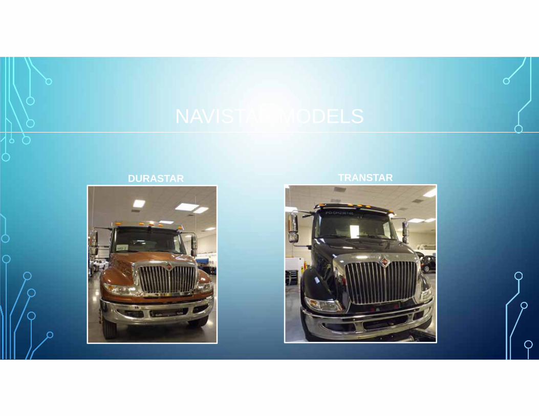
NAVISTAR MODELS
DURASTAR TRANSTAR

MULTIPLEXED ELECTRICAL SYSTEM
• Electrical devices outputs; lamps, gauges, switches – controlled by an ECU
• Use data links to send multiple signals to ECUs • System can both: a. Perform tasks, b. Monitor
components• Communication by Datalinks: decreases total
number of wires required. • By connecting switches to ECUs, the ECUs can
then share switch information on the Datalink with other ECUs.

MULTIPLEXING
• Computers talk in Binary code uses 8 Bits to make a Byte,
• 8 Bit Binary “Alphabet” 1248163264128
• Uses a base system of 2:
• 0 = low voltage: Off, Low, No
• 1= High voltage: On, High, Yes
• Example of Binary Message: 19
1 2 4 8 16 32 64 1281 1 0 0 1 0 0 0
5
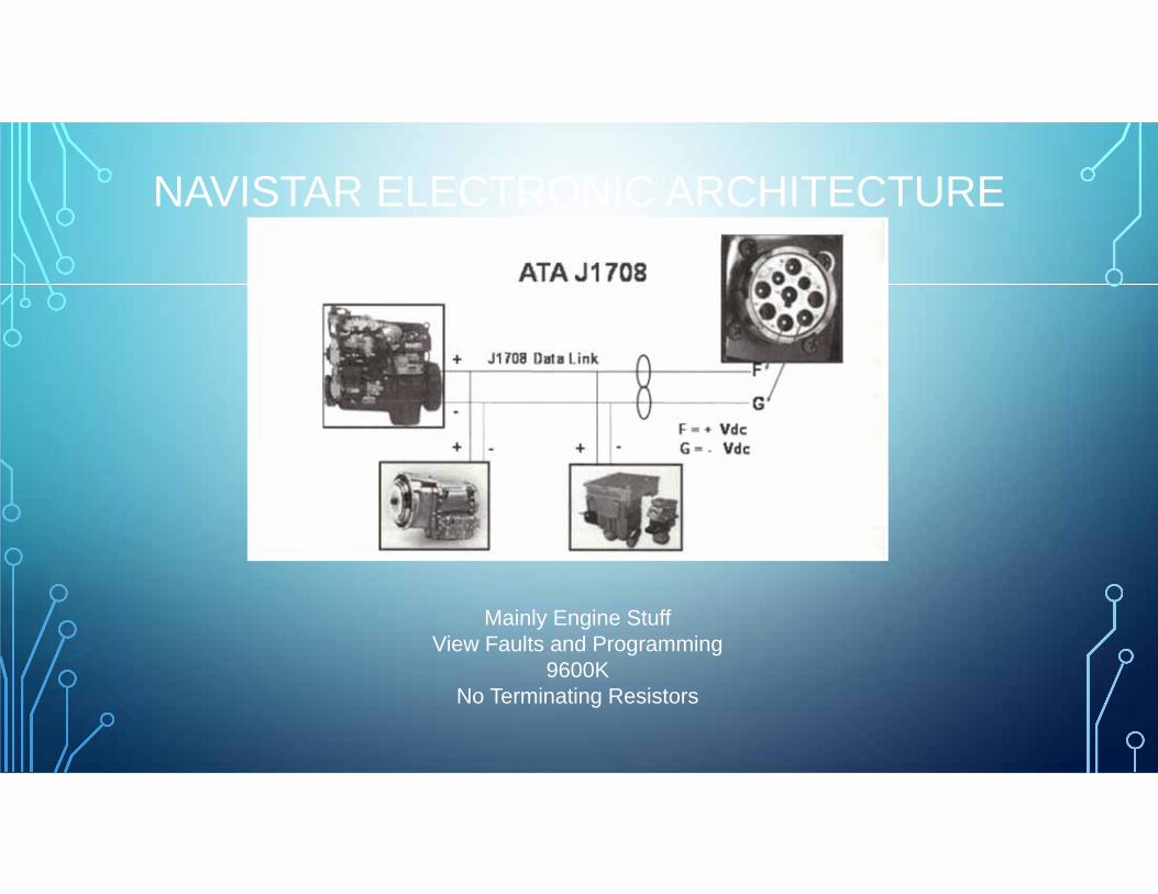
NAVISTAR ELECTRONIC ARCHITECTURE
Mainly Engine StuffView Faults and Programming
9600KNo Terminating Resistors

NAVISTAR ELECTRONIC ARCHITECTURE
J1939 Drivetrain Data Link250K
Terminating Resistors(2) 120 Ohm
1. Instrument Panel Opposite to Fuse block center2. Located on Transmission Harness
J1939 BUS ISSUES
Loss of Power, Ignition or Ground to a Module will set communication Faults.
Low Battery voltage can cause voltage shedding that may turn off a module.
Always confirm Power and Grounds and Charging System before J1939 Diagnosis.

J1939 BUS ISSUES
Open Backbone: loss of terminating resistor, loose or disconnected bus leg. DTCs will set that messages from modules below the break have not been received.
Open or Loose connection to an single module: Only the affected Module will not report. Other modules will set DTC indicating that the “dead” module messages were not received.
Short: any short to ground or short to voltage or CAN High or CAN Low shorted together will result in no communication between the modules or data line.

DSL CONNECTOR

DATA LINK CIRCUIT TESTS

NAVISTAR HVAC SYSTEMS
• CCOT 2001 thru March 2007 • TXV March 2007 and Up
Compressor
Condenser
Accumulator
Evaporator Orifice Tube
Expansion ValveExpansion Valve
CompressorCompressor
CondenserCondenserReceiver/DrierReceiver/Drier
EvaporatorEvaporator

COMMON HARDWARE
Electronic Gauge Cluster HVAC Control Head
• (RCD) Refrigerant Control and Diagnostic System
• Sets Fault Codes and turns on the CHECK A/C warning lamp.
• Control grounds A/C Request signal at Body Module
• Sends Diagnostic Signal to the Body Module.
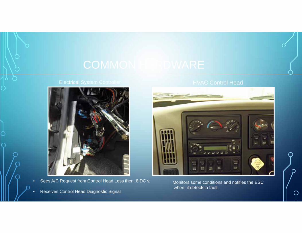
COMMON HARDWAREElectrical System Controller HVAC Control Head
• Sees A/C Request from Control Head Less then .8 DC v.
• Receives Control Head Diagnostic Signal
Monitors some conditions and notifies the ESCwhen it detects a fault.

COMMON HARDWAREBody Module ECM
• Engine RPM to Body Module via J1939 Drivetrain Data Line
• Vehicle Speed to Body Module via J1939 Drivetrain Data link.
• Aux HVAC Controls talk on the J1939 Body Data Link.
The ESC/BCM will assign a DTC’s to each faultA Fault that sets one time is stored as inactive in the EGC memory.If the fault repeats, it is Active and stored in the EGC.

COMMON HARDWARE
Engine Control Module Power Distribution Center
Controls Engine Fan SolenoidMonitors Engine RPM
Contains the Main power fuses for subsystemsFuse element may crack and cause intermittent power lose

COMMON HARDWAREPressure Transducer
Air Driven Engine Fan If Equipped
• Works like a Binary and Fan Switch in One. • Communicates on the J1939 drivetrain data Link
between the Body Module and the ECM.• Turns On 285 PSI and Higher,
Runs at one minute intervalsuntil head pressure is below 185 PSI
Fan will turn on when A/C Request signal is received and Vehicle speed is less then 10 MPH, engine speed over 1200 RPM,High Side Pressure over 100 PSI and Inlet Thermistor over 85 PSI.

PressureTransducer
ControlHead
A/CClutch
A/C CLUTCH VOLTAGE FLOW TWO THERMISTORS
A/C Request
Body ControllerModule
A/C Diagnostics
Evap Outlet Thermistor
Evap Inlet Thermistor
A/C Pressure TransducerFeedA/C Pressure Transducer Signal
A/C Compressor
A/C Pressure Transducer Thermistor Signal
InletThermistor
OutletThermistor
ZVR
FET Controlled
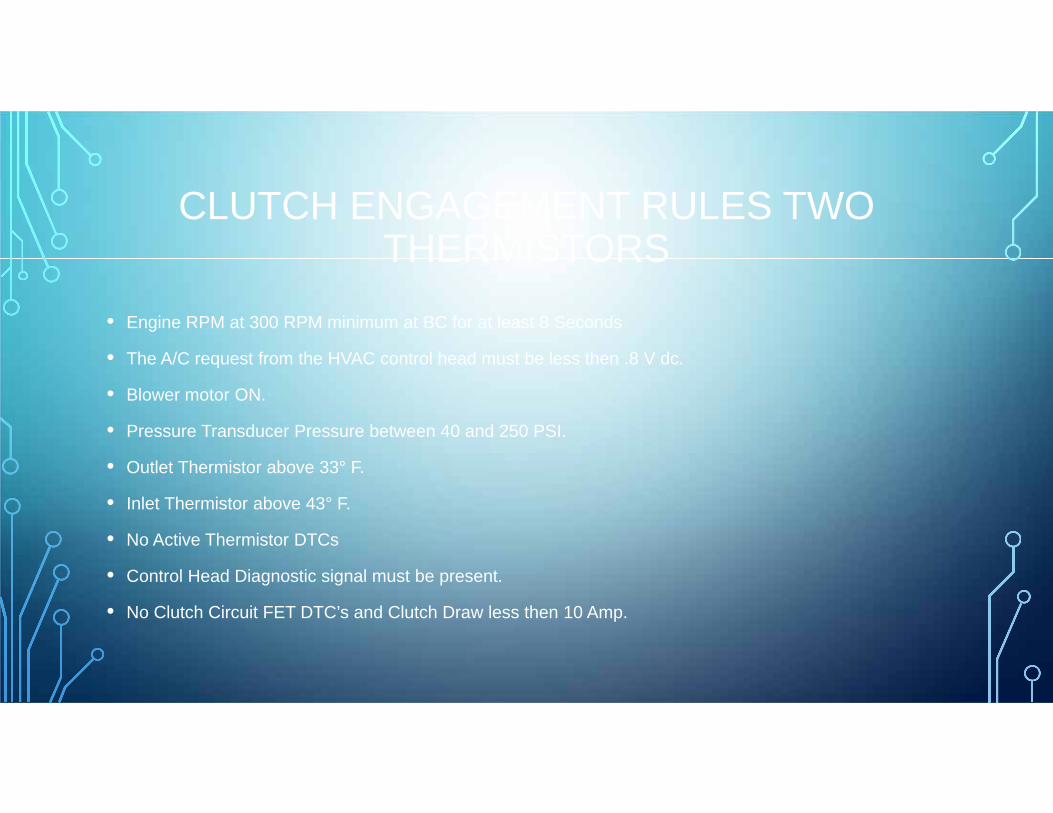
CLUTCH ENGAGEMENT RULES TWO THERMISTORS
• Engine RPM at 300 RPM minimum at BC for at least 8 Seconds
• The A/C request from the HVAC control head must be less then .8 V dc.
• Blower motor ON.
• Pressure Transducer Pressure between 40 and 250 PSI.
• Outlet Thermistor above 33° F.
• Inlet Thermistor above 43° F.
• No Active Thermistor DTCs
• Control Head Diagnostic signal must be present.
• No Clutch Circuit FET DTC’s and Clutch Draw less then 10 Amp.

TXV HARDWAREThermistors Pressure Transducer
• Inlet Thermistor: 30° F to 43°F• Outlet Thermistor: Below 24°F• Clutch on for more then 7 Seconds• Turns Off Clutch
• Less then 250 PSI Above 40 PSI.• Outlet Thermistor Above 33°F.• Turn A/C Clutch Off if high side over• 400 PSI.

THERMISTOR RESISTANCE TESTS
COMPARE READINGS WITH CHARTUSE IN INFRARED THERMOMETER AND COMPARE LINE TEMPERATURE TO GAUGE PRESSURE READING
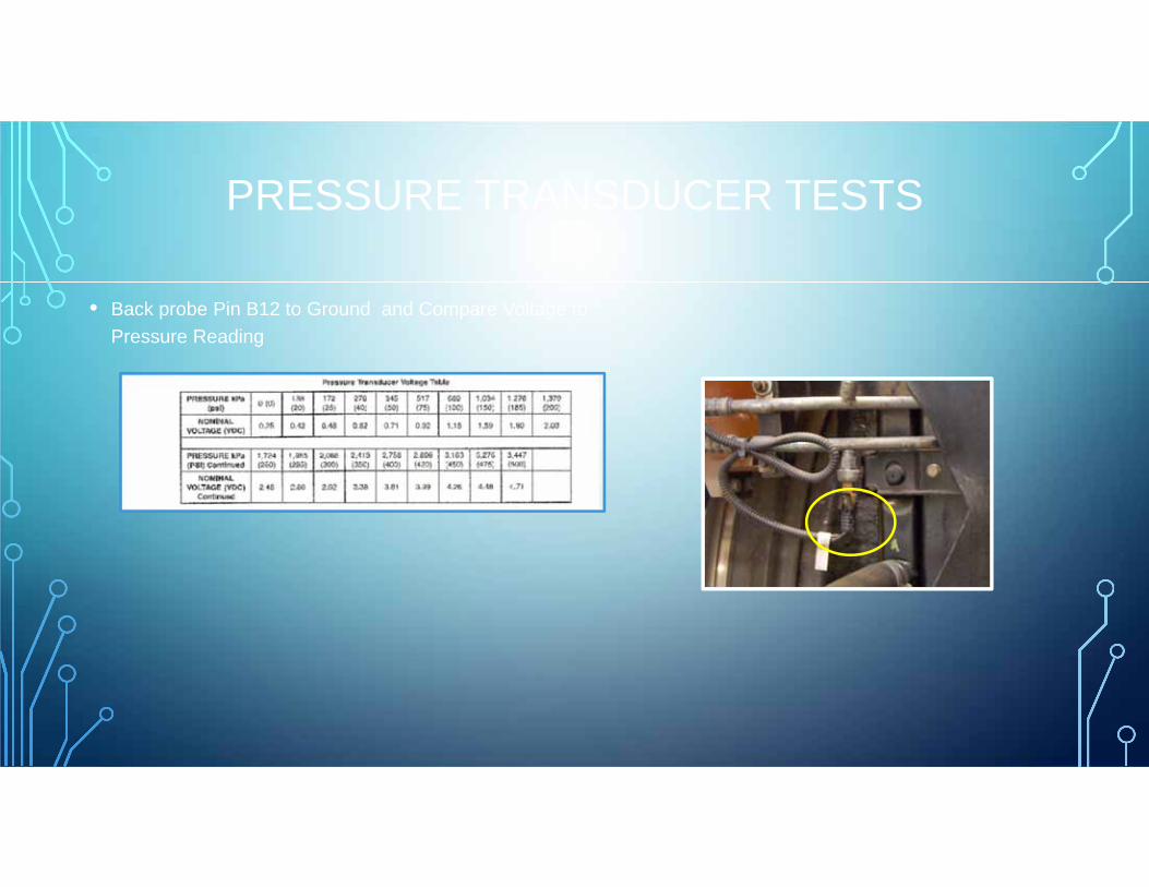
PRESSURE TRANSDUCER TESTS
• Back probe Pin B12 to Ground and Compare Voltage to Pressure Reading

PressureTransducer
ControlHead
A/CClutch
A/C CLUTCH VOLTAGE FLOW FREEZE PROBE
A/C Request
Body ControllerModule
A/C Diagnostics
Evap Outlet Thermistor
Evap Inlet PressureA/C Pressure TransducerFeedA/C Pressure Transducer Signal
A/C Compressor
A/C Pressure Transducer Thermistor Signal
Fin ProbeThermistor
ZVR
Low Pressure Switch

CLUTCH ENGAGEMENT RULES FREEZE PROBE
• Engine RPM at 300 RPM minimum at BC for at least 8 Seconds
• The A/C request from the HVAC control head must be less then .8 V dc.
• Blower motor ON.
• Pressure Transducer Pressure between 40 and 250 PSI.
• Freeze Probe Above 32°F.
• Low Pressure Switch Closed.
• No Active Thermistor DTCs
• Control Head Diagnostic signal must be present.
• No Clutch Circuit FET DTC’s and Clutch Draw less then 10 Amp.

TXV HARDWARE
Fin Probe ESC/Body Module
Be Sure to Note the Depth of the Probe Before Removal. Position New Probe to Same Depth
Electrical System Controller is the main Processor of the multiplexing system.

FIN PROBE TESTING
• Back probe connector at Plenum Inlet

TXV HARDWARE
Low Pressure Switch Pressure Transducer

TXV HARDWARE LOW PRESSURE SWITCH TESTS
• Ignition OFF
• Disconnect Switch Connector from Switch
• Check Continuity Between Pin J and K circuit complete
• Ignition ON check Pin J to Ground.
• Voltage 10 volts or Higher, if less then 10 Volts
• Check Connector B5 at ESC, If voltage is 10 Volts or Higher
• If B5 Volts OK, check connector pins for damage at ESC and Switch connector

COMMON HARDWARE
Coil Resistance: 2.2 Ohms – 4.5 OhmsMaximum Current: 2.7 AMPSClamping Diode in The Field Coil
Replacement Compressor has Full Oil Charge: 10.14 oz.Oil Type: SP-15Clutch Armature Air Gap: 0.02- 0.03 inch.

COMPRESSOR FAILURE
• Damaged Reed Valves: Caused by Flooding Evaporator Due to TXV Problems.
• Damaged Reed Valves; Caused by Liquid Charging

CLUTCH FAILURE
• Common Clutch Problems• External Oil Leaks
• Position of Snap Rings
• Clutch Hub Air Gap
• Charging System
• Voltage Drops
• Ground Circuit
• Air Flow
• Internal Restrictions

COMMON HARDWARE
Blower Motor Linear Power Module

COMMON HARDWARE
Condenser Engine Fan
Can be Flushed per IHCOil Capacity: 1.0 ouncesFitting Torque: 14-15 Ft Lbs.
Some Applications will use a Viscous Fan Clutch

COMMON HARDWARE
Inputs for A/C and Engine Fan4 wire design on late Models moved to Discharge line.TIP: Missing 5 Volt PT reference will cause Air Pressure gauges to read incorrectly!
Pressure Transducer Ambient Temperature Sensor
Range -40°F - 176°FWill display ICE at 38°FMounted by DS frame rail below door areaBehind Front License Plate bracket Late Models.

COMMON HARDWARE
Evaporator Heater Core
Vehicle May be Equipped with Shut Off Valves.Oil Capacity: 2.0 oz.Can Be FlushedC-plate Nuts: 14 – 15 Ft Lbs
COMMON HARDWARE
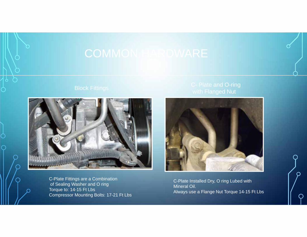
Block Fittings C- Plate and O-ringwith Flanged Nut
C-Plate Fittings are a Combinationof Sealing Washer and O ringTorque to: 14-15 Ft LbsCompressor Mounting Bolts: 17-21 Ft Lbs
C-Plate Installed Dry, O ring Lubed withMineral Oil.Always use a Flange Nut Torque 14-15 Ft Lbs

COMMON HARDWARE
Cab Filter Access ProStar Cab Filter Access DuraStar
COMMON HARDWARE
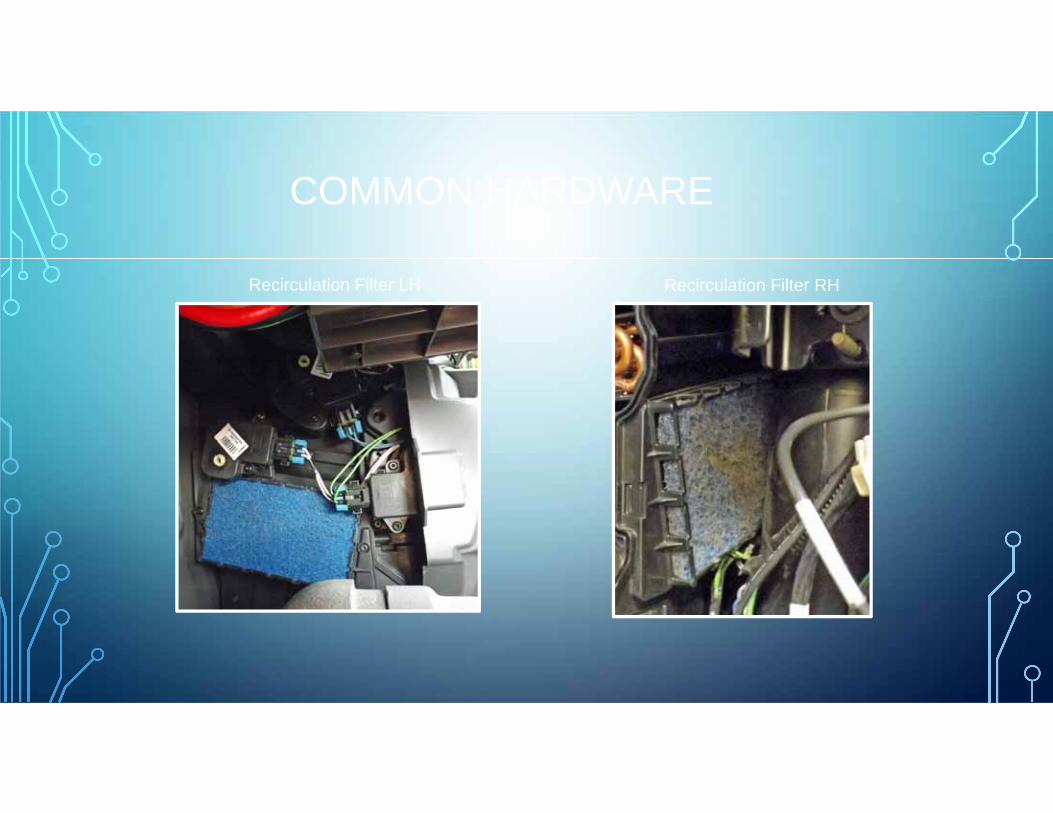
Recirculation Filter LH Recirculation Filter RH

AIR MANAGEMENT
Control Head Design and Operation Similar across all platforms

AIR MANAGEMENT COMPONENTS
Control Head connector can beDisconnected to Recal HVAC
EGC: electronic Gauge ClusterWill display A/C warning Message and DTC’s

AIR MANAGEMENT COMPONENTS
Main Fuse PanelESC: Electronic System Controller

ESC/BODY CONTROLLER
• Monitors HVAC Parameters
• Sets DTCs when parameter is out of range.
• If system damage can occur the ESC/Body Controller will disable the compressor.
• TIP: • Quick Check for Ground to BC, Done light will work with
Key On or Off. With Key Off open Door, If the Dome light does not turn on the BC may have lost its ground.
• Quick Check for Voltage, With Key On, turn on the wipers, If the wipers do not work, the BC may have lost ignition or Accessory power. If the wipers work, the BC Has correct Voltage.
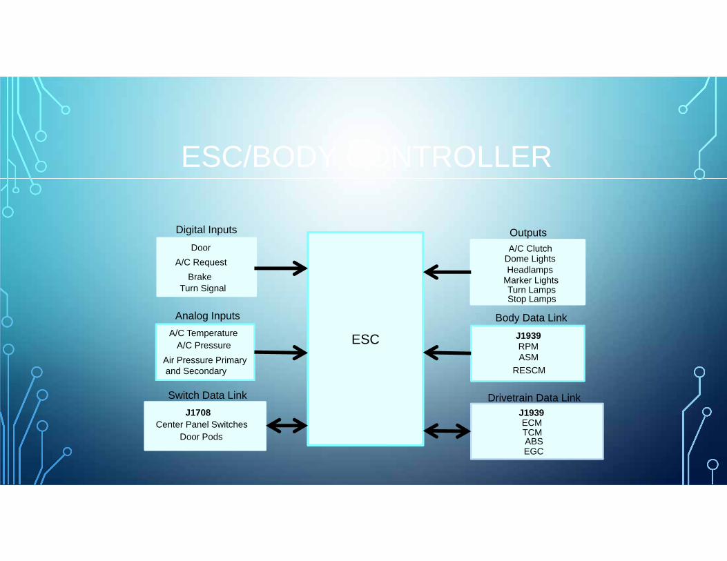
ESC/BODY CONTROLLER
ESC
Digital Inputs
Analog Inputs
Switch Data Link
Outputs
Body Data Link
Drivetrain Data Link
Door
BrakeTurn Signal
A/C TemperatureA/C Pressure
Air Pressure Primaryand Secondary
A/C Request
J1708Center Panel Switches
Door Pods
A/C ClutchDome LightsHeadlamps
Marker LightsTurn LampsStop Lamps
J1939RPMASM
RESCM
J1939ECMTCMABSEGC

BLOWER MOTOR AND LPM
Permanent Magnet Design • Linear Power Module Seven Blower Speeds,• Reads the Control Panel Output of 0 to 4.75 Volts.• The LPM acts as a variable resistor between the Blower• Motor and Ground.

BLOWER MOTOR LINEAR POWER MODULE (LPM)
Either Located on side of Evaporator Case Or on Blower Box. Either Square or Horseshoe Shaped

CONTROL HEAD TESTING
• Disconnect Connector from LPM measure voltage on the three wire connector between Pin 4 and 5.
• If Voltage readings are out of Specs, Replace Control Head.

BLOWER MOTOR TESTING
• Disconnect the two wire LPM Connection.
• Measure Voltage between the Red and Black Wire.
• If Voltage Readings Match test chart: Replace Blower Motor
• If Voltage Readings Do Not Match test chart, Replace Linear Power Module.

AIR MANAGEMENT ACTUATORS
Recirculation DoorActuator
Mode Door Actuator
Blend DoorActuator

ACTUATOR MOTOR PRECAUTIONS
• To Prevent Actuator Damage never force the drive collar into position.
• Place the door actuator in the approximate position
• Connect a 9 Volt Battery to the correct pins on the motor. Switch Battery leads to turn motor in the opposite direction.
• Rotate until the collar is aligned with the door shaft
• Torque mounting screws to: 20 inch pounds.
• Calibrate the Motor.

BLEND DOOR ACTUATOR
Blend Door Motor and Gear Train

MODE DOOR GEAR TRAIN
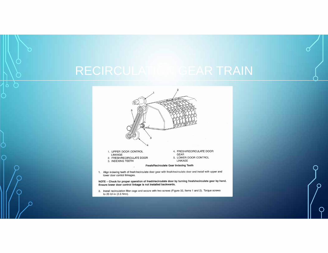
RECIRCULATION GEAR TRAIN

HVAC ACTUATOR CALIBRATION
Fuse Panel Fuse /Relay Chart
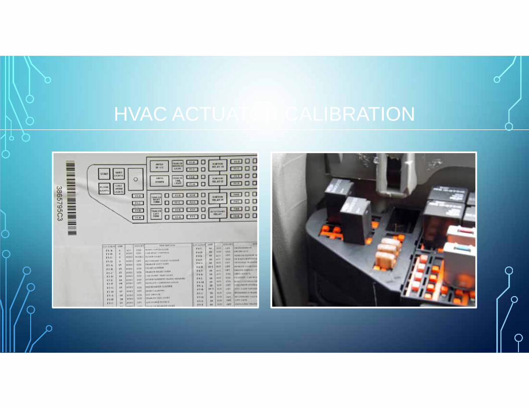
HVAC ACTUATOR CALIBRATION

ACTUATOR RECALIBRATION
• Engine Off Key On
• Blower ON
• Mode Selector to Defrost Mode
• Remove the Fuse F1-B 5 Amp HVAC Control Head
• Wait 30 Seconds and then reinstall fuse.
• Do Not operate control head and listen for door movement.
• Start Vehicle and check operation of all modes and settings.
•
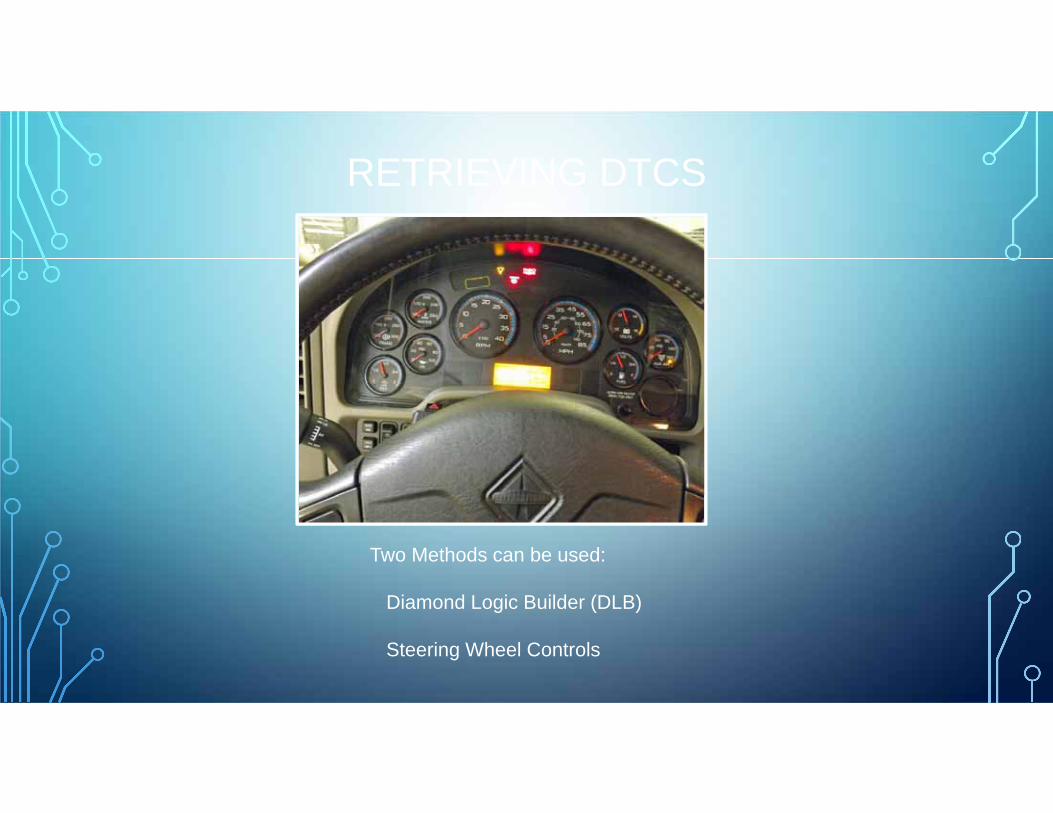
RETRIEVING DTCS
Two Methods can be used:
Diamond Logic Builder (DLB)
Steering Wheel Controls
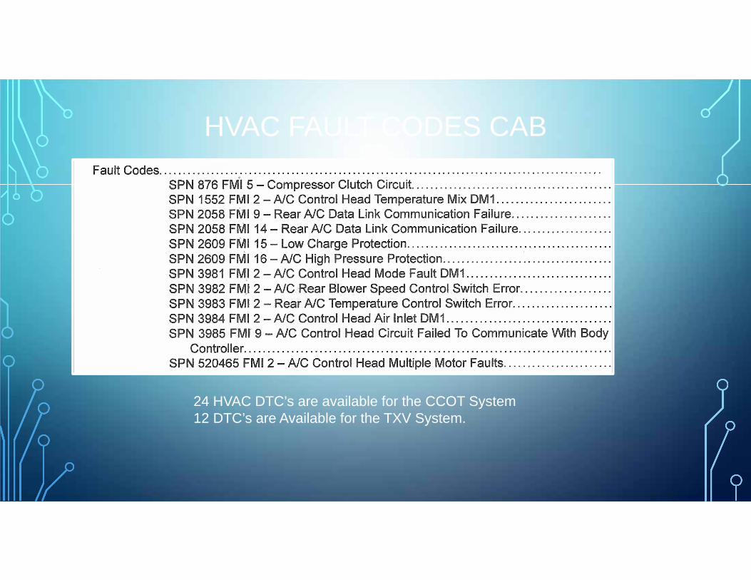
HVAC FAULT CODES CAB
24 HVAC DTC’s are available for the CCOT System12 DTC’s are Available for the TXV System.
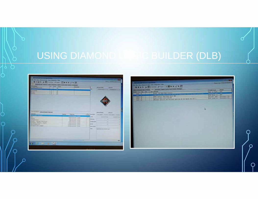
USING DIAMOND LOGIC BUILDER (DLB)

USING DLB CONTINUED

USING DLB CONTINUED

USING DLB CONTINUED

VIEWING DTC’S WITHOUT DLB
Mode/Reset ButtonLCD Readout

VIEWING DTC’S WITHOUT DLB
• Ignition On, Park Brake Set, Transmission in Neutral
• Cluster Prove Out, LCD will Display EGC Software Version
• Confirm the Park Brake Indicator is On, Press the Cruise ON and RESUME Switches at the same time.
• If no DTC’s are present the LCD will Display NO FAULTS.
• If DTC’s are present, the LCD will display the total number of active codes (A), and the previously active faults, (P).
• In about 10 seconds, the Fault codes will automatically scroll through the DTC’s pausing for about 10 seconds on each one.
• The Select/Reset button in the cluster can be used to manually scroll through the codes as well

EGC LCD READOUT

CLEARING FAULT CODES WITHOUT DLB
• To Clear Previously Active Faults Codes:
• Set Park Brake
• Ignition in ON or in Accessory
• Turn the Left Turn Signal ON and at the same time
• Press the Cruise ON and Cruise SET switches.
• The LCD should read NO FAULTS.
• Active DTC’s, Engine DTC’s and ABS DTC’s will NOT be Erased.

REFRIGERANT CAPACITIES
ProStar/LoneStar: Day Cabs: 2.5 Pounds
ProStar/LoneStar: Sleepers: 3.0 Pounds
DuraStar/WorkStar: 2.375 Pounds
TransStar/TerraStar: 2.75 Pounds
Compressor Oil Capacity ALL Models: 10.14 Ounces PAG SP 15

TXV PERFORMANCE TEST SPECS
Vehicle Setup: 1500 RPM, Open Windows, Close Doors Norm A/C High Blower, Maximum Cold

CCOT PERFORMANCE TEST SPECS
Vehicle Setup: 1500 RPM, Open Windows, Close Doors Norm A/C High Blower, Maximum Cold