lessons we learned and lessons you can learn building...
TRANSCRIPT

Gerald Coley
Lessons We Learned
and
Lessons You Can Learn
Building
BeagleBoard

Agenda
The Tail of Two Beagles
Lessons from the ABCs of Beagle
Lessons applied to Beagle-xM
Learn by building Beagle
Adapting the Beagle to suit your needs
“If you stop learning you are done.”
Dan GableWrestling Coach
Iowa Hawkeyes
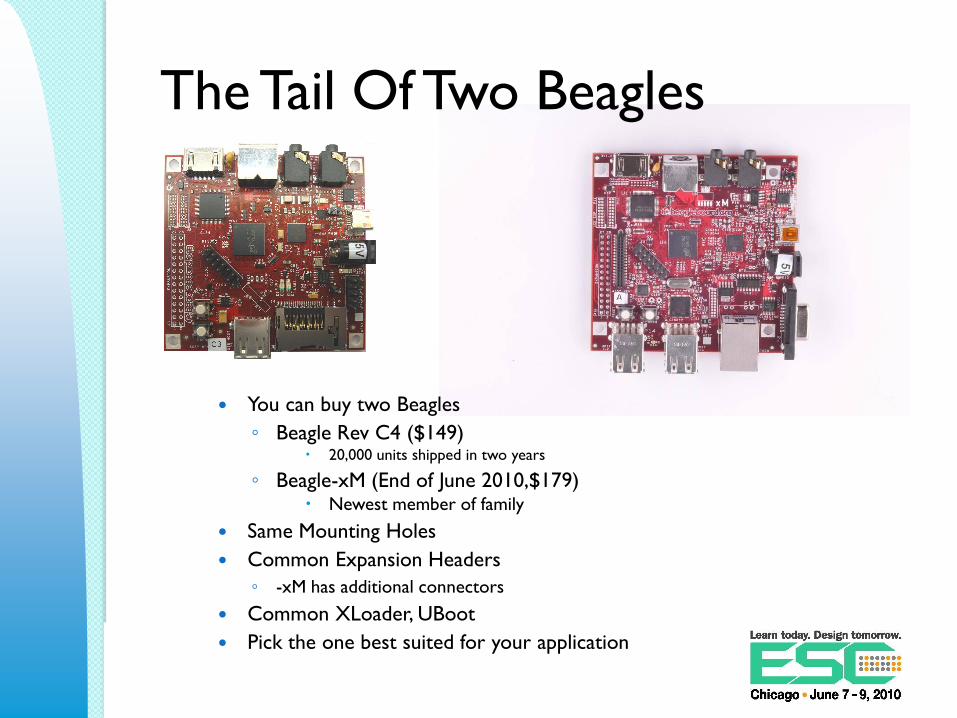
The Tail Of Two Beagles
You can buy two Beagles
◦ Beagle Rev C4 ($149) 20,000 units shipped in two years
◦ Beagle-xM (End of June 2010,$179) Newest member of family
Same Mounting Holes
Common Expansion Headers
◦ -xM has additional connectors
Common XLoader, UBoot
Pick the one best suited for your application

Beagle Rev C4
RS232 Port
DC Port
OTG Port
MMC/SD
Stereo InStereo Out
S-Video
DVI-D
HS USB
LCD
Expansion
Expansion
Port
C4
User & Reset
Current Tap

Beagle-xM
RS232 Port
DC Port
OTG Port
microSD
Stereo In
Stereo Out
S-VideoDVI-D
10/100 Ethernet
LS/FS/HS USB
Expansion Port
LCD Expansion
Current Tap
Camera
McBSP
Expansion
User &
Reset
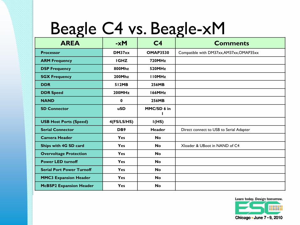
Beagle C4 vs. Beagle-xMAREA -xM C4 Comments
Processor DM37xx OMAP3530 Compatible with DM37xx,AM37xx,OMAP35xx
ARM Frequency 1GHZ 720MHz
DSP Frequency 800Mhz 520MHz
SGX Frequency 200Mhz 110MHz
DDR 512MB 256MB
DDR Speed 200MHz 166MHz
NAND 0 256MB
SD Connector uSD MMC/SD 6 in
1
USB Host Ports (Speed) 4(FS/LS/HS) 1(HS)
Serial Connector DB9 Header Direct connect to USB to Serial Adapter
Camera Header Yes No
Ships with 4G SD card Yes No Xloader & UBoot in NAND of C4
Overvoltage Protection Yes No
Power LED turnoff Yes No
Serial Port Power Turnoff Yes No
MMC3 Expansion Header Yes No
McBSP2 Expansion Header Yes No

Lessons Learned From The
ABCs of Beagle
C4

The PCB Design Challenges
OMAP35xx Package (Rev C4)
◦ .4mm Pitch
◦ Routing
TPS65950
◦ .4mm pitch PMIC
POP Implications
Limited area for connectors
◦ Location driven and not layout driven
Minimize layer count (cost)
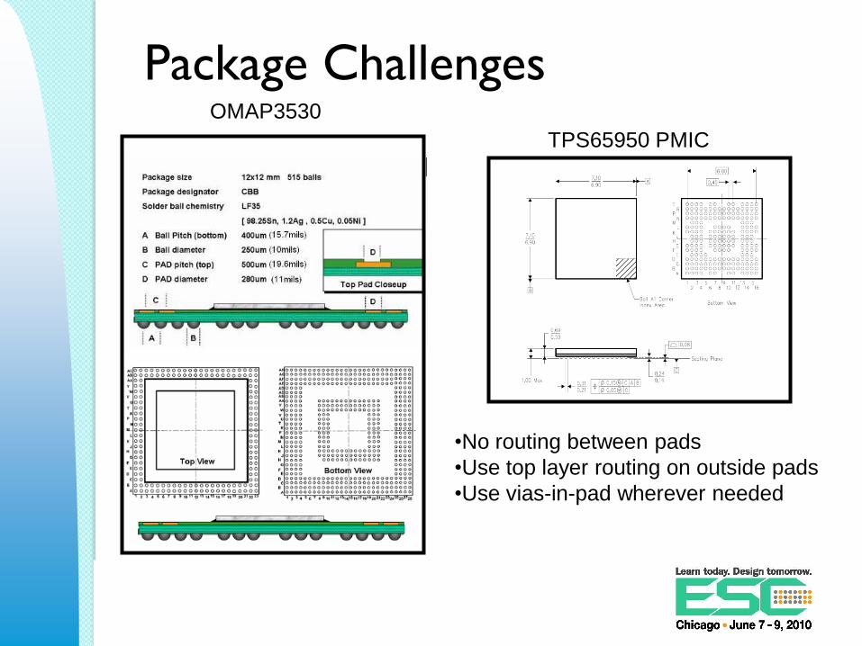
Package Challenges
TPS65950 PMIC
OMAP3530
•No routing between pads
•Use top layer routing on outside pads
•Use vias-in-pad wherever needed
PCB Fabrication Concerns
High Board cost◦ Because they can charge more
◦ Unknown = $$$$$ Does not necessarily mean the production $$ will be high
Unfamiliar with fine pitch◦ New technology for some PCB houses
Soldermask registration could be an issue
VIA technology could be a challenge◦ Lots of horror stories
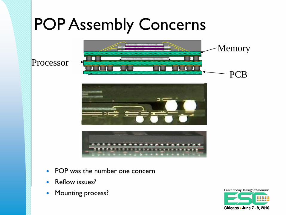
POP Assembly Concerns
POP was the number one concern
Reflow issues?
Mounting process?
Processor
Memory
PCB
Mounting .4mm Parts
Equipment can handle it
◦ Accuracy was not an issue
There could be an issue with opens
◦ Due to processor and memory contention
Not sure about lead-free
◦ High temperature requirements

Finding a CM partner
Found one, showed them POP
◦ They ran
Found a second one
◦ The were afraid, needed more equipment
Found a third one
◦ They would be happy to work us in
Finally found one
◦ No guts no glory
◦ They build Beagles today

First Pass Assembly Results Uh, where did that truck come from?
Initially had a LOT of assembly issues
◦ Shorts
◦ Tried finish, profile, solder, stencil
Tried 1 PCB Supplier twice
◦ Same bad results
Switched PCB suppliers
◦ Success!
Went back to first supplier
◦ Called in the marines and found the truck
◦ Finally success!
Found the PCB issue
◦ PCB shops do not always do what you ask
◦ Soldermask defined pads under .4mm parts
◦ Good soldermask registration and tolerance critical
Some PCB houses open up the soldermask

Soldermask TruckGOOD BAD

Beagle Assembly Process
Bottom side of board Top side of board
Reflow
Apply
Gel
Reflow
SMT
POP Memory
Hand
Assembly
Paste SMT Paste SMT Reflow

REV A Only 50 units built
Rev A...Initial Version
Rev A1…Normalized LED brightness levels
Rev A2...Changed resistor loading options for S-Video
Rev A3…Lowered pull-up values for the I2C busses
Rev A4...Lowered value of USB cap due to turn on issues
Rev A5...Incorrect inductor value on TPS65950 switchers
◦ Issues to be fixed:
DC Voltage jack
1K pull-up on wait line
Plated through hole issues
Remove 4 test points
User0 and User1 LEDS shorted

REV B Rev B1…Initial Release
◦ Fixed outstanding Rev A issues
Rev B2…USB Host not working reliably
◦ Removed from BOM and assembly
◦ Questions around the layout
Rev B3…Added a few caps back in from B2
Rev B4...Some USB HUBS not connecting on OTG Port
◦ Noise level too high…Added a capacitor onto USB power rail
Rev B5...Serial Port disconnects after a while
◦ Removed a capacitor on the 32KHZ Clock
Rev B6…PCB spin to change package of U9 and U11
◦ U9 and U11 were dying in the field
◦ BGA package could not handle the two passes
◦ Initially Rev C board layout
Issues still to be fixed:
◦ USB Host

REV C Rev C1
◦ Attempted to fix USB Host, significant improvement, still not 100%
◦ This version became the board for Rev B6
◦ Replaced U9 and U11 package
◦ Changed Revision to B1
Rev C2◦ Moved USB Host to port 2
◦ Apparent success on Port 2
◦ Added native LCD access (Community)
◦ Added PWM Signals to Expansion (Community)
Rev C3◦ The four mounting holes are now plated through and connected to ground. (Community)
◦ Additional components were added to the S-Video interface to provide a slight improvement in the overall video quality.
◦ A small Lithium battery was added to the PMIC to provide battery backup capabilities. (Community)
◦ The TWL4030 PMIC was replaced with the TPS65950.
◦ Started seeing Issues on EHCI
Rev C4◦ Switched to the OMAP3530DCBB72 device which is the 720MHZ version of the OMAP3530
◦ A more advanced fix for the EHCI noise issue on Rev C3 board. This involved a change in the power circuitry for the 1.8V rail supplied to the EHCI PHY
◦ An updated version of the UBoot software, turning on VAUX2 for the EHCI fix

Learning From RMAs
Current RMA Rate
◦ 20,000 Boards Shipped
◦ <2% Return rate
◦ 30% Were NAND Corruption by User
◦ 25% Were blown up boards (12V)
◦ 40% No trouble Found
◦ 2% Other User Abuse
◦ 2% Other issues
◦ Affective RMA rate of .04%
Top Support Issue
◦ Serial Port (Header)
User Experience Issues
Very broad User base
◦ Experienced
◦ Newbies
◦ Patient and impatient
Slow to get board running
◦ Serial port
◦ Bootable SD card
◦ Where’s my GUI?
◦ I gotta Beagle, now what?

Lessons From The ABCs
Applied to -xM
Lessons Learned Applied to -xM New Features
◦ Ethernet Port (Community)
◦ More Memory (Community)
◦ More Processing Power (Community)
◦ Native Camera Interface (Community)
◦ McBSP Audio Access (Community)
◦ Real Serial Connector (Community)
Improve User Experience
◦ Remove NAND No NAND corruption
More flexibility
Less RMAs
◦ Ship SD Card Better success out of box
◦ Power Protection Less smoke = Green
Less RMAs

Lessons Learned From -xM
TBA

Building the Beagle to Learn

Things To Know
BeagleBoard is open Source Hardware
◦ You can use the documentation
◦ We ask that you not use the beagleboard.org
logo
◦ You can adapt it for your own use
We will not sell BeagleBoards for use in
products

Key Things To Be Learned
Learn on Beagle and not your board!
PCB Layout◦ Techniques that work
◦ Ready made prototype
PCB Fabrication◦ Soldermask
◦ Via Technology
◦ Which PCB house can do it?
Assembly Experience◦ .4mm
◦ POP
◦ Is my CM up to it?
PCB Layout
Current design can be evaluated
◦ It is just one way to do it
Decide what you can use and how to
improve
CAD and Gerber data available
◦ Can be used as is
◦ Can add new stuff

PCB Fabrication
Allow the PCB house to build confidence
◦ Build an existing board
◦ Boards exist so it can be done
◦ Help to get cost out before you build your design
All information available
◦ Gerber and CAD Data
◦ Experienced PCB shops available

Circuit Board Assembly
Reduce the risks
PCB Sources◦ Those you have built
◦ Existing boards
Bill of Material provided
Work with proven data and processes◦ Board profiles
◦ Paste mask information
◦ Use those that are working
◦ Experiment with others
◦ Just a place to start
Third Party training available

Adapting the Beagle to Suit Your
Needs

Beagle Interface Connectors Main Expansion
◦ SPI, I2C, UART, McBSP
◦ MMC, GPIO
◦ Power, UART
LCD Expansion
◦ LCD signals, I2C,Power
MMC Expansion(-xM Only)
◦ MMC3,HSUSB1,ETK,GPIO
McBSP2 (-xM Only)
◦ McBSP2,GPIO
Camera Connector (-xM Only)

Adaptation Via Expansion
Adding expansion Boards
◦ Additional functions
◦ Several different ones available
◦ More coming
Create your own Expansion
◦ Add the needed circuitry

Expansion Ready
Rev C4 does not come with expansion
connectors
◦ Can be added by user
-xM does come with connectors
Mounting holes are the same
Common connectors in the same place
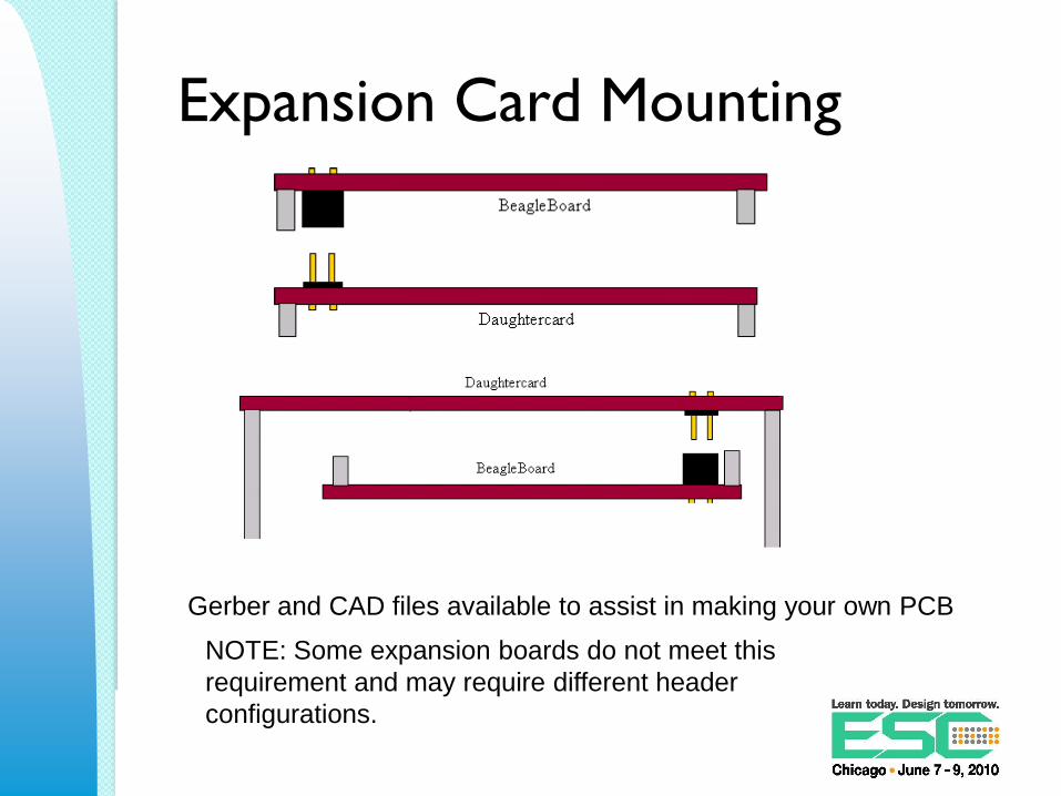
Expansion Card Mounting
Gerber and CAD files available to assist in making your own PCB
NOTE: Some expansion boards do not meet this
requirement and may require different header
configurations.

Expansion Cards & Accessories
ZIPPY ZIPPY2TRAINER VGA ADAPTER
LCD DISPLAY
PLASTIC CASE
METAL CASE
Cables & Supplies
Custom Conversion
Create a new schematic using the
OrCAD files
Take Beagle PCB files as the base
Import new netlist into PCB files
Place and route the new components
Main delta is your new components and
circuitry
Quick prototype!
Available Resources
Beagle Hardware Documentation
◦ http://beagleboard.org/hardware/design
Add-On Boards and Accessories
◦ http://www.beagleboardtoys.com/
◦ http://www.tincantools.com/home.php?cat=255
◦ https://specialcomp.com/beagleboard/index.htm
◦ http://www.esawdust.com/product/encl-dh-r1/

Questions?