lesson plan hall effect - georgia tech school of electrical …€¦ · · 2015-09-03lesson plan...
TRANSCRIPT
Lesson Plan – Hall Effect
Kenneth Patterson
Gwinnett School of Math Science & Technology Lawrenceville, GA
Georgia Institute of Technology STEP-UP Summer 2013
Subject: Physics – Electricity & Magnetism Grade: 9-11 Suggested Time: 2-3 90 minute periods Topic: Hall Effect and Hall Sensors (gaussmeters) Problem / Essential Questions:
Are the charge carriers in electric current positive or negative? How can we be sure?
How can we measure the strength of a magnetic field? Abstract: A current-carrying conductive sheet placed in a magnetic field will display the phenomenon known as the Hall Effect. This effect is a small voltage measured longitudinally across the conductive sheet. The sign of this voltage can be used to infer that the charge carriers of electric current are in fact negative particles. Students in this lesson are tasked with utilizing the Hall Effect to learn how we know that electrons are the source of electric current, not protons or some other positive particle. The lesson is a project-based learning activity where students will create their own design for a device, rather than follow a step-by-step process.

Lesson Plan – Hall Effect – Patterson
Alignment with State and Local Standards: Georgia Performance Standards SP5. Students will evaluate relationships between electrical and magnetic forces.
d. Determine the relationship between moving electric charges and magnetic fields.
SCSh4. Students will use tools and instruments for observing, measuring, and manipulating scientific equipment and materials.
a. Develop and use systematic procedures for recording and organizing information.
Gwinnett County Schools AKS D – Electricity and Magnetism
Analyze (via laboratory analysis) the properties of magnetic fields and their relationship to electric fields.
Objectives:
- To determine the sign of the charge carriers of conventional electric current. - To examine the interaction between electric current and magnetic fields. - To build a simple electronic device that senses and measures magnetic fields.
Anticipated Learner Outcomes: Students will be able to
Determine the direction of force on a moving charge or an electric current using the right-hand rule.
Prove that conventional electric current is carried by negatively charged particles. Calculate the strength of a magnetic field from Hall Voltage measurements. Express how fundamental laws and theories can be used to create sensors and
measurement devices. Background:
One of the most confusing and non-intuitive concepts when students are learning about electric circuits is the definition of conventional current. Every student learns that current flows from positive terminals to negative terminals, and this is the standard convention for positive current. This convention persists despite the fact that in an electric circuit the negatively charged electrons flow opposite to the direction of current. Calculations in electrostatics and electromagnetism are not upended by this seeming contradiction because current is defined as change in charge over change in time:
I = ΔQ/Δt
Lesson Plan – Hall Effect – Patterson
The ΔQ term depends on the sign of the charge. Because of this, a flow of negative particles moving in a direction of negative current is mathematically equivalent to a flow of positive particles moving in a direction of positive current (Students may find this easier as “a negative times a negative makes a positive”). Mathematically there is no way to determine if the charge carriers of electric current are positively or negatively charged.
The naming convention of “positive and negative charge” was established in the late 1700s by Benjamin Franklin. Franklin’s experiments involved rubbing wool onto wax and observing the static interactions. He assumed that an object could either have a surplus or a deficiency of charge, rather than assuming that there are in fact two kinds of charge. Franklin also assumed that charge would flow from the smooth wax to the rough wool, based on texture alone. Because this direction was backwards, he incorrectly named the deficiency of charge as “positive” and the surplus as “negative.” However, as we have seen, this convention is mathematically equivalent to its opposite, and thus the precedent was continued as scientists began to study electricity in earnest. The idea of two separate charge carriers was not needed until much later when the interaction between electricity and magnetism was discovered.
In the 1800s, Ampere and Oerstead discovered that a current carrying wire is affected by a magnetic field. Students are generally introduced to this idea as a force on a moving charged particle in a magnetic field, expressed as:
F = Qv x B This is equivalent to magnetic force experienced on a current carrying wire:
F = Il x B The direction of the resultant force will always be perpendicular to both the magnetic field and the initial motion of the particle, essentially accelerating it sideways. The sign of the charge Q is vitally important to determining the direction of force a particle experiences. A negatively charged particle moving the same direction in the same field as a positively charged particle will experience a force in the opposite direction. Students require significant practice evaluating cross products using the right-hand rule to properly understand the directions the magnetic force will point. In 1879, Edwin Hall hypothesized that if a magnetic field exerts force on moving charged particles, the moving charged particles that constitute an electric current should also experience the same force. His experimental setup involved measuring a voltage across a narrow conductive strip that was carrying a current, shown below.

Lesson Plan – Hall Effect – Patterson
Note that this is not a complete circuit schematic. In the figure above B is the direction of the field everywhere, I is the direction of current through the solid conducting sheet, and V is simply a voltmeter connected perpendicular to the direction of current. The voltmeter measures what is known as the Hall voltage. Under zero magnetic field and high current the Hall voltage will be zero because the moving charges are not deflected towards the meter’s terminals. However, under a strong magnetic field and strong current, the charge carriers will be deflected in such a way that they build up on one side of the solid conducting sheet.
In the figure above we have assumed that the charge carriers are negative electrons moving opposite the direction of I. Note that due to F = Qv x B the negatively charged particles will be deflected upwards towards the voltmeter’s cathode. This will give a negative Hall voltage reading! Note that if we had assumed that the charge carriers were positive protons moving in the same direction as I we would read a positive voltage. This negative voltage is the measurement that Edwin Hall made in his experiment. This result is the evidence that proves electric current is carried by negative particles moving opposite to I. Furthermore, the Hall voltage can be calculated using the following:
VH = IB/nqt

Lesson Plan – Hall Effect – Patterson
where I is the current, B is the magnetic field in Teslas, n is the charge carrier density of the material, q is the fundamental charge, and t is the thickness of the material. For most metals, there will be a single charge carrier per atom, and n can be calculated using the molar mass and the density of the material. Materials – At least one per group of:
9V Batteries and Battery pack OR other DC power source Wires and alligator clips Electrical tape Aluminum foil Multimeter Neodymium magnets OR other strong magnetic field source
o Safety concern: Strong magnets can injure fingers or skin. Plan: Expected Student Background Knowledge – Students should already be familiar with electric current, electric circuits, and
F = Qv x B. This project is designed to take place at the end of a unit on electricity and magnetism.
1. Students will begin the lesson with the two essential questions. Ask students to think
about ways we could “see” or detect the directions of electrons. (5 mins)
2. Lecture component should begin with history of electric charge from Ben Frankin to Edwin Hall. (5 mins)
3. Introduce the Hall effect circuit diagram shown above. Talk about the direction of current with students. Make it clear that the current will be flowing through a flat sheet and not a linear wire. Use a physical sheet of aluminum foil if necessary. Point out that the Hall Voltage measurement is made perpendicular to the direction of current. (15 mins)
4. Split the class into two halves. One half will consider the case of positive charge carriers traveling the same direction of current. One half will consider the case of negative charge carriers traveling the opposite direction of current. Ask each group where the charges will pool on each side of the conducting sheet. If the charges pool in such a way and our voltmeter is aligned in such a way, will the voltage we measure be positive or negative? The groups will then compare their conclusions. This activity could also be done in groups of two as a think-pair-share. (10 mins)

Lesson Plan – Hall Effect – Patterson
5. If computers are available, have the students participate in an interactive Hall effect demo at http://www.magnet.fsu.edu/education/tutorials/java/halleffect/ . This demo uses an electron beam instead of an electric current. (10 mins)
6. Students will now work on Assessment I, the attached problem set, either in-class or as homework. Students may work in groups or alone. (15+ mins)
7. The capstone activity for this lesson is the project-based learning activity outlined in the Hall Effect Sensor Project Handout (attached). Students will work in small groups. This activity is designed for at least one full day of in-class work. (90 mins)
8. Set a dedicated time for students to demonstrate their working device to the instructor. Students should be able to measure a small Hall voltage with their finished device, and this voltage should switch sign when the current direction or magnet direction is switched.
Assessment: Assessment I Assessment I is a classwork or homework worksheet (see appendix). This is given so that students will be comfortable with the calculation before the project itself. Assessment II Assessment II is a project-based learning activity. Students will work in small groups to build their own Hall effect sensor device. The handout for students is attached in the appendix. Summary: This lesson is designed to be a hands-on project based student design experience. Students learn about the specific phenomenon of the Hall voltage of an electric current in a magnetic field, and then will use that to design their own electronic circuit device. The lesson incorporates engineering design process principles as well as theoretical physics knowledge. The lesson objectives are assessed using a short problem set as well as the final student project device and design.

Lesson Plan – Hall Effect – Patterson
References Hall Effect. http://hyperphysics.phy-astr.gsu.edu/hbase/magnetic/hall.html. 12 June 2013. Hall Effect Tutorial. National High Magnetic Field Laboratory. University of Florida.
http://www.magnet.fsu.edu/education/tutorials/java/halleffect/. 22 June 2013. Serway, Raymond. Beichner, Robert. Physics for Scientists and Engineers. 5th ed. Saunders
College Publishing: Fort Worth. 2000.
Tanenbaum, Andrew S. Conventional versus Electron Flow. http://www.allaboutcircuits.com/vol_1/chpt_1/7.html. 19 June 2013.

Lesson Plan – Hall Effect – Patterson
APPENDIX
I. Hall Effect Problem Set
II. Hall Effect Sensor Project Handout
III. Selected PowerPoint Slides

Lesson Plan – Hall Effect – Patterson
Name________________________________ Date___________ Period_______ 1. A rectangular copper strip has 8.49x1028 electrons per cubic meter. The strip is 0.10cm thick and carries a current of 5.0 A. Find the hall voltage if the strip is placed in a 1.2 T magnetic field. 2. A student wants to build an aluminum strip to observe the Hall Effect, but she does not know the charge carrier density, n, for aluminum. Assuming that aluminum has one free electron per atom, how many free electrons are there in 1 mol of aluminum? If the density of aluminum is 2.7x10⁻⁶ g/m3 what is the density of free electrons, n, in aluminum? 3. In an experiment designed to measure the Earth’s magnetic field using the Hall effect, a copper bar 0.500 cm thick is positioned along an east – west direction. If a current of 8.00 A in the conductor results in a Hall voltage of 5.10 pV (that’s picovolts!), what is the magnitude of the Earth’s magnetic field? (Assume that n = 8.48x1028 electrons/m3.)

Lesson Plan – Hall Effect – Patterson
Hall Effect Sensor Project INTRODUCTION
The Hall Effect is crucial to proving that the electron is the thing doing the “moving” in an electric current. It can be used to detect and measure the strength of a magnetic field. In the electronics industry these are called Hall sensors or gaussmeters (1 Gauss is equal to 0.0001 Teslas, a 1 Tesla magnetic field is a huge magnetic field!) For a thin conducting sheet inside of a magnetic field, the Hall Voltage will be:
V = IB/nqt
where I is the current in amps, B is the magnetic field in Teslas, n is the charge carrier density of the conductor, q is the charge of an electron, and t is the thickness of the material. For aluminum foil: n = 6.02x10^28 t = 0.016 mm
TASK(S)
Using your knowledge of electric circuits, magnetic fields, and the Hall Effect: Design and build a device to measure the Hall voltage when placed near a magnet Calculate the strength of the magnet based on your voltage measurement Determine the direction the magnetic field is facing Prove that the charge carriers of electric current are negative particles moving opposite the
direction of conventional current.
ACTIVITY/PROCESS
1. In your engineering notebook, design and draw a schematic circuit diagram for a prototype
device. (Remember: pay special attention to the positive and negative terminals of the voltmeter,
direction of the voltage matters!) 2. Build the prototype device. 3. Test the prototype and record the results in your notebook. Were you able to measure a voltage?
Why or why not do you think this is the case? 4. What improvements can you make to your design? Return to your prototype and make revisions
as necessary. 5. Measure and record the Hall Voltage. 6. Using the voltage you measured, calculate the strength of the magnet in Teslas. 7. What proof do you have that the charge carriers are negative? Keep very good track of the
direction of the current, the north pole of the magnet, and the direction of the voltage!
Lesson Plan – Hall Effect – Patterson
Hall Effect Sensor Project MATERIALS
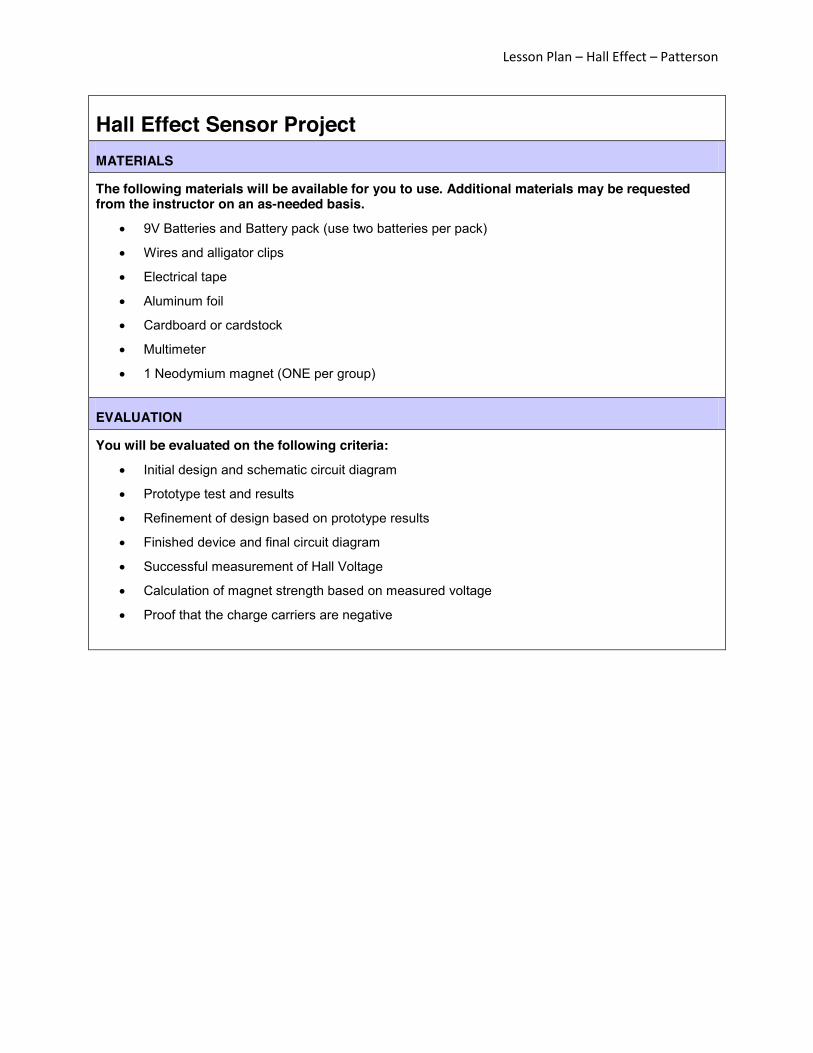
The following materials will be available for you to use. Additional materials may be requested from the instructor on an as-needed basis.
9V Batteries and Battery pack (use two batteries per pack)
Wires and alligator clips
Electrical tape
Aluminum foil
Cardboard or cardstock
Multimeter
1 Neodymium magnet (ONE per group)
EVALUATION
You will be evaluated on the following criteria:
Initial design and schematic circuit diagram
Prototype test and results
Refinement of design based on prototype results
Finished device and final circuit diagram
Successful measurement of Hall Voltage
Calculation of magnet strength based on measured voltage
Proof that the charge carriers are negative

Which of these is correct? What’s really going on physically and how do we know?

Ben Franklin set precedent for “positive” and “negative” charge.

Fortunately, either one is equivalent for
I = Q/t
And positive charge carriers are quite common! (Just not in electrical circuits)

Force on a moving charge in a magnetic field
F = qv x B
1789, Edwin Hall hypothesizes that moving charges in a current will experience this force. This motion of charge can be measured in voltage. The Hall Effect!


Hall Effect can be quantitatively described by
VH = IB/nqt I = current B = Magnetic field n = charge carrier density q = charge of charge carrier t = thickness of material

Using your knowledge of circuits and the Hall Effect, design and build a device that will detect and measure a magnetic field

9V Batteries and Battery pack OR other DC power source
Wires and alligator clips Electrical tape Aluminum foil Multimeter Neodymium magnets OR other strong
magnetic field source (At least 1 T) Safety concern: Strong magnets can injure fingers
and skin.

For Aluminum: n = 6.02 x 10^28 t = .016 mm
In a magnetic field of 1 T and current of 1 A this
results in Hall Voltage of 6.5 mV.
