lesson 7 - profexprofex.doebelin.org/wp-content/uploads/2016/09/lesson-7.pdf · lesson 7...
TRANSCRIPT

Lesson 7
“How-To” Session
Nicola Döbelin
RMS Foundation, Bettlach, Switzerland
October 03 – 05, 2016, Maastricht, NL

Refinement Strategy: Words of Wisdom
2
Release parameters one by one.
When the fit doesn’t improve anymore,
don’t try to extract more information.
Always refining everything
may lead to good fits,
but the results may be useless.
Chose your refinement strategy wisely.
Ask yourself if the results make
physical sense.

Examples
3
Example 1: Texture, preferred orientation
Example 2: Anisotropic crystallite sizes
Example 3: Non-existent phases
Example 4: Micro-absorption and Brindley correction
Example 5: Amorphous Content

Texture, Preferred Orientation
4
Images: L. Galea, RMS Foundation
Platelets lying flat
Needles, Fibers, Whiskers lying flat
may point in one direction (bundles)
Random orientation Preferred orientation

Texture, Preferred Orientation
5
Smooth, but non-continuous
diffraction rings
Some orientations are
over-represented,
others are under-represented.

Texture: Symmetrized Spherical Harmonics
6
Järvinen, M. Materials Science Forum [278-281], 1998, 184-199.
In structure files (*.str) change:
PARAM=GEWICHT=0.1_0
to
GEWICHT=SPHARn (n=0, 2, 4, 6, 8, 10)
No preferred orientation:
PARAM=GEWICHT=0.1_0
GEWICHT=SPHAR0
GEWICHT=SPHAR2
GEWICHT=SPHAR4
GEWICHT=SPHAR6
GEWICHT=SPHAR8
GEWICHT=SPHAR10

Example 1 - Texture
7
PARAM=GEWICHT=0.1_0
GEWICHT=SPHAR0
Instrument: pw1800-fds
Phases: Corundum, Fluorite
RP=4 PARAM=k1=0_0^1 PARAM=k2=0_0 PARAM=B1=0_0^0.03 PARAM=GEWICHT=0.1_0 // Both phases:
GEWICHT=SPHAR2

Example 1 - Texture
8
GEWICHT=SPHAR4
Instrument: pw1800-fds
Phases: Corundum, Fluorite
RP=4 PARAM=k1=0_0^1 PARAM=k2=0_0 PARAM=B1=0_0^0.03 GEWICHT=SPHAR4 // Both phases:
GEWICHT=SPHAR6
GEWICHT=SPHAR8
GEWICHT=SPHAR10

Example 1 - Texture
9
!
Automatic refinement strategy of BGMN
prevented over-interpretation!
Reduction depends on phase abundance and
quality of diffraction pattern.

Example 1 - Texture
10
Recommendation:
- Use a moderate order of SPHAR polynomes in your
structure files (e.g. SPHAR4)
- Let BGMN reduce the order if necessary
- Only increase the order if the fit really improves
- Refining «GEWICHT» with symmetrized spherical harmonics
functions allows to model texture / preferred orientation.
- Complexity of the polynome can be set in structure file (SPHARn).
- High order introduce large number of refined parameters.
( slow refinement, may get unstable)
- Automatic refinement strategy will protect from over-interpretation.

Anisotropic Crystallite Sizes
11
Images: L. Galea, RMS Foundation
Platelets Needles, Fibers, Whiskers
Small size
Strong peak broadening
Large size
Weak peak broadening

Example 2 – Anisotropic Crystallite Size
12
Wide peaks Sharp peak
(002) (004)

Example 2 – Anisotropic Crystallite Size
13
Change:
RP=4 k1=0 PARAM=k2=0_0 PARAM=B1=0_0^0.1 GEWICHT=SPHAR6 //
To:
RP=4 k1=0 k2=ANISO4 B1=ANISO^0.1 GEWICHT=SPHAR6 //
Use right mouse button or change manually

Example 2 – Anisotropic Crystallite Size
14
Needle length: 35.4 nm
Diameter: 11.18 nm
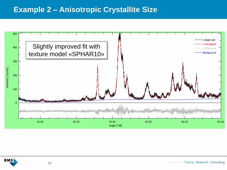
Example 2 – Anisotropic Crystallite Size
15
Slightly improved fit with
texture model «SPHAR10»

Example 2 – Anisotropic Crystallite Size
16
Automatic refinement strategy sometimes
reduces anisotropic parameters to isotropy

Example 2 – Anisotropic Crystallite Size
17
Recommendation:
- Do not refine micro-strain anisotropically unless it improves the fit
- Refine peak broadening anisotropically (B1=ANISO^0.01),
let BGMN handle the reduction to isotropy
- Check if the upper limit of B1 was reached. If yes:
- increase the limit…
- … or see next example (non-existent phases)
Refine anisotropic crystallite sizes with «B1=ANISO»
Refine anisotropic micro-strain with «k2=ANISO4»

Example 3 – Non-existent Phases
18
Experimental design:
Step 1:
- α-TCP prepared at 1350 °C
- Traces of β-TCP may have formed during cooling
Step 2:
- α-TCP hydrated to Hydroxylapatite
- β-TCP (if present) remains
Question:
- Is β-TCP present after setting?
Background Information:
- If β-TCP is present, it has formed at ~1000°C
- Must be highly crystalline with large crystallites

Example 3 – Non-existent Phases
19
Main Phase: Hydroxyapatite
Question: Does it contain β-TCP?

Example 3 – Non-existent Phases
20
Background curve goes wild
No distinct diffraction peaks from β-TCP
23.8 wt-% betaTCP (totally wrong!)
Example 3 – Non-existent Phases
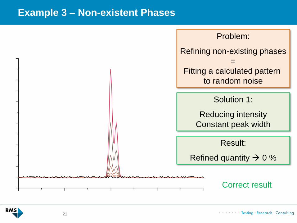
21
Problem:
Refining non-existing phases
=
Fitting a calculated pattern
to random noise
Solution 1:
Reducing intensity
Constant peak width
Result:
Refined quantity 0 %
Correct result

Example 3 – Non-existent Phases
22
Solution 2:
Increase peak width
Result:
Crystallite Size 0 nm
Over-estimated quantity
Problem:
Refining non-existing phases
=
Fitting a calculated pattern
to random noise
Wrong result

Example 3 – Non-existent Phases
23
Even worse:
No anchor points for
background anymore
Background is
poorly/randomly defined
Massive over-estimation
of non-existing phase
Result:
Totally wrong!
Unpredictable!

Example 3 – Non-existent Phases
24
GrainSize(1,1,1) = 2.47+-0.44

Example 3 – Non-existent Phases
25
Solutions:
- Use a reasonable upper limit for B1 (peak broadening, crystallite size)
- Don’t trust very small crystallite sizes (e.g. < 20 nm)
- Repeat the refinement without the questionable phase
(Does the fit really look worse? Or just as good?)
- Use additional information:
- Sintered samples: very small crystallites are unlikely
- Cement samples: very small crystallites are reasonable

Example 3 – Non-existent Phases
26
1. Edit betaTCP.str
2. Change
PARAM=B1=0_0
to
PARAM=B1=0_0^0.005
3. Run Refinement…

Example 3 – Non-existent Phases
27
< 1 % vs. 23.8 %!

Example 3 – Non-existent Phases
28
Upper limit B1 Crystallite Size β-TCP Quantity β-TCP
None 2 nm 23.8 wt-%
0.1 4 nm 14.6 wt-%
0.05 8 nm 7.0 wt-%
0.01 42 nm 0.4 wt-%
0.005 85 nm 0.8 wt-%
0.001 424 nm 0.2 wt-%
0.0005 849 nm 0.2 wt-%
0 ∞ 0.2 wt-%
How to choose the upper limit for B1?
Sample was sintered at 1350°C:
Crystallites of several
100 nm diameter expected
Any other useful data available?
Other samples which do
contain β-TCP?
Before cement reaction?
Educated Guess!

Micro-absorption and Brindley Correction
29
Weak attenuation by phase 2
Large volume of interaction
Strong attenuation by phase 1
Large particles absorb significant
part of the radiation.
Small volume of interaction
Phase quantification biased for phase 2!

Micro-absorption and Brindley Correction
30
Micro-absorption can be corrected,
but mean particle* size must be known.
*not crystallite size
0 50 100 150 200 250
0
1
2
3
4
5
Vo
lum
en
[%
]
Diameter [um]

Example 4 – Micro-Absorption
31
Reference mixture:
33.33 wt-% Corundum (Al2O3)
33.33 wt-% Fluorite (CaF2)
33.33 wt-% Griceite (LiF)
Wrong phase
quantities

Example 4 – Micro-Absorption
32
Add mean particle diameter (µm) to structure files:
Corundum: 12 µm
Fluorite: 10 µm
LiF: 9 µm
my (µ) = mass absorption coefficient
(calculated automatically by BGMN)

Example 4 – Micro-Absorption
33

Example 4 – Micro-Absorption
34
Micro-Absorption and Brindley correction:
- Try to avoid the problem in the first place (keep particle
size close to 1 µm)
- Additional information (particle size from SEM, PSD analysis)
required for all refined phases!
- Large particles still lead to grainy diffraction patterns. Brindley-
correction does not solve this problem!
Example 5 – Amorphous Content
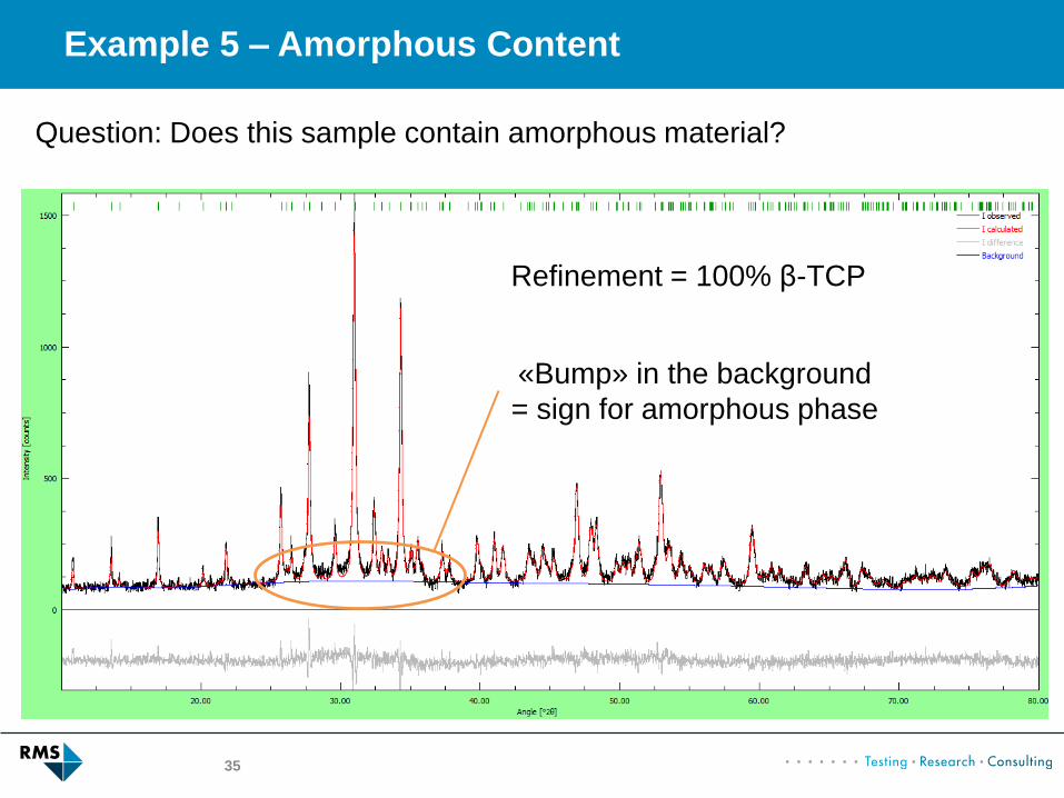
35
Question: Does this sample contain amorphous material?
Refinement = 100% β-TCP
«Bump» in the background
= sign for amorphous phase

Example 5 – Amorphous Content
36
Problem: Amorphous phases
- Don’t procude a distinct diffraction pattern
- Create a broad bump around 30° 2θ
10 15 20 25 30 35 40 45 50 55
Inte
nsity (
a.u
.)
Diffraction Angle (°2)
Most common solution:
Internal Standard
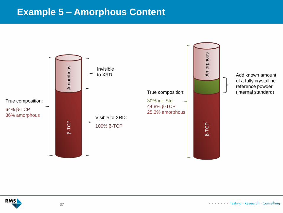
Example 5 – Amorphous Content
Am
orp
hous
β-T
CP
True composition:
64% β-TCP
36% amorphous Visible to XRD:
100% β-TCP
Invisible
to XRD Am
orp
hous
β-T
CP
True composition:
30% int. Std.
44.8% β-TCP
25.2% amorphous
37
Add known amount
of a fully crystalline
reference powder
(internal standard)

Example 5 – Amorphous Content
Am
orp
hous
β-T
CP
True composition:
30% standard
44.8% β-TCP
25.2% amorphous
38
Visible to XRD
Std
β-T
CP
Visible to XRD:
59.9% β-TCP
40.1% int. Std.
(=100%)
Std

Example 5 – Amorphous Content
39
Phase Mixed Refined Normalized to
int. Std. Normalized w/o int. Std.
Amorphous ? - Fill up to 100% =
25.2 wt-% 36 wt-%
β-TCP ? 59.9 wt-% 59.9 * 0.748 =
44.8 wt-% 64 wt-%
Internal Standard
30.0 wt-% 40.1 wt-% 40.1 * 0.748 =
30.0 wt-% -
Σ = 70.0 wt-%
0 wt-%
100 wt-%
30 wt-%

Example 5 – Amorphous Content
40
Example 5 File 2
Sample β-TCP + amorphous phase
70 wt-%
Internal Standard Monetite 30 wt-%

Example 5 – Amorphous Content
41
Example 5 – Amorphous Content
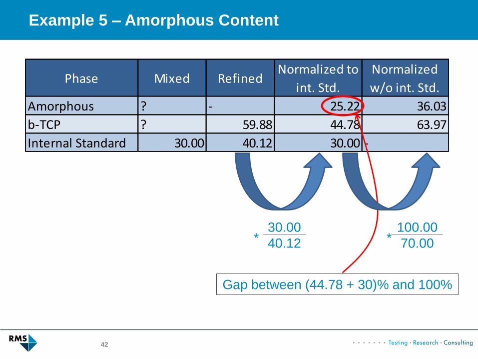
42
Phase Mixed RefinedNormalized to
int. Std.
Normalized
w/o int. Std.
Amorphous ? - 25.22 36.03
b-TCP ? 59.88 44.78 63.97
Internal Standard 30.00 40.12 30.00 -
30.00
40.12 *
Gap between (44.78 + 30)% and 100%
100.00
70.00 *

Example 5 – Amorphous Content
43
Challenge: Selection of internal standard material:
- Must be 100% crystalline
- Simple structure (cubic)
- No texture or micro-absorption problems
- Absorption coefficient similar to matrix
- Absolutely homogeneous mixing
- Must not react with sample matrix
Common materials:
- Si
- Al2O3
- LiF
Monetite was a bad choice:
- Triclinic
- Large crystals (micro-absorption)
- Severe texture effects