legged robot using hydro-muscles · legged robot using hydro-muscles ... 2.3 biomimicry and...
TRANSCRIPT
1
Legged Robot Using Hydro-Muscles
A Major Qualifying Project Report
Submitted to the Faculty of the
Worcester Polytechnic Institute
In Partial Fulfillment of the Requirements for the
Degree of Bachelor of Science
By:
Daniel Patrick Coffey
Peter Starek
Advisors: Marko Popovic (PH, BME, RBE) and Cagdas Onal (ME, RBE)
2
Table of Contents
Abstract...................................................................................................................................... 4
Acknowledgements .................................................................................................................... 5
Chapter 1: Introduction ............................................................................................................... 6
Chapter 2: Background .............................................................................................................. 7
2.1 Previous MQP .............................................................................................................. 7
2.2 Hydro-Muscles as an Actuator for Legged Robots ....................................................... 8
2.3 Biomimicry and Inspiration from Nature ....................................................................... 8
2.4 Existing Bipedal Robots ..............................................................................................10
2.4.1 Festo BionicKangaroo ..........................................................................................10
2.5 Advantages of Bipedal System for Hydro-Muscles ......................................................11
Chapter 3: Project Objectives ....................................................................................................12
3.1 Determination of Design Specifications .......................................................................12
3.1.1 Size and Weight ...................................................................................................13
3.1.2 Cost .....................................................................................................................13
3.1.3 Actuation ..............................................................................................................13
3.1.4 Locomotion ..........................................................................................................14
3.1.5 Reconfigurability ..................................................................................................14
3.1.6 Future Platform for Hydro-Muscles ......................................................................15
3.2 Project Scope and Limitations .....................................................................................16
Chapter 4: Design and Construction .........................................................................................17
4.1 Reconfigurable Construction System ..........................................................................17
4.1.1 80/20™ ................................................................................................................17
4.2 Skeleton Design ..........................................................................................................19
4.3 Modelling and Simulation ............................................................................................20
4.4 Hydro-Muscles as Actuators .......................................................................................23
4.4.1 Power Augmentation ............................................................................................23
4.4.2 Compliance of Hydro-Muscles to External Forces ................................................26
4.5 Fabrication of Hydro-Muscles .....................................................................................27
4.5.1 Elastomeric Tube .................................................................................................27
4.5.2 Sheathing ............................................................................................................27
4.5.3 Barbed Fittings and Hose Clamps ........................................................................28
3
4.6 Parallel Operation .......................................................................................................29
4.7 Flow ............................................................................................................................30
4.8 Electrical System and Control Circuitry .......................................................................31
4.8.1 Power Supply (Batteries) .....................................................................................31
4.8.2 Control Circuit ......................................................................................................32
4.8.3 Microcontroller .....................................................................................................32
4.8.4 Software System ..................................................................................................32
4.9 Final Construction .......................................................................................................34
Chapter 5: Iterative Testing and Results ...................................................................................37
Methodology for Experimentation ..........................................................................................37
5.1 First Test .....................................................................................................................37
5.1.1 Setup ...................................................................................................................37
5.1.2 Response ............................................................................................................38
5.2 Second Test................................................................................................................39
5.2.1 Setup ...................................................................................................................39
5.2.2 Response ............................................................................................................40
5.3 Third Test ...................................................................................................................41
5.3.1 Setup ...................................................................................................................41
5.3.2 Response ............................................................................................................42
5.4 Cambridge Science Festival .......................................................................................43
Chapter 6: Conclusions .............................................................................................................44
6.1 Actuation and Locomotion ...........................................................................................44
6.2 Reconfigurable Test Platform ......................................................................................44
6.3 Future Work and Recommendations ...........................................................................45
Chapter 7: References ..............................................................................................................46
Appendix ...................................................................................................................................47
Example of code: ...................................................................................................................47
4
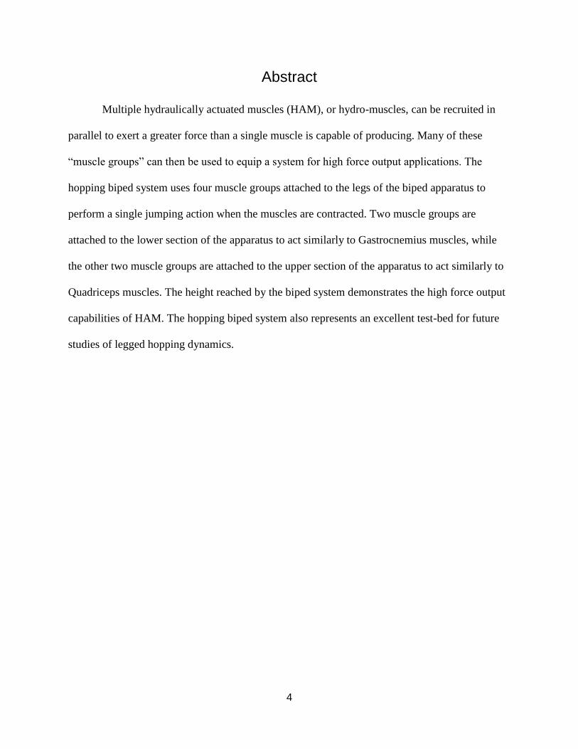
Abstract
Multiple hydraulically actuated muscles (HAM), or hydro-muscles, can be recruited in
parallel to exert a greater force than a single muscle is capable of producing. Many of these
“muscle groups” can then be used to equip a system for high force output applications. The
hopping biped system uses four muscle groups attached to the legs of the biped apparatus to
perform a single jumping action when the muscles are contracted. Two muscle groups are
attached to the lower section of the apparatus to act similarly to Gastrocnemius muscles, while
the other two muscle groups are attached to the upper section of the apparatus to act similarly to
Quadriceps muscles. The height reached by the biped system demonstrates the high force output
capabilities of HAM. The hopping biped system also represents an excellent test-bed for future
studies of legged hopping dynamics.

5
Acknowledgements
We would like to thank our advisor, Professor Marko Popovic, for the countless hours he
spent guiding us through this project and holding us to such a high standard. We would also like
to thank our co-advisor, Professor Cagdas Onal, for the advice and critique he provided us.
The team also would like to thank the graduate students Nicholas Deisadze and Saivimal
Sridar for their inexhaustible assistance in every step of constructing and testing the robot, as
well as Roger Steele for allowing use of the machine shop.
6
Chapter 1: Introduction
The purpose of this project is to demonstrate the high force output applications of
hydraulically actuated muscles through constructing a bipedal hopping robot. The bipedal
hopping robot is designed to serve as a test-bed for high force output applications of the muscles.
Other goals of this project include a high jumping performance, a biologically inspired design,
and a modular robotic construction to allow quick alterations of the design. Presented here is the
process of design, construction, and experimentation of a bipedal hopping robot equipped with
hydro-muscles.
Recent years have brought tremendous technological advancements to the field of
robotics. Wheeled robots have long been a standard among mobile robotics researchers for their
simplicity, but the emerging field of legged robotics may stand to revolutionize the industry.
Legged robots’ advantage over wheeled robots regards how they approach mobility; while
wheeled robots may be much easier to design and may operate faster than legged robots at this
time, wheeled robots are limited to traversing flat floors and ramps. Performing human like
actions such as climbing stairs, navigating over obstacles, or traversing rough and uneven terrain
is beyond the scope of wheeled robotics, but not legged robotics.
The proceeding report extends the work done last year by the Hydro Artificial Muscle
Exo-Musculature project, where hydraulically actuated muscles were first developed and tested
[1]. Documented in this report are the efforts undertaken by a team of two senior undergraduate
students at Worcester Polytechnic Institute to utilize the technology of hydro-muscles within the
applications of legged robotics, and to test their capabilities in producing large forces.
7
Chapter 2: Background
2.1 Previous MQP
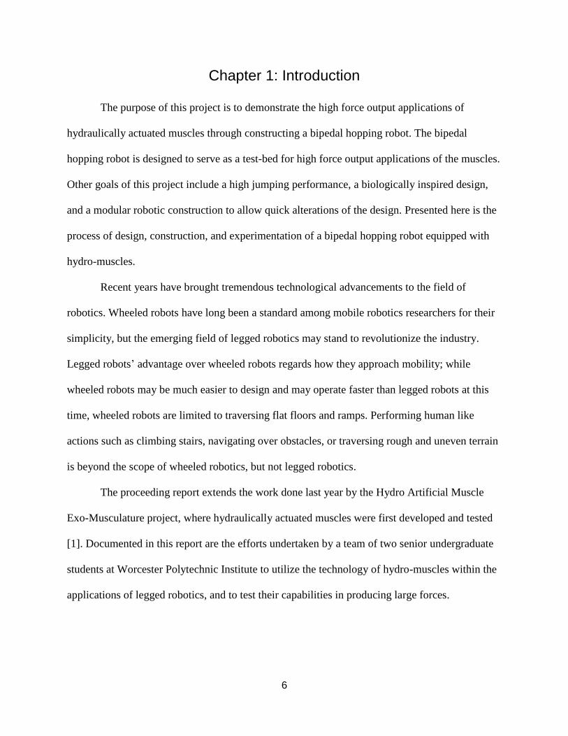
Hydro-muscles were invented by Dr. Marko Popovic at Popovic Labs in 2013 [1]. At this
time, hydro-muscles were operated under low pressures (below 80 psi) for proof-of-concept
applications to showcase the new technology. During the same year, Dr. Marko Popovic advised
a project team that installed three of these hydro-muscles onto a model skeleton arm to exhibit
the capabilities of the muscles [1]. A photo of this model can be seen in the following figure:
Figure 1: Model skeleton arm equipped with hydro-muscles to exhibit their capabilities.
The robot developed and discussed in this report necessitated further development of
hydro-muscle technology. Hydro-muscles that are capable of withstanding significantly larger
pressures and producing substantially more power than their predecessors were produced. The
advancements made by this team in hydro-muscle technology to meet these requirements are
detailed in chapter 4.
8
2.2 Hydro-Muscles as an Actuator for Legged Robots
Hydro-muscles are a new and developing technology, and may be innovative with many
applications in the robotics field. A hydro-muscle is at its simplest, an elastic tube that expands
linearly when pressurized with some working fluid. To prevent the elastic tube from expanding
radially, the tubing is enclosed within a crumpled fabric sheath that is fixed to both ends of the
tubing. Upon pressurization, potential energy is stored in the stretched elastic, which can quickly
be transformed into kinetic energy upon releasing the pressure [1].
2.3 Biomimicry and Inspiration from Nature
In order for earthbound animals to move, they must overcome the force of gravity. While
moving, animals typically minimize the amount of work they exert to maximize efficiency in
their mobility. In order to jump, terrestrial animals must produce enough power to lift their
weight into the air. This power is typically generated by muscles in the hips and legs of terrestrial
animals [2].
In legged robotics, an iterative approach to design is desirable for improving efficiency
and solving complex kinematic problems [2]. In a sense, this approach is similar to evolution’s
role in biological designs. Legged robots are inherently inspired by biological designs, and are
typically modelled after bipeds and quadrupeds. Due to nature’s success in solving complex
kinematic problems through designing various efficient bipedal creatures, it was decided to base
the design of this project using inspiration from natural biological systems.
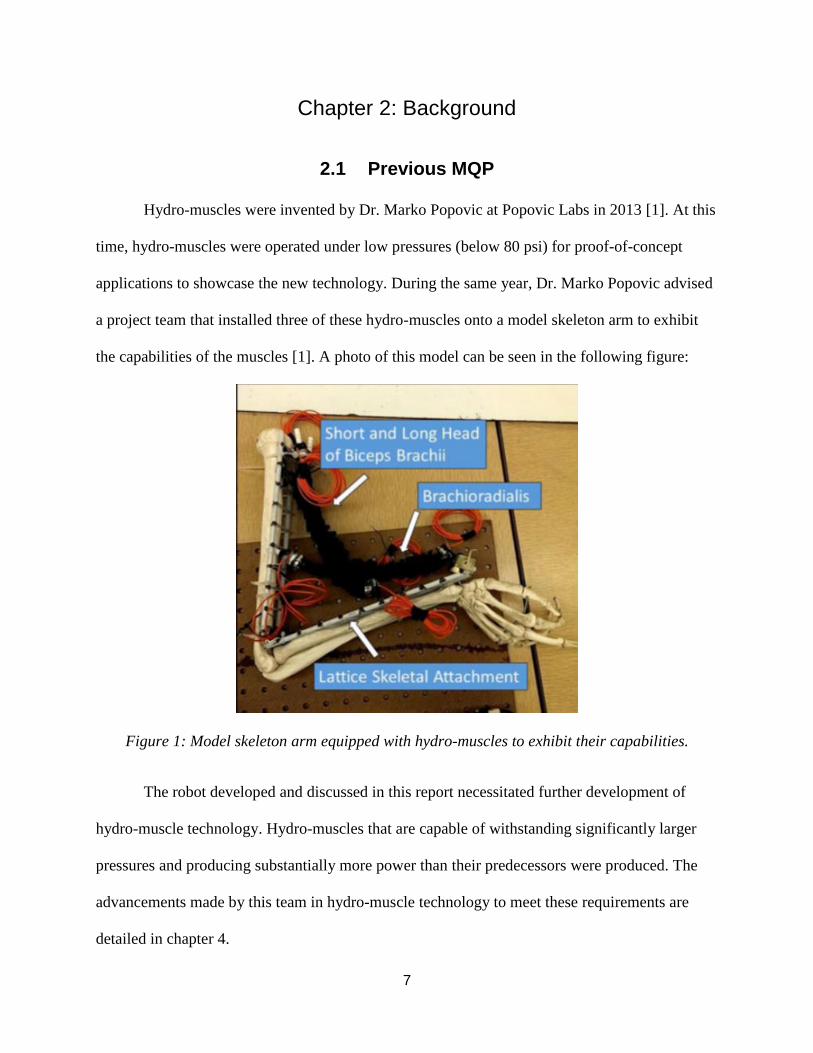
After performing preliminary research into hopping bipedal animals, the team decided to
model the design of the robot after the biology of kangaroos. The team then performed extensive
research into the dynamics of kangaroos in order to gain a better idea of how the robot should
9
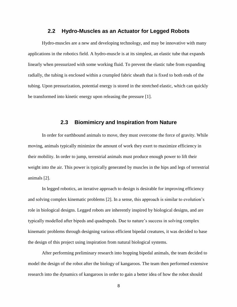
operate. A study reported by BBC News provided the majority of the background information
that gave inspiration for the final design of the robot [3]. The following images taken from the
study provide a visual key to understanding the train of thought that lead to the final design [3].
Figure 2: Stop motion filming of kangaroo. Blue circles mark the joints used in hopping.
Figure 3: Computer model generated from the stop motion film.
10
2.4 Existing Bipedal Robots
2.4.1 Festo BionicKangaroo
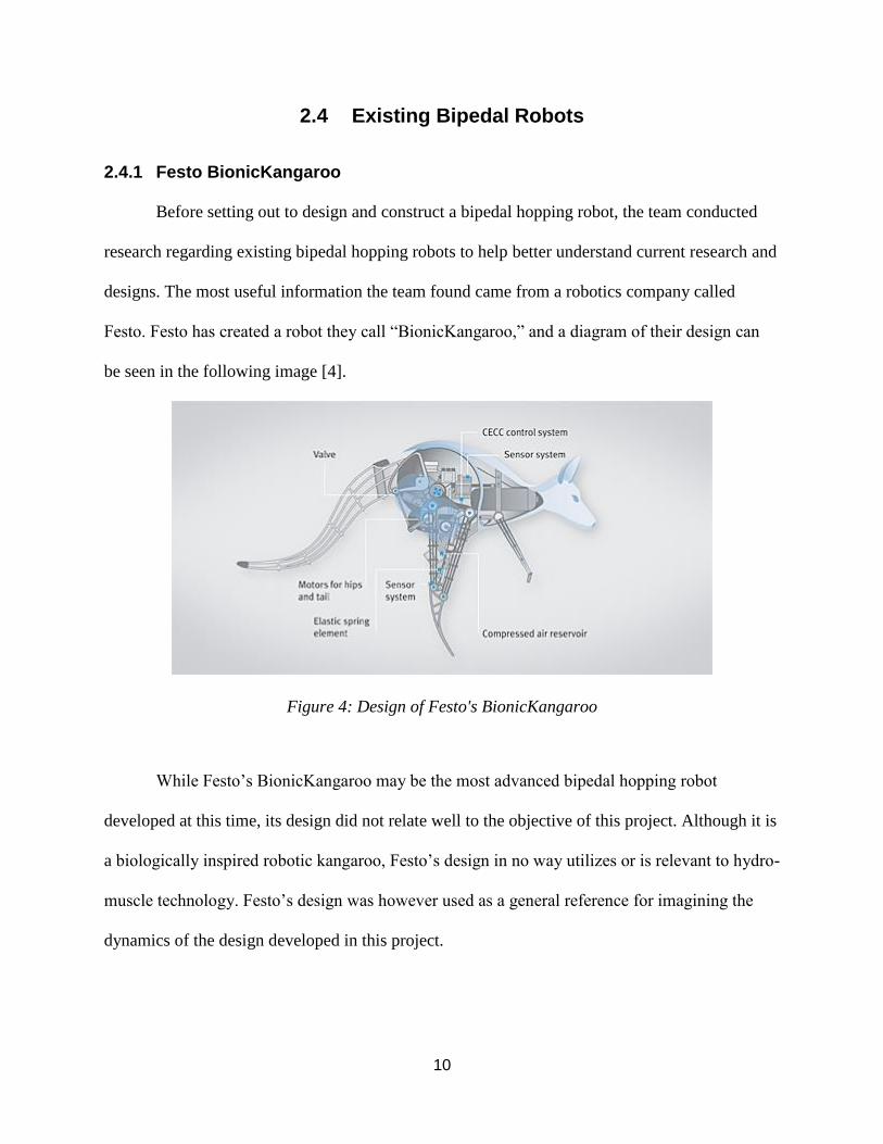
Before setting out to design and construct a bipedal hopping robot, the team conducted
research regarding existing bipedal hopping robots to help better understand current research and
designs. The most useful information the team found came from a robotics company called
Festo. Festo has created a robot they call “BionicKangaroo,” and a diagram of their design can
be seen in the following image [4].
Figure 4: Design of Festo's BionicKangaroo
While Festo’s BionicKangaroo may be the most advanced bipedal hopping robot
developed at this time, its design did not relate well to the objective of this project. Although it is
a biologically inspired robotic kangaroo, Festo’s design in no way utilizes or is relevant to hydro-
muscle technology. Festo’s design was however used as a general reference for imagining the
dynamics of the design developed in this project.
11
2.5 Advantages of Bipedal System for Hydro-Muscles
Bipedal systems carry many advantages in the field of robotics engineering. Bipedal
systems are statically stable, giving them the ability to maintain their position passively. They are
symmetrical about the sagittal plane, which greatly simplifies design and mathematical
modelling [2]. Furthermore, the positioning of bipedal systems before forming a jumping action
can be altered to change the trajectory of the jump. These advantages of bipedal systems are
extremely useful in accommodating control, design, and modelling of the project.
Performing a jumping action requires overcoming the force of gravity. Equipping a
bipedal system with hydro-muscles is an excellent way of demonstrating their high force output
capabilities. This is because performing a jumping action requires exerting a force larger than
that of gravity, which can be quite large depending on the weight of the object performing the
jump.
12
Chapter 3: Project Objectives
The purpose of this project was to demonstrate the high force output applications of
hydraulically actuated muscles through constructing a bipedal hopping robot. The team met with
the faculty advisor in the early stages of the project to outline the project objectives that would
drive the design. The main objectives that the team established for the design of the robot were:
1. To demonstrate and test the high-force applications of the hydro-muscles on legged
robots.
2. To develop a bipedal robot capable of jumping approximately one meter off the ground
using only the hydro-muscles for actuation.
3. To construct the robotic apparatus such that it serves as a suitable test bed for future
research involving high force output applications of the hydro-muscles.
4. To design the robotic apparatus and its components to be as modular as possible for easy
construction, deconstruction, and improvement.
5. To base the design of the robot around inspiration achieved from studying bipedal
hopping animals.
3.1 Determination of Design Specifications
Prior to beginning construction of the robot, the team met with the faculty advisor to
establish a series of specifications the design was expected to meet. The following sections
describe these specifications and explain the reasoning that led to the final design.
13
3.1.1 Size and Weight
The team desired to construct a robot that could be easily worked on and transported for
showcasing and different testing environments. The team decided that the robotic apparatus
should be large enough so it can be constructed with standard hardware, piping materials, and
tools, but small enough so it can be quickly transported for demonstrations. The robot should
also be sturdy enough to survive transportation without damage, and constructed such that
anyone, including children, can inspect and touch the apparatus without fear of injury.
Based on these desires, and the objective to have the robot capable of jumping
approximately one meter off the ground, the robot was decided to have a size comparable to a
red kangaroo with a weight no greater than 10 kilograms.
3.1.2 Cost
Legged robotic projects can quickly become very expensive and therefore inaccessible to
those without funding. Due to the low cost of producing the hydro-muscles, the team decided to
embrace the idea of being as cost effective as possible to help the technology become more
accessible.
The team calculated rough estimates for the cost of materials to construct the robot and
found that it should cost no more than $500 to build.
3.1.3 Actuation
Hydro-muscles are especially useful for their ability to augment power and for their
potential in fine position control when utilizing an incompressible fluid [1]. The faculty advisor,
and inventor of the hydro-muscles, wanted to further develop and test the technology through
14
this and other projects. Thus, the team decided to use the hydro-muscles as the only source of
actuation in the design of the robotic apparatus.
3.1.4 Locomotion
Performing a jump of approximately one meter in height requires simultaneous actuation
of both leg muscles. Each muscle requires two valves for actuation (or one two-way valve), one
for pressurizing fluid into the muscle(s) and one for opening the muscle(s) to atmospheric
pressure. Allowing for actuation of multiple degrees of freedom per leg would require more
valves on board the skeleton apparatus, and would not likely improve the jumping performance
of the robot. Furthermore, any additional weight added to the apparatus will result in decreasing
the height achieved by the robot in its jump.
Because the robot’s legs are required to be actuated simultaneously, the muscles of the
robot can be actuated in pairs. The pair of muscles on the bottom part of the skeleton can be
controlled with a single two-way valve, as well as the pair of muscles on the top part of the
skeleton. Allowing the top and bottom muscle groups to actuate independently allows for fine
tuning of the actuation timing for improving the robot’s jumping performance. As a result, the
team decided to equip the apparatus with a pair of digital two-way valves, one for each muscle
group.
3.1.5 Reconfigurability
Finding the ideal geometry for the robot’s legs before jumping would allow for an
optimized jumping performance. To help find this ideal geometry, the team conducted extensive
background research on the skeletal geometries of jumping bipedal organisms, including
15
kangaroos and humans. The team also researched previous projects involving hopping robots to
identify any observable trends in the geometries of their skeletons. Based on the research
obtained, no apparent trend exists, with robotic leg geometries varying enormously between
robots.
As a result, the team could not decide on any ideal skeleton geometry. In order to
maximize the odds of achieving a jump approximately one full meter in height from the ground,
the team decided to design a skeleton that is not bound to a permanent specific configuration.
This decision allows the user to quickly and easily change the size, placement, and orientation of
the robotic legs. Furthermore, the components attached to the legs, such as the hydro-muscles
and knee brackets, were decided to be constructed to allow easy interchangeability. These
decisions helped improve the modular and reconfigurable nature of the apparatus allowing any
user to quickly alter skeletal geometries in order to find the optimal parameters necessary for a
high jumping performance.
3.1.6 Future Platform for Hydro-Muscles
Considering the ambitious nature of this project being undertaken by only two students,
the team discussed with the faculty advisor the possibility of a future team picking up where this
year’s team left off. As a result, it was decided that the robot would serve as a test bed on which
future projects will build. Therefore, the specifics of the project design were decided to be easily
understandable and reproducible. The modular and reconfigurable aspects of the project play a
crucial role in this specification as future teams are expected to be able to alter the design and
change design components with ease.
16
3.2 Project Scope and Limitations
The core objective of this project was to design and implement a bipedal hopping robot
equipped with hydro-muscles to test the high force output applications of the muscles. Potential
future extensions to this project are numerous, but some of the more advanced functionality
usually found in robotic systems were determined to be beyond the scope of this project. Some
of the limitations on the functionality of the robot include, but are not limited to the following:
● Separate control of each leg
● Active repositioning of legs during aerial phase
● Passive weight distribution for landing
● Fine position control of the hydro-muscles
● Advanced modeling, simulations, and computer optimization
● More degrees of freedom (DoF)
● Directional control of robot trajectory
● Custom manufactured PCB components, valves, and hardware
● Advanced machining and fabrication techniques
● Navigation, mapping, obstacle avoidance
17
Chapter 4: Design and Construction
4.1 Reconfigurable Construction System
In chapter 3 it was stated that a reconfigurable skeleton is critically important for rapid
physical design testing and design alterations. The skeleton of the robot includes not only the
primary structural components used to build the main body of the robot, but also provides
mounting and attachment points, adjustment features, and the physical characteristics of the
robot. Before constructing the final skeleton with full modularity, a prototype was created to test
the practicality of using the hydro-muscles to make the skeleton jump. The prototype allowed for
easy construction and addition of muscles, but did not allow for quick changes in attachment
points.
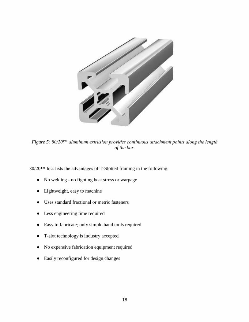
4.1.1 80/20™
After conducting extensive background research into possible construction systems, the
team decided to invest in 80/20™ Modular Framing. The 80/20™ Modular Framing consists of
extruded aluminum bars with a square profile featuring T-slots running along the length of every
side [5]. A profile of the 80/20™ extrusion can be seen in figure 5. The 80/20™ modular
framing is described by its creators as "The Industrial Erector Set"®, and it meets this
description with its versatile functionality. Users can quickly detach and reattach components, or
loosen an attachment to slide it along the bar and re-tighten them at any point along the 80/20™
bar [5].
18
Figure 5: 80/20™ aluminum extrusion provides continuous attachment points along the length
of the bar.
80/20™ Inc. lists the advantages of T-Slotted framing in the following:
● No welding - no fighting heat stress or warpage
● Lightweight, easy to machine
● Uses standard fractional or metric fasteners
● Less engineering time required
● Easy to fabricate; only simple hand tools required
● T-slot technology is industry accepted
● No expensive fabrication equipment required
● Easily reconfigured for design changes
19
The advantages listed above to using the 80/20™ aluminum extrusion closely match the
requirements of the robot's construction system. 80/20™ is available in a variety of sizes,
standards, profiles, and "series" of framing, each with their own accessories. For this project, the
20mm square "20 series" was chosen for constructing the skeleton of the robot as it is the
smallest and lightest profile available.
80/20™ is intended for load-bearing structures, so it is more than strong enough to
support what the skeleton of the robot requires [5]. However, these advantages result in the
80/20™ construction system being somewhat heavier than other similar aluminum construction
systems. Though it may be somewhat heavy in nature, the overwhelming adaptability of the
80/20™ 20-series was deemed to outweigh its weight concerns.
4.2 Skeleton Design
The design of the skeleton of the robot must allow for easy adjustment of the major
kinematic geometries while still providing structural stability, simplicity, modularity, and
maintaining a light weight.
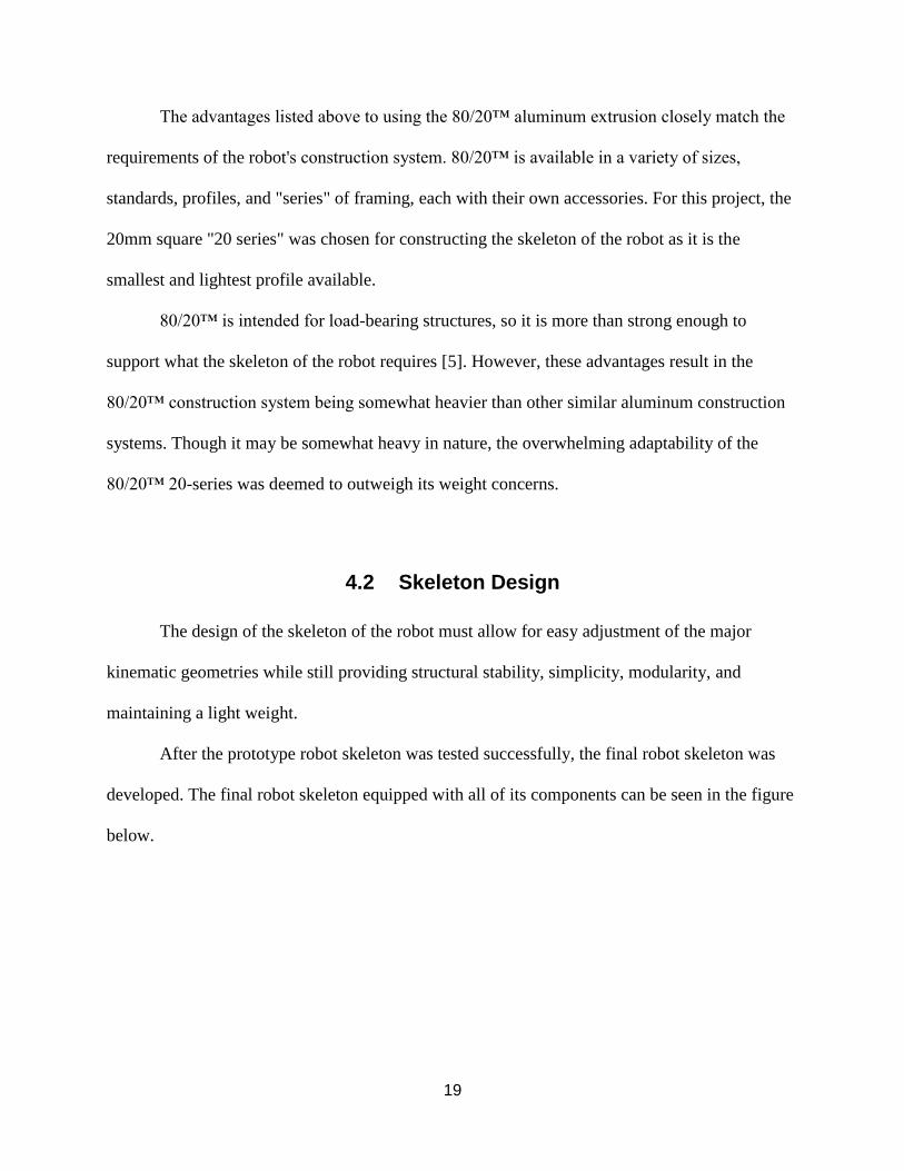
After the prototype robot skeleton was tested successfully, the final robot skeleton was
developed. The final robot skeleton equipped with all of its components can be seen in the figure
below.
20
Figure 6: The skeleton of the robot allows easy adjustments of all leg lengths, pivot points,
muscle attachment points, and center of mass adjustments.
4.3 Modelling and Simulation
A major advantage to constructing a rapidly reconfigurable test platform is that the robot
can be quickly reconfigured to match the configuration of a simulated bipedal model.
Optimization of the computer model and the resulting kinematic configuration can be quickly
mirrored on the physical robot to test the simulated model. With an accurate simulation and
21
suitable optimization algorithms, the kinematics of the robot can be optimized even faster than
the rapid reconfigurability of the skeleton would allow. Therefore, it was deemed that a
computational model and simulation for the robot would be extremely useful.
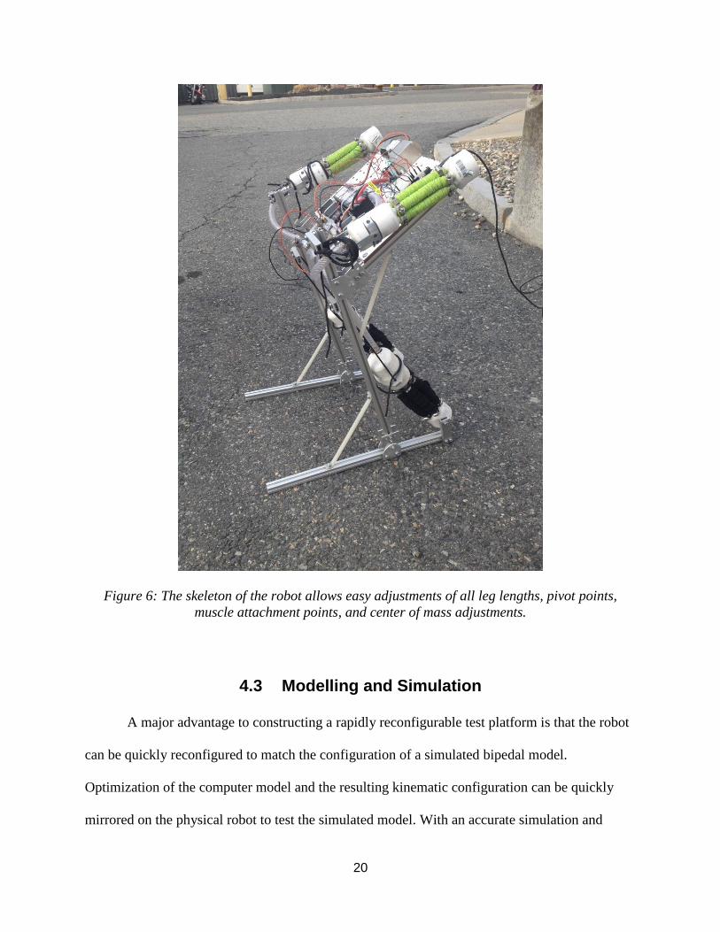
PTC Creo 3.0, a popular computer automated drafting (CAD) program, was used to
create the models of the robotic skeleton, as well as the simulations of the robot’s jumping
kinematics [6]. It was decided that advanced modeling, simulation, and optimization was outside
the scope of this project, and that a basic model and simulation would suffice as a proof of
concept that the robot can jump. The basic model running a jumping simulation can be seen in
the following figure:
Figure 7: Basic Creo model running a jumping simulation using the Creo software. The first
frame shows the robot in a pressurized state, ready for takeoff. The simulation models the hydro-
muscles as two sets of springs that actuate at the same time. The simulation was simplified by
pinning the toe of the robot to the ground – more advanced simulation was deemed unnecessary.
22
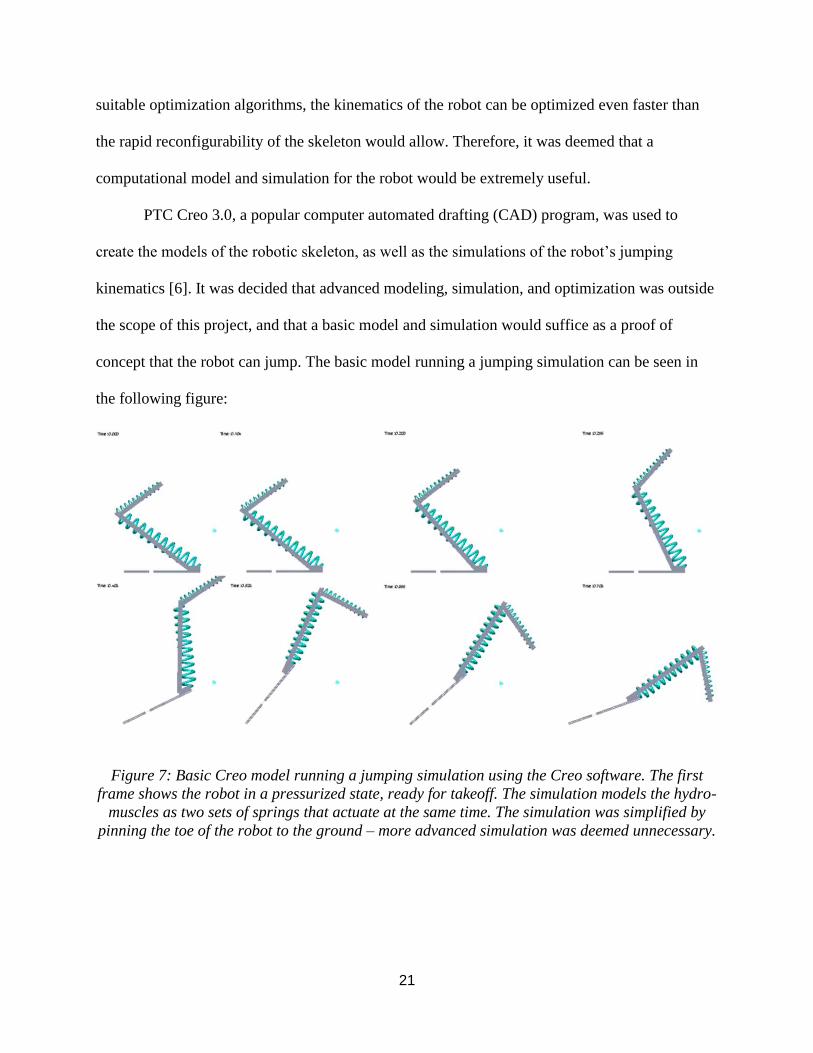
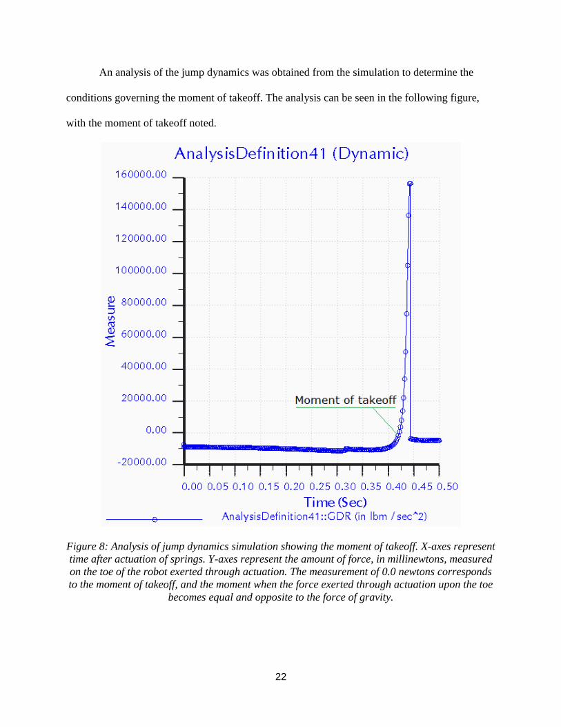
An analysis of the jump dynamics was obtained from the simulation to determine the
conditions governing the moment of takeoff. The analysis can be seen in the following figure,
with the moment of takeoff noted.
Figure 8: Analysis of jump dynamics simulation showing the moment of takeoff. X-axes represent
time after actuation of springs. Y-axes represent the amount of force, in millinewtons, measured
on the toe of the robot exerted through actuation. The measurement of 0.0 newtons corresponds
to the moment of takeoff, and the moment when the force exerted through actuation upon the toe
becomes equal and opposite to the force of gravity.
23
4.4 Hydro-Muscles as Actuators
The only actuator used to actuate the robot are the hydro-muscles. Connected to the legs
of the apparatus, the hydro-muscles provide the drive necessary to produce a jump.
The basic construction of a hydro-muscle consists of an elastomeric tube wrapped tightly
with a fabric sheath to prevent radial expansion [1]. As fluid is pumped into the muscle, the
fabric sheath constrains radial expansion and forces the hydro-muscle to expand linearly. Usually
plugged on both ends with barbed fittings, the barbs have the ability to serve also as mechanical
attachment points, allowing a tension force between these points to be generated as the muscle
contracts. At least one of the barbs has an opening that interacts with the fluidic system to allow
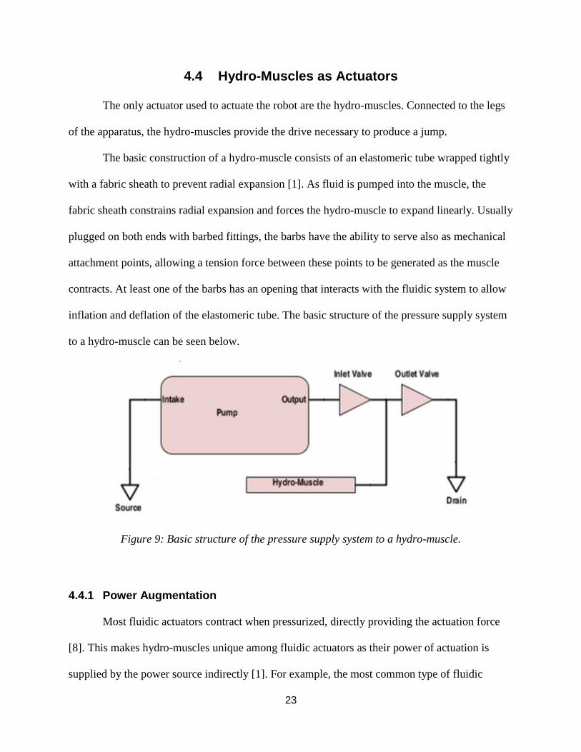
inflation and deflation of the elastomeric tube. The basic structure of the pressure supply system
to a hydro-muscle can be seen below.
Figure 9: Basic structure of the pressure supply system to a hydro-muscle.
4.4.1 Power Augmentation
Most fluidic actuators contract when pressurized, directly providing the actuation force
[8]. This makes hydro-muscles unique among fluidic actuators as their power of actuation is
supplied by the power source indirectly [1]. For example, the most common type of fluidic
24
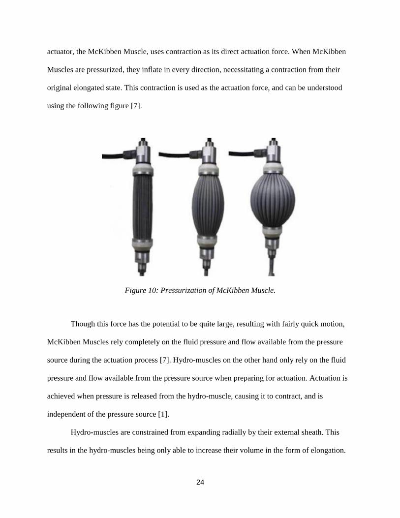
actuator, the McKibben Muscle, uses contraction as its direct actuation force. When McKibben
Muscles are pressurized, they inflate in every direction, necessitating a contraction from their
original elongated state. This contraction is used as the actuation force, and can be understood
using the following figure [7].
Figure 10: Pressurization of McKibben Muscle.
Though this force has the potential to be quite large, resulting with fairly quick motion,
McKibben Muscles rely completely on the fluid pressure and flow available from the pressure
source during the actuation process [7]. Hydro-muscles on the other hand only rely on the fluid
pressure and flow available from the pressure source when preparing for actuation. Actuation is
achieved when pressure is released from the hydro-muscle, causing it to contract, and is
independent of the pressure source [1].
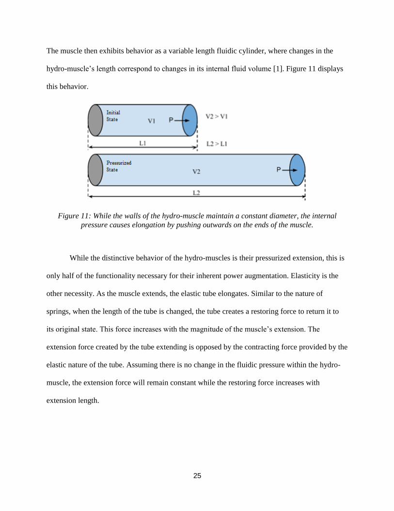
Hydro-muscles are constrained from expanding radially by their external sheath. This
results in the hydro-muscles being only able to increase their volume in the form of elongation.
25
The muscle then exhibits behavior as a variable length fluidic cylinder, where changes in the
hydro-muscle’s length correspond to changes in its internal fluid volume [1]. Figure 11 displays
this behavior.
Figure 11: While the walls of the hydro-muscle maintain a constant diameter, the internal
pressure causes elongation by pushing outwards on the ends of the muscle.
While the distinctive behavior of the hydro-muscles is their pressurized extension, this is
only half of the functionality necessary for their inherent power augmentation. Elasticity is the
other necessity. As the muscle extends, the elastic tube elongates. Similar to the nature of
springs, when the length of the tube is changed, the tube creates a restoring force to return it to
its original state. This force increases with the magnitude of the muscle’s extension. The
extension force created by the tube extending is opposed by the contracting force provided by the
elastic nature of the tube. Assuming there is no change in the fluidic pressure within the hydro-
muscle, the extension force will remain constant while the restoring force increases with
extension length.
26
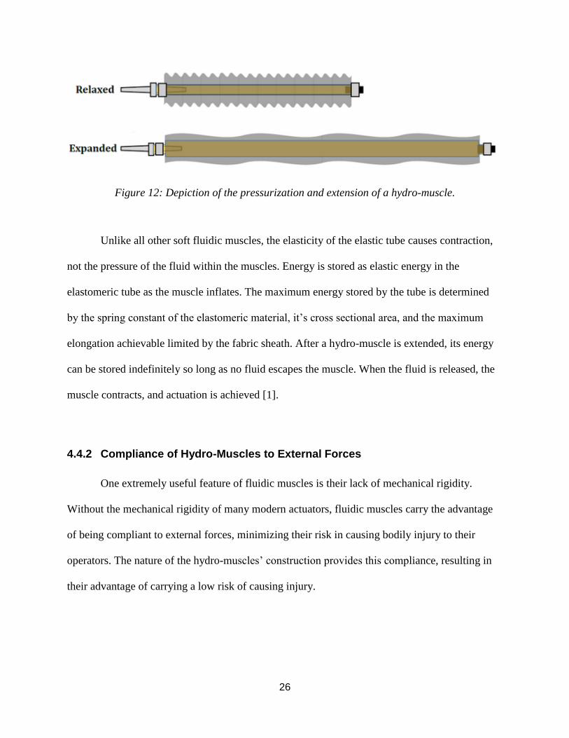
Figure 12: Depiction of the pressurization and extension of a hydro-muscle.
Unlike all other soft fluidic muscles, the elasticity of the elastic tube causes contraction,
not the pressure of the fluid within the muscles. Energy is stored as elastic energy in the
elastomeric tube as the muscle inflates. The maximum energy stored by the tube is determined
by the spring constant of the elastomeric material, it’s cross sectional area, and the maximum
elongation achievable limited by the fabric sheath. After a hydro-muscle is extended, its energy
can be stored indefinitely so long as no fluid escapes the muscle. When the fluid is released, the
muscle contracts, and actuation is achieved [1].
4.4.2 Compliance of Hydro-Muscles to External Forces
One extremely useful feature of fluidic muscles is their lack of mechanical rigidity.
Without the mechanical rigidity of many modern actuators, fluidic muscles carry the advantage
of being compliant to external forces, minimizing their risk in causing bodily injury to their
operators. The nature of the hydro-muscles’ construction provides this compliance, resulting in
their advantage of carrying a low risk of causing injury.
27
4.5 Fabrication of Hydro-Muscles
4.5.1 Elastomeric Tube
The elastomeric tubing serves as the main component of every hydro-muscle. The most
important factors that determine the behavior and functionality of the muscle are the choice of
material that comprises the tube, and the dimensions of the tube.
The primary function of the elastomeric tubing is to provide the contraction force
necessary to actuate the hydro-muscle. There are two factors that contribute to the contraction
force: the spring constant of the elastomeric tubing (k), and the displacement length (∆L) of the
muscle upon full extension. The spring constant of the elastomeric tubing is governed by two
separate factors, the total cross-sectional area of the material comprising the tube, and the
Young’s modulus of this material. Increasing either the total cross-sectional area of the tubing or
the Young’s modulus of the material will result in a larger spring constant, and thus a larger
contracting force.
Increasing the maximum extension of the muscle, the total cross-sectional area of the
tubing, or the Young’s modulus of the tubing material, will proportionally increase the hydro-
muscle’s force of actuation. Latex tubing was chosen as the elastomeric tubing, as it is widely
available in many sizes of both inner and outer wall diameters allowing for construction of
hydro-muscles with various spring constants.
4.5.2 Sheathing
The external sheathing of the hydro-muscle’s construction serves the following functions:
● Constraining the radial expansion of the elastomeric tubing.
28
● Allowing for longitudinal extension of the elastomeric tubing.
● Limiting the extension of the elastomeric tubing.
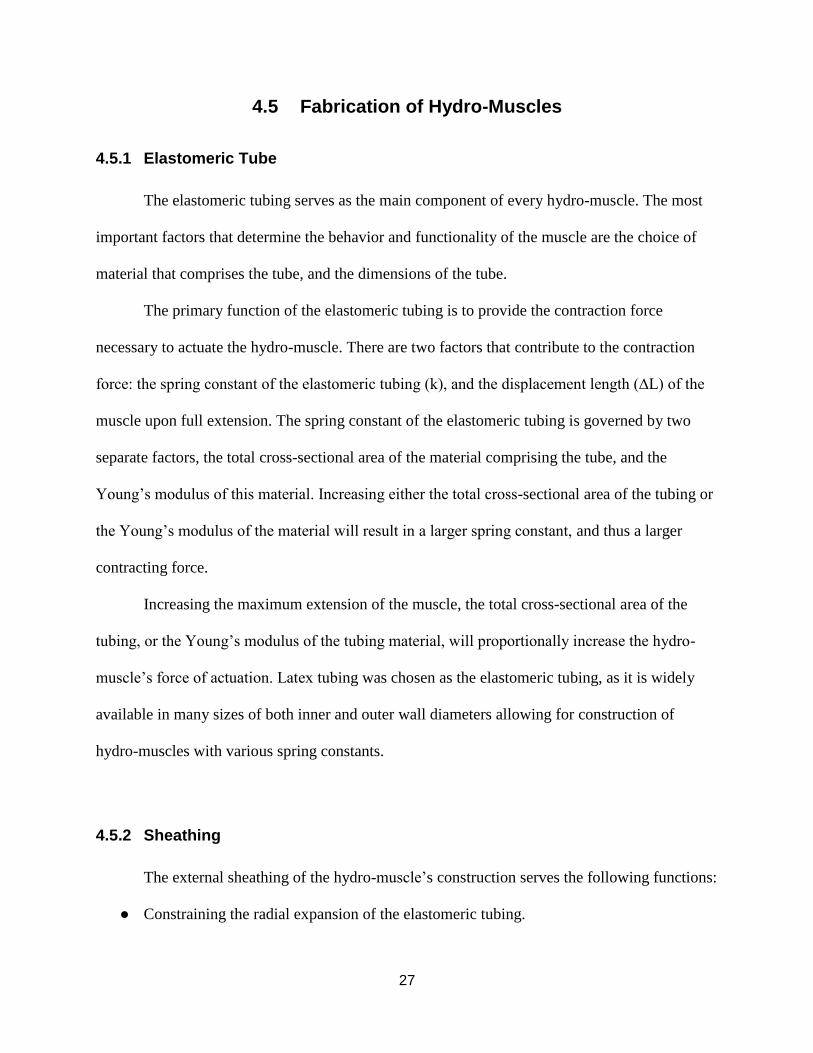
To adequately satisfy these functions, the sheathing must have a relatively high tensile
strength to constrain the tubing without ripping. Any failure in the sheathing will result in the
elastomeric tubing expanding radially and possibly breaking. Nylon tubular webbing was chosen
as the material to sheath the hydro-muscles due to its high tensile strength and because it is
available in a variety of sizes. The nylon tubular webbing used to construct the final iteration of
the hydro-muscles can be seen in the following figure.
Figure 13: Nylon tubular webbing serves as the sheathing that constrains the elastomeric tubing
in the hydro-muscle construction.
4.5.3 Barbed Fittings and Hose Clamps
Attached at both ends of the hydro-muscle are barbed nylon fittings secured with
standard hose clamps. The fittings and clamps are very cheap and readily available as standard
plumbing supplies. In the construction of a hydro-muscle, the nylon barbed fitting is inserted
barbs first into the elastomeric tube and then secured on with a suitably sized hose clamp. While
the fittings allow the flow of fluid to and from the hydro-muscles, they can also be used as
29
attachment points for mounting individual muscles. Barbed nylon fittings were chosen over brass
nylon fittings to minimize weight added to the robot.
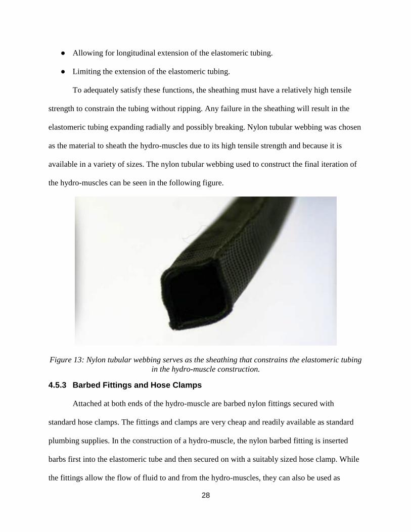
4.6 Parallel Operation
The power capable of being exerted by the hydro-muscles is limited by the size of their
constituent components. Latex tubing with the largest total cross-sectional area was used to
maximize the power attainable from the hydro-muscles. However, it was quickly realized that a
single hydro-muscle constructed to be as powerful as possible would come nowhere close to
being capable of lifting a 10 kilogram robot off of the ground. Thus, the team decided to utilize
many hydro-muscles in parallel through creating a system of muscle groups, or “muscle fibers”.
Utilizing many hydro-muscles in parallel allows for the restoring force of each extended muscle
to be added together to form the restoring force of the entire muscle fiber, similarly to how
springs operate in parallel. Both the prototype and final muscle fiber constructions can be seen in
the figures below.
Figure 14: Prototype muscle fiber. After testing the prototype muscle fibers, it was decided to
use larger tubing to increase the total force output.
30
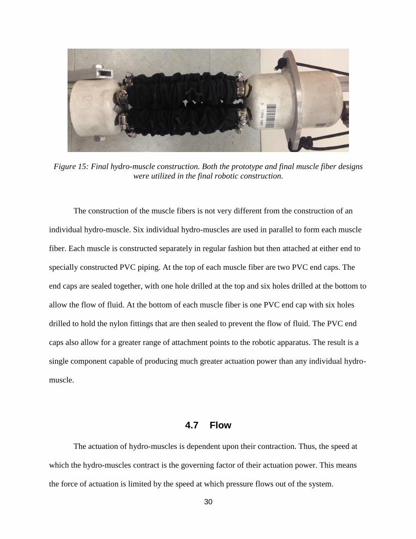
Figure 15: Final hydro-muscle construction. Both the prototype and final muscle fiber designs
were utilized in the final robotic construction.
The construction of the muscle fibers is not very different from the construction of an
individual hydro-muscle. Six individual hydro-muscles are used in parallel to form each muscle
fiber. Each muscle is constructed separately in regular fashion but then attached at either end to
specially constructed PVC piping. At the top of each muscle fiber are two PVC end caps. The
end caps are sealed together, with one hole drilled at the top and six holes drilled at the bottom to
allow the flow of fluid. At the bottom of each muscle fiber is one PVC end cap with six holes
drilled to hold the nylon fittings that are then sealed to prevent the flow of fluid. The PVC end
caps also allow for a greater range of attachment points to the robotic apparatus. The result is a
single component capable of producing much greater actuation power than any individual hydro-
muscle.
4.7 Flow
The actuation of hydro-muscles is dependent upon their contraction. Thus, the speed at
which the hydro-muscles contract is the governing factor of their actuation power. This means
the force of actuation is limited by the speed at which pressure flows out of the system.
31
Therefore, it is desirable to design a system that minimizes the time it takes for the system to
depressurize.
Water was used at first as a working fluid due to its nature as an incompressible fluid.
After initial testing, it was found that using water added far too much weight to the robot to make
any sort of jump feasible. Air was then tested as a replacement fluid, and was found to work
effectively in actuating the same hydro-muscles. Air added a negligible amount of weight to the
robot and was found to be released faster when depressurizing the system as compared to water.
The rate of flow out of the hydro-muscles can be optimized to increase the force of actuation.
4.8 Electrical System and Control Circuitry
4.8.1 Power Supply (Batteries)
Lithium Polymer (LiPo) batteries were chosen to serve as the on-board power supply.
LiPo batteries are a favorite among robotics hobbyists for their high energy density and their
capabilities in both high current output with a high capacity. For these reasons, as well as the
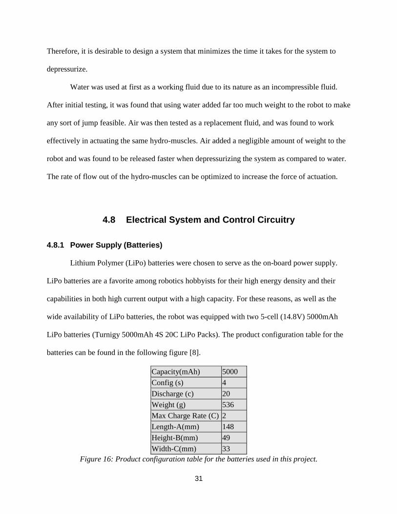
wide availability of LiPo batteries, the robot was equipped with two 5-cell (14.8V) 5000mAh
LiPo batteries (Turnigy 5000mAh 4S 20C LiPo Packs). The product configuration table for the
batteries can be found in the following figure [8].
Capacity(mAh) 5000
Config (s) 4
Discharge (c) 20
Weight (g) 536
Max Charge Rate (C) 2
Length-A(mm) 148
Height-B(mm) 49
Width-C(mm) 33
Figure 16: Product configuration table for the batteries used in this project.
32
4.8.2 Control Circuit
Each pair of hydro-muscles on the robot are controlled by a single two-way solenoid
valve. Each solenoid valve is controlled by a signal sent from the microcontroller to either open
or close the valves. A SunFounder 2 Channel 5V relay shield module and a breadboard make up
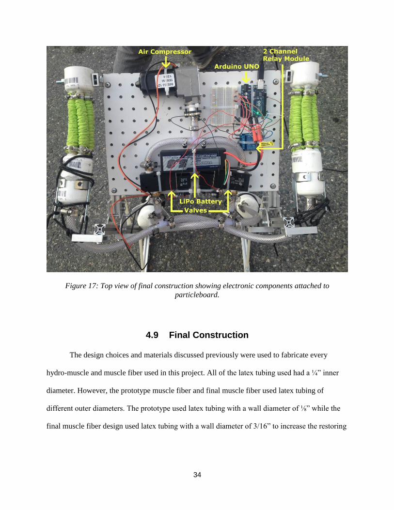
the control circuit, and can be seen in figure 17 [9].
4.8.3 Microcontroller
When choosing the microprocessor, three main considerations led to the selection:
processing power, available digital inputs, and available digital outputs. For a simple jumping
motion controlled manually or by a timer, processing speed on the order of one kilohertz is
acceptable. Thankfully, the requirements of this project fall within the realm of capabilities of
most modern common microprocessors.
Based on these requirements, an Arduino Uno was chosen as the microcontroller to
control the robot. The Arduino Uno operates at 16MHz, has 14 digital inputs and outputs, and is
one of the most well supported microcontrollers currently available [9]. The Arduino Uno
microcontroller can be seen equipped to the robot in figure 17.
4.8.4 Software System
Control of the robot is made possible by the software system. The software operates on
the Arduino Uno sending a signal to the fluidic solenoid valves, opening or closing the valves.
The software receives manual input and outputs a digital signal, causing actuation of the robot,
and a jump to occur.
The process by which the robot jumps occurs in the following sequence. First, a signal is
sent to the Arduino Uno, causing both valves to open one way, allowing flow of fluid into the
33
hydro-muscles. Once the hydro-muscles are fully extended, the fluidic pump is powered off to
stop the flow of fluid. From this point on, no energy is required to keep the robot in this state –
energy is only required to send the next signal to the valves to actuate the robot. When the next
signal is sent, the valves open in the other direction, allowing the fluid to be released from the
hydro-muscles.
Because this robot only needs to perform a high jumping action, no position control of
the muscles is necessary. Thus, the software is simplified to provide manual operation of the
valves. An example of the coding used to operate the robot can be found in the appendix.
A delay can be set in the software to allow the top and bottom valves to open one after
the other, allowing actuation of the top and bottom muscle groups separately. This delay can be
altered to control the trajectory of the jump more precisely. In this project, the top valves were
programmed to open slightly before the bottom valves, giving the robot a forward push before
the more powerful bottom muscles lift it upward.
34
Figure 17: Top view of final construction showing electronic components attached to
particleboard.
4.9 Final Construction
The design choices and materials discussed previously were used to fabricate every
hydro-muscle and muscle fiber used in this project. All of the latex tubing used had a ¼” inner
diameter. However, the prototype muscle fiber and final muscle fiber used latex tubing of
different outer diameters. The prototype used latex tubing with a wall diameter of ⅛” while the
final muscle fiber design used latex tubing with a wall diameter of 3/16” to increase the restoring
35
force generated by pressurizing the muscles. Both the prototype and final muscle fibers used 6
hydro-muscles in parallel.
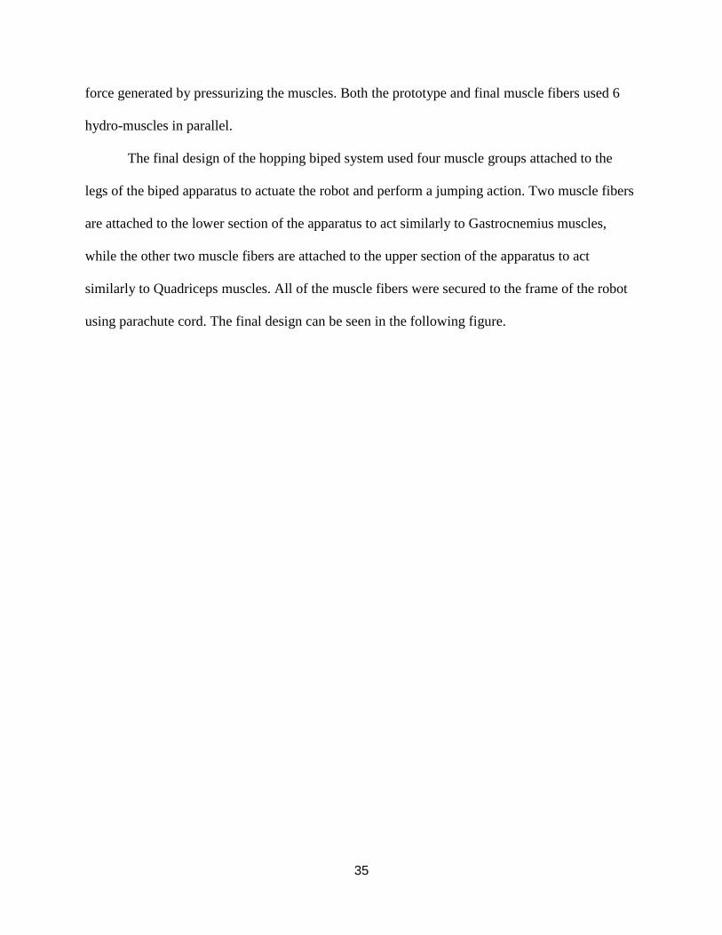
The final design of the hopping biped system used four muscle groups attached to the
legs of the biped apparatus to actuate the robot and perform a jumping action. Two muscle fibers
are attached to the lower section of the apparatus to act similarly to Gastrocnemius muscles,
while the other two muscle fibers are attached to the upper section of the apparatus to act
similarly to Quadriceps muscles. All of the muscle fibers were secured to the frame of the robot
using parachute cord. The final design can be seen in the following figure.
36
Figure 18: Iteration of the final construction with the prototype muscles used on top and the
more powerful muscles used beneath.
37
Chapter 5: Iterative Testing and Results
Methodology for Experimentation
5.1 First Test
5.1.1 Setup
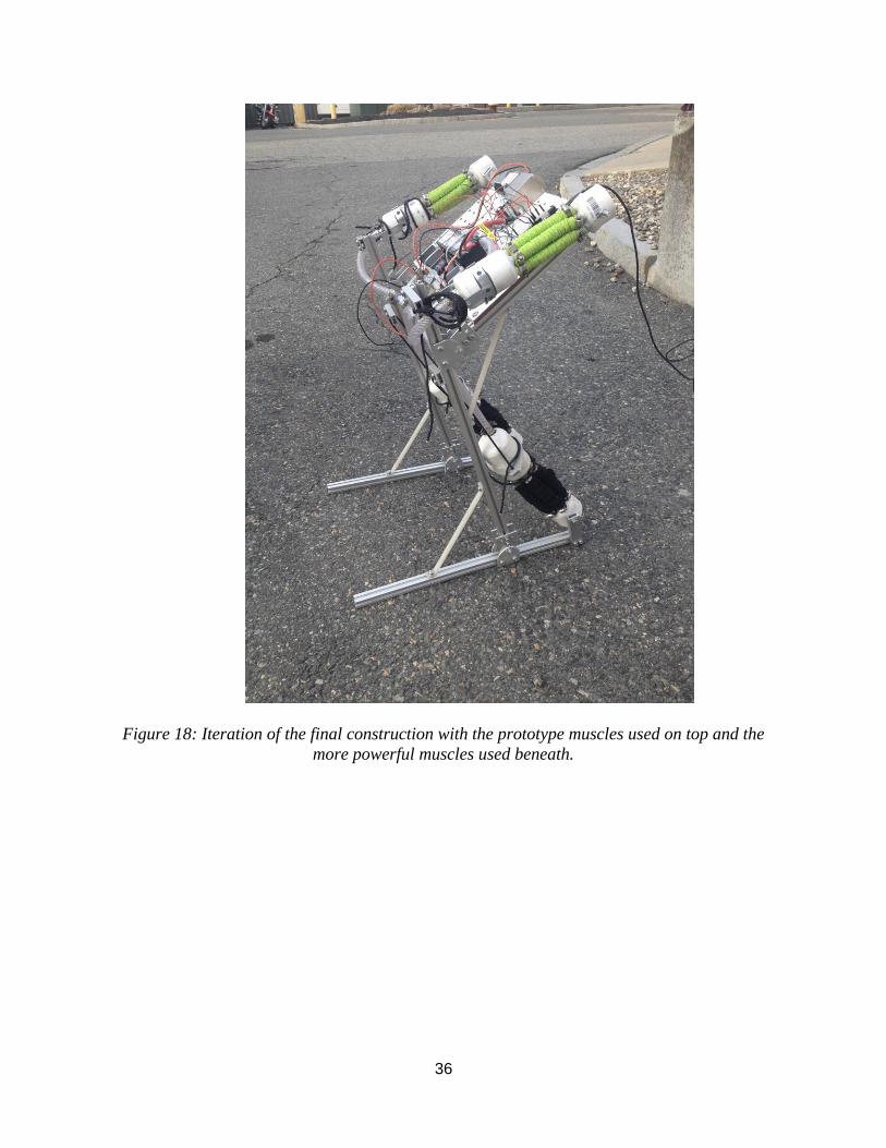
Once the team developed the muscle fiber prototype, experimentation using water as the
working fluid began immediately. The prototype muscle fiber extended to approximately twice
its original length with no issue. At this point, the team developed a prototype skeleton for the
robotic frame out of wood. A Creo computer model of the wooden prototype skeleton design can
be seen in the following figure [6].
Figure 19: Creo computer model of the wooden prototype skeleton design.
38
5.1.2 Response
While the prototype muscle fibers actuated the legs of the robot, they did not come close
enough to producing enough power to lift the robot from the ground. At this point, it was decided
that water added far too much weight to the robot to make any sort of jump feasible, especially if
the final skeleton design was to be robust and therefore heavier. Air was then tested as a
replacement fluid using a pneumatic pump, and was found to work effectively in actuating the
same hydro-muscles. The team then began design and construction of the final robotic skeleton
and created the more powerful muscle fibers.
39
5.2 Second Test
5.2.1 Setup
Once the team completed construction of the final robotic skeleton and the improved
muscle fibers, the team brought the completed robot outside to begin testing. The team was
hesitant to test the robot indoors due to the relatively large pressures being stored within the
muscle fibers. An exploding hydro-muscle could send components such as the hose clamps
flying as projectiles. From extensive prior testing of the muscle fibers, the team realized there is
very little risk of the hydro-muscles exploding under the testing conditions. However, the team
decided it was best to minimize every risk of possible injury. Thankfully, the robot operated
without any issue.
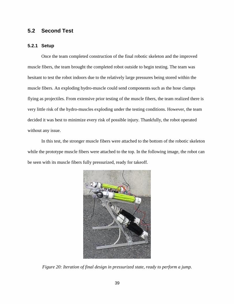
In this test, the stronger muscle fibers were attached to the bottom of the robotic skeleton
while the prototype muscle fibers were attached to the top. In the following image, the robot can
be seen with its muscle fibers fully pressurized, ready for takeoff.
Figure 20: Iteration of final design in pressurized state, ready to perform a jump.
40
5.2.2 Response
The muscle fibers actuated the legs of the robot with great success. While the force of
actuation was not large enough to lift the robot to the goal of approximately one meter off of the
ground, the team was satisfied with the performance achieved considering this was the first real
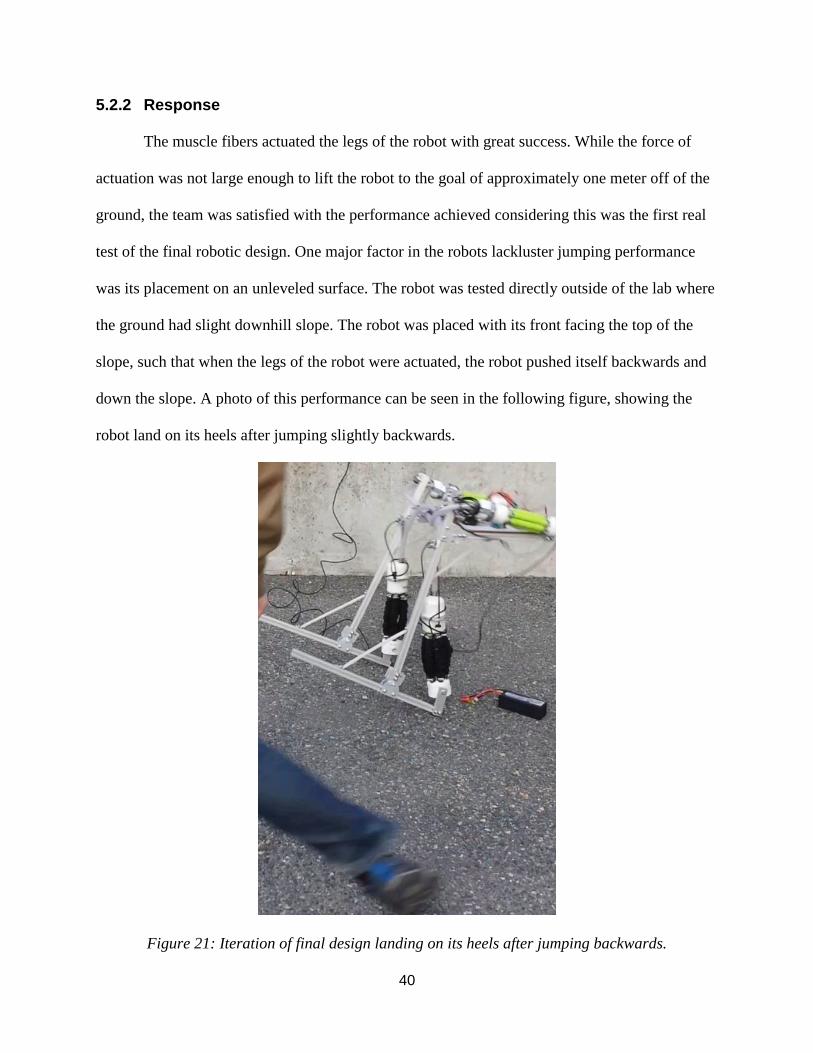
test of the final robotic design. One major factor in the robots lackluster jumping performance
was its placement on an unleveled surface. The robot was tested directly outside of the lab where
the ground had slight downhill slope. The robot was placed with its front facing the top of the
slope, such that when the legs of the robot were actuated, the robot pushed itself backwards and
down the slope. A photo of this performance can be seen in the following figure, showing the
robot land on its heels after jumping slightly backwards.
Figure 21: Iteration of final design landing on its heels after jumping backwards.
41
5.3 Third Test
5.3.1 Setup
Once the team successfully tested the final robotic design outdoors, the team moved
indoors to continue testing and improve the robots performance. The best results achieved by the
robot are described in the following.
The first improvement the team made to the design was to switch the top and bottom
muscle fibers. The team noticed that the bottom muscle fibers would have to extend much further
than the previous design iteration allowed during testing in order to perform a successful forward
jump. Although this meant placing the more powerful muscle fibers on the top of the robot, the
team found that this setup performed better than the previous iteration in giving the robot a slight
push forward before taking off into the air.
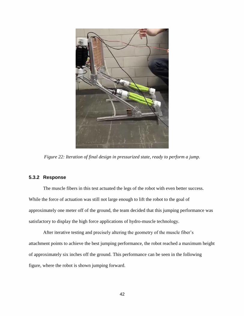
The following figure displays the robot with its muscle fibers fully pressurized, ready for
takeoff. In this image, a large rectangular block of aluminum can be seen under the heels of the
robot. This piece of aluminum was added to raise the back of the robot slightly, giving its legs a
better kinematic geometry for jumping.
42
Figure 22: Iteration of final design in pressurized state, ready to perform a jump.
5.3.2 Response
The muscle fibers in this test actuated the legs of the robot with even better success.
While the force of actuation was still not large enough to lift the robot to the goal of
approximately one meter off of the ground, the team decided that this jumping performance was
satisfactory to display the high force applications of hydro-muscle technology.
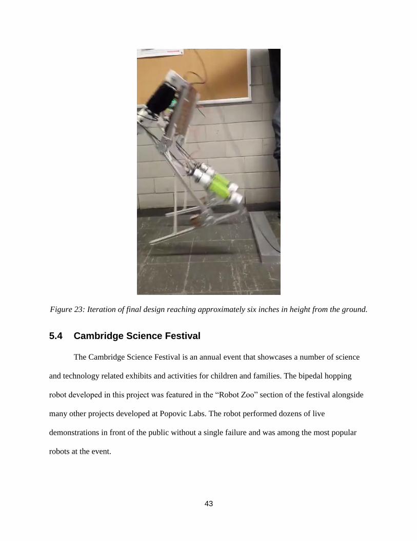
After iterative testing and precisely altering the geometry of the muscle fiber’s
attachment points to achieve the best jumping performance, the robot reached a maximum height
of approximately six inches off the ground. This performance can be seen in the following
figure, where the robot is shown jumping forward.
43
Figure 23: Iteration of final design reaching approximately six inches in height from the ground.
5.4 Cambridge Science Festival
The Cambridge Science Festival is an annual event that showcases a number of science
and technology related exhibits and activities for children and families. The bipedal hopping
robot developed in this project was featured in the “Robot Zoo” section of the festival alongside
many other projects developed at Popovic Labs. The robot performed dozens of live
demonstrations in front of the public without a single failure and was among the most popular
robots at the event.
44
Chapter 6: Conclusions
Hydraulically actuated muscles can be used for many high force applications. There are a
number of novel ways to increase the pulling force generated by muscle contractions to meet
many demands. The hopping bipedal robotic apparatus developed in this project serves as a
suitable test bed for demonstrating the hydro-muscles high force capabilities. Future research
will improve upon the robotic apparatus design and develop even more ways of increasing the
hydro-muscle’s pulling force.
6.1 Actuation and Locomotion
Following extensive testing of the many iterations of design, the robot successfully
performed a hop reaching approximately six inches off of the ground using only the hydro-
muscles as a source of actuation. Although the force of actuation from the muscle fibers was not
nearly large enough to lift the robot to the goal of approximately one meter off of the ground, the
team decided that this jumping performance was acceptable in displaying the high force
capabilities of hydro-muscle technology. Thus, the goal of demonstrating the high force output
applications of hydraulically actuated muscles through constructing a bipedal hopping robot was
deemed successful.
6.2 Reconfigurable Test Platform
The use of 80/20™ 20-series modular T-slotted aluminum extrusion exceeded
expectations and was crucial to meeting the goal of the project to design the robotic apparatus to
be as modular as possible for easy construction, deconstruction, and improvements. Besides
45
providing modularity, the 80/20™ extrusions helped make the robot structurally robust and
continuously adjustable such that the design met the goal of serving as a suitable test bed for
future research involving high force output applications of the hydro-muscles.
6.3 Future Work and Recommendations
Future projects regarding the high force output applications of the hydro-muscles or
working on the bipedal hopping robot test bed should focus on the following recommendations:
The kinematics of the apparatus and muscle placement can be fine-tuned to improve the
jumping performance of the robot. To further improve the actuation power of the hydro-muscles,
thicker latex tubing can be used to construct even stronger muscles. Furthermore, more hydro-
muscles can be integrated into each muscle fiber and the design of the muscle fibers can be
optimized to contain more hydro-muscles. The speed at which the muscle fibers contract can be
improved by using larger valves, tubing, and fittings to increase the flow of air, increasing the
actuation power of the hydro-muscles. Lastly, development of length control for the hydro-
muscles will allow for greater control of the robot during the pressurization phase.
46
Chapter 7: References
[1] N. Corso, D. Effraimidis, B. Jennings and G. McCarthy, 'Hydro Artificial Muscle Exo-
Musculature', Worcester Polytechnic Institute, Worcester, 2014.
[2] X. Zhou and S. Bi, 'A survey of bio-inspired compliant legged robot designs', Bioinspir.
Biomim., vol. 7, no. 4, p. 041001, 2012.
[3] J. Palmer, 'Kangaroo bounce mechanics illuminated by infrared study', BBC Science &
Environment, 2011.
[4] Festo.com, 'BionicKangaroo | Festo Corporate', 2015. [Online]. Available:
http://www.festo.com/cms/en_corp/13704.htm. [Accessed: 10- Jul- 2015].
[5] 8020.net, '80/20® Inc. - The Industrial Erector Set®', 2015. [Online]. Available:
http://www.8020.net/. [Accessed: 10- Aug- 2015].
[6] Creo.PTC.net, 'Creo.ptc.com: Creo PTC 3.0’, 2015. [Online]. Available:
http://www.ptc.com/product/creo/new. [Accessed: 10- Aug- 2015].
[7] G. Klute, J. Czerniecki and B. Hannaford, 'McKibben artificial muscles: Pneumatic
actuators with biomechanical intelligence', IEEE/ASME, 1999.
[8] HobbyKing Store, 'Turnigy 5000mAh 4S 20C Lipo Pack', 2015. [Online]. Available:
http://www.hobbyking.com/hobbyking/store/__9177__Turnigy_5000mAh_4S_20C_Lipo_Pack.
html. [Accessed: 10- Jun- 2015].
[9] Amazon.com, 'Amazon.com: SunFounder 2 Channel 5V Relay Shield Module for
Arduino UNO 2560 1280 ARM PIC AVR STM32 Raspberry Pi: Computers & Accessories',
2015. [Online]. Available:
http://www.amazon.com/gp/product/B00E0NTPP4?psc=1&redirect=true&ref_=oh_aui_detailpa
ge_o03_s00. [Accessed: 10- Jul- 2015].
47
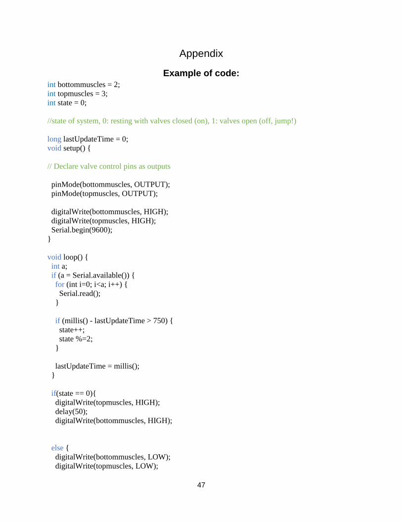
Appendix
Example of code: int bottommuscles = 2;
int topmuscles = 3;
int state = 0;
//state of system, 0: resting with valves closed (on), 1: valves open (off, jump!)
long lastUpdateTime = 0;
void setup() {
// Declare valve control pins as outputs
pinMode(bottommuscles, OUTPUT);
pinMode(topmuscles, OUTPUT);
digitalWrite(bottommuscles, HIGH);
digitalWrite(topmuscles, HIGH);
Serial.begin(9600);
}
void loop() {
int a;
if (a = Serial.available()) {
for (int i=0; i<a; i++) {
Serial.read();
}
if (millis() - lastUpdateTime > 750) {
state++;
state %=2;
}
lastUpdateTime = millis();
}
if(state == 0){
digitalWrite(topmuscles, HIGH);
delay(50);
digitalWrite(bottommuscles, HIGH);
else {
digitalWrite(bottommuscles, LOW);
digitalWrite(topmuscles, LOW);
48
}
}