legacy processor and device support for fully virtualized
TRANSCRIPT

Universitat Karlsruhe (TH)Institut fur
Betriebs- und Dialogsysteme
Lehrstuhl Systemarchitektur
Legacy Processor and Device Support for FullyVirtualized Systems
Michael Schilli
Studienarbeit
Verantwortlicher Betreuer: Prof. Dr. Frank Bellosa
Betreuender Mitarbeiter: Dipl.-Inf. Jan Stoß
4. Oktober 2007

Hiermit erklare ich, die vorliegende Arbeit selbstandig verfasst und keine anderen als die angegebe-
nen Literaturhilfsmittel verwendet zu haben.
I hereby declare that this thesis is a work of my own, and that only cited sources have been used.
Karlsruhe, den 4. Oktober 2007
Michael Schilli

Abstract
With recent processor extensions the IA-32 architecture became effectively virtualiz-
able. The L4 microkernel already provides the necessary extensions to support Intel’s
VT-x technology and the Afterburner framework was recently extended to introduce
a user level monitor on top of L4. This work proposes two extensions to the existing
framework to support legacy processor and devices in a fully virtualized system. The
resulting implementation will provide a fully 16-bit compatible execution environment
and will allow guest operating systems access to an existing hard disk drive.
v

vi
Contents
1 Introduction 1
2 Background and Related Work 2
2.1 Virtualization . . . . . . . . . . . . . . . . . . . . . . . . . . . . . . 2
2.1.1 Full Virtualization . . . . . . . . . . . . . . . . . . . . . . . 2
2.1.2 Para-Virtualization . . . . . . . . . . . . . . . . . . . . . . . 2
2.1.3 Hardware-assisted Virtualization . . . . . . . . . . . . . . . . 3
2.2 IBM PC Hardware Platform . . . . . . . . . . . . . . . . . . . . . . 3
2.2.1 Memory Model . . . . . . . . . . . . . . . . . . . . . . . . . 4
2.2.2 BIOS Interrupt Services . . . . . . . . . . . . . . . . . . . . 5
2.3 Intel VT-x . . . . . . . . . . . . . . . . . . . . . . . . . . . . . . . . 5
2.4 Xen . . . . . . . . . . . . . . . . . . . . . . . . . . . . . . . . . . . 6
3 Design and Implementation 7
3.1 Architecture . . . . . . . . . . . . . . . . . . . . . . . . . . . . . . . 7
3.1.1 L4/VT Extensions . . . . . . . . . . . . . . . . . . . . . . . 8
3.2 Legacy Processor Support . . . . . . . . . . . . . . . . . . . . . . . 9
3.2.1 BIOS Services . . . . . . . . . . . . . . . . . . . . . . . . . 10
3.2.2 Starting a virtual machine . . . . . . . . . . . . . . . . . . . 11
3.3 IDE Emulation . . . . . . . . . . . . . . . . . . . . . . . . . . . . . 12
3.3.1 Generic PCI IDE controller . . . . . . . . . . . . . . . . . . 13
3.3.2 DMA Acceleration . . . . . . . . . . . . . . . . . . . . . . . 14
4 Evaluation 16
4.1 Booting . . . . . . . . . . . . . . . . . . . . . . . . . . . . . . . . . 16
4.2 Hard Disk Drive . . . . . . . . . . . . . . . . . . . . . . . . . . . . . 17
A Supported BIOS Services 18
vii
Chapter 1
Introduction
With the development of recent processor architectures, virtualization found its way
even into desktop systems and notebooks. Once confined to specialized, proprietary,
high-end server and mainframe systems, today it is used in applications like server
consolidation, migration, device driver reuse and secure computing. This progress
was due to steady performance improvements which led to applicable performance
overheads.
In virtualization, a hypervisor, also called virtual machine monitor (VMM), is a
software program that manages multiple operating systems on a single computer. More
precisely, it manages the system’s processor, memory and other resources, such as de-
vices, and allocates what each operating system requires. There are generally two dif-
ferent types of hypervisors. The first type runs directly on the given hardware, whereas
the second type requires a host operating system.
The L4 microkernel already provides the necessary extensions to support hardware
virtualization such as Intel VT-x [4]. It acts as a hypervisor that runs directly on the
given hardware, without the need of a host operating system. The recently extended
Afterburner framework [3] provides a set of servers and devices models to support a
user level VMM on top of L4.
The goal of this thesis is to extend the existing user level VMM to support legacy
devices in a hardware-based virtualization environment. The resulting VMM will be
able to offer a completely compatible 16-bit execution environment and will success-
fully boot FreeDOS, a free MS-DOS clone. Furthermore the VMM will be able to
provide arbitrary guest operating systems with an interface to access an existing hard
disk drive by emulating an IDE hard disk and a controller. This enables us to share a
given hard disk among several different guest operating systems.
1

Chapter 2
Background and Related Work
In this chapter I will first give a brief introduction to the different virtualization tech-
niques currently used, ranging from full virtualization to contemporary hardware-based
virtualization. In the next section I will describe some details of a standard PC system,
which are necessary for virtualization to provide guest operating systems with their
preconditioned environment. In section 2.3 I will provide a short introduction to In-
tel VT-x, a hardware virtualization extension for the IA-32 architecture. In the last
section I will present Xen, which has become a popular open source virtualization soft-
ware over the last years and with its recent versions is also capable to utilize hardware
virtualization extensions such as Intel VT-x.
2.1 Virtualization
2.1.1 Full Virtualization
The full virtualization approach provides a total abstraction of the underlying physical
hardware. No modification to the guest OS or application is required and consequently
the guest OS or application is not aware of running in a virtualized environment. This
can be advantageous, because it completely decouples the software from the hardware.
However, this approach can also result in performance loss. Support for full vir-
tualization was never part of the x86 architectural design, therefore all privileged in-
structions must be handled by the VMM for correct virtualization. Software also has
to provide a complete image of a system, including virtual memory, virtual BIOS, and
virtual devices. It has to maintain data structures for these virtual entities, that must be
updated with every guest access.
Well known software, that uses full virtualization, is for example VMware Work-
station, ESX Server, and Player.
2.1.2 Para-Virtualization
In contrast to full virtualization, the para-virtualization approach requires modification
to the guest OS. It avoids some drawbacks of full virtualization by presenting an ab-
straction of the hardware which is similar but not identical to the underlying physical
hardware. Virtualization-sensitive instructions in the guest OS are replaced by calls
to a VM monitor. As a result of the virtualization-aware guest OS, this approach can
2
CHAPTER 2. BACKGROUND AND RELATED WORK 3
reach near-native performance. One of the disadvantages of this approach is the need
of access to the source code to perform the necessary modifications, which also limits
the range of possible guest operating systems.
2.1.3 Hardware-assisted Virtualization
Recent development in processor architecture has originated in processor extensions
to support virtualization. Intel’s Vanderpool (Intel-VT) and AMD’s Pacifica (AMD-V)
technology help to simplify the task of processor virtualization by transferring some of
the complexity that arise from virtualization, from software to hardware. Each virtual
machine has its own hardware and allows a guest OS to be run in isolation.
In contrast to para-virtualization, the guest OS can execute directly on the pro-
cessor and therefore no modification to the guest are necessary, which allows to run
unmodified guest operating system similar to full virtualization. But experiments [2]
have shown, that hardware-assisted virtualization still underachieves in performance,
caused by the lack of optimizations.
2.2 IBM PC Hardware Platform
The original IBM Personal Computer (IBM PC) was first introduced in 1981. Based
on the Intel x86 architecture, that first appeared in the Intel 8086 processor released in
1979, IBM used an Intel 8088 processor; a successor of the 8086 but with only an 8-bit
external data bus (instead of 16-bit). The only proprietary component of the PC was
the basic input/output system (BIOS). After successful introduction on the computer
market, various manufactures started building their own PC compatible computers by
duplicating nearly all significant features including the BIOS, that was legally reverse
engineered. All computers that were software compatible with the original IBM PC
were generally referred as IBM PC compatible. This section gives an overview of the
IBM PC compatible hardware platform as seen from the operating system.
Since the introduction of the first IBM PC, the basic system startup procedure has
not changed. Most of the necessary initialization is done by the BIOS [8], that resides in
a ROM on the mainboard (today in a EEPROM/FLASH-ROM). Once power is applied
to the PC, the BIOS startup code is executed. Having set up hardware devices and
interrupt handlers (see 2.2.2), the BIOS initializes the system, performs a power-on
self-test (POST), determines a bootable device and initiates the bootstrap sequence,
which in turn boots an operating system (OS).
The Intel 8088 processor, as used in the original IBM PC, was able to address up
to 1MB of physical memory, limited by its 8-bit external data bus. Section 2.2.1 shows
the typical memory configuration of this 1 MB after successful BIOS initialization.
Later on, in 1986, Intel introduced the 80386, which was the first x86 processor to
have a 32-bit architecture. To ensure backward compatibility, it was still able to execute
native 16-bit code with a special processor mode, called real-address mode. The ex-
ecution environment of the processor in real-address mode was designated to provide
the execution environment of the original Intel 8086 with a nominal 1 MB physical
address space. Successive implementations of this architecture, which remained com-
pletely backwards compatible, were often termed i386 or IA-32 architecture.
Even today, with recent 32-bit or even 64-bit processors, systems still start in real-
address mode to maintain full backward compatibility. Although the term IBM PC
compatible is not commonly used for current computers anymore, the basic execution
CHAPTER 2. BACKGROUND AND RELATED WORK 4
environment is still comparable with the original IBM PC and operating systems are
expected to start in real-address mode. However, to accommodate the fact that today
the majority of systems expected to run are 32-bit operating systems, there has been
established a 32-bit code interface for BIOS services, called BIOS32 Service Direc-
tory [5]. This interface is now part of the Peripheral Component Interconnect (PCI)
standard.
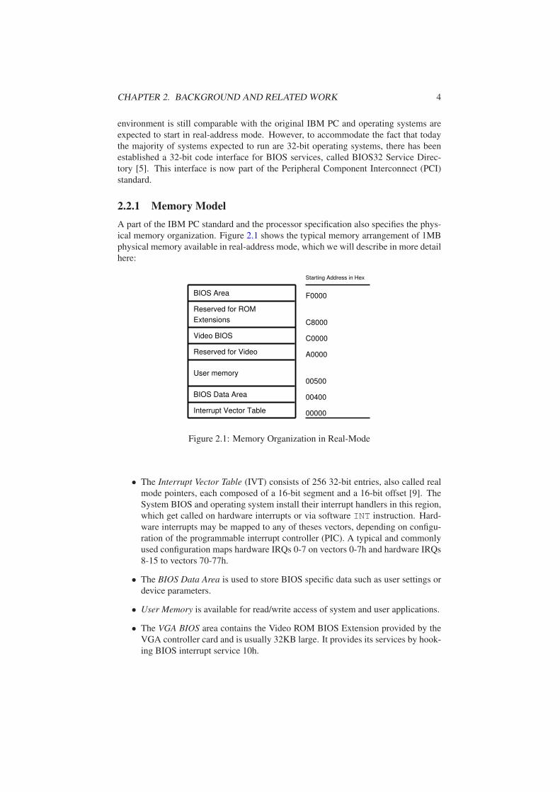
2.2.1 Memory Model
A part of the IBM PC standard and the processor specification also specifies the phys-
ical memory organization. Figure 2.1 shows the typical memory arrangement of 1MB
physical memory available in real-address mode, which we will describe in more detail
here:
Interrupt Vector Table
BIOS Area
Video BIOS
00000
C0000
C8000
F0000
00400BIOS Data Area
00500User memory
A0000Reserved for Video
Reserved for ROM
Extensions
Starting Address in Hex
Figure 2.1: Memory Organization in Real-Mode
• The Interrupt Vector Table (IVT) consists of 256 32-bit entries, also called real
mode pointers, each composed of a 16-bit segment and a 16-bit offset [9]. The
System BIOS and operating system install their interrupt handlers in this region,
which get called on hardware interrupts or via software INT instruction. Hard-
ware interrupts may be mapped to any of theses vectors, depending on configu-
ration of the programmable interrupt controller (PIC). A typical and commonly
used configuration maps hardware IRQs 0-7 on vectors 0-7h and hardware IRQs
8-15 to vectors 70-77h.
• The BIOS Data Area is used to store BIOS specific data such as user settings or
device parameters.
• User Memory is available for read/write access of system and user applications.
• The VGA BIOS area contains the Video ROM BIOS Extension provided by the
VGA controller card and is usually 32KB large. It provides its services by hook-
ing BIOS interrupt service 10h.

CHAPTER 2. BACKGROUND AND RELATED WORK 5
• The ROM BIOS Extensions area, as well as the VGA BIOS area, is inspected by
the BIOS during POST to detect ROM Extensions. An existing ROM Extension
is located with the help of a special signature at the beginning.
• The BIOS Area contains the systems BIOS itself and is usually 64KB large.
2.2.2 BIOS Interrupt Services
One of the initial goals of BIOS Interrupt Services was to provide an operational in-
terface to the system and to relieve the programmer of direct interaction with hardware
devices. The BIOS interface together with the application programming interface (API)
of the operating system formed what would now be called a hardware abstraction layer
(HAL). This abstraction layer made it possible to run the same operating system or ap-
plication on any compatible computer, regardless of variations in hardware equipment.
Therefore, most operating systems rely on services provided by the BIOS, especially
older legacy 16-bit operating systems make heavy use of theses services to interact with
hardware devices such as disk drives, keyboard and display. Modern operating systems
mostly rely on their own specific hardware device drivers and use BIOS services only
during system startup [16].
Over the years the number of services provided by the BIOS has become pretty
large. With each new developed hardware device, there has been introduced a new
BIOS services to support it. As of today, there are about 9000 different known ser-
vices [7].
2.3 Intel VT-x
Virtualization was never part of the IA-32 architectural design. Several virtualization
sensitive instructions prevents it from being effectively virtualizable. Although it is
possible to create virtual machines on IA-32 architecture with techniques like full or
para-virtualization, this results in either high engineering costs or performance losings.
With recent processors Intel implemented an extension called VT-x, which reduces
engineering efforts and eliminates the need of special virtualization techniques.
The Intel VT-x processor extension introduces two new processor modes; VMX
root and VMX non-root mode. Both modes provide all 4 privilege levels (0-3) as on
native IA-32 architecture, allowing the virtual machine monitor (VMM) and the guest
to be run with its intended privilege level. VT-x also introduces two new transitions;
VM-exit and VM-entry. VM-Exit switches from non-root to root mode, whereas VM-
Entry switches reverse. The VMM runs in root mode and controls the execution envi-
ronment of the guest, that runs in non-root mode, with the help of the virtual machine
control structure (VMCS). The VMCS controls the behavior of VM-Exits, VM-Entries,
and the processor in non-root mode and consists of two different areas, the guest-state
and host-state area, which contain fields that corresponds to the different registers and
controls of a physical processor. A VM-Entry loads parts from the guest-state area
and resumes execution. It can also be used to inject an event such as exceptions or
interrupts into the guest. A VM-Exit stores the actual processor state in the guest-state
area and loads the host-state area. The VMCS also contains fields that control which
events or instructions in non-root mode cause a VM-Exit. The cause of an exit can be
obtained by reading the basic exit reason register.

CHAPTER 2. BACKGROUND AND RELATED WORK 6
2.4 Xen
Xen [18] is a popular free software virtual machine monitor (VMM) for IA-32, x86-64,
IA-64 and Power-PC architecture. Using the para-virtualization approach, it requires
modification to both, the guest and host operating system, which limits the range of
available host and guest systems to mainly Unix-like systems. In doing so Xen achieves
a high performance. Although Microsoft Research, along with the University of Cam-
bridge Operating System group, developed a port of Windows XP for Xen, it was not
published due to licensing restrictions.
With the release of Xen 3.0 in december 2005, the development of recent hardware
extensions was taken into account, and support for hardware-assisted virtualization
was added, allowing Xen to run unmodified guests such as Microsoft Windows XP.
To provide the necessary execution environment to start unmodified guests, Xen uses
parts of a full system emulation from Qemu [15]. This subset of Qemu emulates all
important I/O parts of a PC, including a PCI bridge, a VGA card, PS/2 mouse and
keyboard, hard disk and floppy disk, network card, sound card, usb controller as well
as a complete PC BIOS. With this virtualization environment Xen is currently able to
run certain versions of Windows (including XP) and Linux as unmodified guests using
hardware virtualization.
Chapter 3
Design and Implementation
In this chapter we present the design and some important aspects of the implemen-
tation to support legacy devices in a hardware-based virtualization environment. We
focus on two important devices here; legacy processor and hard disk drive emulation,
because both devices are essential parts of a minimal and fully usable virtualization
environment.
Legacy processor support is important to provide arbitrary guest operating systems
with a 16-bit execution environment that is completely compatible to native hardware,
that means we should be able to run unmodified native 16-bit operating systems. This
introduces two main issues that have to be solved. The first one is to allow the guest
to run the processor in 16-bit mode (also called real-address mode) and the second one
is provide the necessary platform environment as already described in the related work
chapter.
Hard disks are a minimal system requirements for most operating systems as well,
because they expect to store application and/or system specific data on a nonvolatile
media. Hard disk emulation addresses an approach to share one or more existing phys-
ical hard disks among different guest operating systems.
This chapter is organized as follows: The next section gives an overview of the
currently used virtualization architecture, called Afterburner. The following section
covers details, necessary to fully support native 16-bit operating systems, including
BIOS functions. The last section describes the approach used to provide each guest
with an interface to access an existing hard disk drive.
3.1 Architecture
The Afterburner framework [1] provides a set of tools and servers to support virtual-
ization on L4. Originally, its main target was to support pre-virtualization, a technique
similar to para-virtualization. Pre-virtualization maintains hypervisor and guest OS
neutrality by introducing an automated two stage process. In the first stage the com-
piler automatically locates privileged instructions and pads them with spaces. The
produced binary executes both on raw hardware and on a virtual machine monitor. In
the second stage the VMM rewrites the sensitive instructions at runtime.
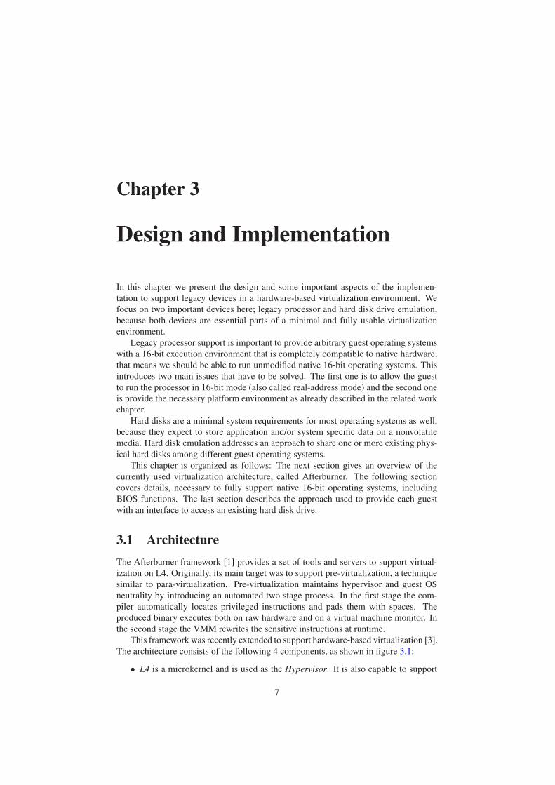
This framework was recently extended to support hardware-based virtualization [3].
The architecture consists of the following 4 components, as shown in figure 3.1:
• L4 is a microkernel and is used as the Hypervisor. It is also capable to support
7
CHAPTER 3. DESIGN AND IMPLEMENTATION 8
VMM1 VMM2 VMM3
Guest
1
Resource Monitor
L4
Guest
3
Guest
2
Figure 3.1: Virtualization Architecture
hardware assisted virtualization [4], what we will describe in more detail in the
next section.
• Resource Monitor is the root server of all virtual machine monitors. Its task
is to manage all physical resources available and hand them out to the virtual
machines if necessary; it ensures however, that only one virtual machine gets a
physical resource at a particular time (except for shared devices). During system
startup, the resource monitor creates one virtual machine monitor per virtual
machine and allocates the requested size of memory, as specified at command
line.
• The Virtual Machine Monitor (VMM) manages the virtual machine environment.
Most importantly, the VMM handles privileged instructions executed by the
guest operating system. Depending on the VMM’s type, instructions involving
device accesses are either emulated in the VMM itself, or forwarded to the real
hardware. At the moment, the VMM is capable of emulating a programmable
interrupt controller (PIC), a peripheral component interconnect (PCI) bus, and a
serial port controller.
• Guest hosts the guest operating system.
3.1.1 L4/VT Extensions
The L4 microkernel is a second generation microkernel developed by the System Ar-
chitecture Group at the University of Karlsruhe. It provides abstractions for address
spaces, threads and communication primitives (Inter Process Communication - IPC).
Recent processor architectures introduced hardware extensions to support virtualiza-
tion. To support the Intel VT-x hardware virtualization in L4, some small changes on
the thread and address space abstractions were required. These modifications can be
classified into the following 4 categories:
VCPU Thread L4 already provides the abstraction of threads. To represent the pro-
cessor of a virtual machine, the thread control blocks (TCBs) were extended to include
the Virtual Machine Control Structure (VMCS), that contains the virtual processor
state.
CHAPTER 3. DESIGN AND IMPLEMENTATION 9
VM-Exit Handler On virtualization sensitive instructions the processor generates a
VM-Exit and stores the current processor context into the guest state area of the VMCS.
Additionally, the VM-Exit handler stores the remaining processor context (general pur-
pose registers) onto the kernel stack. After this, the cause of the exit is obtained by read-
ing the appropriate VMCS field. After handling the fault the VCPU context is reloaded
and execution of the VM is resumed with a VM-Entry, that switches to non-root mode.
Virtualization Fault Protocol On most VM-Exits, L4 generates a virtualization fault
message and sends it to the corresponding VMM via standard IPC mechanism, similar
to page faults. The message contains the exit reason and, depending on the reason,
additional information such as guest register content. The VMM can then handle the
fault and send back a virtualization reply message, again via IPC. The reply messages
allows the VMM to modify the VCPU state, request additional state, or simply resume
execution. It can also be used to inject events such as exceptions or interrupts into the
guest.
Shadow Pagetable The shadow pagetable provides the necessary management to
support virtual memory. Instead of having access to real physical memory, the guest
OS runs in its own L4 address space, backed by virtual memory, and has to consider
this as physical memory. This introduces two translations: from guest-virtual to guest-
physical and from guest-physical to host-physical. The shadow pagetable caches theses
two translations in a single translation (guest-virtual to host-physical). When the guest
is running, the processor then uses the shadow pagetable for address translation.
3.2 Legacy Processor Support
When a processor is powered up or reset, it is placed in real-address (16-bit) mode.
This mode is almost identical to the execution environment of the Intel 8086 processor.
Virtually any program developed to run an on Intel 8086 processor will also run on IA-
32 processors in this mode. To provide guest operating systems in an hardware-based
virtualization environment with this mode, several constraints have to be considered;
first of all security. The guest application should be run in a protected environment,
which prevents it from interfering with any other applications or components in the
system, especially with the hypervisor (L4).
On the IA-32 processor architecture, there are the following three possibilities to
support 16-bit mode compatible with the original 8086 processor [10]:
• Real-address mode provides the programming environment of the original Intel
8086 on newer CPUs; it does not provide any protection to the hypervisor.
• Virtual-8086 mode provides virtually the same environment as real-address mode,
i.e. it emulates an Intel 8086 processor. But actually it is a special type of a task
that runs in protected mode. The major difference between the two modes is that
in virtual-8086 mode the emulator uses some protected-mode services such as
interrupt and exception-handling and paging facilities.
• Full Emulation uses an instruction set emulator to emulate a 8086 processor
in the VMM, which is always possible, independent from the processor archi-
tecture. However, the speed penalty inherent in interpretation of the executed
instructions is generally too high.
CHAPTER 3. DESIGN AND IMPLEMENTATION 10
Using real-address mode is not possible, because is not supported in VMX operation
on current VT-x processors. Full emulation would introduce a too high performance
penalty. Using the remaining virtual-8086 mode also assures the mandatory protec-
tion to run native 16-bit programs. The special exception-handling capabilities of this
mode, also allows the VMM to handle privileged instructions. Whenever a 16-bit pro-
gram tries to execute a sensitive instruction, the processor raises a general-protection-
fault (GP). The hypervisor (L4) then sends a fault message to the corresponding VMM
thread, which handles the faulting instruction. That means it either emulates the in-
struction or executes it on bare hardware and returns the result, depending on the VMM
type.
However, support for running the processor in 16-bit mode is not yet sufficient
to create an execution environment compatible with the original IBM platform; we are
still missing the important BIOS services. The next section is dedicated to this problem
and section 3.2.2 finally shows how we start a completely compatible virtualization
environment.
3.2.1 BIOS Services
To further enhance 16-bit compatibility, we also have to provide the native execution
environment of a PC, as described earlier. This includes to provide all BIOS Services
commonly used by older and newer operating systems.
We decided to use an already existing open source System BIOS and VGA BIOS
implementation, originally developed for the Bochs IA-32 Emulator [6]. This imple-
mentation is widely-used in open source virtualization and system emulator projects [15,
18] and has proven to be stable and complete in terms of supported guest operating sys-
tems.
When operating in real-address mode, the VMM must provide appropriate interrupt-
handling facilities, which also implicates access to the BIOS services. The VMM
differentiates between the two types of interrupts; Hardware interrupts and Software
interrupts. Hardware Interrupts are generated either by virtual or real devices and the
VMM receives a request to inject an interrupt with the corresponding vector number,
dependent on the PIC configuration. Software Interrupts are issued from the guest op-
erating system via the INT instruction and the VMM receives a virtualization fault
message from L4. On both interrupt types, the VMM request additional VCPU state
before continuing. This includes the SP, EFLAGS, IP, CS, and SS registers. The CS,
IP and EFLAGS register are pushed onto the guests stack to allow the IRET instruc-
tion at the end of the interrupt handler procedure to resume execution of the interrupted
program. The VMM then looks up the corresponding interrupt vector in the guest’s
interrupt vector table. With the virtualization fault reply message, it sets the new stack
and instruction pointer, that will execute the appropriate BIOS or OS interrupt handler
on VM resume.
One of the problems that arose during testing was caused by the fact that the BIOS
was originally developed for the BOCHS IA-32 emulator, that emulates a complete x86
environment, including all common hardware devices. In conjunction with a VMM
that forwards device access to the real hardware, several devices did not work prop-
erly, mainly caused by timing dependencies. Timing problems occurred, when the
BIOS was waiting for a device to complete a requested operation. In a fully emulated
environment most of the emulated devices complete an operation prior to resuming ex-
ecution of the guest; however on real device access this is not the case. The required
waiting time is spend in a so called delay loop, which is a simple loop repeated for a
CHAPTER 3. DESIGN AND IMPLEMENTATION 11
specified number of times. On faster processors however, these loops are generally exe-
cuted too fast, resulting in completion at at time when the device has not yet completed
its operation. It was therefore necessary to modify some delay loops, i.e. increase the
loop count, which solved the problems in the majority of cases.
3.2.2 Starting a virtual machine
At system startup we have to take care, that the execution environment is set up cor-
rectly to run native 16-bit guests. The whole system is started with the help of the
GRUB bootloader. The desired virtualization environment, that supports legacy pro-
cessor and devices, is configured via command line parameters. An exemplary GRUB
boot entry would look like:
kernel=(nd)/tftpboot/schilli/kickstart kmem=64M
module=(nd)/tftpboot/schilli/pistachio-vt
module=(nd)/tftpboot/schilli/sigma0
module=(nd)/tftpboot/schilli/l4ka-resourcemon
module=(nd)/tftpboot/schilli/afterburn-wedge-l4ka-guest-vdev \
vmstart vmsize=512M wedgeinstall=16M wedgesize=32M hd0=33,1 hd1=33,2
module=(nd)/tftpboot/schilli/systembios
module=(nd)/tftpboot/schilli/vgabios
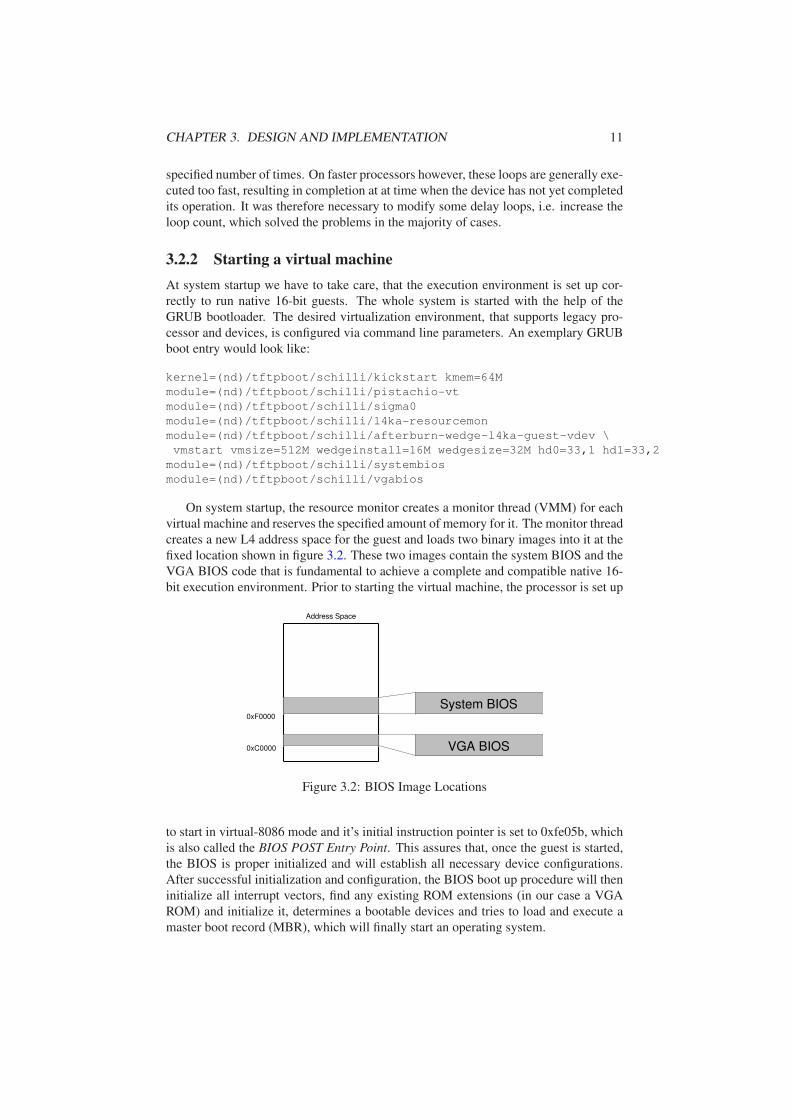
On system startup, the resource monitor creates a monitor thread (VMM) for each
virtual machine and reserves the specified amount of memory for it. The monitor thread
creates a new L4 address space for the guest and loads two binary images into it at the
fixed location shown in figure 3.2. These two images contain the system BIOS and the
VGA BIOS code that is fundamental to achieve a complete and compatible native 16-
bit execution environment. Prior to starting the virtual machine, the processor is set up
Address Space
VGA BIOS
System BIOS0xF0000
0xC0000
Figure 3.2: BIOS Image Locations
to start in virtual-8086 mode and it’s initial instruction pointer is set to 0xfe05b, which
is also called the BIOS POST Entry Point. This assures that, once the guest is started,
the BIOS is proper initialized and will establish all necessary device configurations.
After successful initialization and configuration, the BIOS boot up procedure will then
initialize all interrupt vectors, find any existing ROM extensions (in our case a VGA
ROM) and initialize it, determines a bootable devices and tries to load and execute a
master boot record (MBR), which will finally start an operating system.

CHAPTER 3. DESIGN AND IMPLEMENTATION 12
3.3 IDE Emulation
To share an existing hard disk drive among several different guest operating systems,
we have to provide each guest with an interface to access it. The Advanced Technology
Attachment (ATA) standard, also known as Integrated Drive Electronics (IDE), is a
quasi standard interface for connecting storage devices such as hard disk and CD-ROM
to a personal computer for almost 20 years. Recent versions of this standard allow to
connect up to four devices and specify both programmed input/output (PIO) and direct
memory access (DMA) transfers, which permits transfer rates of up to 133 MB/s.
In this section we describe a software emulated ATA (IDE) controller and hard disk,
realized with the help of a device driver operating system (DD/OS) [13]. The DD/OS
introduces a client-server model, that enables any external processes (clients) access
to its device drivers. This is necessary because of the stateful design of an ATA disk
controller. Independent from the data corruptions that can occur, when multiple guests
use the same filesystem at a time, an IDE controller is not capable of handling multiple
access from different operating systems. The DD/OS enables us to share existing hard
disks at the granularity of partitions. That means it is possible to make e.g. the first
partition available to one guest and the second partition of the same hard disk available
to another guest.
VMM1 VMM2
Guest DD/OS
Shared Memory Shared Memory
Block Server
Native Hard Disk
Virtual Hard Disk
Request
Figure 3.3: DD/OS - Client Architecture
DD/OS
The device driver operating system (DD/OS) provides the necessary interface to access
a hard disk from external applications. The DD/OS itself is a special guest OS with
legacy device drivers, that have passthrough access to the native hardware. Running
the device drivers with its original operating system enables extensive reuse of existing
device drivers and reduces engineering effort. Hosting the DD/OS in its own virtual
machine also isolates the devices drivers from other components, which reduces effects
of malfunctioning devices and/or drivers and generally improves the system depend-
ability.
To provide clients access to its devices, the DD/OS exports a virtual interface to the
Block Server, that allows access to the linux block layer. Devices are addressed over
their corresponding major/minor number [14].
All requests are managed through a shared memory concept, as shown in figure 3.3.
On client registration the server makes several pages of shared memory available to the
client. This memory is arranged as a ring descriptor or producer-consumer ring as used
CHAPTER 3. DESIGN AND IMPLEMENTATION 13
in Xen [18].
When the client issues a request, the VMM injects a virtual interrupt into the
DD/OS to cause invocation of the appropriate block server function. When the server
signals the client in response, the VMM injects a virtual interrupt as well.
3.3.1 Generic PCI IDE controller
IDE controllers have a well known programming interface at fixed addresses and using
fixed IRQs. Most OSes, particularly older and native 16-Bit ones - including the BIOS,
have code that deals directly with this interface. It is therefore essential to support this
interface in order to provide guest operating systems with access to hard disk drives.
This also assures that we sustain compatibility with older systems and cover a large
base of supported platforms.
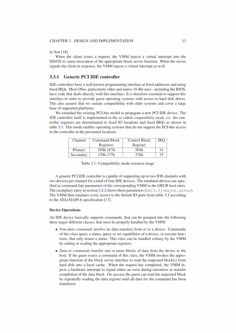
We extended the existing PCI-bus model to propagate a new PCI IDE device. The
IDE controller itself is implemented in the so called compatibility mode, i.e. the con-
troller registers are determinated to fixed IO locations and fixed IRQs as shown in
table 3.1. This mode enables operating systems that do not support the PCI-bus access
to the controller at the presumed locations.
Channel Command Block
Registers
Control Block
Register
IRQ
Primary 1F0h-1F7h 3F6h 14
Secondary 170h-177h 376h 15
Table 3.1: Compatibility mode resource usage
A generic PCI IDE controller is capable of supporting up to two IDE channels with
two devices per channel for a total of four IDE devices. The emulated devices are spec-
ified as command line parameters of the corresponding VMM in the GRUB boot entry.
The exemplary entry in section 3.2.2 shows these parameters (hd[0,3]=major,minor).
The VMM then emulates every access to the default IO ports from table 3.1 according
to the ATA/ATAPI-6 specification [17].
Device Operations
An IDE device basically supports commands, that can be grouped into the following
three major different classes, that must be properly handled by the VMM:
• Non-data commands involve no data transfers from or to a device. Commands
of this class query a status, query or set capabilities of a device, or execute func-
tions, that only return a status. This class can be handled solitary by the VMM
by setting or reading the appropriate registers.
• Data-in commands transfer one or more blocks of data from the device to the
host. If the guest issues a command of this class, the VMM invokes the appro-
priate function of the block server interface to read the requested block(s) from
hard disk into a local cache. When the request has completed, the VMM in-
jects a hardware interrupt to signal either an error during execution or transfer
completion of the data block. On success the guest can read the requested block
by repeatedly reading the data register until all data for the command has been
transfered.
CHAPTER 3. DESIGN AND IMPLEMENTATION 14
• Data-out commands transfer one or more blocks of data from the host to a de-
vice. If the guest issues a command of this class, it first transfers the block(s) by
repeatedly writing to the data register. The VMM saves this data in a local cache
and as soon as all data for the command has been transfered, the VMM issues a
block server to transfer the data out of the cache onto the hard disk. Again, the
VMM injects a hardware interrupt to signal either success or error.
On bare hardware PIO mode operation requires a great deal of CPU overhead to
configure a data transaction and transfer the data. In hardware-assisted virtualization
environments however, this method further decreases performance. Each IO port ac-
cess involves a privileged instruction, which will generate lots of traps to the hypervi-
sor. Because of this general inefficiency of PIO mode operations, it was advantageous
to implement some kind of DMA transfers, which we will present in the following
section.
3.3.2 DMA Acceleration
Today, many hardware systems use direct memory access (DMA) including disk drive
controllers, graphics cards, network cards, and sound cards. DMA channels allow to
transfer data to and from devices with much less CPU overhead than without a DMA
channel. Because the DD/OS linux itself uses DMA to transfer the requested data, it
offers the possibility to provide an emulated DMA disk controller for the guest as well.
This allows transferring data to and from the guest directly, without an indirection over
the VMM’s local cache. In contrast to other virtualization software, the DMA transfers
will not be software emulated but executed on a real DMA controller, resulting in a real
reduction of CPU load.
A very important consideration when choosing a device to emulate is how broadly
supported it is. We choose to implement the IDE controller part of the Intel 82371AB
(PIIX4) [12], a common bus master DMA controller that is supported by a large number
of platforms. The bus master programming interface is an extension of the standard
IDE programming interface. This means that devices can always be addressed using the
standard interface, with the bus master functionality only used when appropriate. This
also means that the generic IDE controller is a prequisite for using DMA functionality.
The three basic classes of device operation apply for DMA accelerated transfers as
well, and are handled from the VMM almost identical.
As with the generic PCI IDE controller, the existing PCI-bus model was extended to
propagate the new device and to determine the I/O ports for device access. Any access
to these ports claimed by the DMA controller are trapped and emulated according to
the specification.
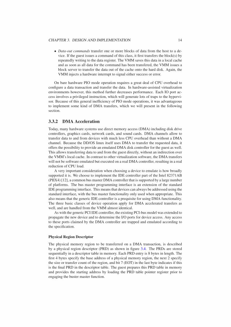
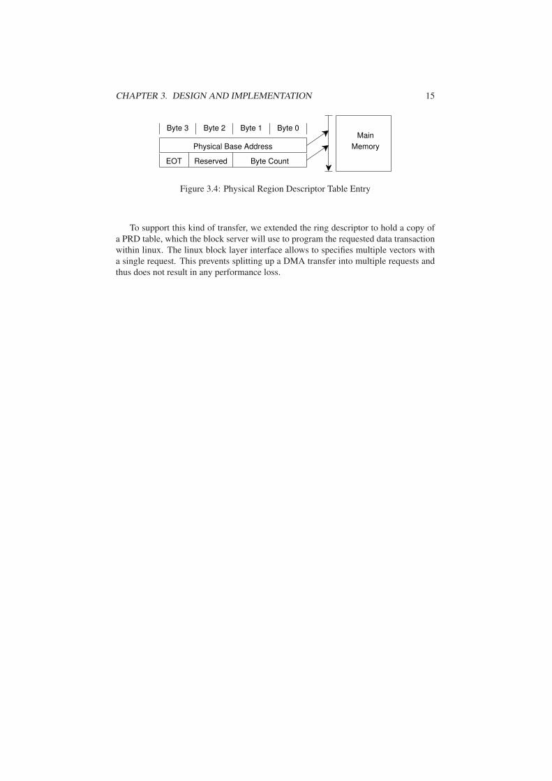
Physical Region Descriptor
The physical memory region to be transferred on a DMA transaction, is described
by a physical region descriptor (PRD) as shown in figure 3.4. The PRDs are stored
sequentially in a descriptor table in memory. Each PRD entry is 8 bytes in length. The
first 4 bytes specify the base address of a physical memory region, the next 2 specify
the size or transfer count of the region, and bit 7 (EOT) in the last byte indicates if this
is the final PRD in the descriptor table. The guest prepares this PRD table in memory
and provides the starting address by loading the PRD table pointer register prior to
engaging the buster master function.
CHAPTER 3. DESIGN AND IMPLEMENTATION 15
Byte 0Byte 1Byte 2Byte 3
EOT
Physical Base Address
Reserved Byte Count
Main
Memory
Figure 3.4: Physical Region Descriptor Table Entry
To support this kind of transfer, we extended the ring descriptor to hold a copy of
a PRD table, which the block server will use to program the requested data transaction
within linux. The linux block layer interface allows to specifies multiple vectors with
a single request. This prevents splitting up a DMA transfer into multiple requests and
thus does not result in any performance loss.
Chapter 4
Evaluation
In this chapter I will first give an overview about the different operating systems which
have successfully been booted. The next chapter gives an evaluation of the performance
achieved by using the emulated hard disk driver in both PIO-only and DMA mode. All
tests were performed on an Intel-VT CPU with 3.6 GHz and 2GB RAM. The used
hard disk drive was a Maxtor STM3802110A with 80GB, 2MB cache, UDMA 100
interface, connected to a Promise Ultra 133 TX2 controller.
In tests involving the hard disk, the VMM runs one instance of the DD/OS with
passthrough access to hardware devices and one instance of the guest with emulated
devices. In all other cases, we run only a single instance of the guest with passthrough
access.
4.1 Booting
In this section I will give an overview about which systems we are now able to boot
with the help of a virtual BIOS.
FreeDOS
The VMM successfully boots a previous installed 16-bit FreeDOS 1.0 [11] from hard-
disk. The command prompt is fully usable over the keyboard and the user can start
arbitrary system programs. Additionally it is possible to run OpenGEM, a graphical
user interface (GUI) and application set similar to Win 3.x from Microsoft. Because of
a missing emulated graphic card, GEM uses a VESA screen driver for output, which
allows a resolution of 800x600 (SVGA) and writes its output directly into the frame-
buffer.
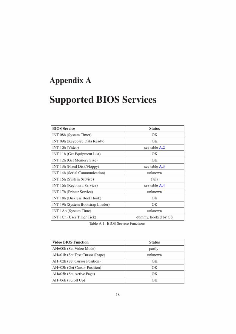
FreeDOS and other 16-Bit operating systems depend a lot from BIOS services,
appendix A lists the most important ones, that have been tested and are known to work.
Windows XP
We have made some effort to start an already installed Microsoft Windows XP. After
initial problems regarding the execution environment, we were able to start Windows
at least partially. At first we tried to start Windows with only emulated software inter-
rupts. After some time during system initialization, Windows tried to restart the sys-
tem. We believe that this is caused by missing configuration tables in memory, which
16

CHAPTER 4. EVALUATION 17
are normally established during system startup by the BIOS. Using an emulated BIOS
resolved this issue. At the moment Windows starts up to the boot menu, where you
can select different boot methods, like safe mode or debug mode. Continuing startup
results in Windows setting up debug register, which is currently not handled by the VM
monitor. Further work has to be done to fully support Windows as a guest.
4.2 Hard Disk Drive
Starting
The VMM starts successfully FreeDOS, Linux and parts of Windows XP from an emu-
lated hard disk. The main difference between FreeDOS and all other operating systems
is, that it does not use interrupts to signal command completion. Hosts can disable in-
terrupt delivery, by writing a 1 to bit 1 in the device control register. They have to poll
the status register instead, and wait for busy to become 0, which indicates command
completion. While Linux boots with both, the generic IDE controller and the DMA
controller, FreeDOS and Windows use only the generic part, because FreeDOS and
this early stage of Windows use only BIOS services, that don’t support DMA transfers.
Performance
The following gives an overview of the results of benchmarking the emulated hard
disk as well as a short evaluation of the results. Table 4.1 shows the performance of
sequential data reads (bursts) under a linux guest, without any filesystem overhead,
compared to the results on native hardware. To test PIO mode, the hard disk drive was
forced with hdparm to disable DMA transfers.
Native [MB/s] VM [MB/s]
PIO mode 1.9389 2.7976
DMA mode 60.0213 5.5950
Table 4.1: Sequential read of 8KB blocks from hard disk
The curiosity in PIO mode, that the VM is faster than the native hardware, is caused
by the fact that the DD/OS actually uses DMA to transfer the requested block into the
VMM’s local cache.
The problem causing this massive performance loss on DMA transfers results pri-
marily from the DD/OS linux. Tests have shown that the major amount of time was
spend in linux waiting for the request to complete. A single request took about 18.86ms
on average, whereas about 2.16ms resulted from emulation and signaling in the VMM
and 2.68ms from overhead in the block server. The remaining 14.02ms was the average
time needed to complete the request within linux. According to the ATA specification,
a host can request up to 256 sectors with a single read command, which is exactly
128KB. Even if linux would always request a maximum sector number, it would still
result in only about 9.129 MB/s throughput. Compared to the potential native perfor-
mance, the DD/OS is much too slow. We suspect that this may be caused by scheduling
effects.
Appendix A
Supported BIOS Services
BIOS Service Status
INT 08h (System Timer) OK
INT 09h (Keyboard Data Ready) OK
INT 10h (Video) see table A.2
INT 11h (Get Equipment List) OK
INT 12h (Get Memory Size) OK
INT 13h (Fixed Disk/Floppy) see table A.3
INT 14h (Serial Communication) unknown
INT 15h (System Service) fails
INT 16h (Keyboard Service) see table A.4
INT 17h (Printer Service) unknown
INT 18h (Diskless Boot Hook) OK
INT 19h (System Bootstrap Loader) OK
INT 1Ah (System Time) unknown
INT 1Ch (User Timer Tick) dummy, hooked by OS
Table A.1: BIOS Service Functions
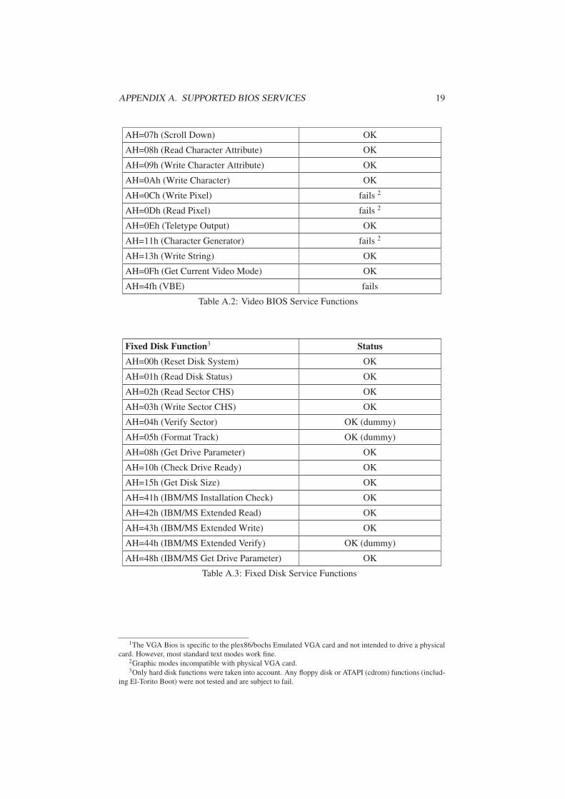
Video BIOS Function Status
AH=00h (Set Video Mode) partly1
AH=01h (Set Text Cursor Shape) unknown
AH=02h (Set Cursor Position) OK
AH=03h (Get Cursor Position) OK
AH=05h (Set Active Page) OK
AH=06h (Scroll Up) OK
18
APPENDIX A. SUPPORTED BIOS SERVICES 19
AH=07h (Scroll Down) OK
AH=08h (Read Character Attribute) OK
AH=09h (Write Character Attribute) OK
AH=0Ah (Write Character) OK
AH=0Ch (Write Pixel) fails 2
AH=0Dh (Read Pixel) fails 2
AH=0Eh (Teletype Output) OK
AH=11h (Character Generator) fails 2
AH=13h (Write String) OK
AH=0Fh (Get Current Video Mode) OK
AH=4fh (VBE) fails
Table A.2: Video BIOS Service Functions
Fixed Disk Function3 Status
AH=00h (Reset Disk System) OK
AH=01h (Read Disk Status) OK
AH=02h (Read Sector CHS) OK
AH=03h (Write Sector CHS) OK
AH=04h (Verify Sector) OK (dummy)
AH=05h (Format Track) OK (dummy)
AH=08h (Get Drive Parameter) OK
AH=10h (Check Drive Ready) OK
AH=15h (Get Disk Size) OK
AH=41h (IBM/MS Installation Check) OK
AH=42h (IBM/MS Extended Read) OK
AH=43h (IBM/MS Extended Write) OK
AH=44h (IBM/MS Extended Verify) OK (dummy)
AH=48h (IBM/MS Get Drive Parameter) OK
Table A.3: Fixed Disk Service Functions
1The VGA Bios is specific to the plex86/bochs Emulated VGA card and not intended to drive a physical
card. However, most standard text modes work fine.2Graphic modes incompatible with physical VGA card.3Only hard disk functions were taken into account. Any floppy disk or ATAPI (cdrom) functions (includ-
ing El-Torito Boot) were not tested and are subject to fail.

APPENDIX A. SUPPORTED BIOS SERVICES 20
Keyboard Function Status
AH=00h (Read Keyboard) OK
AH=01h (Check Status) OK
AH=02h (Get Shift Flag Status) OK
AH=05h (Store Keystroke) unknown
AH=0Ah (Get Keyboard ID) OK
AH=10h (MF-II Read Keyboard) unknown
AH=11h (MF-II Check Status) unknown
AH=12h (MF-II Get Extended Status) unknown
Table A.4: Keyboard Service Functions
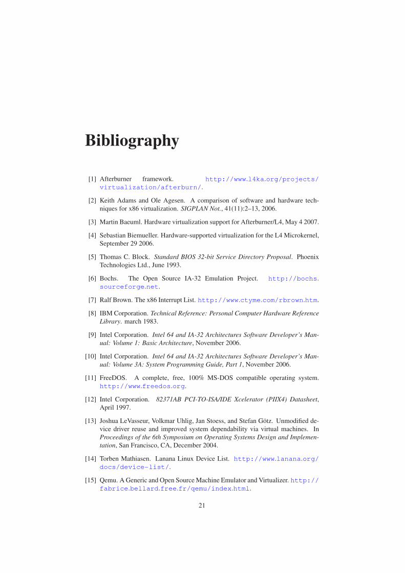
Bibliography
[1] Afterburner framework. http://www.l4ka.org/projects/
virtualization/afterburn/.
[2] Keith Adams and Ole Agesen. A comparison of software and hardware tech-
niques for x86 virtualization. SIGPLAN Not., 41(11):2–13, 2006.
[3] Martin Baeuml. Hardware virtualization support for Afterburner/L4, May 4 2007.
[4] Sebastian Biemueller. Hardware-supported virtualization for the L4 Microkernel,
September 29 2006.
[5] Thomas C. Block. Standard BIOS 32-bit Service Directory Proposal. Phoenix
Technologies Ltd., June 1993.
[6] Bochs. The Open Source IA-32 Emulation Project. http://bochs.
sourceforge.net.
[7] Ralf Brown. The x86 Interrupt List. http://www.ctyme.com/rbrown.htm.
[8] IBM Corporation. Technical Reference: Personal Computer Hardware Reference
Library. march 1983.
[9] Intel Corporation. Intel 64 and IA-32 Architectures Software Developer’s Man-
ual: Volume 1: Basic Architecture, November 2006.
[10] Intel Corporation. Intel 64 and IA-32 Architectures Software Developer’s Man-
ual: Volume 3A: System Programming Guide, Part 1, November 2006.
[11] FreeDOS. A complete, free, 100% MS-DOS compatible operating system.
http://www.freedos.org.
[12] Intel Corporation. 82371AB PCI-TO-ISA/IDE Xcelerator (PIIX4) Datasheet,
April 1997.
[13] Joshua LeVasseur, Volkmar Uhlig, Jan Stoess, and Stefan Gotz. Unmodified de-
vice driver reuse and improved system dependability via virtual machines. In
Proceedings of the 6th Symposium on Operating Systems Design and Implemen-
tation, San Francisco, CA, December 2004.
[14] Torben Mathiasen. Lanana Linux Device List. http://www.lanana.org/
docs/device-list/.
[15] Qemu. A Generic and Open Source Machine Emulator and Virtualizer. http://
fabrice.bellard.free.fr/qemu/index.html.
21
BIBLIOGRAPHY 22
[16] Adam Sulmicki. A Study of BIOS Services as used by Microsoft Windows XP.
http://www.missl.cs.umd.edu/winint/index2.html.
[17] T13. Information Technology - AT Attachment with Packet Interface - 6
(ATA/ATAPI-6), February 2002.
[18] Xen. Open Source Hypervisor. http://www.xensource.com.