leed for core and shell
TRANSCRIPT

LEED® Green Building Rating System™ For Core & Shell Development
Version 2.0
July 2006*
For Public Use and Display
*Revised EA section for projects registered after June 26, 2007.

LEED for Core & Shell Version 2, July 2006 - Revised EA section for projects registered after June 26, 2007
Page 1
Disclaimer and Notices The U.S. Green Building Council authorizes you to view the LEED for Core & Shell Green Building Rating System for your individual use and to copy as-is, or in part if you reference the original document. No content may be altered. In exchange for this authorization, you agree to retain all copyright and other proprietary notices contained in the original LEED for Core & Shell Green Building Rating System. You also agree not to sell or modify the LEED for Core & Shell Green Building Rating System or to reproduce, display or distribute the LEED for Core & Shell Green Building Rating System in any way for any public or commercial purpose, including display on a website or in a networked environment. Unauthorized use of the LEED for Core & Shell Green Building Rating System violates copyright, trademark and other laws and is prohibited. All text, graphics, layout and other elements of content contained in the LEED for Core & Shell Green Building Rating System are owned by the U.S. Green Building Council and are protected by copyright under both United States and foreign laws. Also, please note that none of the parties involved in the funding or creation of the LEED for Core & Shell Green Building Rating System, including the U.S. Green Building Council or its members, make any warranty (express or implied) or assume any liability or responsibility, to you or any third parties for the accuracy, completeness, or use of, or reliance on, any information contained in the LEED for Core & Shell Green Building Rating System, or for any injuries, losses or damages (including, without limitation, equitable relief) arising out of such use or reliance. As a condition of use, you covenant not to sue, and agree to waive and release the U.S. Green Building Council and its members from any and all claims, demands and causes of action for any injuries, losses or damages (including, without limitation, equitable relief) that you may now or hereafter have a right to assert against such parties as a result of your use of, or reliance on, the LEED for Core & Shell Green Building Rating System. Copyright Copyright © 2006 by the U.S. Green Building Council. All rights reserved. Trademark LEED® is a registered trademark of the U.S. Green Building Council.

LEED for Core & Shell Version 2, July 2006 - Revised EA section for projects registered after June 26, 2007
Page 2
Table of Contents INTRODUCTION 4
PROJECT CHECKLIST 9
SUSTAINABLE SITES 11 SS Prerequisite 1: Construction Activity Pollution Prevention .................................... 11 SS Credit 1: Site Selection .............................................................................. 12 SS Credit 2: Development Density & Community Connectivity ................................... 13 SS Credit 3: Brownfield Redevelopment.............................................................. 14 SS Credit 4.1: Alternative Transportation: Public Transportation Access ....................... 15 SS Credit 4.2: Alternative Transportation: Bicycle Storage & Changing Rooms ................ 16 SS Credit 4.3: Alternative Transportation: Low Emitting & Fuel Efficient Vehicles ........... 17 SS Credit 4.4: Alternative Transportation: Parking Capacity...................................... 18 SS Credit 5.1: Site Development: Protect or Restore Habitat..................................... 19 SS Credit 5.2: Site Development: Maximize Open Space........................................... 20 SS Credit 6.1: Stormwater Design: Quantity Control ............................................... 21 SS Credit 6.2: Stormwater Design: Quality Control ................................................. 22 SS Credit 7.1: Heat Island Effect: Non-Roof ......................................................... 23 SS Credit 7.2: Heat Island Effect: Roof ............................................................... 24 SS Credit 8: Light Pollution Reduction ................................................................ 25 SS Credit 9: Tenant Design & Construction Guidelines ............................................. 27
WATER EFFICIENCY 29 WE Credit 1.1: Water Efficient Landscaping: Reduce by 50% ..................................... 29 WE Credit 1.2: Water Efficient Landscaping: No Potable Water Use or No Irrigation......... 30 WE Credit 2: Innovative Wastewater Technologies ................................................. 31 WE Credit 3.1: Water Use Reduction: 20% Reduction .............................................. 32 WE Credit 3.2: Water Use Reduction: 30% Reduction .............................................. 33
ENERGY & ATMOSPHERE 34 EA Prerequisite 1: Fundamental Commissioning of the Building Energy Systems .............. 34 EA Prerequisite 2: Minimum Energy Performance................................................... 36 EA Prerequisite 3: Fundamental Refrigerant Management ........................................ 37 EA Credit 1: Optimize Energy Performance (revised for projects registered after June 26, 2007) ............ 38 EA Credit 2: On-Site Renewable Energy .............................................................. 41 EA Credit 3: Enhanced Commissioning................................................................ 42 EA Credit 4: Enhanced Refrigerant Management.................................................... 44 EA Credit 5.1: Measurement & Verification- Base Building........................................ 46 EA Credit 5.2 Measurement and Verification – Tenant Sub-metering............................ 47

LEED for Core & Shell Version 2, July 2006 - Revised EA section for projects registered after June 26, 2007
Page 3
EA Credit 6: Green Power............................................................................... 48 MATERIALS & RESOURCES 49
MR Prerequisite 1: Storage & Collection of Recyclables ........................................... 49 MR Credit 1.1: Building Reuse: Maintain 25%, of Existing Walls, Floors & Roof ................ 50 MR Credit 1.2: Building Reuse: Maintain 50%, of Existing Walls, Floors & Roof ................ 51 MR Credit 1.3: Building Reuse: Maintain 75%, of Existing Walls, Floors & Roof ................ 52 MR Credit 2.1: Construction Waste Management: Divert 50% From Disposal ................... 53 MR Credit 2.2: Construction Waste Management: Divert 75% From Disposal ................... 54 MR Credit 3: Materials Reuse: 1% ...................................................................... 55 MR Credit 4.1: Recycled Content: 10% (post-consumer + 1/2 pre-consumer) .................. 56 MR Credit 4.2: Recycled Content: 20% (post-consumer + 1/2 pre-consumer) .................. 57 MR Credit 5.1: Regional Materials: 10% Extracted, Processed & Manufactured Regionally .. 58 MR Credit 5.2: Regional Materials: 20% Extracted, Processed & Manufactured Regionally .. 59 MR Credit 6: Certified Wood............................................................................ 60
INDOOR ENVIRONMENTAL QUALITY 61 EQ Prerequisite 1: Minimum IAQ Performance ...................................................... 61 EQ Prerequisite 2: Environmental Tobacco Smoke (ETS) Control ................................ 62 EQ Credit 1: Outdoor Air Delivery Monitoring ....................................................... 64 EQ Credit 2: Increased Ventilation .................................................................... 65 EQ Credit 3: Construction IAQ Management Plan: During Construction ......................... 66 EQ Credit 4.1: Low-Emitting Materials: Adhesives & Sealants .................................... 67 EQ Credit 4.2: Low-Emitting Materials: Paints & Coatings ........................................ 69 EQ Credit 4.3: Low-Emitting Materials: Carpet Systems ........................................... 70 EQ Credit 4.4: Low-Emitting Materials: Composite Wood & Agrifiber Products................ 71 EQ Credit 5: Indoor Chemical & Pollutant Source Control......................................... 72 EQ Credit 6: Controllability of Systems: Thermal Comfort ........................................ 73 EQ Credit 7: Thermal Comfort: Design................................................................ 74 EQ Credit 8.1: Daylight & Views: Daylight 75% of Spaces.......................................... 75 EQ Credit 8.2: Daylight & Views: Views for 90% of Spaces ........................................ 78
INNOVATION & DESIGN PROCESS 79 ID Credit 1–1.4: Innovation in Design.................................................................. 79 ID Credit 2: LEED Accredited Professional ........................................................... 80
APPENDIX 1 – DEFAULT OCCUPANCY COUNTS 81
APPENDIX 2 – CORE AND SHELL ENERGY MODELING GUIDELINES 82
APPENDIX 3 – LEED FOR CORE & SHELL PROJECT SCOPE CHECKLIST 84

LEED for Core & Shell Version 2, July 2006 - Revised EA section for projects registered after June 26, 2007
Page 4
Introduction The Leadership in Energy and Environmental Design (LEED®) Green Building Rating System for Core & Shell Development (LEED for Core & Shell) is a set of performance criteria for certifying the sustainable design and construction of speculative and core and shell buildings. It has been developed as part of the U.S. Green Building Council’s ongoing effort to provide a national standard for what constitutes a “green building.” The intent of which is to assist in the creation of high performance, healthful, durable, affordable and environmentally sound buildings. The LEED for Core & Shell Rating System is a market specific application, which recognizes the unique nature of core and shell development. The Rating System acknowledges the limited sphere of influence over which a developer can exert control in a speculatively developed building and encourages the implementation of green design and construction practices in areas where the developer has control. LEED for Core & Shell works to set up a synergistic relationship, which allows future tenants to capitalize on green strategies implemented by the developer. Some key building areas, interior space layout, interior finishes, lighting, mechanical distribution, and other tenant related systems are often outside the direct control of the developer. Thus, the scope of a LEED for Core & Shell project is limited to those aspects of the project over which the developer has direct control. It is the responsibility of the developer/owner to properly identify which LEED rating system to use for the LEED building certification as further described herein. LEED for Core & Shell is designed to be complementary to the LEED for Commercial Interiors Green Building Rating System (LEED-CI). The LEED-CI and LEED for Core & Shell rating systems establish green building criteria for both developer/owners and tenants. LEED for Core & Shell addresses: • Site selection; • Water efficiency in core and shell building systems; • Energy optimization of the core and shell systems and provisions for fit out of tenant spaces to optimize operational building energy use; • Materials and resource guidelines for construction of building core and shell;
• Indoor Environmental Quality planning of the building core and shell to ensure tenant fit out is able to make optimal use of Indoor Environmental Quality attributes including thermal comfort, daylight, and views as well as prevention of contamination from indoor pollutants.

LEED for Core & Shell Version 2, July 2006 - Revised EA section for projects registered after June 26, 2007
Page 5
DEFINING THE CORE & SHELL BUILDING The LEED for Core & Shell Rating System provides the building design and construction industry with a LEED rating system that serves the speculatively driven development market where project teams routinely do not control all aspects of a building’s design and construction. The scope of LEED for Core & Shell is limited to those elements of the project under the direct control of the developer/owner. Depending on how the project is structured, this scope can range greatly from project to project. The LEED for Core & Shell Rating System has been developed to address a variety of project types and a broad project scope range. Scope of Construction
• LEED for Core & Shell can be used for projects where the developer controls the design and construction of the entire core and shell base building including MEP/FP systems, but have no control over the design and construction of the tenant fit-out. An example of this type of project is a commercial office building, medical office building, retail center, warehouse, or lab facility.
• LEED for Core & Shell can also be used for projects that have limited control of
the building systems. This is often found in retail development. Projects with limited scope should review the specific credit requirements for guidance.
• In projects that are designed and constructed to be partially occupied by the
owner/developer, there is clearly the ability of the owner/developer to directly influence the portion of the work that would typically be tenant interior construction. For projects of this type to utilize the LEED for Core & Shell Rating System, the owner/tenant must occupy 50% or less of the building’s leasable space. Projects with greater than 50% of the building’s tenant space occupied by a tenant/owner should utilize LEED-NC.
Core & Shell and Tenant Space Guidance To assist project teams in defining the tenant/owner division in both the project design as well as certification review process, the Core & Shell / Tenant Interiors Checklist has been developed. This checklist is attached as Appendix 3.

LEED for Core & Shell Version 2, July 2006 - Revised EA section for projects registered after June 26, 2007
Page 6
LEED for Core & Shell Pre-certification Overview LEED for Core & Shell pre-certification is a unique aspect of the LEED for Core & Shell program. Pre-certification is formal recognition by USGBC given to a LEED for Core & Shell candidate project for which the developer/owner has established a goal to develop a LEED for Core & Shell building. LEED for Core & Shell pre-certification is granted to projects after USGBC has reviewed early design stage documentation. This documentation, which reflects a studied and realistic set of project goals and intentions, forms the basis for an award of pre-certification at the project’s anticipated LEED for Core & Shell certification level. Pre-certification is not a documented and completed building and is not confirmation or a commitment to achieve LEED for Core & Shell certification. Pre-certification is not LEED Certification. Value Pre-certification provides the core & shell developer/owner with the ability to market to potential tenants and financiers the unique and valuable green features of a proposed building. Submittal and Review Once a project is registered as a LEED for Core & Shell project with USGBC, the project team may complete the LEED for Core & Shell pre-certification letter templates and submit the project for pre-certification. This is a voluntary submittal at the discretion of the project team. Because much of the value of pre-certification occurs early in a project’s development, the project team’s documentation and USGBC’s review is less comprehensive than the final LEED for Core & Shell certification application. Project teams are required to provide confirmation that the project intends to meet the requirements of a credit. This is provided using the LEED for Core & Shell pre-certification letter templates on the appropriate design team member’s letterhead for each credit pursued, with a brief description of the strategy and/or technology that will be employed. The developer/owner is also required to provide a signed letter template declaring that they are in agreement with the intention and strategies as indicated on each credit specific letter template submitted. The LEED for Core & Shell Project Scope checklist will also need to be submitted. This checklist is both a design team tool and provides USGBC with useful building information for the review. This includes information about building use, LEED for Core & Shell occupancy numbers and core and shell scope. The project is reviewed and a LEED for Core & Shell pre-certification level (certified, silver, gold or platinum) is granted. A certificate and letter are provided to the project. The review will allow the developer to market the project’s intention to achieve a particular LEED for Core & Shell certification level. This pre-certification process is not intended to be a supplementary comprehensive review of a project’s submittal and the

LEED for Core & Shell Version 2, July 2006 - Revised EA section for projects registered after June 26, 2007
Page 7
anticipated LEED for Core & Shell certification level. LEED for Core & Shell certification review will still occur with USGBC’s established two-phase application (Design and Construction). Because of the many factors inherent in project design, construction and project documentation and review, it is possible that the final certification review will not correspond exactly to the pre-certification review. Project team members should be aware that it is incumbent upon the team to demonstrate that the credit requirements have been met at the design and construction certification reviews.

LEED for Core & Shell Version 2, July 2006 - Revised EA section for projects registered after June 26, 2007
Page 8
Credit Compliance Overview The LEED for Core & Shell Rating System is written for core and shell development and is intentionally neutral regarding requirements for tenant build-out. A LEED for Core & Shell rating can be attained without making any requirements of a tenant. A tenant can choose to pursue or not to pursue a LEED for Commercial Interiors (LEED-CI) rating with no impact on the building’s LEED for Core & Shell rating. However, if a developer chooses to make specific lease requirements part of their tenant negotiation, and these requirements meet the criteria of a particular credit in the LEED for Core & Shell Rating System, the LEED for Core & Shell project may be able to receive a point for this credit even if the work is not part of the core and shell design and construction. The following describes this approach to credit compliance and may be used, as applicable, throughout the rating system. Requirements Meet LEED for Core & Shell Credit requirements through either;
• Design and construction of the building core and shell, OR • Establishment of tenant requirements that meet the LEED for Core & Shell credit
requirements, but will be implemented as part of the tenant controlled build-out. Submittals
• Provide the LEED letter template, signed by the building developer/owner for the credit being pursued, based on the core and shell design and construction.
OR • The LEED letter template for the credit pursued indicating that:
- 100% of leased square footage complies with credit requirements. Lease or sales agreements may be requested. AND - That 100% of the unleased square footage shall comply with the credit requirements when leased. A statement signed by the developer/owner that all leases and/or sales agreements will comply may be requested.
USGBC recognizes the realities and complexity of tenant fit out and the difficulties associated with the enforcement of a 100% compliance path requirement. As result, in certain instances, a minor portion of the final fully occupied tenant spaces may not meet the 100% requirement. Under such a situation, the committee acknowledges the 100% assurance as being met. Minor portion is defined as a 10% variance.
LEED for Core & Shell Version 2, July 2006 - Revised EA section for projects registered after June 26, 2007
Page 9
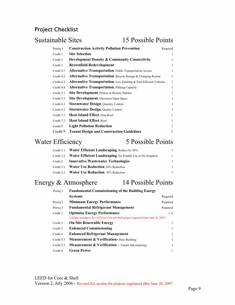
Project Checklist
Sustainable Sites 15 Possible Points Prereq 1 Construction Activity Pollution Prevention Required Credit 1 Site Selection 1 Credit 2 Development Density & Community Connectivity 1 Credit 3 Brownfield Redevelopment 1 Credit 4.1 Alternative Transportation, Public Transportation Access 1 Credit 4.2 Alternative Transportation, Bicycle Storage & Changing Rooms 1 Credit 4.3 Alternative Transportation, Low Emitting & Fuel Efficient Vehicles 1 Credit 4.4 Alternative Transportation, Parking Capacity 1 Credit 5.1 Site Development, Protect or Restore Habitat 1 Credit 5.2 Site Development, Maximize Open Space 1 Credit 6.1 Stormwater Design, Quantity Control 1 Credit 6.2 Stormwater Design, Quality Control 1 Credit 7.1 Heat Island Effect, Non-Roof 1 Credit 7.2 Heat Island Effect, Roof 1 Credit 8 Light Pollution Reduction 1
Credit 9 Tenant Design and Construction Guidelines 1
Water Efficiency 5 Possible Points Credit 1.1 Water Efficient Landscaping, Reduce by 50% 1 Credit 1.2 Water Efficient Landscaping, No Potable Use or No Irrigation 1 Credit 2 Innovative Wastewater Technologies 1 Credit 3.1 Water Use Reduction, 20% Reduction 1 Credit 3.2 Water Use Reduction, 30% Reduction 1
Energy & Atmosphere 14 Possible Points Prereq 1 Fundamental Commissioning of the Building Energy Systems Required Prereq 2 Minimum Energy Performance Required Prereq 3 Fundamental Refrigerant Management Required Credit 1 Optimize Energy Performance 1–8 (2 points mandatory for LEED for Core and Shell projects registered after June 26, 2007) Credit 2 On-Site Renewable Energy 1 Credit 3 Enhanced Commissioning 1 Credit 4 Enhanced Refrigerant Management 1 Credit 5.1 Measurement & Verification- Base Building 1
Credit 5.2 Measurement & Verification – Tenant Sub-metering 1 Credit 6 Green Power 1

LEED for Core & Shell Version 2, July 2006 - Revised EA section for projects registered after June 26, 2007
Page 10
Materials & Resources 11 Possible Points Prereq 1 Storage & Collection of Recyclables Required Credit 1.1 Building Reuse, Maintain 25% of Existing Walls, Floors & Roof 1 Credit 1.2 Building Reuse, Maintain 50% of Existing Walls, Floors & Roof 1 Credit 1.3 Building Reuse, Maintain 75% of Existing Walls, Floors & Roof 1 Credit 2.1 Construction Waste Management, Divert 50% from Disposal 1 Credit 2.2 Construction Waste Management, Divert 75% from Disposal 1 Credit 3 Materials Reuse, 1% 1 Credit 4.1 Recycled Content, 10% (post-consumer + 1/2 pre-consumer) 1 Credit 4.2 Recycled Content, 20% (post-consumer + 1/2 pre-consumer) 1 Credit 5.1 Regional Materials, 10% Extracted, Processed & Manufactured Regionally 1
Credit 5.2 Regional Materials, 20% Extracted, Processed & Manufactured Regionally 1
Credit 6 Certified Wood 1
Indoor Environmental Quality 11 Possible Points Prereq 1 Minimum IAQ Performance Required Prereq 2 Environmental Tobacco Smoke (ETS) Control Required Credit 1 Outdoor Air Delivery Monitoring 1 Credit 2 Increased Ventilation 1 Credit 3 Construction IAQ Management Plan, During Construction 1 Credit 4.1 Low-Emitting Materials, Adhesives & Sealants 1 point for 2 Credit 4.2 Low-Emitting Materials, Paints & Coatings 2 points for 3 Credit 4.3 Low-Emitting Materials, Carpet Systems 3 points for 4 Credit 4.4 Low-Emitting Materials, Composite Wood & Agrifiber Products Credit 5 Indoor Chemical & Pollutant Source Control 1 Credit 6 Controllability of Systems, Thermal Comfort 1 Credit 7 Thermal Comfort, Design 1 Credit 8.1 Daylight & Views, Daylight 75% of Spaces 1 Credit 8.2 Daylight & Views, Views for 90% of Spaces 1
Innovation & Design Process 5 Possible Points Credit 1.1 Innovation in Design 1 Credit 1.2 Innovation in Design 1 Credit 1.3 Innovation in Design 1 Credit 1.4 Innovation in Design 1 Credit 2 LEED Accredited Professional 1
Project Totals 61 Possible Points Certified 23–27 points Silver 28–33 points Gold 34–44 points Platinum 45–61 points
LEED for Core & Shell Version 2, July 2006 - Revised EA section for projects registered after June 26, 2007
Page 11
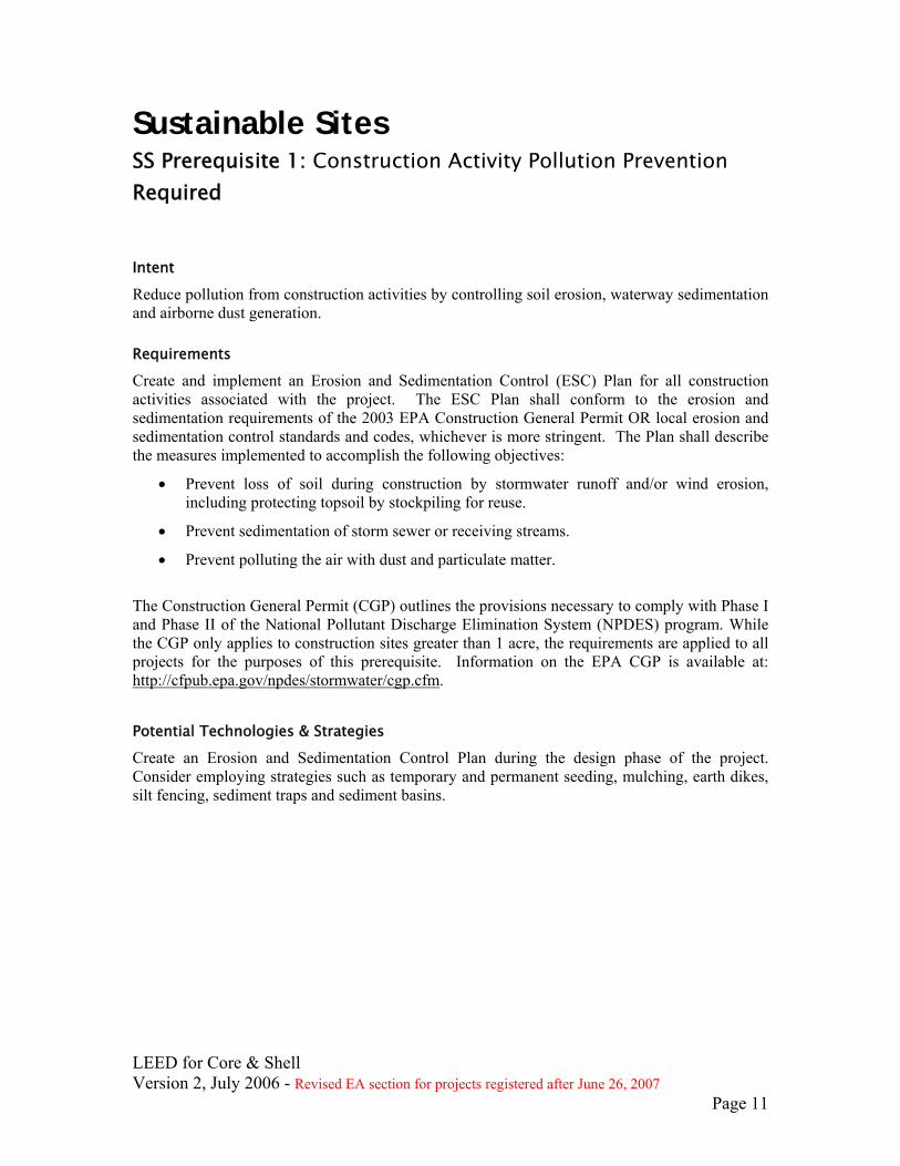
Sustainable Sites SS Prerequisite 1: Construction Activity Pollution Prevention Required
Intent
Reduce pollution from construction activities by controlling soil erosion, waterway sedimentation and airborne dust generation.
Requirements
Create and implement an Erosion and Sedimentation Control (ESC) Plan for all construction activities associated with the project. The ESC Plan shall conform to the erosion and sedimentation requirements of the 2003 EPA Construction General Permit OR local erosion and sedimentation control standards and codes, whichever is more stringent. The Plan shall describe the measures implemented to accomplish the following objectives:
• Prevent loss of soil during construction by stormwater runoff and/or wind erosion, including protecting topsoil by stockpiling for reuse.
• Prevent sedimentation of storm sewer or receiving streams.
• Prevent polluting the air with dust and particulate matter.
The Construction General Permit (CGP) outlines the provisions necessary to comply with Phase I and Phase II of the National Pollutant Discharge Elimination System (NPDES) program. While the CGP only applies to construction sites greater than 1 acre, the requirements are applied to all projects for the purposes of this prerequisite. Information on the EPA CGP is available at: http://cfpub.epa.gov/npdes/stormwater/cgp.cfm.
Potential Technologies & Strategies
Create an Erosion and Sedimentation Control Plan during the design phase of the project. Consider employing strategies such as temporary and permanent seeding, mulching, earth dikes, silt fencing, sediment traps and sediment basins.
LEED for Core & Shell Version 2, July 2006 - Revised EA section for projects registered after June 26, 2007
Page 12
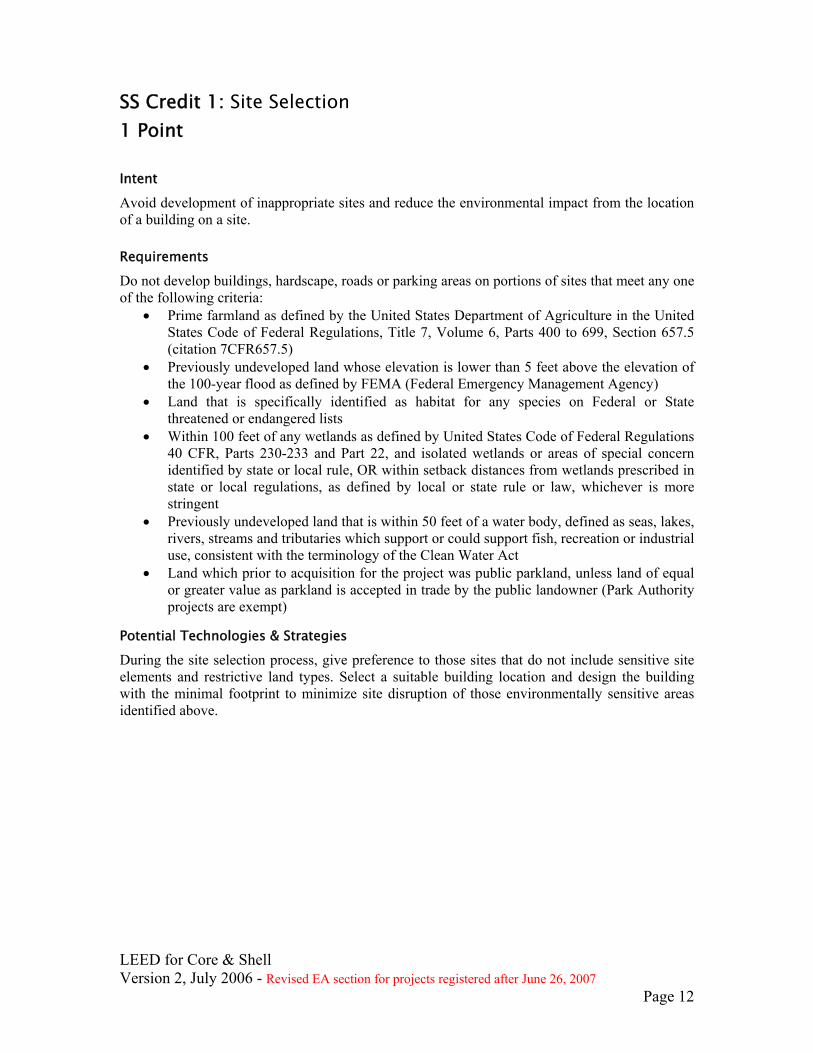
SS Credit 1: Site Selection 1 Point
Intent
Avoid development of inappropriate sites and reduce the environmental impact from the location of a building on a site.
Requirements
Do not develop buildings, hardscape, roads or parking areas on portions of sites that meet any one of the following criteria:
• Prime farmland as defined by the United States Department of Agriculture in the United States Code of Federal Regulations, Title 7, Volume 6, Parts 400 to 699, Section 657.5 (citation 7CFR657.5)
• Previously undeveloped land whose elevation is lower than 5 feet above the elevation of the 100-year flood as defined by FEMA (Federal Emergency Management Agency)
• Land that is specifically identified as habitat for any species on Federal or State threatened or endangered lists
• Within 100 feet of any wetlands as defined by United States Code of Federal Regulations 40 CFR, Parts 230-233 and Part 22, and isolated wetlands or areas of special concern identified by state or local rule, OR within setback distances from wetlands prescribed in state or local regulations, as defined by local or state rule or law, whichever is more stringent
• Previously undeveloped land that is within 50 feet of a water body, defined as seas, lakes, rivers, streams and tributaries which support or could support fish, recreation or industrial use, consistent with the terminology of the Clean Water Act
• Land which prior to acquisition for the project was public parkland, unless land of equal or greater value as parkland is accepted in trade by the public landowner (Park Authority projects are exempt)
Potential Technologies & Strategies
During the site selection process, give preference to those sites that do not include sensitive site elements and restrictive land types. Select a suitable building location and design the building with the minimal footprint to minimize site disruption of those environmentally sensitive areas identified above.

LEED for Core & Shell Version 2, July 2006 - Revised EA section for projects registered after June 26, 2007
Page 13
SS Credit 2: Development Density & Community Connectivity 1 Point
Intent
Channel development to urban areas with existing infrastructure, protect greenfields and preserve habitat and natural resources.
Requirements
OPTION 1 — DEVELOPMENT DENSITY
Construct or renovate building on a previously developed site AND in a community with a minimum density of 60,000 square feet per acre net (Note: density calculation must include the area of the project being built and is based on a typical two-story downtown development).
OR
OPTION 2 — COMMUNITY CONNECTIVITY
Construct or renovate building on a previously developed site AND within 1/2 mile of a residential zone or neighborhood with an average density of 10 units per acre net AND within 1/2 mile of at least 10 Basic Services AND with pedestrian access between the building and the services.
Basic Services include, but are not limited to:
1) Bank; 2) Place of Worship; 3) Convenience Grocery; 4) Day Care; 5) Cleaners; 6) Fire Station; 7) Beauty; 8) Hardware; 9) Laundry; 10) Library; 11) Medical/Dental; 12) Senior Care Facility; 13) Park; 14) Pharmacy; 15) Post Office; 16) Restaurant; 17) School; 18) Supermarket; 19) Theater; 20) Community Center; 21) Fitness Center; 22) Museum. Proximity is determined by drawing a 1/2 mile radius around the main building entrance on a site map and counting the services within that radius.
Potential Technologies & Strategies
During the site selection process, give preference to urban sites with pedestrian access to a variety of services.

LEED for Core & Shell Version 2, July 2006 - Revised EA section for projects registered after June 26, 2007
Page 14
SS Credit 3: Brownfield Redevelopment 1 Point
Intent
Rehabilitate damaged sites where development is complicated by environmental contamination, reducing pressure on undeveloped land.
Requirements
Develop on a site documented as contaminated (by means of an ASTM E1903-97 Phase II Environmental Site Assessment or a local Voluntary Cleanup Program) OR on a site defined as a brownfield by a local, state or federal government agency.
Potential Technologies & Strategies
During the site selection process, give preference to brownfield sites. Identify tax incentives and property cost savings. Coordinate site development plans with remediation activity, as appropriate.
LEED for Core & Shell Version 2, July 2006 - Revised EA section for projects registered after June 26, 2007
Page 15
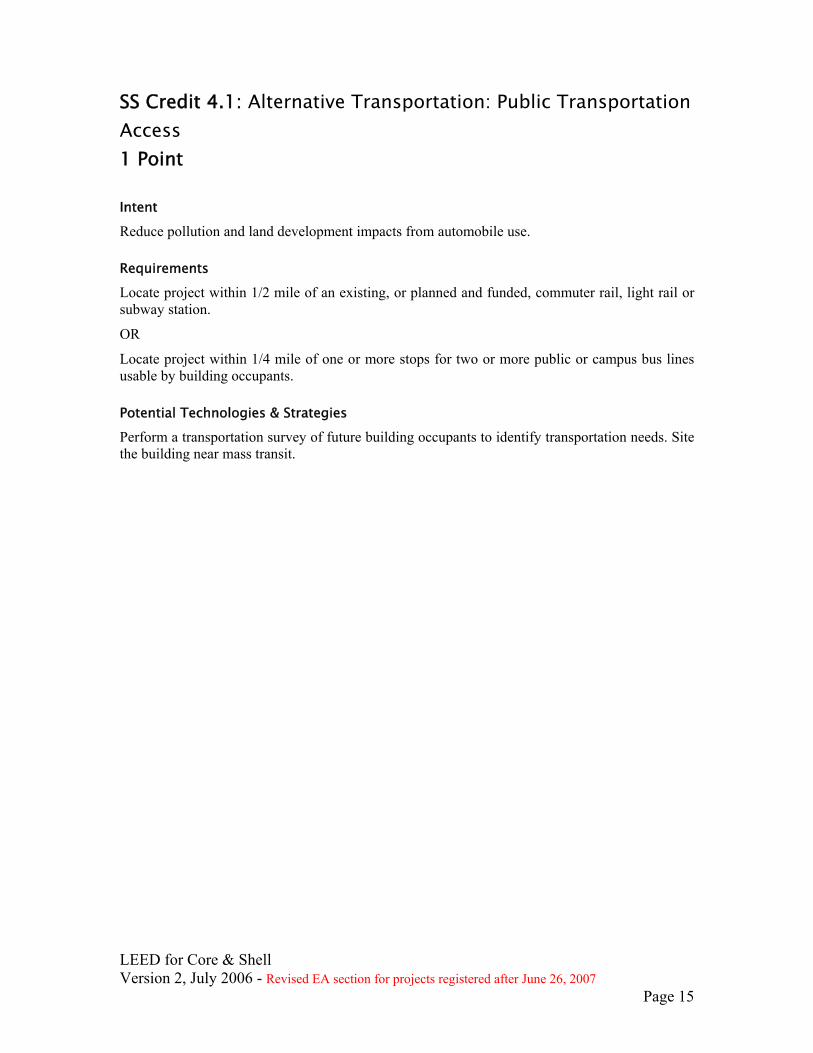
SS Credit 4.1: Alternative Transportation: Public Transportation Access 1 Point
Intent
Reduce pollution and land development impacts from automobile use.
Requirements
Locate project within 1/2 mile of an existing, or planned and funded, commuter rail, light rail or subway station.
OR
Locate project within 1/4 mile of one or more stops for two or more public or campus bus lines usable by building occupants.
Potential Technologies & Strategies
Perform a transportation survey of future building occupants to identify transportation needs. Site the building near mass transit.

LEED for Core & Shell Version 2, July 2006 - Revised EA section for projects registered after June 26, 2007
Page 16
SS Credit 4.2: Alternative Transportation: Bicycle Storage & Changing Rooms 1 Point
Intent
Reduce pollution and land development impacts from automobile use.
Requirements
CASE 1
For commercial or institutional buildings with a total gross square footage of less than 300,000 sq. feet, provide secure bicycle racks and/or storage (within 200 yards of a building entrance) for 3% or more of all building users (calculated on average for the year), AND, provide shower and changing facilities in the building, or within 200 yards of a building entrance, for 0.5% of Full-Time Equivalent (FTE) occupants.
CASE 2
For projects with a total gross square footage greater than 300,000 sq feet, provide secure bicycle storage for 3% of the occupants for up to 300,000 sf, then an additional 0. 5% for the occupants for the space over 300,000 sf. Mixed-use buildings with a total gross square footage greater than 300,000 sq feet must apply this calculation for each use in the building. AND, provide shower and changing facilities in the building, or within 200 yards of a building entrance, for 0.5% of Full-Time Equivalent (FTE) occupants.
CASE 3
For residential buildings or the residential portion of a mixed-use building, provide covered storage facilities for securing bicycles for 15% or more of building occupants in lieu of changing/shower facilities.
See Appendix 1 – Default Occupancy Counts for occupancy count requirements and guidance.
Potential Technologies & Strategies
Design the building with transportation amenities such as bicycle racks and showering/changing facilities.
LEED for Core & Shell Version 2, July 2006 - Revised EA section for projects registered after June 26, 2007
Page 17
SS Credit 4.3: Alternative Transportation: Low Emitting & Fuel Efficient Vehicles 1 Point
Intent
Reduce pollution and land development impacts from automobile use.
Requirements
OPTION 1
Provide preferred parking for low-emitting and fuel-efficient vehicles for 5% of the total vehicle parking capacity of the site.
OR
OPTION 2
Install alternative-fuel refueling stations for 3% of the total vehicle parking capacity of the site (liquid or gaseous fueling facilities must be separately ventilated or located outdoors).
For the purposes of this credit, low-emitting and fuel-efficient vehicles are defined as vehicles that are either classified as Zero Emission Vehicles (ZEV) by the California Air Resources Board or have achieved a minimum green score of 40 on the American Council for an Energy Efficient Economy (ACEEE) annual vehicle rating guide. “Preferred parking” generally refers to the parking spots that are closest to the main entrance of the project (exclusive of spaces designated for handicapped) or parking passes provided at a discounted price. For project types that demonstrate market barriers to the definition of “preferred parking closest to the main entrance”, alternatives to may be considered on a case-by-case basis. See Appendix 1 – Default Occupancy Counts for occupancy count requirements and guidance.
Potential Technologies & Strategies
Provide transportation amenities such as alternative fuel refueling stations. Consider sharing the costs and benefits of refueling stations with neighbors.

LEED for Core & Shell Version 2, July 2006 - Revised EA section for projects registered after June 26, 2007
Page 18
SS Credit 4.4: Alternative Transportation: Parking Capacity 1 Point
Intent
Reduce pollution and land development impacts from single occupancy vehicle use.
Requirements
OPTION 1 — NON-RESIDENTIAL
• Size parking capacity to not exceed, minimum local zoning requirements.
OR
OPTION 2 — NON-RESIDENTIAL
For projects that provide parking for less than 3% of FTE building occupants:
• Provide preferred parking for carpools or vanpools, marked as such, for 3% of total provided parking spaces. OR
OPTION 2 — RESIDENTIAL
• Size parking capacity to not exceed minimum local zoning requirements, AND, provide infrastructure and support programs to facilitate shared vehicle usage such as carpool drop-off areas, designated parking for vanpools, or car-share services, ride boards, and shuttle services to mass transit.
OR
OPTION 3 — ALL
Provide no new parking. See Appendix 1 – Default Occupancy Counts for occupancy count requirements and guidance.
Potential Technologies & Strategies
Minimize parking lot/garage size. Consider sharing parking facilities with adjacent buildings. Consider alternatives that will limit the use of single occupancy vehicles.
LEED for Core & Shell Version 2, July 2006 - Revised EA section for projects registered after June 26, 2007
Page 19
SS Credit 5.1: Site Development: Protect or Restore Habitat 1 Point
Intent
Conserve existing natural areas and restore damaged areas to provide habitat and promote biodiversity.
Requirements
On greenfield sites, limit all site disturbance to 40 feet beyond the building perimeter; 10 feet beyond surface walkways, patios, surface parking and utilities less than 12 inches in diameter; 15 feet beyond primary roadway curbs and main utility branch trenches; and 25 feet beyond constructed areas with permeable surfaces (such as pervious paving areas, stormwater detention facilities and playing fields) that require additional staging areas in order to limit compaction in the constructed area.
OR
On previously developed or graded sites, restore or protect a minimum of 50% of the site area (excluding the building footprint) with native or adapted vegetation. Native/adapted plants are plants indigenous to a locality or cultivars of native plants that are adapted to the local climate and are not considered invasive species or noxious weeds. Projects earning SS Credit 2 and using vegetated roof surfaces may apply the vegetated roof surface to this calculation if the plants meet the definition of native/adapted.
Greenfield sites are those that are not previously developed or graded and remain in a natural state. Previously developed sites are those that previously contained buildings, roadways, parking lots, or were graded or altered by direct human activities.
Potential Technologies & Strategies
On greenfield sites, perform a site survey to identify site elements and adopt a master plan for development of the project site. Carefully site the building to minimize disruption to existing ecosystems and design the building to minimize its footprint. Strategies include stacking the building program, tuck-under parking and sharing facilities with neighbors. Establish clearly marked construction boundaries to minimize disturbance of the existing site and restore previously degraded areas to their natural state. For previously developed sites, utilize local and regional governmental agencies, consultants, educational facilities, and native plant societies as resources for the selection of appropriate native or adapted plant materials. Prohibit plant materials listed as invasive or noxious weed species. Native/adapted plants require minimal or no irrigation following establishment, do not require active maintenance such as mowing or chemical inputs such as fertilizers, pesticides or herbicides, and provide habitat value and promote biodiversity through avoidance of monoculture plantings.
LEED for Core & Shell Version 2, July 2006 - Revised EA section for projects registered after June 26, 2007
Page 20
SS Credit 5.2: Site Development: Maximize Open Space 1 Point
Intent
Provide a high ratio of open space to development footprint to promote biodiversity.
Requirements
OPTION 1
Reduce the development footprint (defined as the total area of the building footprint, hardscape, access roads and parking) and/or provide vegetated open space within the project boundary to exceed the local zoning’s open space requirement for the site by 25%.
OR
OPTION 2
For areas with no local zoning requirements (e.g., some university campuses, military bases), provide vegetated open space area adjacent to the building that is equal to the building footprint.
OR
OPTION 3
Where a zoning ordinance exists, but there is no requirement for open space (zero), provide vegetated open space equal to 20% of the project’s site area.
ALL OPTIONS:
• For projects located in urban areas that earn SS Credit 2, vegetated roof areas can contribute to credit compliance.
• For projects located in urban areas that earn SS Credit 2, pedestrian oriented hardscape areas can contribute to credit compliance. For such projects, a minimum of 25% of the open space counted must be vegetated.
• Wetlands or naturally designed ponds may count as open space if the side slope gradients average 1:4 (vertical: horizontal) or less and are vegetated.
Potential Technologies & Strategies
Perform a site survey to identify site elements and adopt a master plan for development of the project site. Select a suitable building location and design the building with a minimal footprint to minimize site disruption. Strategies include stacking the building program, tuck-under parking and sharing facilities with neighbors to maximize open space on the site.

LEED for Core & Shell Version 2, July 2006 - Revised EA section for projects registered after June 26, 2007
Page 21
SS Credit 6.1: Stormwater Design: Quantity Control 1 Point
Intent
Limit disruption of natural hydrology by reducing impervious cover, increasing on-site infiltration, and managing stormwater runoff.
Requirements
CASE 1 — EXISTING IMPERVIOUSNESS IS LESS THAN OR EQUAL TO 50% Implement a stormwater management plan that prevents the post-development peak discharge rate and quantity from exceeding the pre-development peak discharge rate and quantity for the one- and two-year 24-hour design storms. OR Implement a stormwater management plan that protects receiving stream channels from excessive erosion by implementing a stream channel protection strategy and quantity control strategies. OR CASE 2 — EXISTING IMPERVIOUSNESS IS GREATER THAN 50% Implement a stormwater management plan that results in a 25% decrease in the volume of stormwater runoff from the two-year 24-hour design storm.
Potential Technologies & Strategies
Design the project site to maintain natural stormwater flows by promoting infiltration. Specify vegetated roofs, pervious paving, and other measures to minimize impervious surfaces. Reuse stormwater volumes generated for non-potable uses such as landscape irrigation, toilet and urinal flushing and custodial uses.

LEED for Core & Shell Version 2, July 2006 - Revised EA section for projects registered after June 26, 2007
Page 22
SS Credit 6.2: Stormwater Design: Quality Control 1 Point
Intent
Limit disruption of natural hydrology by reducing impervious cover, increasing on-site infiltration, and managing stormwater runoff.
Requirements
Implement a stormwater management plan that reduces impervious cover, promotes infiltration, and captures and treats the stormwater runoff from 90% of the average annual rainfall1 using acceptable best management practices (BMPs).
BMPs used to treat runoff must be capable of removing 80% of the average annual post development total suspended solids (TSS) load based on existing monitoring reports. BMPs are considered to meet these criteria if (1) they are designed in accordance with standards and specifications from a state or local program that has adopted these performance standards, or (2) there exists in-field performance monitoring data demonstrating compliance with the criteria. Data must conform to accepted protocol (e.g., Technology Acceptance Reciprocity Partnership [TARP], Washington State Department of Ecology) for BMP monitoring.
Potential Technologies & Strategies
Use alternative surfaces (e.g., vegetated roofs, pervious pavement or grid pavers) and nonstructural techniques (e.g., rain gardens, vegetated swales, disconnection of imperviousness, rainwater recycling) to reduce imperviousness and promote infiltration thereby reducing pollutant loadings.
Use sustainable design strategies (e.g., Low Impact Development, Environmentally Sensitive Design) to design integrated natural and mechanical treatment systems such as constructed wetlands, vegetated filters, and open channels to treat stormwater runoff.
1 In the United States, there are three distinct climates that influence the nature and amount of rainfall occurring on an annual basis. Humid watersheds are defined as those that receive at least 40 inches of rainfall each year, Semi-arid watersheds receive between 20 and 40 inches of rainfall per year, and Arid watersheds receive less than 20 inches of rainfall per year. For this credit, 90% of the average annual rainfall is equivalent to treating the runoff from:
(a) Humid Watersheds – 1 inch of rainfall; (b) Semi-arid Watersheds – 0.75 inches of rainfall; and (c) Arid Watersheds – 0.5 inches of rainfall.
LEED for Core & Shell Version 2, July 2006 - Revised EA section for projects registered after June 26, 2007
Page 23
SS Credit 7.1: Heat Island Effect: Non-Roof 1 Point
Intent
Reduce heat islands (thermal gradient differences between developed and undeveloped areas) to minimize impact on microclimate and human and wildlife habitat.
Requirements
OPTION 1
Provide any combination of the following strategies for 50% of the site hardscape (including roads, sidewalks, courtyards and parking lots):
• Shade (within 5 years of occupancy)
• Paving materials with a Solar Reflectance Index (SRI)2 of at least 29
• Open grid pavement system
OR
OPTION 2
Place a minimum of 50% of parking spaces under cover (defined as under ground, under deck, under roof, or under a building). Any roof used to shade or cover parking must have an SRI of at least 29.
Potential Technologies & Strategies
Shade constructed surfaces on the site with landscape features and utilize high-reflectance materials for hardscape. Consider replacing constructed surfaces (i.e. roof, roads, sidewalks, etc.) with vegetated surfaces such as vegetated roofs and open grid paving or specify high-albedo materials to reduce the heat absorption.
2 The Solar Reflectance Index (SRI) is a measure of the constructed surface’s ability to reflect solar heat, as shown by a small temperature rise. It is defined so that a standard black (reflectance 0.05, emittance 0.90) is 0 and a standard white (reflectance 0.80, emittance 0.90) is 100. To calculate the SRI for a given material, obtain the reflectance value and emittance value for the material. SRI is calculated according to ASTM E 1980-01. Reflectance is measured according to ASTM E 903, ASTM E 1918, or ASTM C 1549. Emittance is measured according to ASTM E 408 or ASTM C 1371. Default values for some materials will be available in the LEED-CS Reference Guide.

LEED for Core & Shell Version 2, July 2006 - Revised EA section for projects registered after June 26, 2007
Page 24
SS Credit 7.2: Heat Island Effect: Roof 1 Point
Intent
Reduce heat islands (thermal gradient differences between developed and undeveloped areas) to minimize impact on microclimate and human and wildlife habitat.
Requirements
OPTION 1
Use roofing materials having a Solar Reflectance Index (SRI)3 equal to or greater than the values in the table below for a minimum of 75% of the roof surface. OR
OPTION 2
Install a vegetated roof for at least 50% of the roof area.
OR
OPTION 3
Install high albedo and vegetated roof surfaces that, in combination, meet the following criteria:
(Area of SRI Roof / 0.75) + (Area of vegetated roof / 0.5) >= Total Roof Area
Roof Type Slope SRI
Low-Sloped Roof ≤ 2:12 78 Steep-Sloped Roof > 2:12 29
Potential Technologies & Strategies
Consider installing high-albedo and vegetated roofs to reduce heat absorption. SRI is calculated according to ASTM E 1980. Reflectance is measured according to ASTM E 903, ASTM E 1918, or ASTM C 1549. Emittance is measured according to ASTM E 408 or ASTM C 1371. Default values will be available in the LEED for Core & Shell Reference Guide. Product information is available from the Cool Roof Rating Council website, at www.coolroofs.org.
3 The Solar Reflectance Index (SRI) is a measure of the constructed surface’s ability to reflect solar heat, as shown by a small temperature rise. It is defined so that a standard black (reflectance 0.05, emittance 0.90) is 0 and a standard white (reflectance 0.80, emittance 0.90) is 100. To calculate the SRI for a given material, obtain the reflectance value and emittance value for the material. SRI is calculated according to ASTM E 1980. Reflectance is measured according to ASTM E 903, ASTM E 1918, or ASTM C 1549. Emittance is measured according to ASTM E 408 or ASTM C 1371.
LEED for Core & Shell Version 2, July 2006 - Revised EA section for projects registered after June 26, 2007
Page 25
SS Credit 8: Light Pollution Reduction 1 Point
Intent
Minimize light trespass from the building and site, reduce sky-glow to increase night sky access, improve nighttime visibility through glare reduction, and reduce development impact on nocturnal environments.
Requirements
FOR INTERIOR LIGHTING All non-emergency interior lighting, with a direct line of sight to any openings in the envelope (translucent or transparent), shall have its input power reduced (by automatic device) by at least 50% between the hours of 11 PM and 5 AM. After hours override may be provided by a manual or occupant sensing device provided that the override last no more than 30 minutes. OR All openings in the envelope (translucent or transparent) with a direct line of sight to any non-emergency lighting shall have shielding (for a resultant transmittance of less than 10%) that will be controlled/closed by automatic device between the hours of 11 PM and 5 AM. AND FOR EXTERIOR LIGHTING Only light areas as required for safety and comfort. Do not exceed 80% of the lighting power densities for exterior areas and 50% for building facades and landscape features as defined in ASHRAE/IESNA Standard 90.1-2004, Exterior Lighting Section, without amendments. All projects shall be classified under one of the following zones, as defined in IESNA RP-33, and shall follow all of the requirements for that specific zone: LZ1 — Dark (Park and Rural Settings) Design exterior lighting so that all site and building mounted luminaires produce a maximum initial illuminance value no greater than 0.01 horizontal and vertical footcandles at the site boundary and beyond. Document that 0% of the total initial designed fixture lumens are emitted at an angle of 90 degrees or higher from nadir (straight down). LZ2 — Low (Residential areas) Design exterior lighting so that all site and building mounted luminaires produce a maximum initial illuminance value no greater than 0.10 horizontal and vertical footcandles at the site boundary and no greater than 0.01 horizontal footcandles 10 feet beyond the site boundary. Document that no more than 2% of the total initial designed fixture lumens are emitted at an angle of 90 degrees or higher from nadir (straight down). For site boundaries that abut public rights-of-way, light trespass requirements may be met relative to the curb line instead of the site boundary. LZ3 — Medium (Commercial/Industrial, High-Density Residential)

LEED for Core & Shell Version 2, July 2006 - Revised EA section for projects registered after June 26, 2007
Page 26
Design exterior lighting so that all site and building mounted luminaires produce a maximum initial illuminance value no greater than 0.20 horizontal and vertical footcandles at the site boundary and no greater than 0.01 horizontal footcandles 15 feet beyond the site. Document that no more than 5% of the total initial designed fixture lumens are emitted at an angle of 90 degrees or higher from nadir (straight down). For site boundaries that abut public rights-of-way, light trespass requirements may be met relative to the curb line instead of the site boundary. LZ4 — High (Major City Centers, Entertainment Districts) Design exterior lighting so that all site and building mounted luminaires produce a maximum initial illuminance value no greater than 0.60 horizontal and vertical footcandles at the site boundary and no greater than 0.01 horizontal footcandles 15 feet beyond the site. Document that no more than 10% of the total initial designed site lumens are emitted at an angle of 90 degrees or higher from nadir (straight down). For site boundaries that abut public rights-of-way, light trespass requirements may be met relative to the curb line instead of the site boundary.
Potential Technologies & Strategies
Adopt site lighting criteria to maintain safe light levels while avoiding off-site lighting and night sky pollution. Minimize site lighting where possible and model the site lighting using a computer model. Technologies to reduce light pollution include full cutoff luminaires, low-reflectance surfaces and low-angle spotlights.

LEED for Core & Shell Version 2, July 2006 - Revised EA section for projects registered after June 26, 2007
Page 27
SS Credit 9: Tenant Design & Construction Guidelines 1 Point
Intent
Provide tenants with a descriptive tool that both educates and helps them implement sustainable design and constructions features in their tenant improvement build-out.
Tenant Design and Construction Guidelines benefit the Core & Shell certified project for two important reasons: First, the Guidelines will help tenants design and build sustainable interiors and adopt green building practices; second, the Guidelines will help in coordinating LEED-CI and LEED for Core & Shell certifications.
Requirements
Publish an illustrated document that provides tenants with design and construction information that:
Provides a description of the sustainable design and construction features incorporated in the Core & Shell project and delineates the project intent with respect to sustainability goals and objectives including those for tenant spaces.
• Provides information that enables a tenant to coordinate their space design and construction with the core and shell’s building systems. Specific building LEED for Core & Shell credits to be addressed when applicable include;
o Water Use Reduction
o Optimize Energy Performance, Lighting Power
o Optimize Energy Performance, Lighting Controls
o Optimize Energy Performance, HVAC
o Energy use and metering
o Measurement and Verification
o Ventilation and Outdoor Air Delivery
o Construction IAQ Management
o Indoor Chemical and Pollutant Source Control
o Controllability of Systems
o Thermal comfort
o Daylighting and views
o Commissioning
o The elimination or control of environmental tobacco smoke.
o Provides recommendations, including examples, of sustainable strategies, products, materials, and service suggestion;
Provides information LEED Green Building Rating System for Commercial Interiors (LEED-CI) and how the core and shell building contributes to achieving these credits.
LEED for Core & Shell Version 2, July 2006 - Revised EA section for projects registered after June 26, 2007
Page 28
Potential Technologies & Strategies
Provide a copy of the Tenant Design and Construction Guideline to tenants.

LEED for Core & Shell Version 2, July 2006 - Revised EA section for projects registered after June 26, 2007
Page 29
Water Efficiency
WE Credit 1.1: Water Efficient Landscaping: Reduce by 50% 1 Point Intent
Limit or eliminate the use of potable water, or other natural surface or subsurface water resources available on or near the project site, for landscape irrigation.
Requirements
Reduce potable water consumption for irrigation by 50% from a calculated mid-summer baseline case. Reductions shall be attributed to any combination of the following items:
• Plant species factor • Irrigation efficiency • Use of captured rainwater • Use of recycled wastewater • Use of water treated and conveyed by a public agency specifically for non-potable uses
Potential Technologies & Strategies
Perform a soil/climate analysis to determine appropriate plant material and design the landscape with native or adapted plants to reduce or eliminate irrigation requirements. Where irrigation is required, use high-efficiency equipment and/or climate-based controllers.

LEED for Core & Shell Version 2, July 2006 - Revised EA section for projects registered after June 26, 2007
Page 30
WE Credit 1.2: Water Efficient Landscaping: No Potable Water Use or No Irrigation 1 Point in addition to WE Credit 1.1 Intent
Eliminate the use of potable water, or other natural surface or subsurface water resources available on or near the project site, for landscape irrigation.
Requirements
Achieve WE Credit 1.1.and:
Use only captured rainwater, recycled wastewater, recycled greywater, or water treated and conveyed by a public agency specifically for non-potable uses for irrigation.
OR
Install landscaping that does not require permanent irrigation systems. Temporary irrigation systems used for plant establishment are allowed only if removed within one year of installation.
Potential Technologies & Strategies
Perform a soil/climate analysis to determine appropriate landscape types and design the landscape with indigenous plants to reduce or eliminate irrigation requirements. Consider using stormwater, greywater, and/or condensate water for irrigation.
LEED for Core & Shell Version 2, July 2006 - Revised EA section for projects registered after June 26, 2007
Page 31
WE Credit 2: Innovative Wastewater Technologies 1 Point Intent
Reduce generation of wastewater and potable water demand, while increasing the local aquifer recharge.
Requirements
OPTION 1
Reduce potable water use for building sewage conveyance by 50% through the use of water-conserving fixtures (water closets, urinals) or non-potable water (captured rainwater, recycled greywater, and on-site or municipally treated wastewater).
OR
OPTION 2
Treat 50% of wastewater on-site to tertiary standards. Treated water must be infiltrated or used on-site.
Potential Technologies & Strategies
Specify high-efficiency fixtures and dry fixtures such as composting toilet systems and non-water using urinals to reduce wastewater volumes. Consider reusing stormwater or greywater for sewage conveyance or on-site wastewater treatment systems (mechanical and/or natural). Options for on-site wastewater treatment include packaged biological nutrient removal systems, constructed wetlands, and high-efficiency filtration systems.
LEED for Core & Shell Version 2, July 2006 - Revised EA section for projects registered after June 26, 2007
Page 32
WE Credit 3.1: Water Use Reduction: 20% Reduction 1 Point Intent
Maximize water efficiency within buildings to reduce the burden on municipal water supply and wastewater systems.
Requirements
Employ strategies that in aggregate use 20% less water than the water use baseline calculated for the building (not including irrigation) after meeting the Energy Policy Act of 1992 (and as amended) fixture performance requirements. Calculations are based on estimated occupant usage and shall include only the following fixtures (as applicable to the building): water closets, urinals, lavatory faucets, showers and kitchen sinks.
Potential Technologies & Strategies
Use high-efficiency fixtures, including dry fixtures such as composting toilet systems and non-water using urinals, to reduce the potable water demand. Consider reuse of stormwater and treated greywater for non-potable applications such as toilet and urinal flushing, landscape irrigation, clothes washing, and custodial uses.

LEED for Core & Shell Version 2, July 2006 - Revised EA section for projects registered after June 26, 2007
Page 33
WE Credit 3.2: Water Use Reduction: 30% Reduction 1 Point in addition to WE Credit 3.1 Intent
Maximize water efficiency within buildings to reduce the burden on municipal water supply and wastewater systems.
Requirements
Employ strategies that in aggregate use 30% less water than the water use baseline calculated for the building (not including irrigation) after meeting the Energy Policy Act of 1992 (and as amended) fixture performance requirements. Calculations are based on estimated occupant usage and shall include only the following fixtures (as applicable to the building): water closets, urinals, lavatory faucets, showers and kitchen sinks.
Potential Technologies & Strategies
Use high-efficiency fixtures, including dry fixtures such as composting toilets and waterless urinals, to reduce the potable water demand. Consider reuse of stormwater and treated greywater for non-potable applications such as toilet and urinal flushing, landscape irrigation, clothes washing, mechanical systems and custodial uses.

LEED for Core & Shell Version 2, July 2006 - Revised EA section for projects registered after June 26, 2007
Page 34
Energy & Atmosphere EA Prerequisite 1: Fundamental Commissioning of the Building Energy Systems Required
Intent
Verify that the building’s energy related systems are installed, calibrated and perform according to the owner’s project requirements, basis of design, and construction documents.
Benefits of Commissioning
Benefits of commissioning include reduced energy use, lower operating costs, reduced contractor callbacks, better building documentation, improved occupant productivity, and verification that the systems perform in accordance with the owner’s project requirements.
Requirements
The following commissioning process activities shall be completed by the commissioning team, in accordance with the LEED for Core & Shell Reference Guide.
1) Designate an individual as the Commissioning Authority (CxA) to lead, review and oversee the completion of the commissioning process activities.
a) The CxA shall have documented commissioning authority experience in at least two building projects.
b) The individual serving as the CxA shall be independent of the project’s design and construction management, though they may be employees of the firms providing those services. The CxA may be a qualified employee or consultant of the Owner.
c) The CxA shall report results, findings and recommendations directly to the Owner.
d) For projects smaller than 50,000 gross square feet, the CxA may include qualified persons on the design or construction teams who have the required experience.
2) The Owner shall document the Owner’s Project Requirements (OPR). The design team shall develop the Basis of Design (BOD). The CxA shall review these documents for clarity and completeness. The Owner and design team shall be responsible for updates to their respective documents.
3) Develop and incorporate commissioning requirements into the construction documents.
4) Develop and implement a commissioning plan.
5) Verify the installation and performance of the systems to be commissioned.
6) Complete a summary commissioning report.
Commissioned Systems
Commissioning process activities shall be completed, at a minimum, for the following energy-related systems, if they are installed as part of the core and shell project:
LEED for Core & Shell Version 2, July 2006 - Revised EA section for projects registered after June 26, 2007
Page 35
• Heating, ventilating, air conditioning, and refrigeration (HVAC&R) systems (mechanical and passive) and associated controls
• Lighting and daylighting controls
• Domestic hot water systems
• Renewable energy systems (wind, solar etc.)
Potential Technologies & Strategies
Owners are encouraged to seek out qualified individuals to lead the commissioning process. Qualified individuals are identified as those who possess a high level of experience in the following areas:
• Energy systems design, installation and operation • Commissioning planning and process management • Hands-on field experience with energy systems performance, interaction, start-up,
balancing, testing, troubleshooting, operation, and maintenance procedures • Energy systems automation control knowledge
Owners are encouraged to consider including water-using systems, building envelope systems, and other systems in the scope of the commissioning plan as appropriate. The building envelope is an important component of a facility which impacts energy consumption, occupant comfort and indoor air quality. While it is not required to be commissioned by LEED, an owner can receive significant financial savings and reduced risk of poor indoor air quality by including building envelope commissioning.
The LEED for Core & Shell Reference Guide provides guidance on the rigor expected for this prerequisite for the following:
• Owner’s project requirements
• Basis of design
• Commissioning plan
• Commissioning specification
• Performance verification documentation
• Commissioning report

LEED for Core & Shell Version 2, July 2006 - Revised EA section for projects registered after June 26, 2007
Page 36
EA Prerequisite 2: Minimum Energy Performance Required Intent
Establish the minimum level of energy efficiency for the proposed building and systems.
Requirements
Design the building project to comply with both—
• the mandatory provisions (Sections 5.4, 6.4, 7.4, 8.4, 9.4 and 10.4) of ASHRAE/IESNA Standard 90.1-2004 (without addenda); and
• the prescriptive requirements (Sections 5.5, 6.5, 7.5 and 9.5) or performance requirements (Section 11) of ASHRAE/IESNA Standard 90.1-2004 (without addenda).
• NOTE: LEED for Core and Shell projects registered after June 26, 2007 must exceed the minimum energy performance requirements of ASHRAE/IESNA Standard 90.1-2004. See EAc1 for the new requirements.
Potential Technologies & Strategies
Design the building envelope, HVAC, lighting, and other systems to maximize energy performance. The ASHRAE 90.1-2004 User’s Manual contains worksheets that can be used to document compliance with this prerequisite. For projects pursuing points under EA Credit 1, the computer simulation model may be used to confirm satisfaction of this prerequisite.
If a local code has demonstrated quantitative and textual equivalence following, at a minimum, the U.S. Department of Energy standard process for commercial energy code determination, then it may be used to satisfy this prerequisite in lieu of ASHRAE 90.1-2004. Details on the DOE process for commercial energy code determination can be found at www.energycodes.gov/implement/determinations_com.stm.

LEED for Core & Shell Version 2, July 2006 - Revised EA section for projects registered after June 26, 2007
Page 37
EA Prerequisite 3: Fundamental Refrigerant Management Required Intent
Reduce ozone depletion.
Requirements
Zero use of CFC-based refrigerants in new base building HVAC&R systems. When reusing existing base building HVAC equipment, complete a comprehensive CFC phase-out conversion prior to project completion. Phase-out plans extending beyond the project completion date will be considered on their merits.
Potential Technologies & Strategies
When reusing existing HVAC systems, conduct an inventory to identify equipment that uses CFC refrigerants and provide a replacement schedule for these refrigerants. For new buildings, specify new HVAC equipment in the base building that uses no CFC refrigerants.
LEED for Core & Shell Version 2, July 2006 - Revised EA section for projects registered after June 26, 2007
Page 38
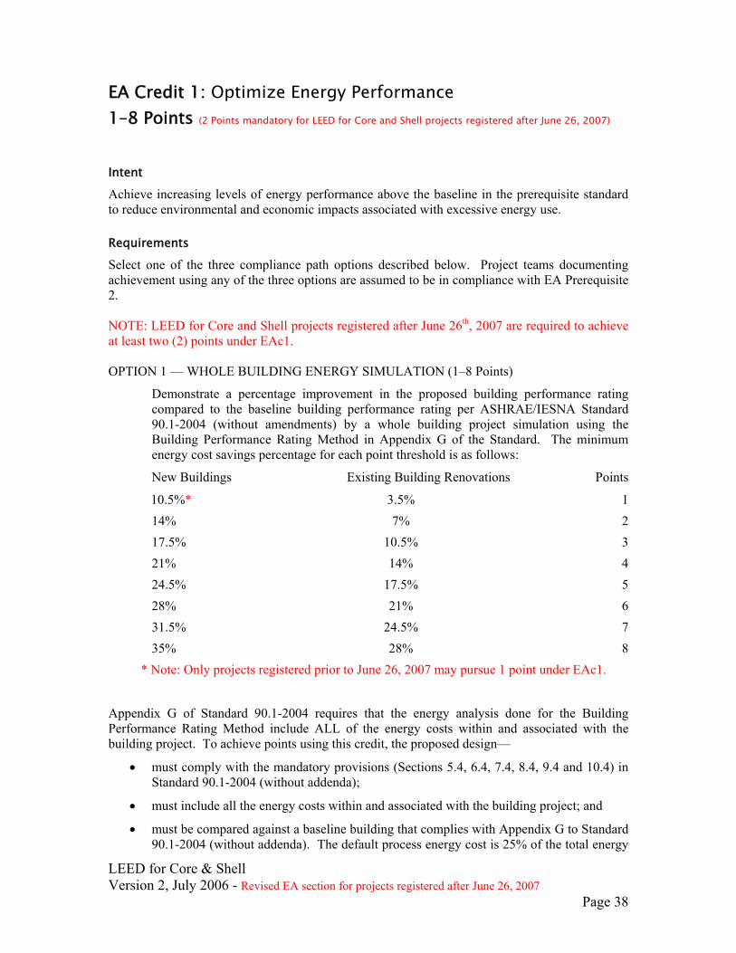
EA Credit 1: Optimize Energy Performance 1–8 Points (2 Points mandatory for LEED for Core and Shell projects registered after June 26, 2007)
Intent
Achieve increasing levels of energy performance above the baseline in the prerequisite standard to reduce environmental and economic impacts associated with excessive energy use.
Requirements
Select one of the three compliance path options described below. Project teams documenting achievement using any of the three options are assumed to be in compliance with EA Prerequisite 2. NOTE: LEED for Core and Shell projects registered after June 26th, 2007 are required to achieve at least two (2) points under EAc1. OPTION 1 — WHOLE BUILDING ENERGY SIMULATION (1–8 Points)
Demonstrate a percentage improvement in the proposed building performance rating compared to the baseline building performance rating per ASHRAE/IESNA Standard 90.1-2004 (without amendments) by a whole building project simulation using the Building Performance Rating Method in Appendix G of the Standard. The minimum energy cost savings percentage for each point threshold is as follows:
New Buildings Existing Building Renovations Points
10.5%* 3.5% 1 14% 7% 2 17.5% 10.5% 3 21% 14% 4 24.5% 17.5% 5 28% 21% 6 31.5% 24.5% 7 35% 28% 8
* Note: Only projects registered prior to June 26, 2007 may pursue 1 point under EAc1.
Appendix G of Standard 90.1-2004 requires that the energy analysis done for the Building Performance Rating Method include ALL of the energy costs within and associated with the building project. To achieve points using this credit, the proposed design—
• must comply with the mandatory provisions (Sections 5.4, 6.4, 7.4, 8.4, 9.4 and 10.4) in Standard 90.1-2004 (without addenda);
• must include all the energy costs within and associated with the building project; and
• must be compared against a baseline building that complies with Appendix G to Standard 90.1-2004 (without addenda). The default process energy cost is 25% of the total energy

LEED for Core & Shell Version 2, July 2006 - Revised EA section for projects registered after June 26, 2007
Page 39
cost for the baseline building. For buildings where the process energy cost is less than 25% of the baseline building energy cost, the LEED submittal must include supporting documentation substantiating that process energy inputs are appropriate.
For the purpose of this analysis, process energy is considered to include, but is not limited to, office and general miscellaneous equipment, computers, elevators and escalators, kitchen cooking and refrigeration, laundry washing and drying, lighting exempt from the lighting power allowance (e.g. lighting integral to medical equipment) and other (e.g. waterfall pumps). Regulated (non-process) energy includes lighting (such as for the interior, parking garage, surface parking, façade, or building grounds, except as noted above), HVAC (such as for space heating, space cooling, fans, pumps, toilet exhaust, parking garage ventilation, kitchen hood exhaust, etc.), and service water heating for domestic or space heating purposes. For EA Credit 1, process loads shall be identical for both the baseline building performance rating and for the proposed building performance rating. However, project teams may follow the Exceptional Calculation Method (ASHRAE 90.1-2004 G2.5) to document measures that reduce process loads. Documentation of process load energy savings shall include a list of the assumptions made for both the base and proposed design, and theoretical or empirical information supporting these assumptions. OR ** OPTION 2 — PRESCRIPTIVE COMPLIANCE PATH (3 Points possible) Comply with the ASHRAE Advanced Energy Design Guide for Small Office Buildings recommendations. Project teams must fully comply with all applicable criteria as established in the ASHRAE Advanced Energy Design Guide for Small Office Buildings for the climate zone in which the building is located. It should be noted that this compliance path may only be used for office buildings up to 20,000 ft2. (Note: the envelope, lighting and HVAC & SWH requirements vary by climate. For each climate there is a table that lists recommended levels for each “system”.)
**LEED for Core and Shell projects registered after June 26th, 2007 are required to achieve at least two (2) points under EAc1
Envelope Performance: (1 point possible)
Install envelope systems which comply with all the envelope recommendations in the ASHRAE Advanced Energy Design Guide for Small Office Buildings table for the climate zone in which the building is located.
Lighting Systems: (1 additional point possible)
Install lighting systems which comply with all the lighting recommendations in the ASHRAE Advanced Energy Design Guide for Small Office Buildings table for the climate zone in which the building is located. All such systems shall be included in systems commissioned under EA P1, Fundamental Building Systems Commissioning.

LEED for Core & Shell Version 2, July 2006 - Revised EA section for projects registered after June 26, 2007
Page 40
HVAC and Service Water Heater Systems: (1 additional point possible)
Install HVAC and Service Water Heating (SWH) systems which comply with all the HVAC & SWH recommendations in the ASHRAE Advanced Energy Design Guide for Small Office Buildings table for the climate zone in which the building is located. All such systems shall be included in systems commissioned under EA P1, Fundamental Building Systems Commissioning. OR *** OPTION 3 — PRESCRIPTIVE COMPLIANCE PATH (1 Point) Comply with the Basic Criteria and Prescriptive Measures of the NBI Advanced Buildings Benchmark™ Version 1.1 with the exception of the following sections: 1.1 Design Certification, 1.2 Construction Certification, 1.3 Operations Certification, 1.4 Energy Code Compliance, 1.7 Monitoring and Trend-logging, 1.11 Indoor Air Quality, 1.13 Refrigeration Equipment Efficiency Requirements, 1.14 Networked Computer Monitor Control, and 2.3 Cool Roofs and EcoRoofs (Zones 1 through 5). The following restrictions apply:
• Project teams must fully comply with all applicable criteria as established in Advanced Buildings Benchmark for the climate zone in which the building is located.
• Project teams must show compliance with all applicable criteria for all systems that are part of the core and shell work.
*** ADVANCED BUILDINGS™ CORE PERFORMANCE™ Note: Option 3 is currently under revision to provide a prescriptive path for projects registered after June 26, 2007 to meet the new 2 point Optimize Energy Performance mandate. Option 3 will be updated to provide guidance for projects when this new path is available. Please check the CIR page on the USGBC Web site for updates.
Potential Technologies & Strategies
Design the building envelope and systems to maximize energy performance. Use a computer simulation model to assess the energy performance and identify the most cost-effective energy efficiency measures. Quantify energy performance as compared to a baseline building. If a local code has demonstrated quantitative and textual equivalence following, at a minimum, the U.S. Department of Energy standard process for commercial energy code determination, then the results of that analysis may be used to correlate local code performance with ASHRAE 90.1-2004. Details on the DOE process for commercial energy code determination can be found at www.energycodes.gov/implement/determinations_com.stm.
LEED for Core & Shell Version 2, July 2006 - Revised EA section for projects registered after June 26, 2007
Page 41
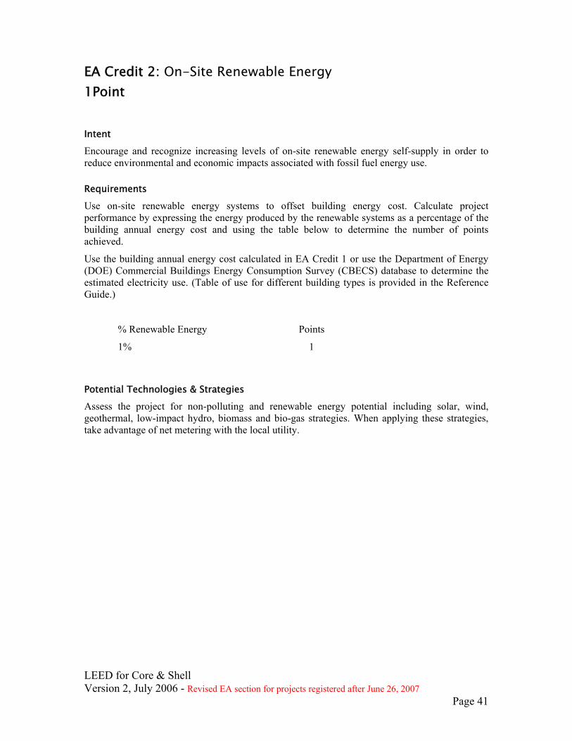
EA Credit 2: On-Site Renewable Energy 1Point Intent
Encourage and recognize increasing levels of on-site renewable energy self-supply in order to reduce environmental and economic impacts associated with fossil fuel energy use.
Requirements
Use on-site renewable energy systems to offset building energy cost. Calculate project performance by expressing the energy produced by the renewable systems as a percentage of the building annual energy cost and using the table below to determine the number of points achieved.
Use the building annual energy cost calculated in EA Credit 1 or use the Department of Energy (DOE) Commercial Buildings Energy Consumption Survey (CBECS) database to determine the estimated electricity use. (Table of use for different building types is provided in the Reference Guide.)
% Renewable Energy Points
1% 1
Potential Technologies & Strategies
Assess the project for non-polluting and renewable energy potential including solar, wind, geothermal, low-impact hydro, biomass and bio-gas strategies. When applying these strategies, take advantage of net metering with the local utility.
LEED for Core & Shell Version 2, July 2006 - Revised EA section for projects registered after June 26, 2007
Page 42
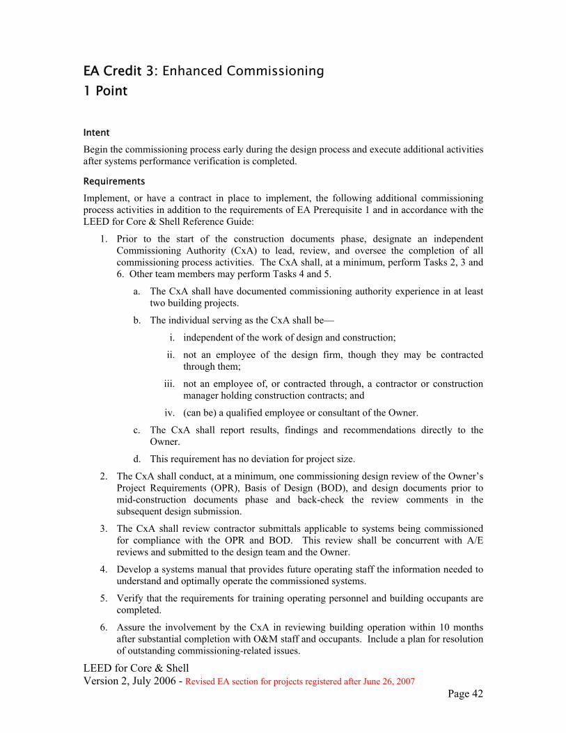
EA Credit 3: Enhanced Commissioning 1 Point Intent
Begin the commissioning process early during the design process and execute additional activities after systems performance verification is completed.
Requirements
Implement, or have a contract in place to implement, the following additional commissioning process activities in addition to the requirements of EA Prerequisite 1 and in accordance with the LEED for Core & Shell Reference Guide:
1. Prior to the start of the construction documents phase, designate an independent Commissioning Authority (CxA) to lead, review, and oversee the completion of all commissioning process activities. The CxA shall, at a minimum, perform Tasks 2, 3 and 6. Other team members may perform Tasks 4 and 5.
a. The CxA shall have documented commissioning authority experience in at least two building projects.
b. The individual serving as the CxA shall be—
i. independent of the work of design and construction;
ii. not an employee of the design firm, though they may be contracted through them;
iii. not an employee of, or contracted through, a contractor or construction manager holding construction contracts; and
iv. (can be) a qualified employee or consultant of the Owner.
c. The CxA shall report results, findings and recommendations directly to the Owner.
d. This requirement has no deviation for project size.
2. The CxA shall conduct, at a minimum, one commissioning design review of the Owner’s Project Requirements (OPR), Basis of Design (BOD), and design documents prior to mid-construction documents phase and back-check the review comments in the subsequent design submission.
3. The CxA shall review contractor submittals applicable to systems being commissioned for compliance with the OPR and BOD. This review shall be concurrent with A/E reviews and submitted to the design team and the Owner.
4. Develop a systems manual that provides future operating staff the information needed to understand and optimally operate the commissioned systems.
5. Verify that the requirements for training operating personnel and building occupants are completed.
6. Assure the involvement by the CxA in reviewing building operation within 10 months after substantial completion with O&M staff and occupants. Include a plan for resolution of outstanding commissioning-related issues.

LEED for Core & Shell Version 2, July 2006 - Revised EA section for projects registered after June 26, 2007
Page 43
Potential Technologies & Strategies
Although it is preferable that the CxA be contracted by the Owner, for the enhanced commissioning credit, the CxA may also be contracted through the design firms or construction management firms not holding construction contracts. The LEED for Core & Shell Reference Guide provides detailed guidance on the rigor expected for following process activities:
• Commissioning design review • Commissioning submittal review • Systems manual

LEED for Core & Shell Version 2, July 2006 - Revised EA section for projects registered after June 26, 2007
Page 44
EA Credit 4: Enhanced Refrigerant Management 1 Point Intent
Reduce ozone depletion and support early compliance with the Montreal Protocol while minimizing direct contributions to global warming.
Requirements
OPTION 1
Do not use refrigerants.
OR
OPTION 2
Select refrigerants and HVAC&R that minimize or eliminate the emission of compounds that contribute to ozone depletion and global warming. The base building HVAC&R equipment shall comply with the following formula, which sets a maximum threshold for the combined contributions to ozone depletion and global warming potential:
LCGWP + LCODP x 105 ≤ 100
Where: LCODP = [ODPr x (Lr x Life +Mr) x Rc]/Life LCGWP = [GWPr x (Lr x Life +Mr) x Rc]/Life LCODP: Lifecycle Ozone Depletion Potential (lbCFC11/Ton-Year) LCGWP: Lifecycle Direct Global Warming Potential (lbCO2/Ton-Year) GWPr: Global Warming Potential of Refrigerant (0 to 12,000 lbCO2/lbr) ODPr: Ozone Depletion Potential of Refrigerant (0 to 0.2 lbCFC11/lbr) Lr: Refrigerant Leakage Rate (0.5% to 2.0%; default of 2% unless otherwise demonstrated) Mr: End-of-life Refrigerant Loss (2% to 10%; default of 10% unless otherwise demonstrated) Rc: Refrigerant Charge (0.5 to 5.0 lbs of refrigerant per ton of cooling capacity) Life: Equipment Life (10 years; default based on equipment type, unless otherwise demonstrated)
For multiple types of equipment, a weighted average of all base building level HVAC&R equipment shall be applied using the following formula:
[ ∑ (LCGWP + LCODP x 105) x Qunit ] / Qtotal ≤ 100 Where:
Qunit = Cooling capacity of an individual HVAC or refrigeration unit (Tons) Qtotal = Total cooling capacity of all HVAC or refrigeration
Small HVAC units (defined as containing less than 0.5 lbs of refrigerant), and other equipment such as standard refrigerators, small water coolers, and any other cooling equipment that contains less than 0.5 lbs of refrigerant, are not considered part of the “base building” system and are not subject to the requirements of this credit. AND

LEED for Core & Shell Version 2, July 2006 - Revised EA section for projects registered after June 26, 2007
Page 45
Do not install fire suppression systems that contain ozone-depleting substances (CFCs, HCFCs or Halons).
Potential Technologies & Strategies
Design and operate the facility without mechanical cooling and refrigeration equipment. Where mechanical cooling is used, utilize base building HVAC and refrigeration systems for the refrigeration cycle that minimize direct impact on ozone depletion and global warming. Select HVAC&R equipment with reduced refrigerant charge and increased equipment life. Maintain equipment to prevent leakage of refrigerant to the atmosphere. Utilize fire suppression systems that do not contain HCFCs or Halons.

LEED for Core & Shell Version 2, July 2006 - Revised EA section for projects registered after June 26, 2007
Page 46
EA Credit 5.1: Measurement & Verification- Base Building 1 Point
Intent
Provide for the ongoing accountability of building energy consumption over time.
Requirements
• Provide the necessary infrastructure within the base building design to facilitate metering building electricity and tenant electrical end-uses as appropriate.
• Develop a building M&V Plan consistent with Option D: Calibrated Simulation (Savings Estimation Method that documents for future tenants the means to measure and minimize energy consumption.. The documentation is to include 1) a description of the infrastructure design, 2) existing meter locations, 3) existing meter specifications, 4) 1-line electrical schematics identifying end-use circuits, 5) guidelines for carrying out tenant sub-metering.
Potential Technologies & Strategies
Develop an M&V Plan to evaluate building and/or energy system performance. Characterize the building and/or energy systems through energy simulation or engineering analysis. Install the necessary metering equipment to measure energy use. Track performance by comparing predicted performance to actual performance, broken down by component or system as appropriate. Evaluate energy efficiency by comparing actual performance to baseline performance. While the IPMVP describes specific actions for verifying savings associated with energy conservation measures (ECMs) and strategies, this LEED credit expands upon typical IPMVP M&V objectives. M&V activities should not necessarily be confined to energy systems where ECMs or energy conservation strategies have been implemented. The IPMVP provides guidance on M&V strategies and their appropriate applications for various situations. These strategies should be used in conjunction with monitoring and trend logging of significant energy systems to provide for the ongoing accountability of building energy performance.

LEED for Core & Shell Version 2, July 2006 - Revised EA section for projects registered after June 26, 2007
Page 47
EA Credit 5.2 Measurement and Verification – Tenant Sub-metering 1 Point
Intent Provide for ongoing accountability of building electricity consumption performance over time.
Requirements
• Include a centrally monitored electronic metering network in the base building design that is capable of being expanded to accommodate the future tenant sub-metering as required by LEED for Commercial Interiors Rating System Credit EA3.
• Develop a tenant M&V Plan that documents and advises future tenants of this
opportunity and the means of their achievement.
Potential Technologies & Strategies
Install the necessary metering and sub-metering equipment to measure energy use. Develop and implement a Measurement & Verification Plan able to be utilized and expanded by the tenant, which compares predicted savings to actual energy performance.

LEED for Core & Shell Version 2, July 2006 - Revised EA section for projects registered after June 26, 2007
Page 48
EA Credit 6: Green Power 1 Point Intent
Encourage the development and use of grid-source, renewable energy technologies on a net zero pollution basis.
Requirements
Provide at least 35% of the core & shell building’s electricity from renewable sources by engaging in at least a two-year renewable energy contract. The core and shell building’s electricity is defined as the electricity usage of the core and shell square footage as defined by BOMA Standards, but not less than 15% of the building total gross square footage. Renewable sources are as defined by the Center for Resource Solutions (CRS) Green-e products certification requirements.
DETERMINE THE BASELINE ELECTRICITY USE
Use the annual electricity consumption from the results of EA Credit 1.
OR
Use the Department of Energy (DOE) Commercial Buildings Energy Consumption Survey (CBECS) database to determine the estimated electricity use.
Potential Technologies & Strategies
Determine the energy needs of the building and investigate opportunities to engage in a green power contract. Green power is derived from solar, wind, geothermal, biomass or low-impact hydro sources. Visit www.green-e.org for details about the Green-e program. The power product purchased to comply with credit requirements need not be Green-e certified. Other sources of green power are eligible if they satisfy the Green-e program’s technical requirements. Renewable energy certificates (RECs), tradable renewable certificates (TRCs), green tags and other forms of green power that comply with Green-e’s technical requirements can be used to document compliance with EA Credit 6 requirements.
LEED for Core & Shell Version 2, July 2006 - Revised EA section for projects registered after June 26, 2007
Page 49
Materials & Resources MR Prerequisite 1: Storage & Collection of Recyclables Required Intent
Facilitate the reduction of waste generated by building occupants that is hauled to and disposed of in landfills.
Requirements
Provide an easily accessible area that serves the entire building and is dedicated to the collection and storage of non-hazardous materials for recycling, including (at a minimum) paper, corrugated cardboard, glass, plastics and metals.
Potential Technologies & Strategies
Coordinate the size and functionality of the recycling areas with the anticipated collection services for glass, plastic, office paper, newspaper, cardboard and organic wastes to maximize the effectiveness of the dedicated areas. Consider employing cardboard balers, aluminum can crushers, recycling chutes and collection bins at individual workstations to further enhance the recycling program.

LEED for Core & Shell Version 2, July 2006 - Revised EA section for projects registered after June 26, 2007
Page 50
MR Credit 1.1: Building Reuse: Maintain 25%, of Existing Walls, Floors & Roof 1 Point Intent
Extend the life cycle of existing building stock, conserve resources, retain cultural resources, reduce waste and reduce environmental impacts of new buildings as they relate to materials manufacturing and transport.
Requirements
Maintain at least 25% (based on surface area) of existing building structure (including structural floor and roof decking) and envelope (exterior skin and framing, excluding window assemblies and non-structural roofing material). Hazardous materials that are remediated as a part of the project scope shall be excluded from the calculation of the percentage maintained. If the project includes an addition to an existing building, this credit is not applicable if the square footage of the addition is more than 6 times the square footage of the pre-existing building.
Potential Technologies & Strategies
Consider reuse of existing, previously occupied buildings, including structure, envelope and elements. Remove elements that pose contamination risk to building occupants and upgrade components that would improve energy and water efficiency such as windows, mechanical systems and plumbing fixtures.

LEED for Core & Shell Version 2, July 2006 - Revised EA section for projects registered after June 26, 2007
Page 51
MR Credit 1.2: Building Reuse: Maintain 50%, of Existing Walls, Floors & Roof 1 Point Intent
Extend the life cycle of existing building stock, conserve resources, retain cultural resources, reduce waste and reduce environmental impacts of new buildings as they relate to materials manufacturing and transport.
Requirements Maintain at least 50% (based on surface area) of existing building structure (including structural floor and roof decking) and envelope (exterior skin and framing, excluding window assemblies and non-structural roofing material). Hazardous materials that are remediated as a part of the project scope shall be excluded from the calculation of the percentage maintained. If the project includes an addition to an existing building, this credit is not applicable if the square footage of the addition is more than 6 times the square footage of the pre-existing building.
Potential Technologies & Strategies
Consider reuse of existing, previously occupied buildings, including structure, envelope and elements. Remove elements that pose contamination risk to building occupants and upgrade components that would improve energy and water efficiency such as windows, mechanical systems and plumbing fixtures.

LEED for Core & Shell Version 2, July 2006 - Revised EA section for projects registered after June 26, 2007
Page 52
MR Credit 1.3: Building Reuse: Maintain 75%, of Existing Walls, Floors & Roof 1 Point Intent
Extend the life cycle of existing building stock, conserve resources, retain cultural resources, reduce waste and reduce environmental impacts of new buildings as they relate to materials manufacturing and transport.
Requirements
Maintain at least 75% (based on surface area) of existing building structure (including structural floor and roof decking) and envelope (exterior skin and framing, excluding window assemblies and non-structural roofing material). Hazardous materials that are remediated as a part of the project scope shall be excluded from the calculation of the percentage maintained. If the project includes an addition to an existing building, this credit is not applicable if the square footage of the addition is more than 6 times the square footage of the pre-existing building.
Potential Technologies & Strategies
Consider reuse of existing, previously occupied buildings, including structure, envelope and elements. Remove elements that pose contamination risk to building occupants and upgrade components that would improve energy and water efficiency such as windows, mechanical systems and plumbing fixtures.
LEED for Core & Shell Version 2, July 2006 - Revised EA section for projects registered after June 26, 2007
Page 53
MR Credit 2.1: Construction Waste Management: Divert 50% From Disposal 1 Point Intent
Divert construction and demolition debris from disposal in landfills and incinerators. Redirect recyclable recovered resources back to the manufacturing process. Redirect reusable materials to appropriate sites.
Requirements
Recycle and/or salvage at least 50% of non-hazardous construction and demolition debris. Develop and implement a construction waste management plan that, at a minimum, identifies the materials to be diverted from disposal and whether the materials will be sorted on-site or co-mingled. Excavated soil and land-clearing debris do not contribute to this credit. Calculations can be done by weight or volume, but must be consistent throughout.
Potential Technologies & Strategies
Establish goals for diversion from disposal in landfills and incinerators and adopt a construction waste management plan to achieve these goals. Consider recycling cardboard, metal, brick, acoustical tile, concrete, plastic, clean wood, glass, gypsum wallboard, carpet and insulation. Designate a specific area(s) on the construction site for segregated or commingled collection of recyclable materials, and track recycling efforts throughout the construction process. Identify construction haulers and recyclers to handle the designated materials. Note that diversion may include donation of materials to charitable organizations and salvage of materials on-site.

LEED for Core & Shell Version 2, July 2006 - Revised EA section for projects registered after June 26, 2007
Page 54
MR Credit 2.2: Construction Waste Management: Divert 75% From Disposal 1 Point in addition to MR Credit 2.1 Intent
Divert construction and demolition debris from disposal in landfills and incinerators. Redirect recyclable recovered resources back to the manufacturing process. Redirect reusable materials to appropriate sites.
Requirements
Recycle and/or salvage an additional 25% beyond MR Credit 2.1 (75% total) of non-hazardous construction and demolition debris. Excavated soil and land-clearing debris do not contribute to this credit. Calculations can be done by weight or volume, but must be consistent throughout.
Potential Technologies & Strategies
Establish goals for diversion from disposal in landfills and incinerators and adopt a construction waste management plan to achieve these goals. Consider recycling cardboard, metal, brick, acoustical tile, concrete, plastic, clean wood, glass, gypsum wallboard, carpet and insulation. Designate a specific area(s) on the construction site for segregated or commingled collection of recyclable materials, and track recycling efforts throughout the construction process. Identify construction haulers and recyclers to handle the designated materials. Note that diversion may include donation of materials to charitable organizations and salvage of materials on-site.

LEED for Core & Shell Version 2, July 2006 - Revised EA section for projects registered after June 26, 2007
Page 55
MR Credit 3: Materials Reuse: 1% 1 Point Intent
Reuse building materials and products in order to reduce demand for virgin materials and to reduce waste, thereby reducing impacts associated with the extraction and processing of virgin resources.
Requirements
Use salvaged, refurbished or reused materials such that the sum of these materials constitutes at least 1%, based on cost, of the total value of materials on the project.
Mechanical, electrical and plumbing components and specialty items such as elevators and equipment shall not be included in this calculation. Only include materials permanently installed in the project. Furniture may be included, providing it is included consistently in MR Credits 3–7.
Potential Technologies & Strategies
Identify opportunities to incorporate salvaged materials into building design and research potential material suppliers. Consider salvaged materials such as beams and posts, flooring, paneling, doors and frames, cabinetry and furniture, brick and decorative items.

LEED for Core & Shell Version 2, July 2006 - Revised EA section for projects registered after June 26, 2007
Page 56
MR Credit 4.1: Recycled Content: 10% (post-consumer + 1/2 pre-consumer) 1 Point Intent
Increase demand for building products that incorporate recycled content materials, thereby reducing impacts resulting from extraction and processing of virgin materials.
Requirements
Use materials with recycled content such that the sum of post-consumer recycled content plus one-half of the pre-consumer content constitutes at least 10% (based on cost) of the total value of the materials in the project.
The recycled content value of a material assembly shall be determined by weight. The recycled fraction of the assembly is then multiplied by the cost of assembly to determine the recycled content value.
Mechanical, electrical and plumbing components and specialty items such as elevators shall not be included in this calculation. Only include materials permanently installed in the project. Furniture may be included, providing it is included consistently in MR Credits 3–7. Recycled content shall be defined in accordance with the International Organization of Standards document, ISO 14021—Environmental labels and declarations—Self-declared environmental claims (Type II environmental labeling).
Post-consumer material is defined as waste material generated by households or by commercial, industrial and institutional facilities in their role as end-users of the product, which can no longer be used for its intended purpose.
Pre-consumer material is defined as material diverted from the waste stream during the manufacturing process. Excluded is reutilization of materials such as rework, regrind or scrap generated in a process and capable of being reclaimed within the same process that generated it.
Potential Technologies & Strategies
Establish a project goal for recycled content materials and identify material suppliers that can achieve this goal. During construction, ensure that the specified recycled content materials are installed. Consider a range of environmental, economic and performance attributes when selecting products and materials.
LEED for Core & Shell Version 2, July 2006 - Revised EA section for projects registered after June 26, 2007
Page 57
MR Credit 4.2: Recycled Content: 20% (post-consumer + 1/2 pre-consumer) 1 Point in addition to MR Credit 4.1 Intent
Increase demand for building products that incorporate recycled content materials, thereby reducing the impacts resulting from extraction and processing of virgin materials.
Requirements
Use materials with recycled content such that the sum of post-consumer recycled content plus one-half of the pre-consumer content constitutes an additional 10% beyond MR Credit 4.1 (total of 20%, based on cost) of the total value of the materials in the project.
The recycled content value of a material assembly shall be determined by weight. The recycled fraction of the assembly is then multiplied by the cost of assembly to determine the recycled content value.
Mechanical, electrical and plumbing components and specialty items such as elevators shall not be included in this calculation. Only include materials permanently installed in the project. Furniture may be included, providing it is included consistently in MR Credits 3–7. Recycled content shall be defined in accordance with the International Organization of Standards document, ISO 14021—Environmental labels and declarations—Self-declared environmental claims (Type II environmental labeling).
Post-consumer material is defined as waste material generated by households or by commercial, industrial and institutional facilities in their role as end-users of the product, which can no longer be used for its intended purpose.
Pre-consumer material is defined as material diverted from the waste stream during the manufacturing process. Excluded is reutilization of materials such as rework, regrind or scrap generated in a process and capable of being reclaimed within the same process that generated it.
Potential Technologies & Strategies
Establish a project goal for recycled content materials and identify material suppliers that can achieve this goal. During construction, ensure that the specified recycled content materials are installed. Consider a range of environmental, economic and performance attributes when selecting products and materials.

LEED for Core & Shell Version 2, July 2006 - Revised EA section for projects registered after June 26, 2007
Page 58
MR Credit 5.1: Regional Materials: 10% Extracted, Processed & Manufactured Regionally 1 Point Intent
Increase demand for building materials and products that are extracted and manufactured within the region, thereby supporting the use of indigenous resources and reducing the environmental impacts resulting from transportation.
Requirements
Use building materials or products that have been extracted, harvested or recovered, as well as manufactured, within 500 miles of the project site for a minimum of 10% (based on cost) of the total materials value. If only a fraction of a product or material is extracted/harvested/recovered and manufactured locally, then only that percentage (by weight) shall contribute to the regional value. Mechanical, electrical and plumbing components and specialty items such as elevators and equipment shall not be included in this calculation. Only include materials permanently installed in the project. Furniture may be included, providing it is included consistently in MR Credits 3–7.
Potential Technologies & Strategies
Establish a project goal for locally sourced materials, and identify materials and material suppliers that can achieve this goal. During construction, ensure that the specified local materials are installed and quantify the total percentage of local materials installed. Consider a range of environmental, economic and performance attributes when selecting products and materials.
LEED for Core & Shell Version 2, July 2006 - Revised EA section for projects registered after June 26, 2007
Page 59
MR Credit 5.2: Regional Materials: 20% Extracted, Processed & Manufactured Regionally 1 Point in addition to MR Credit 5.1 Intent
Increase demand for building materials and products that are extracted and manufactured within the region, thereby supporting the use of indigenous resources and reducing the environmental impacts resulting from transportation.
Requirements
Use building materials or products that have been extracted, harvested or recovered, as well as manufactured, within 500 miles of the project site for an additional 10% beyond MR Credit 5.1 (total of 20%, based on cost) of the total materials value. If only a fraction of the material is extracted/harvested/recovered and manufactured locally, then only that percentage (by weight) shall contribute to the regional value.
Potential Technologies & Strategies
Establish a project goal for locally sourced materials and identify materials and material suppliers that can achieve this goal. During construction, ensure that the specified local materials are installed. Consider a range of environmental, economic and performance attributes when selecting products and materials.
LEED for Core & Shell Version 2, July 2006 - Revised EA section for projects registered after June 26, 2007
Page 60
MR Credit 6: Certified Wood 1 Point Intent Encourage environmentally responsible forest management.
Requirements
Use a minimum of 50% of wood-based materials and products, which are certified in accordance with the Forest Stewardship Council’s (FSC) Principles and Criteria, for wood building components. These components include, but are not limited to, structural framing and general dimensional framing, flooring, sub-flooring, wood doors, and finishes.
Include materials permanently installed in the project. Furniture may be included, providing it is included consistently in MR Credits 3–7. At the projects discretion, calculation may include temporary wood materials purchased for the project. If any such materials are included, all such materials must be included in the calculation.
Potential Technologies & Strategies
Establish a project goal for FSC-certified wood products and identify suppliers that can achieve this goal. During construction, ensure that the FSC-certified wood products are installed and quantify the total percentage of FSC-certified wood products installed.

LEED for Core & Shell Version 2, July 2006 - Revised EA section for projects registered after June 26, 2007
Page 61
Indoor Environmental Quality
EQ Prerequisite 1: Minimum IAQ Performance Required Intent
Establish minimum indoor air quality (IAQ) performance to enhance indoor air quality in buildings, thus contributing to the comfort and well-being of the occupants.
Requirements
Meet the minimum requirements of Sections 4 through 7 of ASHRAE 62.1-2004, Ventilation for Acceptable Indoor Air Quality. Mechanical ventilation systems shall be designed using the Ventilation Rate Procedure or the applicable local code, whichever is more stringent.
Naturally ventilated buildings shall comply with ASHRAE 62.1-2004, paragraph 5.1.
Mechanical ventilation systems installed during core and shell construction shall be capable of meeting projected ventilation levels based on anticipated future tenant requirements.
Potential Technologies & Strategies
Design ventilation systems to meet or exceed the minimum outdoor air ventilation rates as described in the ASHRAE standard. Balance the impacts of ventilation rates on energy use and indoor air quality to optimize for energy efficiency and occupant health. Use the ASHRAE 62 Users Manual for detailed guidance on meeting the referenced requirements.

LEED for Core & Shell Version 2, July 2006 - Revised EA section for projects registered after June 26, 2007
Page 62
EQ Prerequisite 2: Environmental Tobacco Smoke (ETS) Control Required Intent
Minimize exposure of building occupants, indoor surfaces, and ventilation air distribution systems to Environmental Tobacco Smoke (ETS).
Requirements
OPTION 1
• Prohibit smoking in the building.
• Locate any exterior designated smoking areas at least 25 feet away from entries, outdoor air intakes and operable windows.
OR
OPTION 2
• Prohibit smoking in the public areas of the building except in designated smoking areas. Public areas include all common areas that are part of the core and shell that are not tenant spaces. Prohibit smoking in the building except in designated smoking areas
• Locate any exterior designated smoking areas at least 25 feet away from entries, outdoor air intakes and operable windows.
• Locate designated smoking areas to effectively contain, capture and remove ETS from the building. At a minimum, the smoking room must be directly exhausted to the outdoors with no re-circulation of ETS-containing air to the non-smoking area of the building, and enclosed with impermeable deck-to-deck partitions. With the doors to the smoking room closed, operate exhaust sufficient to create a negative pressure with respect to the adjacent spaces of at least an average of 5 Pa (0.02 inches of water gauge) and with a minimum of 1 Pa (0.004 inches of water gauge).
• Performance of the smoking room differential air pressures shall be verified by conducting 15 minutes of measurement, with a minimum of one measurement every 10 seconds, of the differential pressure in the smoking room with respect to each adjacent area and in each adjacent vertical chase with the doors to the smoking room closed. The testing will be conducted with each space configured for worst case conditions of transport of air from the smoking rooms to adjacent spaces with the smoking rooms’ doors closed to the adjacent spaces.
OR
OPTION 3 (For residential buildings only)
• Prohibit smoking in all common areas of the building.
• Locate any exterior designated smoking areas at least 25 feet away from entries, outdoor air intakes and operable windows opening to common areas.

LEED for Core & Shell Version 2, July 2006 - Revised EA section for projects registered after June 26, 2007
Page 63
• Minimize uncontrolled pathways for ETS transfer between individual residential units by sealing penetrations in walls, ceilings and floors in the residential units, and by sealing vertical chases adjacent to the units.
• All doors in the residential units leading to common hallways shall be weather-stripped to minimize air leakage into the hallway.
• If the common hallways are pressurized with respect to the residential units then doors in the residential units leading to the common hallways need not be weather-stripped provided that the positive differential pressure is demonstrated as in Option 2 above, considering the residential unit as the smoking room. Acceptable sealing of residential units shall be demonstrated by a blower door test conducted in accordance with ANSI/ASTM-E779-03, Standard Test Method for Determining Air Leakage Rate By Fan Pressurization, AND use the progressive sampling methodology defined in Chapter 4 (Compliance Through Quality Construction) of the Residential Manual for Compliance with California’s 2001 Energy Efficiency Standards (www.energy.ca.gov/title24/residential_manual). Residential units must demonstrate less than 1.25 square inches leakage area per 100 square feet of enclosure area (i.e. sum of all wall, ceiling and floor areas).
Potential Technologies & Strategies
Prohibit smoking in commercial buildings or effectively control the ventilation air in smoking rooms. For residential buildings, prohibit smoking in common areas, design building envelope and systems to minimize ETS transfer among dwelling units.
LEED for Core & Shell Version 2, July 2006 - Revised EA section for projects registered after June 26, 2007
Page 64
EQ Credit 1: Outdoor Air Delivery Monitoring 1 Point Intent
Provide capacity for ventilation system monitoring to help sustain occupant comfort and well-being.
Requirements
Install permanent monitoring systems that provide feedback on ventilation system performance to ensure that ventilation systems maintain design minimum ventilation requirements. Configure all monitoring equipment to generate an alarm when the conditions vary by 10% or more from setpoint, via either a building automation system alarm to the building operator or via a visual or audible alert to the building occupants.
FOR MECHANICALLY VENTILATED SPACES
• For each mechanical ventilation system, provide a direct outdoor airflow measurement device capable of measuring the minimum outdoor airflow rate with an accuracy of plus or minus 15% of the design minimum outdoor air rate, as defined by ASHRAE 62.1-2004.
FOR NATURALLY VENTILATED SPACES
Monitor CO2 concentrations within all naturally ventilated spaces. CO2 monitoring shall be located within the room between 3 feet and 6 feet above the floor. One CO2 sensor may be used to represent multiple spaces if the natural ventilation design uses passive stack(s) or other means to induce airflow through those spaces equally and simultaneously without intervention by building occupants.
Potential Technologies & Strategies
Install carbon dioxide and airflow measurement equipment and feed the information to the HVAC system and/or Building Automation System (BAS) to trigger corrective action, if applicable. If such automatic controls are not feasible with the building systems, use the measurement equipment to trigger alarms that inform building operators or occupants of a possible deficiency in outdoor air delivery.
Installation of CO2 sensors in tenant spaces is not required during core and shell construction and tenants are not required to install CO2 monitors, however they should be made aware of the capability of the core and shell system to monitor CO2. The core and shell systems must be designed with the capacity for CO2 monitoring. This entails a building automation system that can be expanded to include future tenant CO2 points.

LEED for Core & Shell Version 2, July 2006 - Revised EA section for projects registered after June 26, 2007
Page 65
EQ Credit 2: Increased Ventilation 1 Point Intent
Provide additional outdoor air ventilation to improve indoor air quality for improved occupant comfort, well-being and productivity.
Requirements
FOR MECHANICALLY VENTILATED SPACES
• Increase breathing zone outdoor air ventilation rates to all occupied spaces by at least 30% above the minimum rates required by ASHRAE Standard 62.1-2004 as determined by EQ Prerequisite 1.
FOR NATURALLY VENTILATED SPACES
Design natural ventilation systems for occupied spaces to meet the recommendations set forth in the Carbon Trust “Good Practice Guide 237” [1998]. Determine that natural ventilation is an effective strategy for the project by following the flow diagram process shown in Figure 1.18 of the Chartered Institution of Building Services Engineers (CIBSE) Applications Manual 10: 2005, Natural ventilation in non-domestic buildings.
AND
• Use diagrams and calculations to show that the design of the natural ventilation systems meets the recommendations set forth in the CIBSE Applications Manual 10: 2005, Natural ventilation in non-domestic buildings.
OR
• Use a macroscopic, multi-zone, analytic model to predict that room-by-room airflows will effectively naturally ventilate, defined as providing the minimum ventilation rates required by ASHRAE 62.1-2004 Chapter 6, for at least 90% of occupied spaces.
• The core and shell buildings that are designed to be naturally ventilated must provide the capability for the tenant build-out to meet the requirements of this credit.
Potential Technologies & Strategies
For Mechanically ventilated Spaces: Use heat recovery, where appropriate, to minimize the additional energy consumption associated with higher ventilation rates.
For Naturally ventilated Spaces: Follow the eight design steps described in the Carbon Trust Good Practice Guide 237 – 1) Develop design requirements, 2) Plan airflow paths, 3) Identify building uses and features that might require special attention, 4) Determine ventilation requirements, 5) Estimate external driving pressures, 6) Select types of ventilation devices, 7) Size ventilation devices, 8) Analyze the design. Use public domain software such as NIST’s CONTAM, Multizone Modeling Software, along with LoopDA, Natural Ventilation Sizing Tool, to analytically predict room-by-room airflows.

LEED for Core & Shell Version 2, July 2006 - Revised EA section for projects registered after June 26, 2007
Page 66
EQ Credit 3: Construction IAQ Management Plan: During Construction 1 Point Intent
Reduce indoor air quality problems resulting from the construction/renovation process in order to help sustain the comfort and well-being of construction workers and building occupants.
Requirements
Develop and implement an Indoor Air Quality (IAQ) Management Plan for the construction and pre-occupancy phases of the building as follows:
• During construction meet or exceed the recommended Control Measures of the Sheet Metal and Air Conditioning National Contractors Association (SMACNA) IAQ Guidelines for Occupied Buildings under Construction, 1995, Chapter 3.
• Protect stored on-site or installed absorptive materials from moisture damage. • If permanently installed air handlers are used during construction, filtration media with a
Minimum Efficiency Reporting Value (MERV) of 8 shall be used at each return air grille, as determined by ASHRAE 52.2-1999. Replace all filtration media immediately prior to occupancy.
Potential Technologies & Strategies
Adopt an IAQ management plan to protect the HVAC system during construction, control pollutant sources and interrupt contamination pathways. Sequence the installation of materials to avoid contamination of absorptive materials such as insulation, carpeting, ceiling tile and gypsum wallboard. Coordinate with Indoor Environmental Quality Credit 5 to determine the appropriate specifications and schedules for filtration media.
If possible, avoid using permanently installed air handlers for temporary heating/cooling during construction. Consult the LEED for Core & Shell Reference Guide for more detailed information on how to ensure the well-being of construction workers and building occupants if permanently installed air handlers must be used during construction.

EQ Credit 4.1: Low-Emitting Materials: Adhesives & Sealants 1 Point for Achievement of 2 (4.1, 4.2, 4.3 or 4.4)
2 Points for Achievement of 3 (4.1, 4.2, 4.3 or 4.4)
3 Points for Achievement of 4 (4.1, 4.2, 4.3 or 4.4)
Intent
Reduce the quantity of indoor air contaminants that are odorous, irritating and/or harmful to the comfort and well-being of installers and occupants.
Requirements
All adhesives and sealants used on the interior of the building (defined as inside of the weatherproofing system and applied on-site) shall comply with the requirements of the following reference standards:
• Adhesives, Sealants and Sealant Primers: South Coast Air Quality Management District (SCAQMD) Rule #1168. VOC limits are listed in the table below and correspond to an effective date of July 1, 2005 and rule amendment date of January 7, 2005.
Architectural Applications VOC Limit [g/L less water] Specialty Applications VOC Limit [g/L less
water] Indoor Carpet Adhesives 50 PVC Welding 510 Carpet Pad Adhesives 50 CPVC Welding 490 Wood Flooring Adhesives 100 ABS Welding 325 Rubber Floor Adhesives 60 Plastic Cement Welding 250 Subfloor Adhesives 50 Adhesive Primer for Plastic 550 Ceramic Tile Adhesives 65 Contact Adhesive 80 VCT & Asphalt Adhesives 50 Special Purpose Contact Adhesive 250 Drywall & Panel Adhesives 50 Structural Wood Member Adhesive 140 Cove Base Adhesives 50 Sheet Applied Rubber Lining Operations 850 Multipurpose Construction Adhesives 70 Top & Trim Adhesive 250 Structural Glazing Adhesives 100
Substrate Specific Applications VOC Limit [g/L less water] Sealants VOC Limit [g/L less
water] Metal to Metal 30 Architectural 250 Plastic Foams 50 Nonmembrane Roof 300 Porous Material (except wood) 50 Roadway 250 Wood 30 Single-Ply Roof Membrane 450 Fiberglass 80 Other 420 Sealant Primers VOC Limit [g/L less water] Architectural Non Porous 250 Architectural Porous 775 Other 750
• Aerosol Adhesives: Green Seal Standard for Commercial Adhesives GS-36 requirements in effect on October 19, 2000.
LEED for Core & Shell Version 2, July 2006 - Revised EA section for projects registered after June 26, 2007
Page 67
Aerosol Adhesives: VOC weight [g/L minus water]General purpose mist spray 65% VOCs by weightGeneral purpose web spray 55% VOCs by weightSpecial purpose aerosol adhesives (all types) 70% VOCs by weight
LEED for Core & Shell Version 2, July 2006 - Revised EA section for projects registered after June 26, 2007
Page 68
Potential Technologies & Strategies
Specify low-VOC materials in construction documents. Ensure that VOC limits are clearly stated in each section of the specifications where adhesives and sealants are addressed. Common products to evaluate include: general construction adhesives, flooring adhesives, fire-stopping sealants, caulking, duct sealants, plumbing adhesives, and cove base adhesives.
LEED for Core & Shell Version 2, July 2006 - Revised EA section for projects registered after June 26, 2007
Page 69
EQ Credit 4.2: Low-Emitting Materials: Paints & Coatings 1 Point for Achievement of 2 (4.1, 4.2, 4.3 or 4.4)
2 Points for Achievement of 3 (4.1, 4.2, 4.3 or 4.4)
3 Points for Achievement of 4 (4.1, 4.2, 4.3 or 4.4)
Intent
Reduce the quantity of indoor air contaminants that are odorous, irritating and/or harmful to the comfort and well-being of installers and occupants.
Requirements
Paints and coatings used on the interior of the building (defined as inside of the weatherproofing system and applied on-site) shall comply with the following criteria:
• Architectural paints, coatings and primers applied to interior walls and ceilings: Do not exceed the VOC content limits established in Green Seal Standard GS-11, Paints, First Edition, May 20, 1993.
o Flats: 50 g/L
o Non-Flats: 150 g/L
• Anti-corrosive and anti-rust paints applied to interior ferrous metal substrates: Do not exceed the VOC content limit of 250 g/L established in Green Seal Standard GC-03, Anti-Corrosive Paints, Second Edition, January 7, 1997.
• Clear wood finishes, floor coatings, stains, and shellacs applied to interior elements: Do not exceed the VOC content limits established in South Coast Air Quality Management District (SCAQMD) Rule 1113, Architectural Coatings, rules in effect on January 1, 2004.
o Clear wood finishes: varnish 350 g/L; lacquer 550 g/L
o Floor coatings: 100 g/L
o Sealers: waterproofing sealers 250 g/L; sanding sealers 275 g/L; all other sealers 200 g/L
o Shellacs: Clear 730 g/L; pigmented 550 g/L
o Stains: 250 g/L
Potential Technologies & Strategies
Specify low-VOC paints and coatings in construction documents. Ensure that VOC limits are clearly stated in each section of the specifications where paints and coatings are addressed. Track the VOC content of all interior paints and coatings during construction.
LEED for Core & Shell Version 2, July 2006 - Revised EA section for projects registered after June 26, 2007
Page 70
EQ Credit 4.3: Low-Emitting Materials: Carpet Systems 1 Point for Achievement of 2 (4.1, 4.2, 4.3 or 4.4)
2 Points for Achievement of 3 (4.1, 4.2, 4.3 or 4.4)
3 Points for Achievement of 4 (4.1, 4.2, 4.3 or 4.4)
Intent
Reduce the quantity of indoor air contaminants that are odorous, irritating and/or harmful to the comfort and well-being of installers and occupants.
Requirements
All carpet installed in the building interior shall meet the testing and product requirements of the Carpet and Rug Institute’s Green Label Plus program.
All carpet cushion installed in the building interior shall meet the requirements of the Carpet and Rug Institute Green Label program.
All carpet adhesive shall meet the requirements of EQ Credit 4.1: VOC limit of 50 g/L.
Potential Technologies & Strategies
Clearly specify requirements for product testing and/or certification in the construction documents. Select products that are either certified under the Green Label Plus program or for which testing has been done by qualified independent laboratories in accordance with the appropriate requirements.
The Green Label Plus program for carpets and its associated VOC emission criteria in micrograms per square meter per hour, along with information on testing method and sample collection developed by the Carpet & Rug Institute (CRI) in coordination with California’s Sustainable Building Task Force and the California Department of Health Services (DHS), are described in Section 9, Acceptable Emissions Testing for Carpet, DHS Standard Practice CA/DHS/EHLB/R-174, dated 07/15/04. This document is available at: www.dhs.ca.gov/ps/deodc/ehlb/iaq/VOCS/Section01350_7_15_2004_FINAL_PLUS_ADDENDUM-2004-01.pdf (also published as Section 01350 Section 9 [dated 2004] by the Collaborative for High Performance Schools [www.chps.net]).

LEED for Core & Shell Version 2, July 2006 - Revised EA section for projects registered after June 26, 2007
Page 71
EQ Credit 4.4: Low-Emitting Materials: Composite Wood & Agrifiber Products 1 Point for Achievement of 2 (4.1, 4.2, 4.3 or 4.4)
2 Points for Achievement of 3 (4.1, 4.2, 4.3 or 4.4)
3 Points for Achievement of 4 (4.1, 4.2, 4.3 or 4.4)
Intent
Reduce the quantity of indoor air contaminants that are odorous, irritating and/or harmful to the comfort and well-being of installers and occupants.
Requirements
Composite wood and agrifiber products used on the interior of the building (defined as inside of the weatherproofing system) shall contain no added urea-formaldehyde resins. Laminating adhesives used to fabricate on-site and shop-applied composite wood and agrifiber assemblies shall contain no added urea-formaldehyde resins.
Composite wood and agrifiber products are defined as: particleboard, medium density fiberboard (MDF), plywood, wheatboard, strawboard, panel substrates and door cores. Materials considered fit-out are not considered base building elements and are not included.
Potential Technologies & Strategies
Specify wood and agrifiber products that contain no added urea-formaldehyde resins. Specify laminating adhesives for field and shop applied assemblies that contain no added urea-formaldehyde resins.

LEED for Core & Shell Version 2, July 2006 - Revised EA section for projects registered after June 26, 2007
Page 72
EQ Credit 5: Indoor Chemical & Pollutant Source Control 1 Point Intent
Minimize exposure of building occupants to potentially hazardous particulates and chemical pollutants.
Requirements
Design to minimize and control pollutant entry into buildings and later cross-contamination of regularly occupied areas:
• Employ permanent entryway systems at least six feet long in the primary direction of travel to capture dirt and particulates from entering the building at all entryways that are directly connected to the outdoors. Acceptable entryway systems include permanently installed grates, grilles, or slotted systems that allow for cleaning underneath. Roll-out mats are only acceptable when maintained on a weekly basis by a contracted service organization. Qualifying entryways are those that serve as regular entry points into the core and shell of the building by building users. Projects that do not have entryway systems cannot achieve this credit.
• Where hazardous gases or chemicals may be present or used (including garages, housekeeping/laundry areas and copying/printing rooms), exhaust each space sufficiently to create negative pressure with respect to adjacent spaces with the doors to the room closed. For each of these spaces, provide self-closing doors and deck to deck partitions or a hard lid ceiling. The exhaust rate shall be at least 0.50 cfm/sq.ft., with no air re-circulation. The pressure differential with the surrounding spaces shall be at least 5 Pa (0.02 inches of water gauge) on average and 1 Pa (0.004 inches of water) at a minimum when the doors to the rooms are closed.
• In mechanically ventilated buildings, provide regularly occupied areas of the building with air filtration media prior to occupancy that provides a Minimum Efficiency Reporting Value (MERV) of 13 or better. Filtration should be applied to process both return and outside air that is to be delivered as supply air.
Potential Technologies & Strategies
Design facility cleaning and maintenance areas with isolated exhaust systems for contaminants. Maintain physical isolation from the rest of the regularly occupied areas of the building. Install permanent architectural entryway systems such as grills or grates to prevent occupant-borne contaminants from entering the building. Install high-level filtration systems in air handling units processing both return air and outside supply air. Ensure that air handling units can accommodate required filter sizes and pressure drops.

LEED for Core & Shell Version 2, July 2006 - Revised EA section for projects registered after June 26, 2007
Page 73
EQ Credit 6: Controllability of Systems: Thermal Comfort 1 Point Intent
Provide a high level of thermal comfort system control by individual occupants or by specific groups in multi-occupant spaces (i.e. classrooms or conference areas) to promote the productivity, comfort and well-being of building occupants.
Requirements
Provide individual comfort controls for 50% (minimum) of the building occupants to enable adjustments to suit individual task needs and preferences. Operable windows can be used in lieu of comfort controls for occupants of areas that are 20 feet inside of and 10 feet to either side of the operable part of the window. The areas of operable window must meet the requirements of ASHRAE 62.1-2004 paragraph 5.1 Natural Ventilation.
AND
Provide comfort system controls for all shared multi-occupant spaces to enable adjustments to suit group needs and preferences.
Conditions for thermal comfort are described in ASHRAE Standard 55-2004 to include the primary factors of air temperature, radiant temperature, air speed and humidity. Comfort system control for the purposes of this credit is defined as the provision of control over at least one of these primary factors in the occupant’s local environment.
Core & Shell buildings that do not purchase and/or install the mechanical system or operable windows (or a combination of both) have not met the intent of this credit.
See Appendix 1 – Default Occupancy Counts for occupancy count requirements and guidance.
Potential Technologies & Strategies
Design the building and systems with comfort controls to allow adjustments to suit individual needs or those of groups in shared spaces. ASHRAE Standard 55-2004 identifies the factors of thermal comfort and a process for developing comfort criteria for building spaces that suit the needs of the occupants involved in their daily activities. Control strategies can be developed to expand on the comfort criteria to allow adjustments to suit individual needs and preferences. These may involve system designs incorporating operable windows, hybrid systems integrating operable windows and mechanical systems, or mechanical systems alone. Individual adjustments may involve individual thermostat controls, local diffusers at floor, desk or overhead levels, or control of individual radiant panels, or other means integrated into the overall building, thermal comfort systems, and energy systems design. In addition, designers should evaluate the closely tied interactions between thermal comfort (as required by ASHRAE Standard 55-2004) and acceptable indoor air quality (as required by ASHRAE Standard 62.1-2004, whether natural or mechanical ventilation).
LEED for Core & Shell Version 2, July 2006 - Revised EA section for projects registered after June 26, 2007
Page 74
EQ Credit 7: Thermal Comfort: Design 1 Point Intent
Provide a comfortable thermal environment that supports the productivity and well-being of building occupants.
Requirements
Design HVAC systems and the building envelope to meet the requirements of ASHRAE Standard 55-2004, Thermal Comfort Conditions for Human Occupancy. Demonstrate design compliance in accordance with the Section 6.1.1 Documentation.
See Appendix 1 – Default Occupancy Counts for occupancy count requirements and guidance.
The core and shell base building mechanical system must provide the capability for the tenant build-out to meet the requirements of this credit.
Core & Shell buildings designed for mechanical ventilation that do not purchase and/or install the mechanical system can not achieve this credit.
Potential Technologies & Strategies
Establish comfort criteria per ASHRAE Standard 55-2004 that support the desired quality and occupant satisfaction with building performance. Design building envelope and systems with the capability to deliver performance to the comfort criteria under expected environmental and use conditions. Evaluate air temperature, radiant temperature, air speed, and relative humidity in an integrated fashion and coordinate these criteria with EQ Prerequisite 1, EQ Credit 1, and EQ Credit 2.
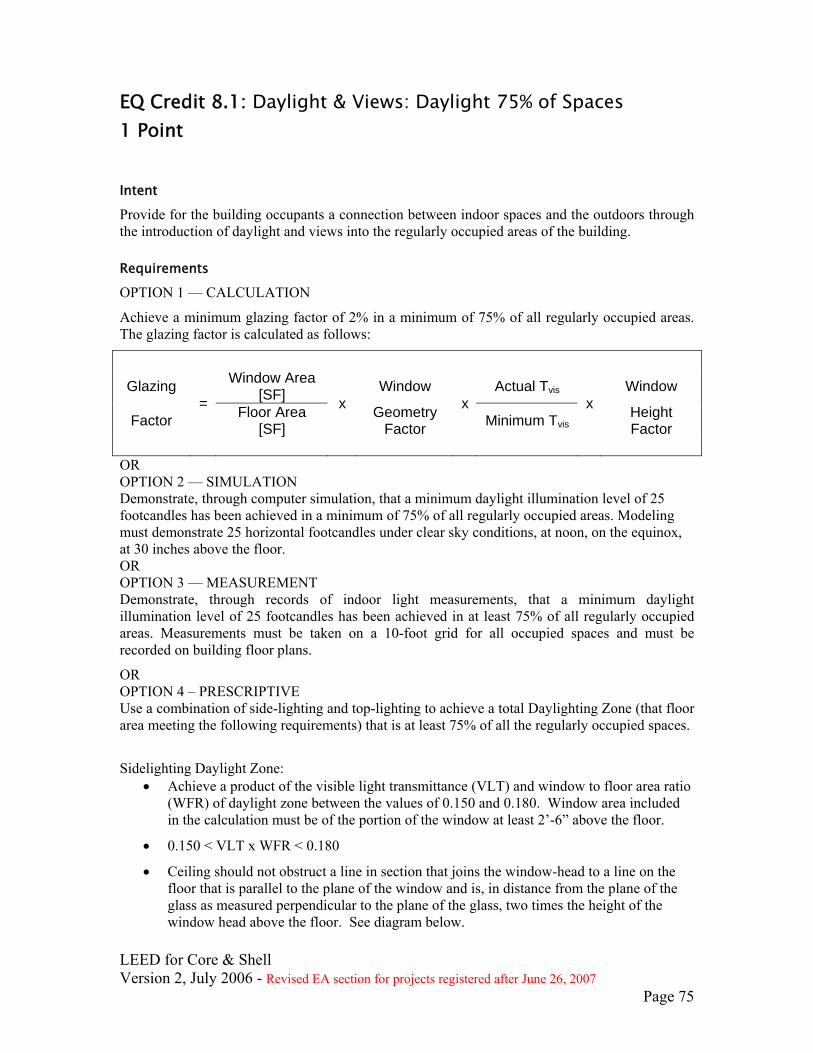
LEED for Core & Shell Version 2, July 2006 - Revised EA section for projects registered after June 26, 2007
Page 75
EQ Credit 8.1: Daylight & Views: Daylight 75% of Spaces 1 Point Intent
Provide for the building occupants a connection between indoor spaces and the outdoors through the introduction of daylight and views into the regularly occupied areas of the building.
Requirements
OPTION 1 — CALCULATION
Achieve a minimum glazing factor of 2% in a minimum of 75% of all regularly occupied areas. The glazing factor is calculated as follows:
Glazing Window Area
[SF] Window Actual Tvis Window
Factor = Floor Area
[SF]
x Geometry Factor
xMinimum Tvis
x Height Factor
OR OPTION 2 — SIMULATION Demonstrate, through computer simulation, that a minimum daylight illumination level of 25 footcandles has been achieved in a minimum of 75% of all regularly occupied areas. Modeling must demonstrate 25 horizontal footcandles under clear sky conditions, at noon, on the equinox, at 30 inches above the floor. OR OPTION 3 — MEASUREMENT Demonstrate, through records of indoor light measurements, that a minimum daylight illumination level of 25 footcandles has been achieved in at least 75% of all regularly occupied areas. Measurements must be taken on a 10-foot grid for all occupied spaces and must be recorded on building floor plans.
OR OPTION 4 – PRESCRIPTIVE Use a combination of side-lighting and top-lighting to achieve a total Daylighting Zone (that floor area meeting the following requirements) that is at least 75% of all the regularly occupied spaces.
Sidelighting Daylight Zone:
• Achieve a product of the visible light transmittance (VLT) and window to floor area ratio (WFR) of daylight zone between the values of 0.150 and 0.180. Window area included in the calculation must be of the portion of the window at least 2’-6” above the floor.
• 0.150 < VLT x WFR < 0.180
• Ceiling should not obstruct a line in section that joins the window-head to a line on the floor that is parallel to the plane of the window and is, in distance from the plane of the glass as measured perpendicular to the plane of the glass, two times the height of the window head above the floor. See diagram below.
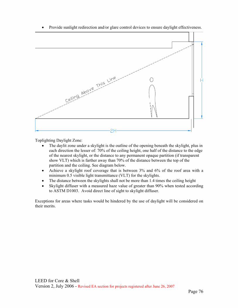
• Provide sunlight redirection and/or glare control devices to ensure daylight effectiveness.
Toplighting Daylight Zone:
• The daylit zone under a skylight is the outline of the opening beneath the skylight, plus in each direction the lesser of: 70% of the ceiling height, one half of the distance to the edge of the nearest skylight, or the distance to any permanent opaque partition (if transparent show VLT) which is farther away than 70% of the distance between the top of the partition and the ceiling. See diagram below.
• Achieve a skylight roof coverage that is between 3% and 6% of the roof area with a minimum 0.5 visible light transmittance (VLT) for the skylights.
• The distance between the skylights shall not be more than 1.4 times the ceiling height • Skylight diffuser with a measured haze value of greater than 90% when tested according
to ASTM D1003. Avoid direct line of sight to skylight diffuser. Exceptions for areas where tasks would be hindered by the use of daylight will be considered on their merits.
LEED for Core & Shell Version 2, July 2006 - Revised EA section for projects registered after June 26, 2007
Page 76
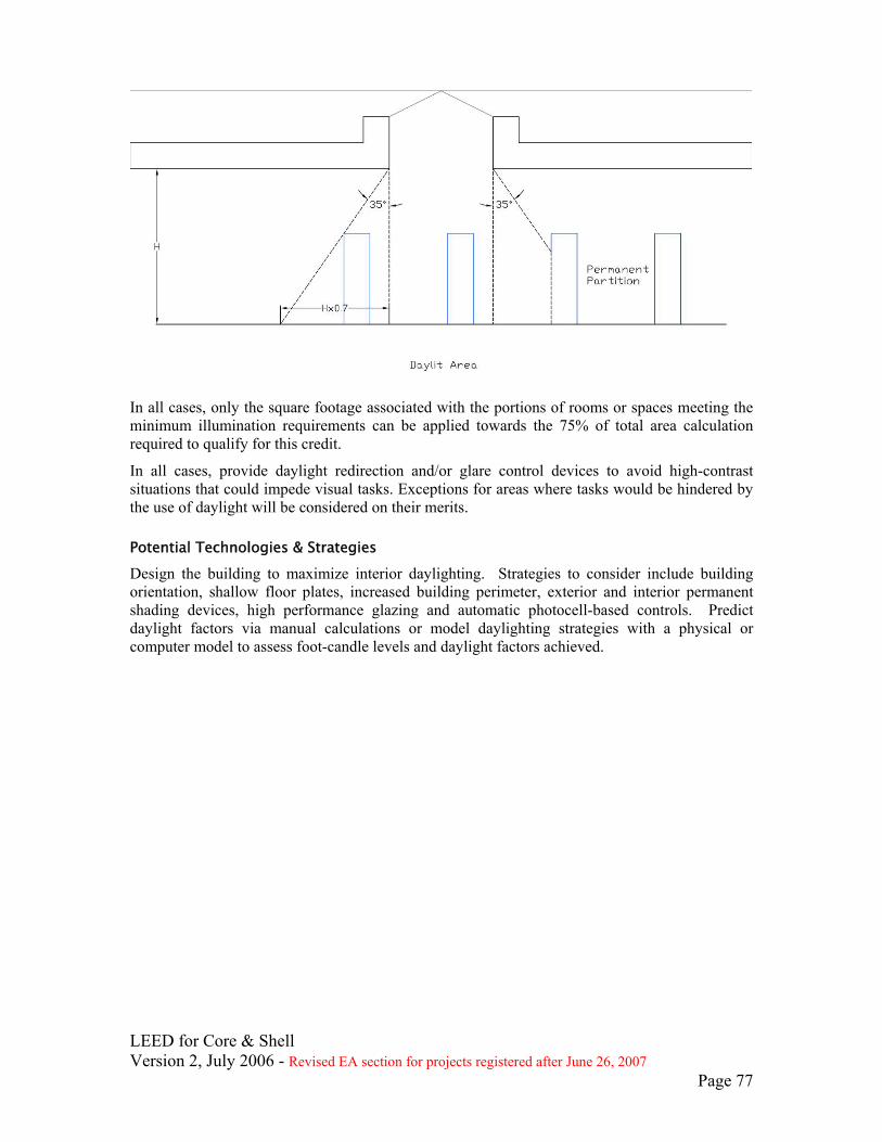
In all cases, only the square footage associated with the portions of rooms or spaces meeting the minimum illumination requirements can be applied towards the 75% of total area calculation required to qualify for this credit.
In all cases, provide daylight redirection and/or glare control devices to avoid high-contrast situations that could impede visual tasks. Exceptions for areas where tasks would be hindered by the use of daylight will be considered on their merits.
Potential Technologies & Strategies
Design the building to maximize interior daylighting. Strategies to consider include building orientation, shallow floor plates, increased building perimeter, exterior and interior permanent shading devices, high performance glazing and automatic photocell-based controls. Predict daylight factors via manual calculations or model daylighting strategies with a physical or computer model to assess foot-candle levels and daylight factors achieved.
LEED for Core & Shell Version 2, July 2006 - Revised EA section for projects registered after June 26, 2007
Page 77

LEED for Core & Shell Version 2, July 2006 - Revised EA section for projects registered after June 26, 2007
Page 78
EQ Credit 8.2: Daylight & Views: Views for 90% of Spaces 1 Point Intent
Provide for the building occupants a connection between indoor spaces and the outdoors through the introduction of daylight and views into the regularly occupied areas of the building.
Requirements
Achieve direct line of sight to the outdoor environment via vision glazing between 2'6" and 7'6" above finish floor for building occupants in 90% of all regularly occupied areas. Determine the area with direct line of sight by totaling the regularly occupied square footage that meets the following criteria:
• In plan view, the area is within sight lines drawn from perimeter vision glazing. • In section view, a direct sight line can be drawn from the area to perimeter vision glazing.
Line of sight may be drawn through interior glazing. For private offices, the entire square footage of the office can be counted if 75% or more of the area has direct line of sight to perimeter vision glazing. For multi-occupant spaces, the actual square footage with direct line of sight to perimeter vision glazing is counted. The core and shell design needs to develop a feasible tenant layout(s) per the default occupancy counts (or some other justifiable occupancy count) that can be used in the analysis of this credit.
Potential Technologies & Strategies
Design the space to maximize daylighting and view opportunities. Strategies to consider include lower partition heights, interior shading devices, interior glazing, and automatic photocell-based controls. Allow the tenant to design the space to maximize daylighting and view opportunities. Strategies to consider include lower partition heights, interior shading devices, interior glazing, and photo integrated light sensors. This credit requires consideration of tenant design for views that can be implemented during future tenant build-out. Core and shell design documents should include drawings or specifications that detail the design assumptions and information on how the tenant can use this capability. If Tenant Design and Construction Guidelines are created, this information should also be included in the guidelines.

LEED for Core & Shell Version 2, July 2006 - Revised EA section for projects registered after June 26, 2007
Page 79
Innovation & Design Process
ID Credit 1–1.4: Innovation in Design 1–4 Points Intent
To provide design teams and projects the opportunity to be awarded points for exceptional performance above the requirements set by the LEED for Core & Shell Green Building Rating System and/or innovative performance in Green Building categories not specifically addressed by the LEED for Core & Shell Green Building Rating System.
Requirements
Credit 1.1 (1 point) In writing, identify the intent of the proposed innovation credit, the proposed requirement for compliance, the proposed submittals to demonstrate compliance, and the design approach (strategies) that might be used to meet the requirements.
Credit 1.2 (1 point) Same as Credit 1.1
Credit 1.3 (1 point) Same as Credit 1.1
Credit 1.4 (1 point) Same as Credit 1.1
Potential Technologies & Strategies
Substantially exceed a LEED for Core & Shell performance credit such as energy performance or water efficiency. Apply strategies or measures that demonstrate a comprehensive approach and quantifiable environment and/or health benefits.
LEED for Core & Shell Version 2, July 2006 - Revised EA section for projects registered after June 26, 2007
Page 80
ID Credit 2: LEED Accredited Professional 1 Point
Intent
To support and encourage the design integration required by a LEED for Core & Shell green building project and to streamline the application and certification process.
Requirements
At least one principal participant of the project team shall be a LEED Accredited Professional (AP).
Potential Technologies & Strategies
Educate the project team members about green building design & construction and application of the LEED Rating System early in the life of the project. Consider assigning the LEED AP as a facilitator of an integrated design & construction process.
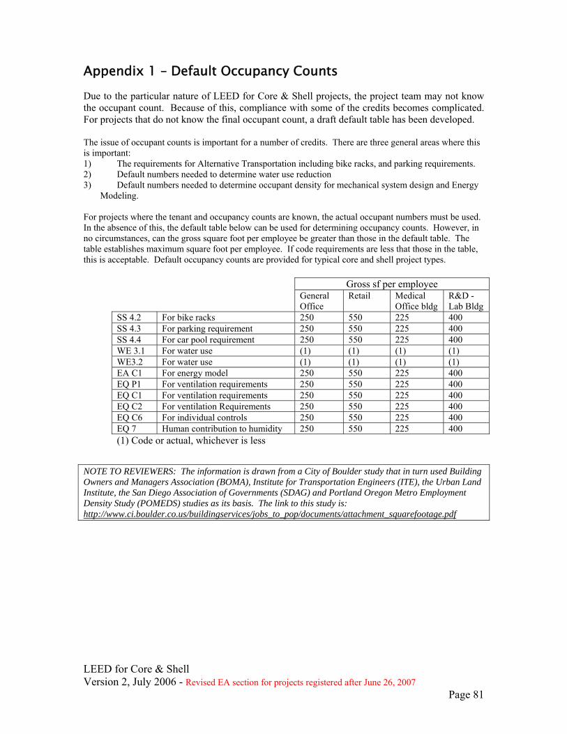
LEED for Core & Shell Version 2, July 2006 - Revised EA section for projects registered after June 26, 2007
Page 81
Appendix 1 – Default Occupancy Counts Due to the particular nature of LEED for Core & Shell projects, the project team may not know the occupant count. Because of this, compliance with some of the credits becomes complicated. For projects that do not know the final occupant count, a draft default table has been developed. The issue of occupant counts is important for a number of credits. There are three general areas where this is important: 1) The requirements for Alternative Transportation including bike racks, and parking requirements. 2) Default numbers needed to determine water use reduction 3) Default numbers needed to determine occupant density for mechanical system design and Energy
Modeling. For projects where the tenant and occupancy counts are known, the actual occupant numbers must be used. In the absence of this, the default table below can be used for determining occupancy counts. However, in no circumstances, can the gross square foot per employee be greater than those in the default table. The table establishes maximum square foot per employee. If code requirements are less that those in the table, this is acceptable. Default occupancy counts are provided for typical core and shell project types.
Gross sf per employee General
Office Retail Medical
Office bldg R&D -Lab Bldg
SS 4.2 For bike racks 250 550 225 400 SS 4.3 For parking requirement 250 550 225 400 SS 4.4 For car pool requirement 250 550 225 400 WE 3.1 For water use (1) (1) (1) (1) WE3.2 For water use (1) (1) (1) (1) EA C1 For energy model 250 550 225 400 EQ P1 For ventilation requirements 250 550 225 400 EQ C1 For ventilation requirements 250 550 225 400 EQ C2 For ventilation Requirements 250 550 225 400 EQ C6 For individual controls 250 550 225 400 EQ 7 Human contribution to humidity 250 550 225 400 (1) Code or actual, whichever is less
NOTE TO REVIEWERS: The information is drawn from a City of Boulder study that in turn used Building Owners and Managers Association (BOMA), Institute for Transportation Engineers (ITE), the Urban Land Institute, the San Diego Association of Governments (SDAG) and Portland Oregon Metro Employment Density Study (POMEDS) studies as its basis. The link to this study is: http://www.ci.boulder.co.us/buildingservices/jobs_to_pop/documents/attachment_squarefootage.pdf

LEED for Core & Shell Version 2, July 2006 - Revised EA section for projects registered after June 26, 2007
Page 82
Appendix 2 – Core & Shell Energy Modeling Guidelines These guidelines are intended to ensure that projects in different markets with different project teams are approaching the energy modeling requirements in a similar manner and that a minimum benchmark for energy optimization is established.
1. Create the ASHRAE 90.1-2004 baseline building model and proposed building model 1.1 Follow the ASHRAE 90.1-2004 Building Performance Rating Method. This is a
whole building model inclusive of both shell and core, and tenant space scope. The following describes the prescriptive requirements for developing the whole building modeling of both the known shell and core work and unknown tenant space development.
1.2 Tenant spaces are defined as meeting all the following conditions: 1.2.1 Components exclusively serve the tenant space; 1.2.2 Components specifically designed for the tenant space; 1.2.3 Energy using components are metered and apportioned and/or billed to
the tenant; 1.2.4 The tenant will pay for the components.
1.3 The core and shell building is all parts of the building that is not a tenant space. 2 Proposed Building Model
2.1 Core and Shell Building 2.1.1 HVAC Systems
2.1.1.1 Model the building system as described in the design documents. • If the HVAC system is not yet designed, use the same
HVAC system as the baseline model. 2.1.2 Building Envelope
2.1.2.1 Model the building envelope as shown on the architectural drawings. 2.1.3 Lighting
2.1.3.1 Model the lighting power as shown in the design documents for the core and shell spaces.
2.2 Tenant Spaces 2.2.1 Lighting
2.2.1.1 Model separate electric meters for the lighting in the core building and the tenant spaces.
2.2.1.2 Choose a space type classification for the building spaces. Use lighting levels shown in chart 9.3.1.2 of ASHRAE 90.1-2004 for the space type use classification.
• If the tenant lighting is designed and installed as part of the core and shell work, the project team may model the designed or installed lighting systems.
2.2.2 Receptacle and Other Loads 2.2.2.1 Model separate meters for tenant plug loads and process loads. 2.2.2.2 Use the following values to model tenant plug loads or provide
documentation for the modeled loads (See the Process energy section on page 44 of this section):
2.2.2.3 Computer intensive offices • 2.0 W/sq. ft.
2.2.2.4 General office areas • 1.5 W/sq. ft.
2.2.2.5 Large conference areas • 1.0 W/sq. ft.
2.2.2.6 Corridors

LEED for Core & Shell Version 2, July 2006 - Revised EA section for projects registered after June 26, 2007
Page 83
• 0 W/sq. ft. 2.2.2.7 Server/computer rooms
• 50 W/sq. ft. 2.2.2.8 Other uses
• Use diversity in calculations 3 Baseline Building Model
3.1 Core and Shell Building 3.1.1 HVAC system
3.1.1.1 Model the baseline building HVAC system determined from Table G3.1.1A in ASHRAE 90.1-2004.
3.1.2 Building Envelope 3.1.2.1 Comply with the prescriptive requirements of ASHRAE 90.1-2004.
3.1.3 Lighting 3.1.3.1 Model the lighting power in the core and shell areas as determined by
the space type classification in chart 9.6.1 of ASHRAE 90.1-2004. 3.2 Tenant Spaces
3.2.1 Lighting 3.2.1.1 Model separate electric meters for the lighting in the core building and
the tenant spaces. 3.2.1.2 Use the same lighting power as modeled in the proposed building.
3.2.2 Receptacle and other Loads 3.2.2.1 Model separate meters for tenant receptacle loads and process loads. 3.2.2.2 Use the same values for receptacle loads as used in the proposed
building. 4 Perform Energy Simulation of Baseline Building and Proposed Building
4.1 Simulate building performance for an entire year. 5 Compare Annual Energy Costs of Baseline Building and Proposed Building
5.1 From the simulation, determine the annual energy costs of the budget building and design building.
5.2 Verify that 25% of the overall energy cost is process load. 5.3 Determine the percentage savings for annual energy costs
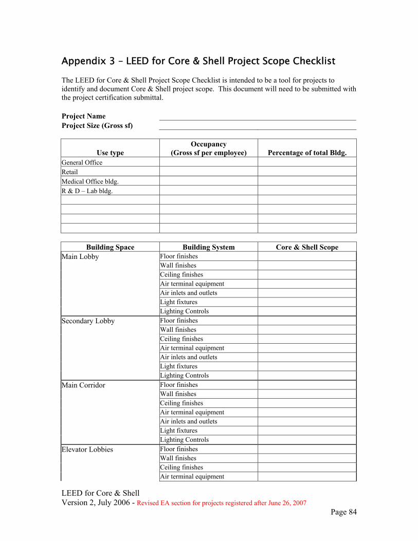
LEED for Core & Shell Version 2, July 2006 - Revised EA section for projects registered after June 26, 2007
Page 84
Appendix 3 – LEED for Core & Shell Project Scope Checklist The LEED for Core & Shell Project Scope Checklist is intended to be a tool for projects to identify and document Core & Shell project scope. This document will need to be submitted with the project certification submittal. Project Name Project Size (Gross sf)
Use type Occupancy
(Gross sf per employee) Percentage of total Bldg. General Office Retail Medical Office bldg. R & D – Lab bldg.
Building Space Building System Core & Shell Scope Main Lobby Floor finishes Wall finishes Ceiling finishes Air terminal equipment Air inlets and outlets Light fixtures Lighting Controls Secondary Lobby Floor finishes Wall finishes Ceiling finishes Air terminal equipment Air inlets and outlets Light fixtures Lighting Controls Main Corridor Floor finishes Wall finishes Ceiling finishes Air terminal equipment Air inlets and outlets Light fixtures Lighting Controls Elevator Lobbies Floor finishes Wall finishes Ceiling finishes Air terminal equipment
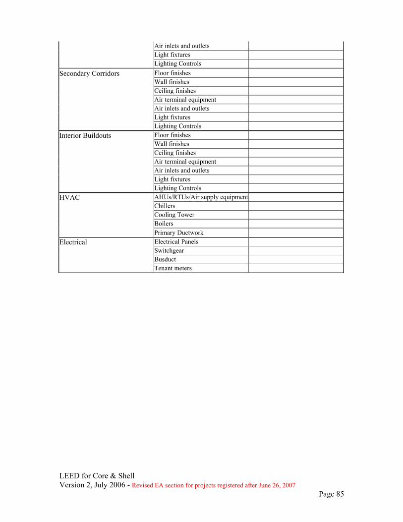
LEED for Core & Shell Version 2, July 2006 - Revised EA section for projects registered after June 26, 2007
Page 85
Air inlets and outlets Light fixtures Lighting Controls Secondary Corridors Floor finishes Wall finishes Ceiling finishes Air terminal equipment Air inlets and outlets Light fixtures Lighting Controls Interior Buildouts Floor finishes Wall finishes Ceiling finishes Air terminal equipment Air inlets and outlets Light fixtures Lighting Controls HVAC AHUs/RTUs/Air supply equipment Chillers Cooling Tower Boilers Primary Ductwork Electrical Electrical Panels Switchgear Busduct Tenant meters