ledger documentation hub · ledger documentation hub, release 1 note: this documentation is...
TRANSCRIPT
Ledger Documentation HubRelease 1
Aug 01, 2017

Background Information
1 Introduction 3
2 Personal Security Devices 5
3 The Master Seed 7
4 HD Key Generation 9
5 Applications of HD Trees 11
6 Application Isolation 15
7 Introduction 17
8 Overview 19
9 BOLOS Features 21
10 Hardware Architecture 27
11 Application Environment 31
12 Introduction 33
13 Getting Started 35
14 Interaction Between BOLOS and Apps 39
15 Application Structure and I/O 41
16 Display Management 43
17 Persistent Storage and PIC 45
18 Common Pitfalls and Troubleshooting 49
19 External Documentation 53
i

ii
Ledger Documentation Hub, Release 1
Note: This documentation is intended for developers only and not general users.
Ledger produces personal security devices such as the Ledger Nano S and the Ledger Blue, both of which are archi-tected around a Secure Element and the BOLOS platform.
This documentation contains information about developing apps for these devices, from high-level concepts like hier-archical deterministic key generation to low-level details about the hardware architecture of these devices.
Background Information 1

Ledger Documentation Hub, Release 1
2 Background Information
CHAPTER 1
Introduction
In this chapter, we’ll first provide some background information about personal security devices and hierarchicaldeterministic wallets. Then, we’ll introduce the application isolation technology that helps make Ledger devicessecure and open-source friendly.
3

Ledger Documentation Hub, Release 1
4 Chapter 1. Introduction

CHAPTER 2
Personal Security Devices
Personal security devices are designed to isolate cryptographic secrets (like PGP or Bitcoin private keys) from yourpotentially insecure computer which has known vulnerabilities. Storing cryptographic secrets on a physical mediumthat cannot be infected with a virus such as writing them on a piece of paper (or storing them on an encrypted drive)is secure until you need to use your funds. The instant you need to transfer your funds, you need to load your privatekeys onto your computer to sign the transaction and as such you expose them to potential malware (unless you’d liketo perform the cryptographic operations necessary to sign the transaction by hand, which is far from convenient, tosay the least). This is where personal security devices come in - they don’t just store your cryptographic secrets safely,they also allow you to perform operations with them (like signing transactions) securely and conveniently. Ledgerdevices also generate secrets securely with a large amount of entropy using an AIS-31 compliant true random numbergenerator (TRNG). As such, it is more secure to use the device’s internally generated secrets rather than importing asecret from elsewhere which could have been compromised before being loaded onto the device.
Ledger leverages Secure Element technology to build personal security devices for cryptocurrencies and blockchainswhich provide an interface between humans and the blockchain world. They keep your private keys secure fromhackers by storing them in a tamper-proof and eavesdropping-proof Secure Element. Additionally, the Ledger Nano Sand Ledger Blue have a screen which serves as a trusted source of information about your assets as it is controlled bythe device itself, not by potentially vulnerable computer software.
However, personal security devices aren’t intended to be a store of data - they’re a root of trust. Apps for these devicestend to be lightweight apps that work in conjunction with a host computer. The Secure Element places a limit on thestorage capacity of these devices, so storing data encrypted on a host computer is preferred over storing data directlyon the device. As such, the device contains a set of private keys that you can use to unlock your data and assets,without any risk of compromising the security of your assets in the event that your computer becomes infected with avirus. Applications that process large amounts of data may not be able to store all of the data on the device at once.There are two effective solutions to this problem: 1) stream data through the device while the application processesit (for example, it may be encrypting / decrypting the data) or 2) derive a secret on the device (preferably from themaster seed) and use it on the computer to process the data (this is how the PGP app works).
This is an important concept: personal security devices are a secure portal to your assets, not a bank. If your devicegets lost or destroyed, your assets are still safe. The key to this portal is your “master seed”. That brings us to our nextsection, The Master Seed.
5

Ledger Documentation Hub, Release 1
6 Chapter 2. Personal Security Devices

CHAPTER 3
The Master Seed
Applications running on Ledger personal security devices are designed to be lightweight and easily recoverable.Ledger achieves both of these goals by using hierarchical deterministic key generation. Hierarchical determin-istic key generation is used by applications to derive a theoretically infinite number of cryptographic secrets from asingle master seed. In this way, your cryptocurrency private keys, passwords, and other cryptographic secrets can allbe determined and intrinsically “stored” in a single master seed. Because of this, the device’s apps don’t have to storetheir own private keys, because they can all be generated on-demand by the device from the master seed. This meansthat if your device is lost, destroyed, or reset then all you need is your master seed to recover your secrets. In addition,an application that supports this scheme can be deleted and reinstalled without losing any secure data or assets. Yourmaster seed is randomly generated for you when you first set up your Ledger device, and then you just need to write itdown to allow you to recover your device in the future.
Generation and Serialization
The master seed is the key to your cryptographic secrets. As such, the master seed should be something that is longand nearly impossible for anyone to guess. Your master seed isn’t like a password or a PIN (Ledger devices alreadyhave PINs to protect access to them), instead it’s the root of all of your cryptographic secrets. You only need to accessit when you first write it down on paper when your device randomly generates it for the first time, or in the future ifyou have to recover your device.
Ledger uses a standard called BIP 39 for the generation and interpretation of the master seed on all of our devices. BIP39 is an industry standard used by many other hierarchical deterministic wallets. The exact type of BIP 39 seed usedby Ledger devices by default is a 24-word mnemonic that consists of only the 2048 words from the BIP 39 Englishwordlist. Here’s how a BIP 39 24-word mnemonic seed is generated:
1. The device generates a sequence of 256 random bits using the true random number generator (TRNG) built intothe device’s Secure Element.
2. The first 8 bits of the SHA-256 hash of the initial 256 bits is appended to the end, giving us 264 bits.
3. All 264 bits are split into 24 groups of 11 bits.
4. Each group of 11 bits is interpreted as a number in the range 0 - 2047, which serves as an index to the BIP 39wordlist, giving us 24 words.
7

Ledger Documentation Hub, Release 1
The result of this process is that your device will generate a single mnemonic seed out of 2256 possible mnemonicseeds (That’s one of 115 792 089 237 316 195 423 570 985 008 687 907 853 269 984 665 640 564 039 457 584 007913 129 639 936 possible mnemonic seeds). Note that while the first 23 words are completely random, the final wordwas derived from 3 random bits and 8 calculated bits from the SHA-256 hash. This means that the final word canact like a checksum - if you input an incorrect seed into the device while recovering it, it is possible for the device todetect that the inputted seed is invalid.
Note: Can someone guess my seed? There are 2256 different possible 24-word mnemonic seeds. For comparison,the number of atoms on Earth is estimated to be around 2166. Just let that sink in for a second. The chance of someoneelse being able to guess your seed is astronomically small, to say the least.
But all we have here is a sequence of 24 words, how can the device use this as a cryptographic secret?
After the 24-word mnemonic is generated, it has to be converted into a binary seed by the device (this process is calledserialization). This is done using the PBKDF2-HMAC-SHA512 key derivation function to convert your mnemonicseed and an optional passphrase of your choosing into a 512 bit binary seed. This BIP 39 passphrase can be set onyour device through the Settings menu, and it can be changed at will without resetting your device (in fact, you canhave multiple passphrases loaded onto the device at once if you wish). By changing the passphrase, the resulting 512bit binary seed is completely changed.
This 512 bit binary seed is the root of your device’s cryptographic secrets. Every cryptographic secret that your deviceneeds (cryptocurrency private keys & addresses, passwords, etc.) can be derived from this 512 bit binary seed. We’llexplore how an infinite number of cryptographic secrets can be derived from this one seed in the next section, HD KeyGeneration.
8 Chapter 3. The Master Seed
CHAPTER 4
HD Key Generation
In the previous section we discussed how Ledger devices use a master 24-word mnemonic seed to derive a theoreticallyinfinite number of cryptographic secrets. Though it might seem impossible at first glance, this can be done usingnothing more than some mathematical sorcery. The process used to do this is called hierarchical deterministic (HD)key generation.
The process for HD key generation used by all Ledger devices (and many other HD wallets) is defined by BIP 32.
Here’s how it works.
The Master Node
Hierarchical deterministic key generation involves creating a theoretically infinite tree of cryptographic secrets. Theroot of this tree from which everything is generated is called the master node. The master node is derived directly fromthe master binary seed described in the previous section using HMAC-SHA512. The master node of your wallet is allthe information you need to access an infinite hierarchy of private keys. As such, you should take good care to keepyour mnemonic seed safe.
Passphrases
Passphrases are a standard feature of BIP 39 supported by many HD wallets. Passphrases are an optional way ofadding additional data to the master seed before deriving the master node of the HD wallet. By specifying a differentpassphrase (or no passphrase at all), the value of the master node is completely changed. As you will discover as youread the rest of this section, changing the master node of the HD wallet completely changes all of the informationderived from it (for example, your Bitcoin addresses). In this way, you can keep the same master seed on a device, butuse different passphrases to access completely unique, separated wallets.
9

Ledger Documentation Hub, Release 1
An Infinite Tree
Descending from the master node is a tree of an infinite number of private keys. All you need to determine a particularkey is the master node (your mnemonic seed) and the location of the key in the tree (called its “path”). This tree iscreated using an incredibly powerful algorithm defined by BIP 32 called the CKD function. All you need to knowabout this magical algorithm is that it can be used to calculate any node on the HD tree given the node’s position andthe value of the master node. Essentially, the CKD function is applied to the master node a number of times in orderto “scramble” its bits and output a brand new node. This algorithm is magical because it is impossible to reverse.Given a private key on your tree, it is impossible to go backwards up the tree and determine your master node.1
Child Key Derivation Function
The HD tree is made up of “nodes”. Using the CKD function, many “child” nodes can be derived from a single“parent” node. Each node contains three pieces of information: a private key, a public key, and a chain code. In thecase of a cryptocurrency wallet, the private key is the part that is used to sign transactions and the public key is usedto generate the corresponding cryptocurrency address. The node’s chain code is an extra little bit to prevent someonefrom determining the children of a node using only the node’s public and private keys.
The CKD function has been designed in a way that provides great flexibility in the way child nodes are derived.Specifically, instead of requiring the public key, private key, and chain code to derive a child node, the CKD functioncan be used to derive child public keys from the parent public key and child private keys from the parent private key.Additionally, BIP 32 defines the concept of “hardened” child nodes. If a child node is “hardened”, then its public keycannot be determined from its parent node’s public key.
These are the transformations that the CKD function can perform:
• parent private key & chain code child private key & chain code
• parent public key & chain code child public key & chain code (unless the child node is hardened)
• parent private key & chain code child public key & chain code
Note that it is impossible to derive a child private key from a parent public key. This model has some interestingconsequences, mainly that the parent public key and chain code can be shared which allows someone to derive allchild public keys (unless the child nodes are hardened), but no private keys.
For example, this model can be used to facilitate the process of auditing an HD wallet. By sharing the public keyand chain code of all accounts in an HD wallet, one can give an auditor the ability to view all addresses in the wallet(without having the associated private keys). As such, the auditor could determine what money is going where, withouthaving access to any private keys, meaning the auditor couldn’t sign any transactions. We’ll talk about what “accounts”are in the next section.
For a more detailed list and explanation of some of the use-cases made possible by this model, see this section of theBIP 32 specification.
In the next section, Applications of HD Trees, we’ll talk about how all of these features are used by HD wallets andother applications.
Tip: If you’d like to play with BIP 39 mnemonics or BIP 32 derivation on a computer, take a look at this tool:https://iancoleman.github.io/bip39/.
1 Technically it isn’t impossible to determine a node given the child node and the corresponding index, but there is no known attack to do thisfaster than a properly executed brute-force attack. See this section of BIP 32 for details.
10 Chapter 4. HD Key Generation

CHAPTER 5
Applications of HD Trees
In the previous section, HD Key Generation, we described how an infinite number of cryptographic secrets can begenerated from a single master seed. In this section, we’ll talk about how Ledger applies this concept to developapplications for our personal security devices that are lightweight and easily recoverable.
Coin Types
So how are HD trees useful? Simple: developers of different cryptocurrencies got together and reserved a space onthe tree. Developers for these cryptocurrencies each specified which “location” on the tree they wanted users to storetheir private keys (called the coin’s “path”). This path is public information, because nobody can determine the actualvalue of your keys without knowing your master node (your mnemonic seed). The paths that correspond to variouscryptocurrencies, and the paths used to derive cryptocurrency addresses and private keys, are defined by BIP 44 (whichin turn defers coin type registration to SLIP 44).
For each cryptocurrency, there is a node on the tree where all of the keys for that coin begin (from this point on, we’llcall this the “coin type root node”, for lack of a better term). Since this is a hierarchical deterministic tree, we canapply the same rules to that coin type root node as we applied to the master node. Just as an infinite tree of keysdescended from the master node, there is also an infinite tree of keys descending from the coin type root node. Thismeans that if you have a 24-word mnemonic seed, even if you don’t use Bitcoin, you have a virtually infinite1 numberof Bitcoin addresses. You have a virtually infinite number of Ethereum addresses, too.
Warning: In the Ledger Ethereum Wallet desktop app, addresses are not derived according to BIP 44. Insteadof using the derivation path m / 44' / 60' / account' / change / address_index (as definedby BIP 44 for Ethereum), the Ledger Ethereum Wallet desktop app uses the derivation path m / 44' / 60' /0' / address_index.
1 In this case, virtually infinite = 263 = 9 223 372 036 854 775 808.
11

Ledger Documentation Hub, Release 1
How does my wallet know which addresses I’ve used?
In most BIP 44-compliant HD wallet programs (including the Ledger Bitcoin Wallet desktop app) your addresses aresplit into “accounts”. You can split your coins across multiple accounts in the same way you might with multiple bankaccounts. You can have an account for savings, an account for donations, an account for common expenses, et cetera.Within each of these accounts, there are two virtually infinite “chains” of addresses: an external chain and an internalchain (commonly called the “change address” chain). Each of the addresses in these chains are given numbers (calledthe “address index”) starting at 0.
When your wallet software starts up for the first time, it searches the blockchain for transactions involving addressnumber 0 for each address chain. If it finds any transactions, then the address is displayed by the wallet softwareand the wallet searches for transactions involving address number 1. This process continues until the wallet finds anaddress that you haven’t used yet. It displays this address to you, then stops searching for more addresses in the chain,making the assumption that no more of them have been used yet.2
In this way, all of the important information about your transaction history is stored in the blockchain, so none of it hasto be stored in the hardware wallet itself. If your wallet is destroyed / reset, all you need to do is input your 24-wordmnemonic seed into a new HD wallet and the wallet will search the public blockchain for all of the information itneeds.
Summary
An HD wallet has a few very important properties, so let’s reiterate:
• The “tree” that makes up an HD wallet is generated using nothing more than your 24-word mnemonic seed.This is all you need to generate all of your cryptocurrency addresses, and sign transactions.
• No private keys need to be saved, anywhere. Even if you continue to receive Bitcoins to more and more of youraddresses, you don’t need to save any of those private keys anywhere. This is because they were there all along,in the HD tree.
• The HD wallet standards used by Ledger (BIPs 32, 39, and 44) are industry standards. Your 24-word mnemonicseed will work with any other HD wallet that supports these standards, not just with Ledger wallets.
Going Beyond Cryptocurrencies
Hierarchical deterministic wallets are useful for a lot more than just securing assets on blockchains. You could alsoexpand this concept and use your master seed to derive passwords, PGP keys, SSH keys, et cetera.
For example, Ledger is currently developing a Password Manager app. It is currently available for the Ledger Nano Sin an early alpha form by clicking “show developer items” in the Ledger Manager.
The password manager app works by converting a node on the HD tree into a text password that looks like randomgibberish. When you create a new password, you must enter a label for the password (for example: “Google”,“Dropbox”, “Twitter”, etc.). The location of a password’s node on the HD tree is encoded in the correspondingpassword’s label. When you ask the Password Manager app for your password, it uses the password’s label to locatea specific node on the HD tree, and then it converts that node into a text password. You cannot specify your ownpasswords to use, the passwords are generated for you.
2 In this example, we described a wallet that operates with a gap limit of 1. Different wallet software use different values, but BIP 44 currentlyrecommends a gap limit of 20.
12 Chapter 5. Applications of HD Trees

Ledger Documentation Hub, Release 1
Fig. 5.1: A diagram of a hierarchical deterministic wallet; everything in the box labelled “hierarchical deterministictree” is recoverable if your wallet is lost, destroyed, or reset because it is all derived from the master seed
5.4. Going Beyond Cryptocurrencies 13

Ledger Documentation Hub, Release 1
14 Chapter 5. Applications of HD Trees

CHAPTER 6
Application Isolation
So how do I know that the apps I’m running on my Ledger Nano S are doing what I intend them to do? What protectsme from getting a virus on my Ledger Nano S?
Ledger solves these problems by utilizing the application isolation technology available in the Secure Element - theARM Memory Protection Unit and Operating Modes. The Memory Protection Unit is used to natively isolate eachapp to its own memory region, and apps run in User mode whereas the operating system runs in Supervisor mode. Byrestricting the device to a single-task model where only one app can run at a time, and each app is isolated from therest of the device, apps are prevented from accessing your cryptographic secrets on the device unless you explicitlygive them permission to.
The access that applications have to cryptographic secrets managed by the operating system can be configured whenloading an application onto the device. Instead of accessing secrets like the device’s master seed directly, applicationsinstead have to request the operating system to derive a node from the master seed by providing the operating systemwith a path to the requested node. When the application is loaded, the BIP 32 paths that the application is permittedto derive nodes from are specified. If the application requests the operating system to derive a node on a path that itis not permitted to use, the request is denied. In this way, many different applications can be loaded onto the device,and each of them can be restricted to a specific subtree of the HD tree depending on the application’s purpose. Thisprocess of requesting the operating system to perform an operation as Supervisor is called a syscall, and we’ll discussit further in later sections.
Still, the importance of only installing apps that you can trust should not be understated. In the next section, we’ll talkabout how Ledger’s operating system provides attestation features that allow the device to verify the authenticity ofthe apps that you’re installing by checking a digital signature that is sent along with apps when they’re loaded ontothe device. Additionally, we’ll discuss how Ledger’s platform is open-source friendly which enables you to review theapps that you’re using to manage your assets.
15

Ledger Documentation Hub, Release 1
16 Chapter 6. Application Isolation
CHAPTER 7
Introduction
This chapter contains detailed documentation about the core features offered by BOLOS, and how they can be utilizedby BOLOS applications and end-users. We’ll discuss how BOLOS manages the master device seed and the deviceprivate key, and how it can be used for attestation purposes. We’ll also describe the hardware architecture that iscommon between all BOLOS devices.
17

Ledger Documentation Hub, Release 1
18 Chapter 7. Introduction
CHAPTER 8
Overview
The operating system behind all Ledger personal security devices is called the Blockchain Open Ledger OperatingSystem, or BOLOS for short. BOLOS provides a lightweight, open-source framework for developers to build sourcecode portable applications that run in a secure environment. BOLOS is a way of turning hardware wallets into fullyfledged personal security devices.
BOLOS allows users to review and install applications that let them do more with their cryptographic secrets, whileprotecting the device and other applications from malicious code. The key to BOLOS’s open-source friendliness andability to limit the exposure of user’s cryptographic secrets to their apps is its application isolation technology.
BOLOS is organized into the following modules:
• An input / output module which allows applications executing in a secure environment to communicate with theoutside world and third party peripherals
• A cryptography module that implements low level cryptographic primitives and provides access to hardwareacceleration where available
• A persistent storage module that lets applications store data securely on the device
• A personalization module for interfacing with the device master seed
• An endorsement & application attestation module allowing BOLOS applications to provide proof of execution
• A user interface module for rendering the GUI and handling user input (eg. via buttons on the device)
The Dashboard
All BOLOS devices have a special app installed that runs on the OS with certain special privileges called the Dashboardapplication or the PSD Content Manager. The dashboard app contains the main GUI that the user sees when they aren’tin any other app. This is what the users use to enter their master seed, and its what they use to launch other applications.The dashboard application is also what the host computer communicates with when loading or deleting apps off of thedevice.
An important component of the dashboard is the BOLOS UX, which is the implementation of the device-wide userinterface that all applications need to interface with for certain device-wide UI features (like screen locking). The UI
19

Ledger Documentation Hub, Release 1
of the default dashboard app that is built into the firmware for the Nano S is also available as an external applicationthat can be loaded onto the device on GitHub.
20 Chapter 8. Overview
CHAPTER 9
BOLOS Features
In this section, we’ll discuss some of the features that are built into BOLOS. These features are available through thedashboard app and / or can be utilized by userspace applications.
Management of Cryptographic Secrets
There are two important cryptographic secrets that are stored and managed by BOLOS that will be discussed inthis section: the Device keypair (which is generated in-factory) and the BIP 32 master node (which is derived fromthe user’s BIP 39 mnemonic seed). Both of these secrets are stored by BOLOS and are not directly accessible toapplications for security reasons. The Device keypair can be used indirectly by applications for purposes of applicationattestation. Applications can derive secrets from the BIP 32 master node using a system call to BOLOS, provided theapp was given the appropriate permissions when loaded onto the device.
Passphrases in BOLOS
Since firmware version 1.3 on the Ledger Nano S, BOLOS allows users to load multiple BIP 39 passphrases onto thedevice at once. As described in the previous chapter, passphrases are a method to add additional entropy to the BIP 39master seed in order to completely change the HD tree. Users can set a temporary passphrase which is activated untilthe device is disconnected, or store a passphrase on the device by attaching it to a PIN. When a passphrase is attachedto a PIN, it is only activated when the user unlocks the device using the PIN corresponding to that passphrase. See ourKnowledge Base article on the advanced passphrase options for more information about using passphrases.
When a passphrase is activated, the binary seed derived according to BIP 39 is changed and as such the entire HD treeis changed. This means that using a different passphrase causes applications that derive information from the HD tree(like cryptocurrency wallet applications) to derive entirely different information (different cryptocurrency addresseswill be generated).
21

Ledger Documentation Hub, Release 1
Attestation
Attestation is a process used by Ledger devices to prove that they are a genuine Ledger device, and not a knock-offor fake version. It can be used by BOLOS when connecting to a host computer to prove that the device has not beentampered with. It can also be used by applications to prove that they are running on a genuine Ledger device. BOLOSalso supports endorsement of the device by third parties (called Owners) for attestation purposes.
Anti-Tampering with Attestation
Ledger devices are protected from interdiction attacks (being tampered with while en route from Ledger’s warehousesto your home) due to anti-tampering technology built into the firmware. Using attestation, the authenticity of thedevice is verified in software every time you plug it in to one of the Ledger Chrome applications.
When all Ledger devices are provisioned in the factory, they first generate a unique Device public-private keypair. TheDevice’s public key is then signed by Ledger’s Issuer key to create an Issuer Certificate which is stored in the device.This certificate is a digital seal of authenticity of the Ledger device. By providing the Device’s public key and IssuerCertificate, the device can prove that it is a genuine Ledger device.
When the Ledger device connects to one of the Ledger Chrome applications, the device uses the Issuer Certificate toprove that it is an authentic device (this takes place during establishment of the Secure Channel, as we’ll discuss laterin this section). If an attacker created a clone of the device running rogue firmware, this attestation process would failand the device would be rejected as non-genuine. It is impossible for an attacker to replace the firmware on the deviceand have it pass attestation without having a Device private key and the corresponding Issuer Certificate, signed byLedger.
It is incredibly unlikely for the Device private key to become compromised, because the Secure Element is designedto be a stronghold against such physical attacks. It is theoretically possible to extract the private key, but only withgreat expense and time, so only an organization such as the NSA could do it.
Tip: For more information about the benefits of Ledger’s use of a Secure Element for verifying device authenticity, seeour blog post How to protect hardware wallets against tampering (though keep in mind that not all of the informationin this article applies to Ledger’s latest products).
22 Chapter 9. BOLOS Features

Ledger Documentation Hub, Release 1
Endorsement & Application Attestation
As discussed in the previous subsection, the Device private key can be used to prove authenticity of a Ledger device.However, direct access to the device private key is limited to BOLOS and the privileged dashboard application,so it can’t be directly utilized by individual applications on the device (to avoid compromising the key). However,applications can indirectly use the Device private key for attestation purposes by generating attestation keypairs.
Attestation keypairs can be generated on demand by the user for applications to use. An attestation key can be setupusing the endorsementSetup.py or endorsementSetupLedger.py Python loader scripts. When generating an attestationkeypair, the host computer connects to the dashboard application and initiates a Secure Channel before instructing thedevice to create an attestation keypair. The device generates a new attestation keypair and signs it using the Deviceprivate key to create a Device Certificate. The device then returns the attestation public key, the Device Certificate,and the Issuer Certificate over the Secure Channel to the host. The host, which may be Ledger or a third party, thensigns the attestation public key with an Owner private key, thus creating an Owner Certificate which is sent back overthe Secure Channel and stored by the device (in this way, the Owner “endorses” the authenticity of the device). Thedevice can then prove that the attestation key belongs to a genuine Ledger device using the Device Certificate and theIssuer Certificate, and that the attestation key is trusted by the Owner using the Owner Certificate.
The attestation keys are not accessible to apps directly, instead BOLOS provides attestation functionality to userspaceapplications through cryptographic primitives available as system calls. There are two different Endorsement Schemesavailable to applications (Endorsement Scheme #1 and Endorsement Scheme #2). When creating an attestation key-pair, the user must choose which scheme the keypair shall belong to. Applications can then use that keypair by usingthe cryptographic primitives offered for the appropriate Endorsement Scheme.
Endorsement Scheme #1 offers two cryptographic primitives:
os_endorsement_key1_get_app_secret(...) Derive a secret from the attestation private key and thehash of the running application.
os_endorsement_key1_sign_data(...) Sign a message concatenated with the hash of the running appli-cation using the attestation private key (this signature can be verified using verifyEndorsement1.py).
Endorsement Scheme #2 offers a single cryptographic primitive:
os_endorsement_key2_derive_sign_data(...) Sign a message using a private key derived from theattestation private key and the hash of the running application (this signature can be verified using verifyEn-dorsement2.py).
For an example of how these features may be used, check out blue-app-otherdime and this blog post which discussesthe app in detail.
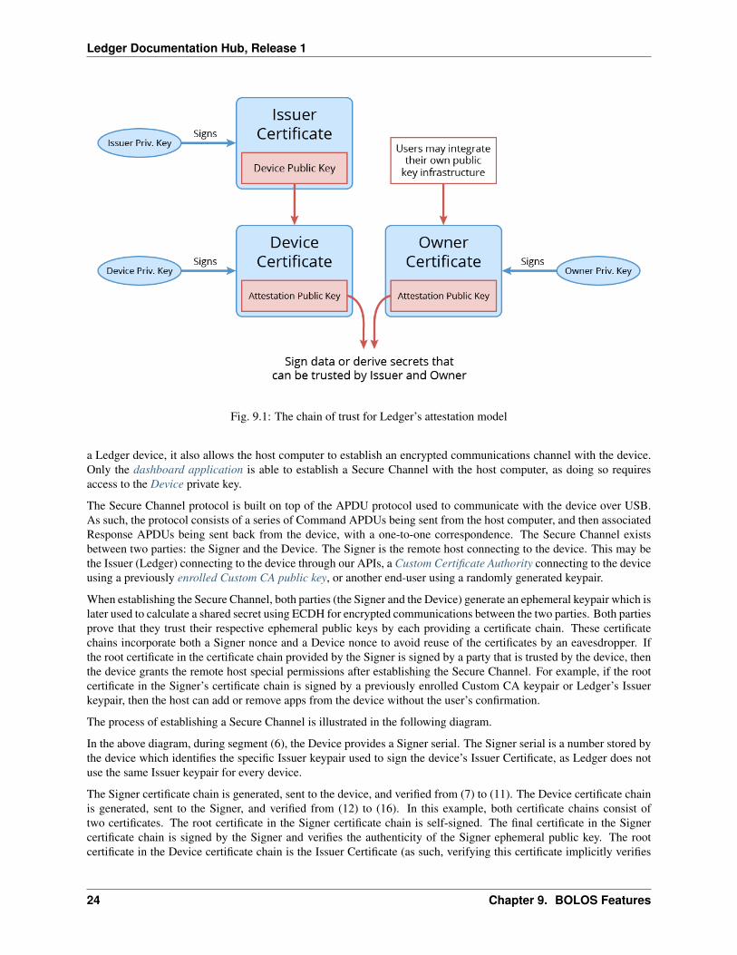
Attestation Chain of Trust
This diagram shows the chain of trust of our attestation model. All data signed by the attestation keys can be trusted tohave been signed by an authentic Ledger device. This is because the Device Certificate is proof that the attestation keysbelong to a device, and the Issuer Certificate is proof that the device is genuine. Additionally, the Owner Certificate isproof that the attestation keys are trusted by Owner (which may be Ledger or a third party).
Secure Channel
Throughout the standard device lifecycle, it is possible for a host computer to establish a Secure Channel with a deviceto verify its authenticity and to securely exchange secrets with it.
As discussed in Anti-Tampering with Attestation, the authenticity of a Ledger device can be verified when it connectsto a host computer by requesting the device’s Issuer Certificate, which is signed by Ledger. This is done when estab-lishing a Secure Channel with the device. However, the Secure Channel is not only a means to verify the authenticity of
9.3. Secure Channel 23
Ledger Documentation Hub, Release 1
Fig. 9.1: The chain of trust for Ledger’s attestation model
a Ledger device, it also allows the host computer to establish an encrypted communications channel with the device.Only the dashboard application is able to establish a Secure Channel with the host computer, as doing so requiresaccess to the Device private key.
The Secure Channel protocol is built on top of the APDU protocol used to communicate with the device over USB.As such, the protocol consists of a series of Command APDUs being sent from the host computer, and then associatedResponse APDUs being sent back from the device, with a one-to-one correspondence. The Secure Channel existsbetween two parties: the Signer and the Device. The Signer is the remote host connecting to the device. This may bethe Issuer (Ledger) connecting to the device through our APIs, a Custom Certificate Authority connecting to the deviceusing a previously enrolled Custom CA public key, or another end-user using a randomly generated keypair.
When establishing the Secure Channel, both parties (the Signer and the Device) generate an ephemeral keypair which islater used to calculate a shared secret using ECDH for encrypted communications between the two parties. Both partiesprove that they trust their respective ephemeral public keys by each providing a certificate chain. These certificatechains incorporate both a Signer nonce and a Device nonce to avoid reuse of the certificates by an eavesdropper. Ifthe root certificate in the certificate chain provided by the Signer is signed by a party that is trusted by the device, thenthe device grants the remote host special permissions after establishing the Secure Channel. For example, if the rootcertificate in the Signer’s certificate chain is signed by a previously enrolled Custom CA keypair or Ledger’s Issuerkeypair, then the host can add or remove apps from the device without the user’s confirmation.
The process of establishing a Secure Channel is illustrated in the following diagram.
In the above diagram, during segment (6), the Device provides a Signer serial. The Signer serial is a number stored bythe device which identifies the specific Issuer keypair used to sign the device’s Issuer Certificate, as Ledger does notuse the same Issuer keypair for every device.
The Signer certificate chain is generated, sent to the device, and verified from (7) to (11). The Device certificate chainis generated, sent to the Signer, and verified from (12) to (16). In this example, both certificate chains consist oftwo certificates. The root certificate in the Signer certificate chain is self-signed. The final certificate in the Signercertificate chain is signed by the Signer and verifies the authenticity of the Signer ephemeral public key. The rootcertificate in the Device certificate chain is the Issuer Certificate (as such, verifying this certificate implicitly verifies
24 Chapter 9. BOLOS Features

Ledger Documentation Hub, Release 1
Fig. 9.2: An admittedly not-so-simple diagram of the Secure Channel protocol handshake
9.3. Secure Channel 25
Ledger Documentation Hub, Release 1
the authenticity of the device). The final certificate in the Device certificate chain is signed by the Device and verifiesthe authenticity of the Device ephemeral public key.
Custom CA Public Key Enrollment
Custom Certificate Authorities have the option to generate a keypair (using genCAPair.py) and enroll their public keyonto the device (using setupCustomCA.py). Enrolling the Custom CA public key onto the device gives them thefollowing special privileges:
• The Custom CA can open authenticated Secure Channels with the device (using the --rootPrivateKeyoption of the Python loader scripts).
• The Custom CA can sign applications (using signApp.py) to create a signature which can be used to avoid theuser confirmation when loading the app on the device.
This feature may be used by BOLOS application developers to simplify the development process, but it is intended tobe much wider in scope than that. This feature may also be used by third party companies to give their own applicationmanager permissions to manage the device without needing user confirmation on every action.
Parties Involved in our Model
Below is a definition of all of the parties involved in our public key cryptography model.
Device
Device Certificate The meaning of this term should be quite self-evident, however in our public key cryptographymodel it has a distinct meaning. Each Device has a unique public-private keypair that is known only to thatdevice. In the factory, the Device generates it’s own public-private keypair. The Device’s private key is notknown by Ledger. The Device public-private key pair can be used to sign certificates.
Issuer
Issuer Certificate The Issuer is the party that initially provisions the Device. This party is always Ledger. The Issuerhas a public-private keypair that can be used to sign Issuer Certificates. Note that Ledger uses multiple Issuerkeypairs, not just one.
Owner
Owner Certificate An Owner is simply a party that owns and / or verifies the authenticity of a Ledger device. AnOwner has a public-private keypair that can be used to sign certificates. A single Device can have zero or moreOwners, and the Owner doesn’t have to be Ledger. The device uses Owner Certificates exclusively for thepurposes of application attestation.
Custom CA
Custom CA Certificate A Custom Certificate Authority has a public-private keypair, where the public key is enrolledon the device. The Custom CA’s private key can then be used to establish authenticated Secure Channels withthe device and sign applications.
A Custom CA may be a BOLOS application developer or a third party company that would like to give theirapplication manager special administration permissions with a BOLOS device.
26 Chapter 9. BOLOS Features

CHAPTER 10
Hardware Architecture
Ledger devices have a very unique architecture in order to leverage the security of the Secure Element while still beingable to interface with many different peripherals such as the screen, buttons, the host computer over USB, or Bluetooth& NFC in the case of the Ledger Blue. In order to accomplish this, we attached an additional STM32 microcontroller(“the MCU”) to the Secure Element (“the SE”) which acts as a “dumb router” between the Secure Element and theperipherals. The microcontroller doesn’t perform any application logic and it doesn’t store any of the cryptographicsecrets used by BOLOS, it simply manages the peripherals and notifies the Secure Element whenever new data isready to be received. BOLOS applications are executed entirely on the Secure Element. In this section, we’ll take alook at the hardware architecture to better embrace the hardware related constraints before analyzing their softwareimplications.
Multiple Processors: Secure Element Proxy
BOLOS is split between two hardware chips, one being secure (the ST31 Secure Element), and the other having JTAGenabled and acting as a proxy (the STM32 MCU).
Furthermore, the Secure Element is also split into two parts: the firmware which is under NDA and is therefore closed-source, and the SDK & application-loaded code which is open source friendly. The BOLOS firmware is responsiblefor low-level I/O operations and implements the SE-MCU link (though the handling of the protocol between the SEand the MCU is done by the currently running app).
BOLOS relies on the collaboration of both chips to empower Secure Element applications. At first glance, and evenat second and all following, the Secure Element is a very powerful piece of hardware but lacks inputs / outputs. In ourarchitecture, we solved this problem by appending the MCU which is full of inputs / outputs so it can act as a proxyfor the Secure Element to explore new horizons. In a sense, the MCU can be seen as a supercharged coprocessor ofthe Secure Element. Not considering security implications (which is beyond the scope of this section), and thanks toa simple asynchronous protocol, the Secure Element drives the proxy.
The SE-MCU link protocol is called SEPROXYHAL or SEPH in source code and documentation. The “HAL” standsfor Hardware Abstraction Layer.
27

Ledger Documentation Hub, Release 1
Fig. 10.1: A detailed BOLOS architecture diagram
SEPROXYHAL
The SEPROXYHAL protocol is structured as a serialized list of three types of packets: Events, Commands, andStatuses. Since SEPROXYHAL is the only channel for the SE to communicate with the outside world, if there is anerror at the protocol level (such as the order or formatting of Events / Commands / Statuses getting messed up), thenthe SE ends up completely isolated and unable to communicate. When developing an application this is typically themost common failure scenario. If this happens, the device must be rebooted to reset the SEPROXYHAL protocolstate. Hopefully, multiple levels of software guards are implemented to avoid such cases.
The protocol works as follows:
1. The MCU sends an Event (button press, ticker, USB transfer, ...).
2. The SE responds with a list of zero or more Commands in response to the Event.
3. The SE sends a Status indicating that the Event is fully processed and waits for another Event.
As a matter of fact, due to buffer size, requests to display something to the screen are sent using a Status. Whenthe MCU has finished processing the Display Status, it issues a Display Processed Event indicating that it is ready toreceive another Display Status. As a result, displaying multiple elements on the screen (in order to build an entire userinterface) must be done asynchronously from the core application logic. This process is facilitated by a UX helperimplemented in the SDK, which will be discussed further in the next chapter.
The SE throws an exception to applications willing to send more than one Status in a row, without a new Event beingfetched in between.
28 Chapter 10. Hardware Architecture

Ledger Documentation Hub, Release 1
Fig. 10.2: SEPROXYHAL protocol concept
10.2. SEPROXYHAL 29

Ledger Documentation Hub, Release 1
30 Chapter 10. Hardware Architecture

CHAPTER 11
Application Environment
Due to its limited amount of RAM, the Secure Element is designed to only support one application running at atime. This isolated model implies that once the application is running, no other application can spuriously disturbthe SE-MCU link. It also means that BOLOS can give the currently running application full control of I/O with thedevice’s peripherals. This model allowed the BOLOS architecture to be designed in a way that gives applications asmuch control over the device’s features as possible. In essence, each application runs in a “virtual” device and canreconfigure all of the hardware as it pleases. BOLOS isolates the application from the other applications on the device,and restricts access to all areas of flash memory other than those exclusively allocated for the running application.
This model has the tremendous advantage of not limiting what the application can do, however it also implies thatevery application has to do all of the heavy lifting involved in managing every layer of the transport protocols used tocommunicate with the world outside of the SE. Luckily, the SDK implements all I/O handling that typical applicationsneed to do. However, developers have the option to customize I/O protocols for more specialized applications.
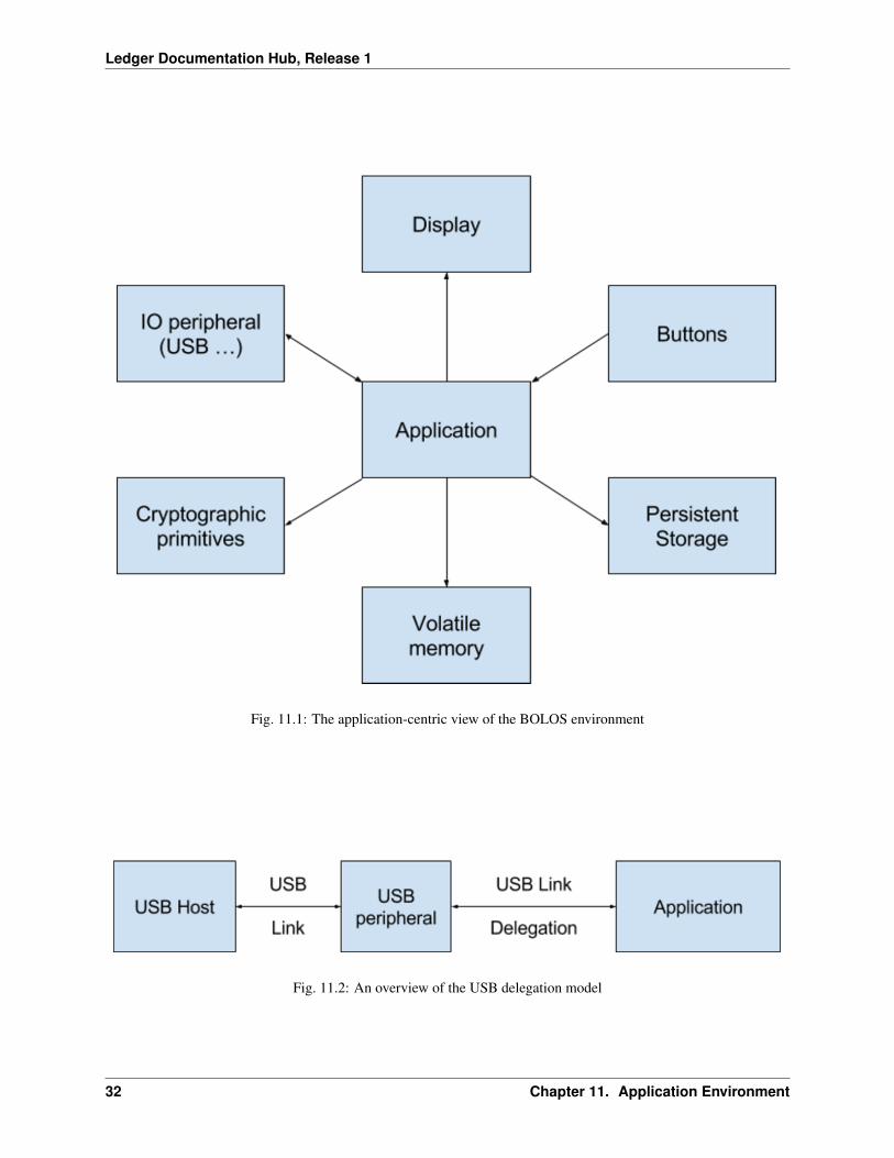
The above diagram shows a view of the system as seen by the application. The app directly accesses multiple pe-ripherals and is the real brain of the device while it is running. Each box can be seen as a coprocessor, under directcommand of the application.
Some peripherals not only receive commands from the SE, but also trigger events which are relayed back to the SE bythe MCU. This is the case for buttons, activated upon user actions, and I/O peripherals which can perform backgroundcommunication (for example, the USB controller) or convey requests to be processed by the application.
In this model, the application is at the center, and does not rely on any other embedded co-applications.
Delegation Model
Once BOLOS boots the application, BOLOS is not reachable anymore, it only provides basic services to the applica-tion during its execution via system calls. As a consequence, BOLOS does not process commands sent to the devicefrom peripherals (like USB) and therefore BOLOS does not play a role in I/O handling.
Featuring these two key points, applications are in charge on the device. This allows them to customize not only thedisplay, but user input actions, and by extension, the way the device is enumerated on USB. If an application requiresMass Storage emulation, or being seen as a WinUSB peripheral, it’s only a matter of event handling.
31
Ledger Documentation Hub, Release 1
Fig. 11.1: The application-centric view of the BOLOS environment
Fig. 11.2: An overview of the USB delegation model
32 Chapter 11. Application Environment

CHAPTER 12
Introduction
In this chapter we will provide a general tutorial for getting your BOLOS development environment set up, followed bysome detailed explanations of the various components of the BOLOS SDKs and what userspace development entails.It is assumed that you have already read the BOLOS Platform chapter and are somewhat familiar with the BOLOSarchitecture.
33

Ledger Documentation Hub, Release 1
34 Chapter 12. Introduction
CHAPTER 13
Getting Started
Developing and / or compiling BOLOS applications requires the SDK matching the appropriate device (the Nano SSDK or the Blue SDK) as well as the following two compilers:
• A standard ARM gcc to build the non-secure (STM32) firmware and link the secure (ST31) applications
• A standard ARM clang above 4.0.0 with ROPI support to build the secure (ST31) applications
Setting up the Toolchain
The Makefiles used by our BOLOS applications look for the gcc and clang installations using the following process:
1. If the BOLOS_ENV environment variable is set, then gcc is used from $BOLOS_ENV/gcc-arm-none-eabi-5_3-2016q1/bin/ and clang is used from $BOLOS_ENV/clang-arm-fropi/bin/.
2. As a fallback, if BOLOS_ENV is not set, then gcc is used from GCCPATH and clang is used from CLANGPATH.
3. As a fallback, if either GCCPATH or CLANGPATH is not set, then gcc and clang, respectively, are used from thePATH.
This allows you to setup both gcc and clang under the same directory and reference it using BOLOS_ENV, or configurewhere each compiler is looked for individually. If your system already has an appropriate version of clang installed,you may simply leave BOLOS_ENV and CLANGPATH unset and clang will be used from the PATH (but make sure toset GCCPATH).
If you’re just looking for a one-size-fits-all solution to satisfy your toolchain needs, here are the steps you shouldfollow:
1. Choose a directory for the BOLOS environment (I’ll use ~/bolos-devenv/) and link the environment vari-able BOLOS_ENV to this directory.
2. Download a prebuilt gcc from https://launchpad.net/gcc-arm-embedded/+milestone/5-2016-q1-update andunpack it into ~/bolos-devenv/. Make sure there is a directory named bin directly inside ~/bolos-devenv/gcc-arm-none-eabi-5_3-2016q1/.
35

Ledger Documentation Hub, Release 1
3. Download a prebuilt clang from http://releases.llvm.org/download.html#4.0.0 and unpack it into~/bolos-devenv/. Rename the directory that was inside the archive you downloaded toclang-arm-fropi, or create a link to the directory with that name. Make sure there is a directorynamed bin directly inside ~/bolos-devenv/clang-arm-fropi/.
Note: Not all of the Makefiles for our applications available on GitHub may recognize BOLOS_ENV in the waydescribed above. If the Makefile is having trouble finding the right compilers, try setting GCCPATH and CLANGPATHexplicitly.
Setting up the SDK
Now that you have your toolchain set up, you need to download / clone the SDK for the appropriate Ledger deviceyou’re working with. You can do this anywhere, it doesn’t have to be in your BOLOS_ENV directory (if you even haveone). Make sure you checkout the tag matching your firmware version.
Ledger Nano S SDK: https://github.com/LedgerHQ/nanos-secure-sdk
Ledger Blue SDK: https://github.com/LedgerHQ/blue-secure-sdk
Finally, link the environment variable BOLOS_SDK to the SDK you downloaded. When using the Makefile for ourBOLOS apps, the Makefile will use the contents of the SDK to determine your target device ID (Ledger Nano S orLedger Blue). Even if you aren’t building an app, loading an app with the Makefile still requires you to have the SDKfor the appropriate device linked to by BOLOS_SDK.
Python Loader
If you intend to communicate with an actual Ledger device from a host computer at all, you will need the Pythonloader installed. For more information on installing and using the Python loader, see BOLOS Python Loader. TheMakefiles for most of our apps interface with the Python loader directly, so if you only need to load / delete apps thenyou don’t need to know how to use the various scripts provided by the Python loader, but you’ll still need it installed.
Building and Loading Apps
In this section, we’ll walk you through compiling and loading your first BOLOS app onto your device. Applicationsthat support multiple BOLOS devices are typically contained within a single repository, so you can use the samerepository to build an app for different Ledger devices. Just make sure that you’ve set BOLOS_SDK to the appropriateSDK for the device you’re using. The Makefiles used by our apps use the contents of the SDK to determine whichdevice you’re using.
Firstly, download the app and make sure to checkout a version of the application that is compatible with your SDKversion. (We’ll do our best to keep the sample apps updated to the latest SDK version.)
git clone https://github.com/LedgerHQ/blue-sample-apps.git
Now you can let the Makefile do all the work. The load target will build the app if necessary and load it onto yourdevice over USB.
cd blue-sample-apps/blue-app-helloworld/make load
36 Chapter 13. Getting Started
Ledger Documentation Hub, Release 1
And you’re done! After confirming the installation on your device, you should see an app named “Hello World”. Theapp can be deleted like so:
make delete
13.4. Building and Loading Apps 37

Ledger Documentation Hub, Release 1
38 Chapter 13. Getting Started

CHAPTER 14
Interaction Between BOLOS and Apps
Since BOLOS is designed based on a single-task model where only a single app runs at any given time, an applicationis independently responsible for a lot of the things a typical OS would do. These things include managing hardwarelike the device screen, buttons, timer, etc. as well as handling all I/O with peripherals. However, there are manyinstances where a BOLOS application has to request the operating system to perform a certain operation. This is doneusing a syscall.
When an application performs a syscall, the Secure Element switches to Supervisor mode and the OS performs therequested task before returning control back to the application, in User mode. All syscalls have a wrapper functionin the SDK that can be used to invoke them. A syscall may be used to access hardware accelerated cryptographicprimitives (most of these functions are defined in include/cx.h in the SDKs), to perform low-level I/O operations(like receiving / transmitting to the MCU), or to access cryptographic secrets managed by BOLOS (for example, toderive a node from the BIP 32 master node).
Error Model
If you are familiar with C programming, you will be used to error codes as the default error model. However, whenprogramming in the embedded world, this traditional model reaches its limits, and can quickly overcomplicate largecodebases. Therefore, we’ve implemented a try / catch system that supports nesting (direct or transitive) using thesetjmp and longjmp API to facilitate writing robust code.
Here is an example of a typical try / catch / finally construct:
BEGIN_TRY {TRY {
// Perform some operation that may throw an error using THROW(...)} CATCH_OTHER(e) {
// Handle error} FINALLY {
// Always executed before continuing control flow}
} END_TRY;
39

Ledger Documentation Hub, Release 1
However there is a single constraint to be aware of with our try / catch system: a TRY clause must always be closedin the appropriate way. This means that if using a return, break, continue or goto statement that jumps out of the TRYclause you MUST manually close it, or it could lead to a crash of the application in a later THROW. A TRY clause canbe manually closed using CLOSE_TRY. Using CLOSE_TRY is only necessary when jumping out of a TRY clause,jumping out of a CATCH or FINALLY clause is allowed (but still, be careful you’re not in a CATCH nested in a TRY).
You should use the error codes defined in the SDKs wherever possible (see EXCEPTION, INVALID_PARAMETER,etc. in os.h). If you decide to use custom error codes, never use an error code of 0.
Developers should avoid creating a new try context wherever possible in order to reduce code size and stack usage.Preferably, an application should only have a single top-level try context at the application entry point (in main()).
Syscall Requirements
BOLOS is based on an exception model for error reporting, therefore, it expects the application to call the BOLOSAPI using this mechanism. If an API function is called from outside a TRY context, then the BOLOS call is denied.
Here is a valid way to call a system entry point:
BEGIN_TRY {TRY {
cx_hash_sha512(...);} FINALLY {}
} END_TRY;
However, as mentioned above, it is preferred to use as few try contexts as possible (not one per syscall). A single,top-level try context can be used to catch any exception thrown by any syscall performed by the application.
40 Chapter 14. Interaction Between BOLOS and Apps
CHAPTER 15
Application Structure and I/O
Many of the existing BOLOS applications are based on a smartcard architecture. This is because BOLOS applicationsare not meant to run standalone, but rather assist a host process (on a computer / smartphone) to perform a secure task(signing a message, encryption / decryption, etc.). Therefore the device is commonly addressed using a command /response scheme. Numerous design decisions have been made when developing the SDKs in order to support thismodel.
However, the Event / Commands / Status model is designed to avoid limitations on the application, as it does notfollow the command / response synchronous model. Developers are free to work around the model and redesign acustom event processing loop to suit their needs.
APDU Interpretation Loop
The command / response scheme used to address the device is similar to the ISO/IEC 7816-4 smartcard protocol. Eachcommand / response packet is called an APDU. The application is driven by a never-ending APDU interpretation loopcalled straight from the application main function.
Each cycle of the APDU interpretation loop calls io_exchange(...) from the SDK, which first sends a responseAPDU (unless it’s the first call, in which case it sends nothing), and then receives the next command APDU.
However, sometimes, a user confirmation to perform a security action must be performed before replying to an APDU(for example, when signing a message). Such behavior is handled by replying no data to the command in the APDUinterpreter by using the IO_REPLY_ASYNCH flag, then following the user action calling io_exchange with theIO_RETURN_AFTER_TX flag and with the amount of data to reply to the stalled command.
For an example of this feature, refer to blue-app-samplesign. In this app, when the command APDU to sign a messageis received (line 510), the flag IO_ASYNCH_REPLY is set and no response APDU is sent. If the user approves theaction, then the button push handler calls io_seproxyhal_touch_approve(...) which sends the responseAPDU using another call to io_exchange(...) with the IO_RETURN_AFTER_TX flag set (line 434). The sameoccurs if the user denies the action, in which case io_seproxyhal_touch_deny(...) is triggered.
41

Ledger Documentation Hub, Release 1
Protocols
It’s important to understand that the APDU protocol used by most BOLOS applications is not implemented by BOLOSitself. Instead, the APDU interpretation is performed entirely by the SDK. This means that applications can choose toimplement another protocol on top of the transport layer (USB HID, USB CCID, BLE, ...) instead of APDU. In fact,the same is true for the transport layer protocols. Applications can customize the way the application is enumerated asa USB device by the host.
Fig. 15.1: Common protocols across BOLOS applications
Unprocessed Events
APDU processing relies on the BOLOS way of framing / transporting APDU packets. All event processing relatedto transfer operations (including USB) is performed within io_exchange(...). Not considering customizationof the transport, some Events are not automagically processed by io_exchange(...) (for example: Button PushEvents, Display Processed Events, Ticker Events, ...). In order to handle these events that cannot be handled automag-ically, io_exchange(...) calls io_event(...) which is defined by the application (not by the SDK).
Developers must take great care in the way they process Events. Events might occur in the middle of APDU transport(most likely Button Push or Ticker Events). As such, io_event(...) must return 1 if events are expected, other-wise the current APDU transport will be terminated (this feature could be used to implement a timeout, for example).
Thanks to a hardware buffer in the SE, it is impossible to miss an Event packet. And, due to the E/Cs/S protocoldesign, no Event will be sent by the MCU until a new Status is sent by the application.
42 Chapter 15. Application Structure and I/O
CHAPTER 16
Display Management
The BOLOS SDKs contain a toolkit for building GUIs called the BOLOS Application Graphics Library (BAGL).BAGL defines a few useful types, most notably bagl_element_t. This type defines a single display element, suchas a rectangle, a line of text, a touchable button (in the case of the Ledger Blue), et cetera. Therefore, an entire GUIconsists of an entire array of such elements. As the device hardware, including the screen, is managed by the MCU,the BAGL elements need to be transported to the MCU over SEPROXYHAL in order to display them. This is doneusing a Display Status.
A Display Status may be used to send a single BAGL element to the MCU. However, due to the design of the E/Cs/Sprotocol, in order to send a sequence of BAGL elements the application must asynchronously send Display Statusesand wait for Display Processed Events before sending the next one, as well as handling the other Events that arereceived from the MCU in the mean time. As this is something that must be done by every BOLOS application, a setof utilities have been defined in the SDK to facilitate this process. These utilities also simplify the process of handlinguser input events, such as button presses.
Asynchronous Display and Interaction Helpers
To facilitate the process of implementing an asynchronous display manager loop, a set of macros have been defined inthe BOLOS SDKs. All these macros have the prefix UX_, and use a global variable of type ux_state_t called uxto maintain the user interface state.
UX_INIT(...) This macro is to be called when initializing the application, prior to sending the first Display Status.
UX_DISPLAY(...) This macro takes an array of BAGL elements to be displayed and renders them, asyn-chronously. It is to be called when a new screen is to be displayed over the current one. This macro onlysends the first element of the given array using a Display Status. Therefore, further Commands and Statuses areprohibited until the Display Processed Event is sent by the MCU.
UX_REDISPLAY() This macro restarts the process of drawing the current screen. It behaves like UX_DISPLAY(...), but takes no arguments.
UX_DISPLAYED() This macro returns 0 when the array requested to be displayed by UX_DISPLAY(...) orUX_REDISPLAY() has not been displayed entirely, or a non-zero value when it has.
43

Ledger Documentation Hub, Release 1
UX_DISPLAYED_EVENT(...) This macro is to be called to handle Display Processed Events (generally in theio_event(...) function). It displays the next element in the array given as a parameter to UX_DISPLAY(...). This macro sends a Display Status if an element remains to be displayed in the given array. Therefore,further Commands and Statuses are prohibited until the Display Processed Event is sent by the MCU.
UX_BUTTON_PUSH_EVENT(...) This macro facilitates handling of Button Push Events, by setting the buttonreleased flag and calling the button handler implicitly passed to UX_DISPLAY(...).
See the sample apps for examples of how to use these macros. The main concept to remember is that after a DisplayStatus has been sent, the application must wait, asynchronously, for the Display Processed Event before being able tocontinue to display more elements of the GUI.
BOLOS UX
The BOLOS UX is the implementation of the device-wide user interface; it is a component of the dashboard. Applica-tions delegate certain jobs to the BOLOS UX in order to retain consistency across all apps for certain UI components(like the status bar on the Ledger Blue), as well as to allow the operating system to override the application’s UI whennecessary (for example, when locking the screen). The application interfaces with the BOLOS UX using os_ux(...), which is a syscall. However, applications don’t need to call this function directly as it is automatically called bythe display interaction helpers (the UX_ macros).
Applications should delegate Events like Button Push Events to the BOLOS UX (in this case, usingUX_BUTTON_PUSH_EVENT(...)) instead of handling them directly in case the BOLOS UX needs to overridethe application’s UI. If the event is consumed by the BOLOS UX (for example, a button press while the user isunlocking the screen) then the event is not passed on to the application.
44 Chapter 16. Display Management
CHAPTER 17
Persistent Storage and PIC
BOLOS applications have access to two different types of memory in the Secure Element: a small amount of RAMfor the call stack and certain global variables, and a considerably larger amount of flash memory for persistent stor-age. Access to flash memory is regulated by the Memory Protection Unit which is configured by BOLOS to preventapplications from tampering with parts of flash memory that they shouldn’t. However, applications are able to accessthe part of flash memory where their constant data and code is defined. This data includes code and const variables,but applications may also allocate extra space in NVRAM to be used at runtime for persistent storage.
Types of Memory
All global variables that are declared as const are stored in read-only flash memory, right next to code. All normalglobal variables that are declared as non-const are stored in RAM. However, thanks to the link script (script.ld) in the SDK, global variables that are declared as non-const and are given the prefix N_ are placed in a specialwrite-permitted location of NVRAM. This data can be read in the same way that regular global variables are read.However, writing to NVRAM variables must be done using the nvm_write(...) function defined by the SDK,which performs a syscall. When loading the app, NVRAM variables are initialized with data specified in the app’s hexfile (this is usually just zero bytes).
Warning: Initializers of global non-const variables (including NVRAM variables) are ignored. As such, thisdata must be initialized by application code.
Flash Memory Endurance
The flash memory for the ST31G480, which is the Secure Element used in the Ledger Blue, is rated for 500 000 erase/ write cycles. This should be more than enough to last the expected lifetime of the device, but only if applications useit properly. Applications should avoid erasures as much as possible. Here are some techniques for avoiding wearingout the device’s flash memory.
45

Ledger Documentation Hub, Release 1
Firstly, if you intend to be changing data in flash memory many times while an application is running, consider cachingthe data in RAM and then flushing to flash memory when the application has finished its operation. This of course hasthe downside of possible data loss if the user powers off the device (perhaps by unplugging it, in the case of the NanoS) before the data has been written to persistent storage. Secondly, developers should be aware that flash memorypages are aligned to 64-byte boundaries. The rating of 500 000 erase / write cycles mentioned earlier means that eachpage in flash memory is expected to survive 500 000 erasures. As such, one can develop an application that writes toas few pages as possible. For example, if you intend to store 32 bytes of data in flash memory, write amplification canbe avoided by making sure that 32 bytes of data is contained entirely within a single page (and modified using only asingle call to nvm_write(...)). If the data crossed a 64-byte page boundary, then writing to it once may requiretwo pages to be erased instead of just one.
In the future, Ledger will provide various persistent storage utilities within BOLOS and the SDKs to simplify theprocess of using flash memory efficiently.
PIC and Model Implications
PIC stands for Placement Independent Code. The BOLOS toolchain produces PIC to allow for the code Link addressto be different from the code Execution address. For example, the main function is linked in the generated applicationat address 0xC0D00000. However, the slot used when loaded into the Secure Element could be 0x10E40400.Therefore, if the code makes a reference to 0xC0D00000, even with an offset, it would be denied access as theapplication is locked by the Memory Protection Unit (not to mention, this is not the correct address of the mainfunction at runtime).
The PIC assembly generator makes sure every dereference is relative to the Program Counter, and never to an arbitraryaddress resolved during the link stage. This behavior is supported by clang versions 4.0.0 and later.
Traditionally, PIC code implies the BSS segment (RAM variables) is at a constant offset of the code. For example, ifcode is at 0xC0D00000, then global vars may be at 0xC2D00000, so if loaded at 0x10E00000 then global varswould be at 0x12E00000. However, BOLOS uses a fixed address for global vars. The global variables start addressand length are defined in the link script. Only the code is meant to be placed at different addresses (in flash memory,rather than RAM).
The model we chose has limitations, which are related to the way const data and code is referenced in other constdata. Here is a simple example:
const char array1[] = {1, 2, 3, 4};const char array2[] = {1, 2, 3, 4};const char *array_2d[] = {array1, array2};
void main() {int sum, i, j;sum = 0;for (i = 0; i < 2; i++) {
for (j = 0; j < 4; j++) {sum += array_2d[i][j]; // Core Fault!
}}
}
In the example above, when dereferencing array_2d, the compiler uses a link-time address (in the 0xC0D00000space, following the previous examples). This is not where the program is loaded in memory at runtime. Therefore,when the dereference is executed, it causes a Core Fault that effectively stalls the SE. Luckily, the solution is prettysimple, thanks to a small piece of assembly provided with the SDKs which is invoked with the PIC(...) macro.PIC(...) uses the current load address to adjust the link-time address in order to acquire the correct runtime ad-dress of const data and code. The above examples can be corrected by modifying the line where array_2d isdereferenced to do the following:
46 Chapter 17. Persistent Storage and PIC

Ledger Documentation Hub, Release 1
sum += ((const char*) PIC(array_2d[i]))[j];
The same mechanism must be applied when storing function pointers in const data. The PIC call cast is just different.Additionally, if a non-link-time address is passed to PIC(...), then it will be preserved. This is possible due to thewisely chosen link-time address which is beyond both real RAM and loadable addresses. For example, PIC(...) isused during a call to io_seproxyhal_display_default(...), all display elements can hold a reference to astring to be displayed with the element, and the string could be in RAM or code, and therefore PIC(...) is appliedto acquire the correct runtime address of the string, even if it’s in RAM.
17.3. PIC and Model Implications 47
Ledger Documentation Hub, Release 1
48 Chapter 17. Persistent Storage and PIC
CHAPTER 18
Common Pitfalls and Troubleshooting
In this section, we’ll walk you through a lot of concepts that are hard to grasp when developing on the BOLOSplatform, and we’ll provide some analysis of common failure scenarios that you might experience while developingapplications.
Not Enough RAM
At the time of writing, the default link script provided by the SDK for the Ledger Nano S allocates 4 KiB of RAM forapplications to use. This 4 KiB has to be enough to store all global non-const and non-NVRAM variables as well asthe call stack (which is currently set to 768 bytes by default, also defined in the link script).
This is the linker error you will experience if you declare too many global non-const and non-NVRAM variables to fitin RAM:
bin/app.elf section `.bss' will not fit in region `SRAM'
The only solution to this problem is, of course, using less RAM. You can accomplish this by making your application’smemory layout more efficient. Alternatively, if you’re feeling adventurous, you can attempt to modify the link script(script.ld in the SDKs) to optimize the space allocated for the call stack. If you choose to pursue the latter option,we recommend you read the next section as well.
Stack Overflows
Determining the exact amount of the call stack used by your application can be difficult to do without simply runningyour application. The technique we recommend for avoiding stack overflows is using a stack canary. Creating a stackcanary involves setting a magic value at the start of the stack area (the stack grows towards lower addresses, so acanary at the start of this region will be located at the top of the stack), and then the canary is checked regularly. If thecanary was modified, then this means there was a stack overflow.
In a future version of the BOLOS SDKs, this feature will be implemented automatically. Until then, this is therecommended way to implement a stack canary:
49

Ledger Documentation Hub, Release 1
// This symbol is defined by the link script to be at the start of the stack// area.extern unsigned long _stack;
#define STACK_CANARY (*((volatile uint32_t*) &_stack))
void init_canary() {STACK_CANARY = 0xDEADBEEF;
}
void check_canary() {if (STACK_CANARY != 0xDEADBEEF)
THROW(EXCEPTION_OVERFLOW);}
The canary should be checked regularly. For example, you could run the check every time io_event(...) iscalled.
Error Handling
Error handling in C can sometimes be a bit counter-intuitive. With our error model, there are two common failurescenarios.
Firstly, you must take care to always close a try context when jumping out of it. For example, in the block of codebelow, the CLOSE_TRY macro must be used to close the try context before returning from the function in the casethat i > 0. However, in the CATCH clause, the try has already been closed automatically so CLOSE_TRY is notnecessary.
bool is_positive(int8_t i) {BEGIN_TRY {
TRY {if (i == 0)
THROW(EXCEPTION);if (i > 0) {
CLOSE_TRY;return true;
}} CATCH_OTHER(e) {
return false;} FINALLY {}
} END_TRY;return false;
}
Another common failure scenario is caused by the compiler making invalid assumptions when optimizing your codebecause it doesn’t understand how our exception model works. To avoid this problem, when modifying variableswithin a try / catch / finally context, always declare those variables volatile.
uint16_t multiply(uint8_t a, uint8_t b) {volatile uint16_t product = 0;volatile uint8_t multiplier = b;while (true) {
BEGIN_TRY {TRY {
if (multiplier == 0)
50 Chapter 18. Common Pitfalls and Troubleshooting
Ledger Documentation Hub, Release 1
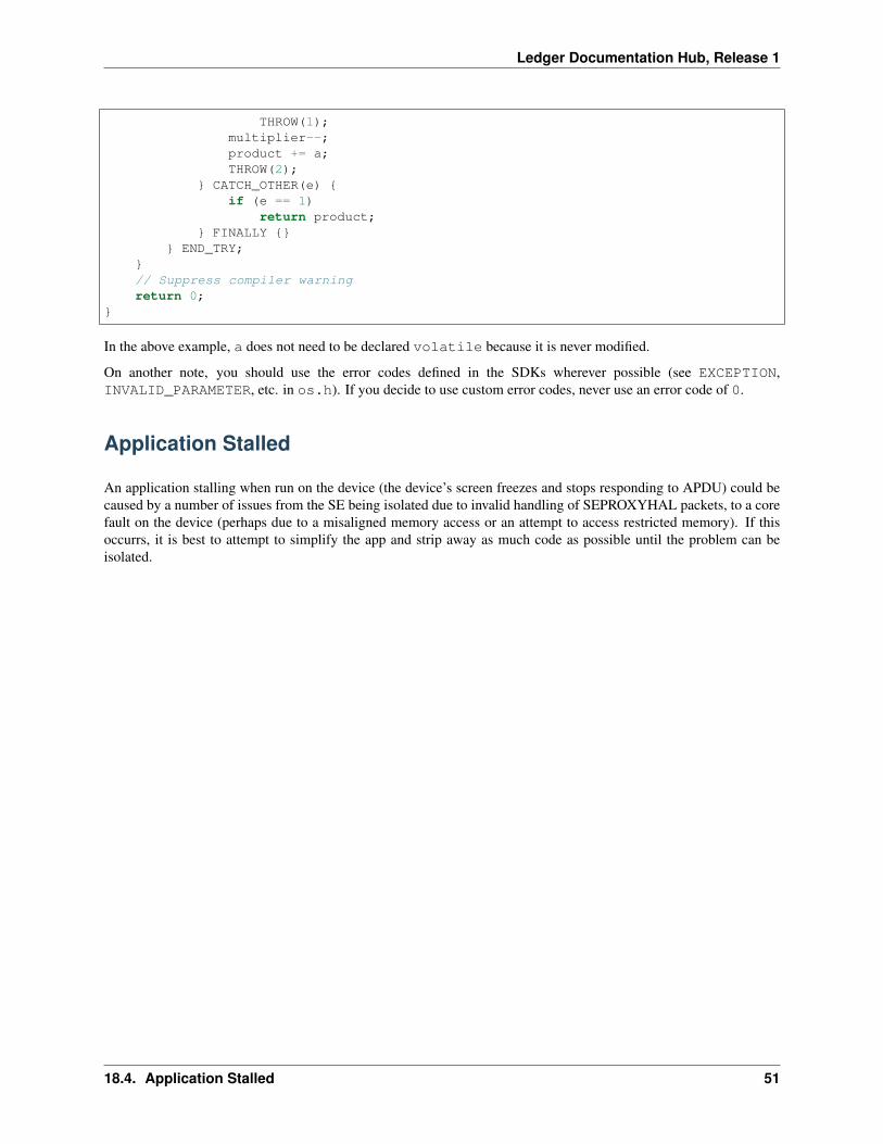
THROW(1);multiplier--;product += a;THROW(2);
} CATCH_OTHER(e) {if (e == 1)
return product;} FINALLY {}
} END_TRY;}// Suppress compiler warningreturn 0;
}
In the above example, a does not need to be declared volatile because it is never modified.
On another note, you should use the error codes defined in the SDKs wherever possible (see EXCEPTION,INVALID_PARAMETER, etc. in os.h). If you decide to use custom error codes, never use an error code of 0.
Application Stalled
An application stalling when run on the device (the device’s screen freezes and stops responding to APDU) could becaused by a number of issues from the SE being isolated due to invalid handling of SEPROXYHAL packets, to a corefault on the device (perhaps due to a misaligned memory access or an attempt to access restricted memory). If thisoccurrs, it is best to attempt to simplify the app and strip away as much code as possible until the problem can beisolated.
18.4. Application Stalled 51

Ledger Documentation Hub, Release 1
52 Chapter 18. Common Pitfalls and Troubleshooting

CHAPTER 19
External Documentation
In addition to the documentation provided in this hub, we also have the following resources available:
• BOLOS Python Loader
53

Ledger Documentation Hub, Release 1
54 Chapter 19. External Documentation
Index
CCustom CA, 26Custom CA Certificate, 26
DDevice, 26Device Certificate, 26
IIssuer, 26Issuer Certificate, 26
OOwner, 26Owner Certificate, 26
55