lecture t06: high performance bearing comparison
TRANSCRIPT

Copyright© 2015 by Turbomachinery Laboratory, Texas A&M Engineering Experiment Station
HIGH PERFORMANCE BEARING COMPARISON
Bernard Quoix Head of Rotating Machinery Department
TOTAL E&P
64000 Pau, France
Thomas Shoup
Engineering Manager, Lufkin-RMT
Lufkin Industries, LLC
Wellsville, NY, USA
Josh Ronan, P.E.
Design Engineer
Lufkin Industries, LLC
Lufkin, TX, USA
Alain Gelin
Senior Rotating Equipment
TOTAL E&P
64000 Pau, France
Chad Robertson, P.E.
Project Engineer
Lufkin Industries, LLC
Lufkin, TX, USA
Gwenael Perney
Technical Manager, Lufkin France
Lufkin Industries, LLC
Fougerolles, France
Bernard Quoix is Head of Total E&P
Rotating Machinery Department since
November 2003. He started his career in
1979 within Total Operations in the North
Sea, in charge of the MCP01
turbocompressors project, then from 1986 to
1989 joined Turbomeca Industrial Division
as Head of Engineering, then went to
Renault Car Manufacturer as Assistant
Manager of the engines testing facilities, before joining Elf
Aquitaine and eventually TOTAL, mainly involved in all aspects
of turbomachines for new oil and gas field development,
commissioning and start-up, bringing his expertise to TOTAL’s
Operations worldwide.
Bernard Quoix graduated from ENSEM (Ecole Nationale
Supérieure d'Electricité et de Mécanique) in 1978 and then
completed his engineering education at ENSPM (Ecole
Nationale du Pétrole et des Moteurs) in Paris, specializing in
Internal Combustion Engines.
He is a member of the Turbomachinery Advisory Committee
from Texas A&M in Houston, since 2005, President of
European Turbine Network (ETN) since 2010, and Vice
president of Assosication Française de Mécanique (AFM),
based in Paris, since 2013.
Dr. Alain Gelin is a Senior Rotating
Equipment Engineer at TOTAL E&P Head
Quarters in Pau, France. He is involved in
the development schemes for compression,
pumping and power generation systems and
he supports Projects and site trouble
shooting activities as well. He is also deeply
involved in qualification programs for new
equipment and his expertise covers all
mechanical aspects such as rotordynamics, aerodynamics,
lubrication, magnetic bearings, stress and modal analysis, LNG
compressors, testing… He joined TOTAL in 2005, and
previously is worked 20 years for GE Oil&Gas (former
Thermdoyn) where is was successively R&D Mechanical
Engineer and Testing Department Manager for both Steam
Turbine and Centrifugal Compressor applications. He has
authored 10+ technical papers in dynamics and he is member
of the IFToMM committee. Dr. Gelin obtained his Ph.D. and
Master’s Degree at INSA Lyon.
Thomas P. Shoup is the Engineering
Manager at Lufkin Industries, LLC part of
GE Oil and Gas in Wellsville, NY. He has
worked in the rotating machinery industry
for 28 years in rotordynamics and bearing
design. Before Lufkin, he worked for
Dresser-Rand, Sverdrup Technology, Inc.,
and Siemens Demag Delaval
Turbomachinery, Inc. He holds a B.S.
degree in Engineering Science and Mechanics and a M.S.
degree in Mechanical Engineering. Mr. Shoup is a member of
ASME.

Copyright© 2015 by Turbomachinery Laboratory, Texas A&M Engineering Experiment Station
Chad Robertson, P.E. is a Project
Engineer at Lufkin Industries, LLC part of
GE Oil and Gas in Lufkin, TX. He has
worked with Lufkin for 10 years and is
currently directing the technology and
development efforts for the Power
Transmission Division. He has significant
experience in gear design and
manufacturing. He holds a B.S degree in
Mechanical Engineering from Texas A&M University. Mr.
Robertson is an active member on the Sound and Vibration
Committee for the American Gear Manufacturers Association,
AGMA.
Josh Ronan, P.E. is a Design Engineer at
Lufkin Industries, LLC part of GE Oil and
Gas in Lufkin, TX. He joined Lufkin in
2008, and is now part of the Technology
and Development Department in the Power
Transmission Division. He has designed
High Speed and Low Speed gearboxes and
the last 3 years worked on R&D projects.
Mr. Ronan obtained a B.S. degree in
Mechanical Engineering from the University of Texas at Tyler.
Gwenaël Perney is currently Technical
Manager at Lufkin Industries, LLC part of
Ge Oil and Gas in Fougerolles, France.
He joined LUFKIN France in 2002, and
he’s now specialized in High Speed gears
and is deeply involved in troubleshooting
for all gears issues, including vibration
and temperatures problems. His
responsibility includes also product
development and therefore is involved in all R&D programs.
Mr. Perney received a degree in Engineering Design and
Mechanics from the Ecole Polytechnique Universitaire de Lille
Politech’Lille.
ABSTRACT
With the increasing demand for high performance
gearboxes, larger, faster, more highly loaded bearings are
requiring more oil and creating more heat than ever before.
This means the lubrication systems must be larger to handle the
increasing heat loads and oil demands. Offshore applications, in
particular, are greatly affected due to space constraints and
increased lubrication system size and cost. In an effort to
reduce the oil flow and heat load requirements for the gearbox,
experimental tests and field tests were performed with three
different bearing designs. The designs were pressure dam,
offset half, and tilting pad journal bearings. Data was acquired
using a dedicated test rig that allows operation at and beyond
design speeds and loads. Field test data was also collected from
a full speed, full load string test of a turbo compressor
drivetrain. This paper will present results of the experimental
test data from these three bearings to assist in the selection of a
design that will provide optimum performance for given
operation conditions.
INTRODUCTION
The extraction, refining, and processing of oil and gas
requires a variety of turbomachinery equipment, such as
compressors, expanders, and generators. Much of this
equipment relies on gearboxes to function at optimum speeds.
Turbomachinery gearboxes are generally considered to be
relatively efficient equipment; typically achieving measured
efficiency values greater than 98 percent. Even at these
efficiency levels, gearboxes in turbo-equipment strings, which
commonly operate at or above 55,000 hp (40 MW), can have
considerable losses. The losses on these units are comparable to
the amount of power created by the engines of the world’s
fastest supercars.
The power consumed by the gearboxes is from mechanical
shearing of oil and aerodynamic windage from gears, bearings
and couplings. A large portion of the losses come from the
bearings. Most of the lost power is converted into heat energy
and dissipated with circulating oil. In order to absorb this heat,
lubrication systems must be sized accordingly. Lubrication
systems can often be an expensive and real estate intensive
subsystem for turbomachines. Therefore low power losses and
oil flows are very desirable traits for gearboxes. In an effort to
make improvements in these areas, a variety of bearing designs
needed to be tested for use in geared turbomachinery
applications.
Significant work on research, testing, and analysis has been
dedicated to studying rotordynamics and stability of journal
bearing designs which will only be covered at a very high level
in this paper. This paper will instead focus on a direct
comparison of three competing bearing designs in the same
gearbox application, with special interest given to oil
consumption and power loss. The following is a brief overview
and description of the bearing designs chosen for this test.
BEARING DESIGNS
Hydrodynamic journal bearings are currently the bearings
of choice for most turbomachinery equipment including
gearboxes. They possess several characteristics that are
desirable such as high reliability and good rotordynamic
damping characteristics. Several different designs of journal
bearings are commonly utilized for gearboxes. The designs are
all variations of a sliding bearing where a shaft journal slides on
a thin film of oil. The design variations utilize different
geometries and features in an effort to achieve rotordynamic

Copyright© 2015 by Turbomachinery Laboratory, Texas A&M Engineering Experiment Station
stability and avoid sub-synchronous vibrations. The designs
that were tested were pressure dam, offset halves, and tilting
pad journal (TPJ) bearings.
Pressure Dam bearings are essentially a plain journal
bearing with a pocket cut in one half that has an abrupt stop at
some point in the shell, see Figure 1. Viscous and inertia effects
results in a buildup of pressure at the dam, this localized high
pressure area creates an artificial load on the shaft that helps
stabilize the rotor, Wilcock and Booser (1957).
Figure 1 - Pressure Dam Journal Bearing
Offset half bearings utilize geometry where two bearing
shell pads are not concentric to each other, see Figure 2. This
creates a situation where oil is converged into a wedge helping
stabilize the shaft in the bearing, Allaire and Flack (1981).
Figure 2 - Offset Halves Journal Bearing
Tilting Pad Journal Bearings are comprised of multiple
pads that are supported by pivots, see Figure 3. The pads
support the shaft and pivot independently from each other. The
pads are typically machined at a larger diameter than they are
assembled to create a converging oil film. The tilting pad
design is inherently very stable.
Figure 3 - Tilting Pad Journal Bearing
The three previously mentioned bearing designs are by no
means an exhaustive list of the possible options, but are
common in turbomachinery and tested for this application.
TESTING CONFIGURATION
The dedicated test rig consists of a shaft, a test bearing,
support bearings, a load cell, a hydraulic cylinder, and a
fabricated housing, see Figure 4 and Figure 5. The test bearing
and support bearings have separate oil supplies and drains
which allow for the oil flow to each bearing to be directly
measured and the power loss to be calculated.
Figure 4 - Dedicated Test Rig with Cover Removed
Copyright© 2015 by Turbomachinery Laboratory, Texas A&M Engineering Experiment Station
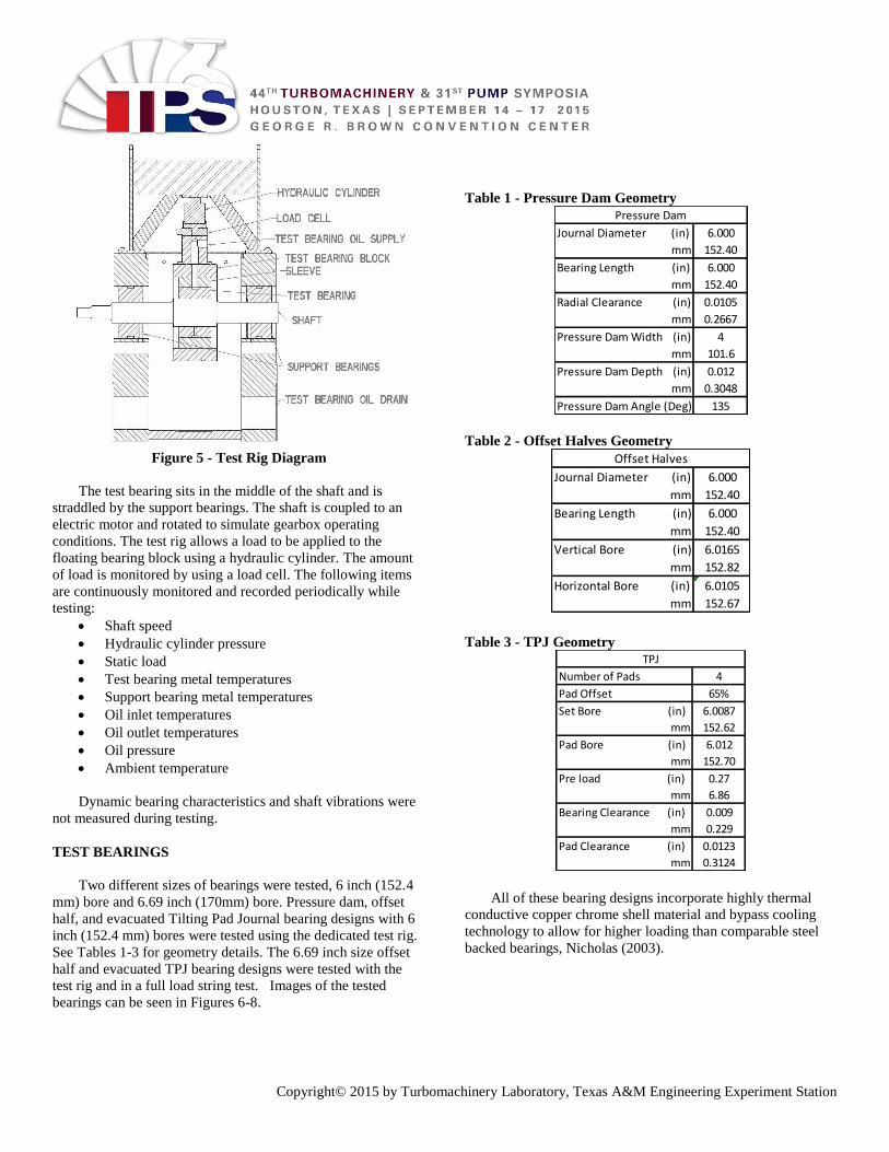
Figure 5 - Test Rig Diagram
The test bearing sits in the middle of the shaft and is
straddled by the support bearings. The shaft is coupled to an
electric motor and rotated to simulate gearbox operating
conditions. The test rig allows a load to be applied to the
floating bearing block using a hydraulic cylinder. The amount
of load is monitored by using a load cell. The following items
are continuously monitored and recorded periodically while
testing:
Shaft speed
Hydraulic cylinder pressure
Static load
Test bearing metal temperatures
Support bearing metal temperatures
Oil inlet temperatures
Oil outlet temperatures
Oil pressure
Ambient temperature
Dynamic bearing characteristics and shaft vibrations were
not measured during testing.
TEST BEARINGS
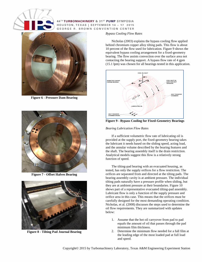
Two different sizes of bearings were tested, 6 inch (152.4
mm) bore and 6.69 inch (170mm) bore. Pressure dam, offset
half, and evacuated Tilting Pad Journal bearing designs with 6
inch (152.4 mm) bores were tested using the dedicated test rig.
See Tables 1-3 for geometry details. The 6.69 inch size offset
half and evacuated TPJ bearing designs were tested with the
test rig and in a full load string test. Images of the tested
bearings can be seen in Figures 6-8.
Table 1 - Pressure Dam Geometry
Table 2 - Offset Halves Geometry
Table 3 - TPJ Geometry
All of these bearing designs incorporate highly thermal
conductive copper chrome shell material and bypass cooling
technology to allow for higher loading than comparable steel
backed bearings, Nicholas (2003).
Journal Diameter (in) 6.000
mm 152.40
Bearing Length (in) 6.000
mm 152.40
Radial Clearance (in) 0.0105
mm 0.2667
Pressure Dam Width (in) 4
mm 101.6
Pressure Dam Depth (in) 0.012
mm 0.3048
Pressure Dam Angle (Deg) 135
Pressure Dam
Journal Diameter (in) 6.000
mm 152.40
Bearing Length (in) 6.000
mm 152.40
Vertical Bore (in) 6.0165
mm 152.82
Horizontal Bore (in) 6.0105
mm 152.67
Offset Halves
Number of Pads 4
Pad Offset 65%
Set Bore (in) 6.0087
mm 152.62
Pad Bore (in) 6.012
mm 152.70
Pre load (in) 0.27
mm 6.86
Bearing Clearance (in) 0.009
mm 0.229
Pad Clearance (in) 0.0123
mm 0.3124
TPJ
Copyright© 2015 by Turbomachinery Laboratory, Texas A&M Engineering Experiment Station
Figure 6 - Pressure Dam Bearing
Figure 7 - Offset Halves Bearing
Figure 8 - Tilting Pad Journal Bearing
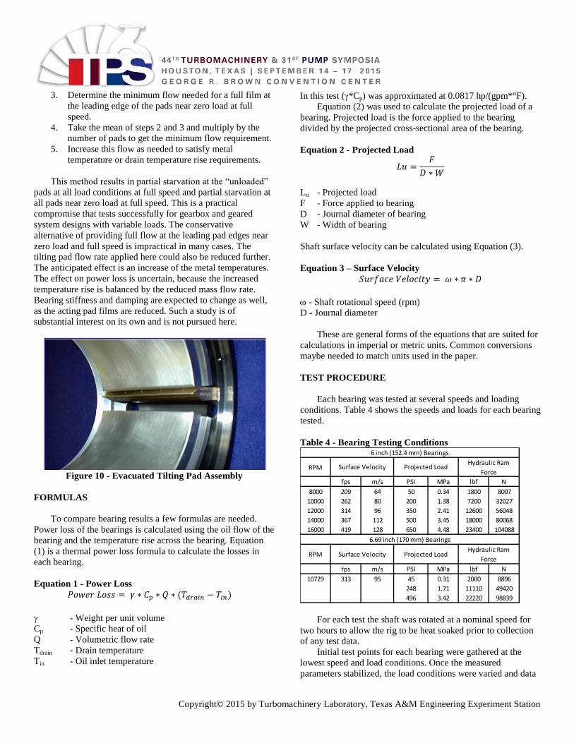
Bypass Cooling Flow Rates
Nicholas (2003) explains the bypass cooling flow applied
behind chromium copper alloy tilting pads. This flow is about
10 percent of the flow used for lubrication. Figure 9 shows the
equivalent bypass cooling arrangement for a fixed-geometry
bearing. The flow assists convection over the surface area not
contacting the bearing support. A bypass flow rate of 4 gpm
(15.1 lpm) was chosen for all bearings tested in this application.
Figure 9 - Bypass Cooling for Fixed-Geometry Bearings
Bearing Lubrication Flow Rates
If a sufficient volumetric flow rate of lubricating oil is
provided at the supply port, the fixed-geometry bearing takes
the lubricant it needs based on the sliding speed, acting load,
and the annular volume described by the bearing features and
the shaft. The bearing assembly itself is the drain restriction.
Analytical models suggest this flow is a relatively strong
function of speed.
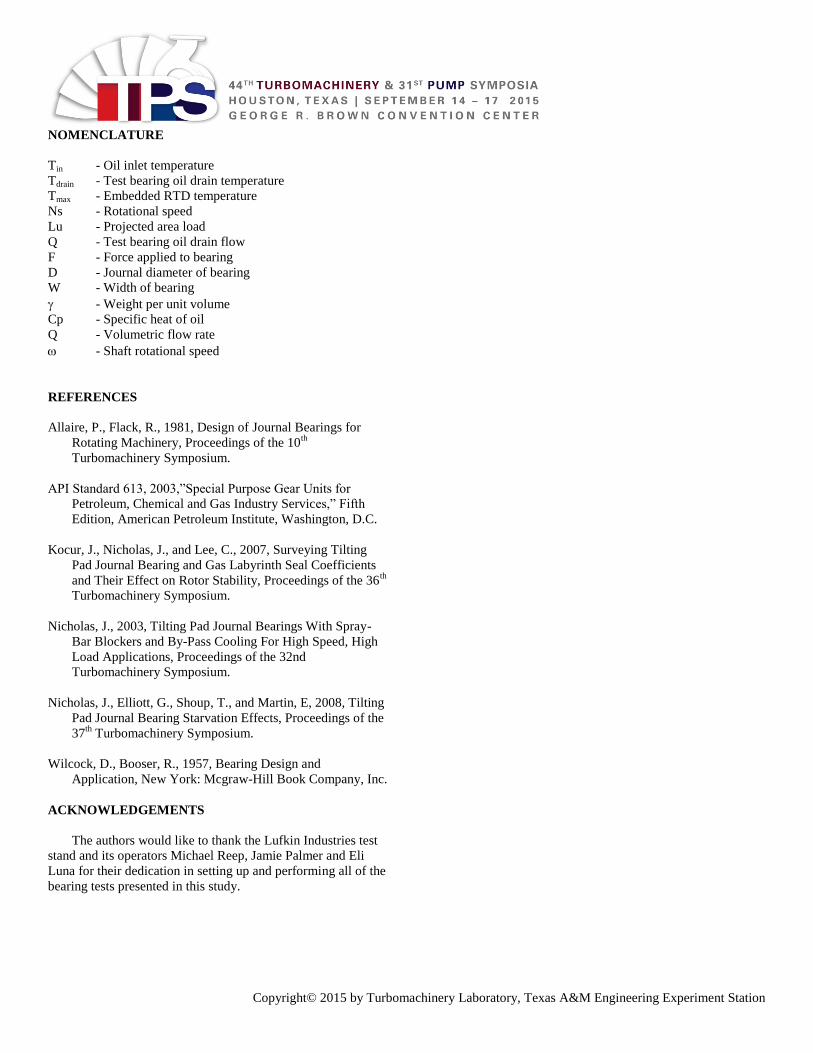
The tilting-pad bearing with an evacuated housing, as
tested, has only the supply orifices for a flow restriction. The
orifices are separated from and directed at the tilting pads. The
bearing assembly cavity is at ambient pressure. The individual
tilting pads naturally have a pressure profile when sliding, but
they are at ambient pressure at their boundaries. Figure 10
shows part of a representative evacuated tilting-pad assembly.
Lubricant flow is only a function of the supply pressure and
orifice area in this case. This means that the orifices must be
carefully designed for the most demanding operating condition.
Nicholas, et al. (2008) discusses the steps used to determine the
oil flow requirements. They are summarized with updates
below:
1. Assume that the hot oil carryover from pad to pad
equals the amount of oil that passes through the pad
minimum film thickness.
2. Determine the minimum flow needed for a full film at
the leading edge of the most loaded pad at full load
and speed.
COOL OIL INLET
LUBRICATING OIL
COOL INLET OIL
USED FOR HEAT
TRANSFER
HEAT TRANSFER
CHAMBER DRAINS
HEAT TRANSFER
CHAMBERS
BABBITTED COPPER
CHROME BEARING
Copyright© 2015 by Turbomachinery Laboratory, Texas A&M Engineering Experiment Station
3. Determine the minimum flow needed for a full film at
the leading edge of the pads near zero load at full
speed.
4. Take the mean of steps 2 and 3 and multiply by the
number of pads to get the minimum flow requirement.
5. Increase this flow as needed to satisfy metal
temperature or drain temperature rise requirements.
This method results in partial starvation at the “unloaded”
pads at all load conditions at full speed and partial starvation at
all pads near zero load at full speed. This is a practical
compromise that tests successfully for gearbox and geared
system designs with variable loads. The conservative
alternative of providing full flow at the leading pad edges near
zero load and full speed is impractical in many cases. The
tilting pad flow rate applied here could also be reduced further.
The anticipated effect is an increase of the metal temperatures.
The effect on power loss is uncertain, because the increased
temperature rise is balanced by the reduced mass flow rate.
Bearing stiffness and damping are expected to change as well,
as the acting pad films are reduced. Such a study is of
substantial interest on its own and is not pursued here.
Figure 10 - Evacuated Tilting Pad Assembly
FORMULAS
To compare bearing results a few formulas are needed.
Power loss of the bearings is calculated using the oil flow of the
bearing and the temperature rise across the bearing. Equation
(1) is a thermal power loss formula to calculate the losses in
each bearing.
Equation 1 - Power Loss
𝑃𝑜𝑤𝑒𝑟 𝐿𝑜𝑠𝑠 = 𝛾 ∗ 𝐶𝑝 ∗ 𝑄 ∗ (𝑇𝑑𝑟𝑎𝑖𝑛 − 𝑇𝑖𝑛)
- Weight per unit volume
Cp - Specific heat of oil
Q - Volumetric flow rate
Tdrain - Drain temperature
Tin - Oil inlet temperature
In this test (*Cp) was approximated at 0.0817 hp/(gpm*°F).
Equation (2) was used to calculate the projected load of a
bearing. Projected load is the force applied to the bearing
divided by the projected cross-sectional area of the bearing.
Equation 2 - Projected Load
𝐿𝑢 =𝐹
𝐷 ∗ 𝑊
Lu - Projected load
F - Force applied to bearing
D - Journal diameter of bearing
W - Width of bearing
Shaft surface velocity can be calculated using Equation (3).
Equation 3 – Surface Velocity
𝑆𝑢𝑟𝑓𝑎𝑐𝑒 𝑉𝑒𝑙𝑜𝑐𝑖𝑡𝑦 = 𝜔 ∗ 𝜋 ∗ 𝐷
- Shaft rotational speed (rpm)
D - Journal diameter
These are general forms of the equations that are suited for
calculations in imperial or metric units. Common conversions
maybe needed to match units used in the paper.
TEST PROCEDURE
Each bearing was tested at several speeds and loading
conditions. Table 4 shows the speeds and loads for each bearing
tested.
Table 4 - Bearing Testing Conditions
For each test the shaft was rotated at a nominal speed for
two hours to allow the rig to be heat soaked prior to collection
of any test data.
Initial test points for each bearing were gathered at the
lowest speed and load conditions. Once the measured
parameters stabilized, the load conditions were varied and data
RPM
fps m/s PSI MPa lbf N
8000 209 64 50 0.34 1800 8007
10000 262 80 200 1.38 7200 32027
12000 314 96 350 2.41 12600 56048
14000 367 112 500 3.45 18000 80068
16000 419 128 650 4.48 23400 104088
RPM
fps m/s PSI MPa lbf N
10729 313 95 45 0.31 2000 8896
248 1.71 11110 49420
496 3.42 22220 98839
Surface Velocity
6 inch (152.4 mm) Bearings
6.69 inch (170 mm) Bearings
Surface Velocity Projected LoadHydraulic Ram
Force
Hydraulic Ram
ForceProjected Load

Copyright© 2015 by Turbomachinery Laboratory, Texas A&M Engineering Experiment Station
points were taken. Each loading condition was measured at the
initial speed. The speed was then increased until all loading
conditions were measured. This process continued until all data
points were recorded or until the test bearing or support
bearings reached 250°F (121°C). The shaft speed reached at
least 14,000 rpm, which equates to a bearing surface velocity of
367 fps (111.9 m/s) and a load of 650 psi (4.48 MPa) for all test
bearings. The maximum speeds and loads surpass typical
operating conditions for hydrodynamic journal bearings in a
gearbox. The 6.69 inch bearings were contract bearings and not
dedicated test bearings and were only tested at 105 percent of
designed operating speed. After all data points were recorded, a
few points were rechecked to insure no significant hysteresis.
ANALYTICAL COMPARISONS FOR 6 INCH
BEARINGS
A commercially available bearing analysis code was used
for comparisons to tested flow, power loss, and maximum
temperature. Multiple codes are not compared to the test data
here. For background on bearing code variations, Kocur, et al.
(2007) discuss the results from multiple codes attempting to
model the same bearing design.
Pressure Dam Model
Figure 11 compares oil flow prediction to tests of the
pressure dam bearing. The analytically predicted oil flow was
very consistent with test data at low speeds, but the results
started diverging at higher shaft speeds. The analytical model
show a notable increase in flow as a function of shaft speed
while the test data oil flows were nearly constant over the tested
speed range. Power loss comparisons are shown in Figure 12
for 50 psi and 650 psi loading. Figure 13 plots temperatures vs.
loading at 8,000 rpm, 12,000 rpm, and 14,000 rpm. Power loss
predictions are slightly lower than tests, while temperature
predictions are consistently higher than tests for speeds below
14,000 rpm. The 6” pressure dam bearing design is not
recommended at 14,000 rpm (366 fps).
Figure 11 - Bearing Oil Flow vs Speed
Figure 12 - Bearing Loss vs Speed 50 and 650 psi Loading
Figure 13 - Metal Temperature vs Loading
Offset Halves Model
Figure 14 compares oil flow prediction to tests of the offset
halves bearing. The increase of flow with speed is again to be
expected for the fixed geometry model. The test data on this
bearing shows the flow has a lower correlation to speed than
the analytical predictions. Power loss comparisons are shown in
Figure 15 for 50 psi and 650 psi loading. Figure 16 plots
temperatures vs. loading at 8,000 rpm, 12,000 rpm, and 16,000
rpm. The model fits the testing up to and including the limit of
16,000 rpm (419 fps).
Figure 14 - Bearing Oil Flow vs Speed

Copyright© 2015 by Turbomachinery Laboratory, Texas A&M Engineering Experiment Station
Figure 15 - Bearing Loss vs Speed50 and 650 psi Loading
Figure 16 - Metal Temperature vs Loading
Tilting Pads Model
Flows for the tilting pads are only dependent on the
restrictions of orifices in this design. Orifice calculations
matched the tested flows here. Power loss comparisons are
shown in Figure 17 for 50 psi and 650 psi loading. Figure 18
plots temperatures vs. loading at 8,000 rpm, 12,000 rpm, and
16,000 rpm. The model shows only partial agreement, as good
temperature predictions throughout most of the test range are
tempered by excessive power losses. Turbulence correction in
the tilting pads model is one major influence on loss and
temperature correlation. The critical Reynolds number is set to
950 in the analytical models. The bearings reach this value by
10,000 rpm for all load cases and by 8,000 rpm for the
maximum loading.
Figure 17 - Bearing Loss vs Speed 50 and 650 psi Loading
Figure 18 - Metal Temperature vs Loading
BEARING DESIGN COMPARISON
The previous results compared the analytical predictions to
the test data for the various bearing designs. Direct
comparisons of bearing test data for each bearing design were
also reviewed.
RESULTS 6 (152.4 MM) INCH BEARINGS
Figure 19 shows the maximum oil flow observed for each
speed of the bearing designs tested. The oil flow for the
pressure dam and offset half bearings is considerably less than
that of the TPJ.

Copyright© 2015 by Turbomachinery Laboratory, Texas A&M Engineering Experiment Station
Figure 19 - Oil Flow of Test Bearings
Over Tested Speed Range
Table 5 shows the power loss of the different bearing
designs at the tested speed and load conditions.
Table 5 - Power Losses of Various Bearing Designs
*** - Data point was not obtained due to support bearing
temperatures.
This table shows that load has a relatively small effect on
the overall power loss of the bearings.
Figure 20 - Bearing Metal Temperature vs Projected Load
Figure 20 shows the bearing metal temperatures at the test
conditions. The results show that as the surface velocity
increases the bearing metal temperature also increases. The TPJ
maintains the coolest bearing temperature of the three designs
with the pressure dam measuring the highest temperatures.
Together, Figures 19 and 20 lead to the reasonable conclusion
that the bearing with the highest lubrication flow rate has the
lowest metal temperature. An interesting comparison was made
by enforcing the offset halves bearing flow rate onto the tilting
pad bearing analytical model. The result was roughly a 4%
increase in metal temperature at 12,000 rpm and an 8% increase
in temperature at 16,000 rpm. This indicates the tilting pad
bearing though starved past 12,000 rpm may still have a
temperature advantage over the offset halves bearing for the
same flow rate. Such a prediction in turn needs to be verified by
testing and may be of limited value when evacuated pad flow
requirements are known. (API 613, 2003) standard allows a
maximum projected load of 500 psi (3.45 MPa). If a reasonable
temperature limit of 212 °F (100 °C) is used the pressure dam
bearing is limited around 12,000 rpm (314 fps), the offset half
14,000 rpm (367 fps), and the TPJ 16,000 rpm (419 fps) based
on this test data.
FULL LOAD STRING TEST DATA
The 6.69 inch (170mm) offset halves and TPJ bearings that
were tested on the dedicated tester were also tested in a full
speed, full load condition string test. One piece of data that can
be extracted from the string test and correlated to the dedicated
test rig results is the metal temperature of the bearings. The
string test condition of 105 percent speed and 100 percent load
yielded temperatures of 206.6°F (97°C) and 204.8°F (96°C) for
the offset halves and TPJ bearings respectively. This correlates
well to the test data collected on the dedicated tester with the
temperatures being 208.4°F (98°C) and 213.8° (101°C) for the
offset halves and TPJ bearings. These minor temperature
discrepancies, less than 9°F (5°C), can be easily accounted for
with variations in manufacturing and testing conditions.
CONCLUSIONS
Efficiency and oil flow are becoming a top priority for high
performance gearboxes. Bearing selection can make a
substantial difference in a gearboxes performance. This study
shows that each bearing design tested has its strengths and
weaknesses. Careful design and selection must be made by the
engineer based on the desires and requirements of the end user.
At lower journal velocities the pressure dam bearing will
require the least oil flow but give the highest bearing
temperature while maintaining a good power loss. The most
demanding operating conditions require a TPJ to handle the
loads and speeds but needs the most oil flow. The offset half
bearing seems to be a nice compromise of the three bearings
being able to handle most of the high speeds and loads. It has
slightly more power loss but requires less oil than the TPJ.
Bearing selection is no easy task, but with the help of this study
the best bearing design for the operating conditions and
customer needs can be selected.
50 650 50 650 50 650
8000 29 33 22 31 36 42
10000 57 56 53 53 62 62
12000 84 84 82 98 92 88
14000 128 116 147 131 124 121
16000 *** 184 150 150
Pressure Dam Offset Halves TPJ
Power Loss (hp)
Bearing Load (psi) Bearing Load (psi) Bearing Load (psi)RPM
Copyright© 2015 by Turbomachinery Laboratory, Texas A&M Engineering Experiment Station
NOMENCLATURE
Tin - Oil inlet temperature
Tdrain - Test bearing oil drain temperature
Tmax - Embedded RTD temperature
Ns - Rotational speed
Lu - Projected area load
Q - Test bearing oil drain flow
F - Force applied to bearing
D - Journal diameter of bearing
W - Width of bearing
- Weight per unit volume
Cp - Specific heat of oil
Q - Volumetric flow rate
- Shaft rotational speed
REFERENCES
Allaire, P., Flack, R., 1981, Design of Journal Bearings for
Rotating Machinery, Proceedings of the 10th
Turbomachinery Symposium.
API Standard 613, 2003,”Special Purpose Gear Units for
Petroleum, Chemical and Gas Industry Services,” Fifth
Edition, American Petroleum Institute, Washington, D.C.
Kocur, J., Nicholas, J., and Lee, C., 2007, Surveying Tilting
Pad Journal Bearing and Gas Labyrinth Seal Coefficients
and Their Effect on Rotor Stability, Proceedings of the 36th
Turbomachinery Symposium.
Nicholas, J., 2003, Tilting Pad Journal Bearings With Spray-
Bar Blockers and By-Pass Cooling For High Speed, High
Load Applications, Proceedings of the 32nd
Turbomachinery Symposium.
Nicholas, J., Elliott, G., Shoup, T., and Martin, E, 2008, Tilting
Pad Journal Bearing Starvation Effects, Proceedings of the
37th
Turbomachinery Symposium.
Wilcock, D., Booser, R., 1957, Bearing Design and
Application, New York: Mcgraw-Hill Book Company, Inc.
ACKNOWLEDGEMENTS
The authors would like to thank the Lufkin Industries test
stand and its operators Michael Reep, Jamie Palmer and Eli
Luna for their dedication in setting up and performing all of the
bearing tests presented in this study.