lecture powerpoints chapter 24 physics: principles with...
TRANSCRIPT

© 2014 Pearson Education, Inc.
This work is protected by United States copyright laws and is provided solely for the use of instructors in teaching their courses and assessing student learning. Dissemination or sale of any part of this work (including on the World Wide Web) will destroy the integrity of the work and is not permitted. The work and materials from it should never be made available to students except by instructors using the accompanying text in their classes. All recipients of this work are expected to abide by these restrictions and to honor the intended pedagogical purposes and the needs of other instructors who rely on these materials.
Lecture PowerPoints
Chapter 24 Physics: Principles with Applications, 7th edition
Giancoli

Chapter 24 The Wave Nature of Light
© 2014 Pearson Education, Inc.

Contents of Chapter 24
• Waves Versus Particles; Huygens’ Principle and Diffraction
• Huygens’ Principle and the Law of Refraction
• Interference—Young’s Double-Slit Experiment
• The Visible Spectrum and Dispersion
• Diffraction by a Single Slit or Disk
• Diffraction Grating
© 2014 Pearson Education, Inc.

Contents of Chapter 24
• The Spectrometer and Spectroscopy
• Interference in Thin Films
• Michelson Interferometer
• Polarization
• Liquid Crystal Displays (LCD)
• Scattering of Light by the Atmosphere
© 2014 Pearson Education, Inc.
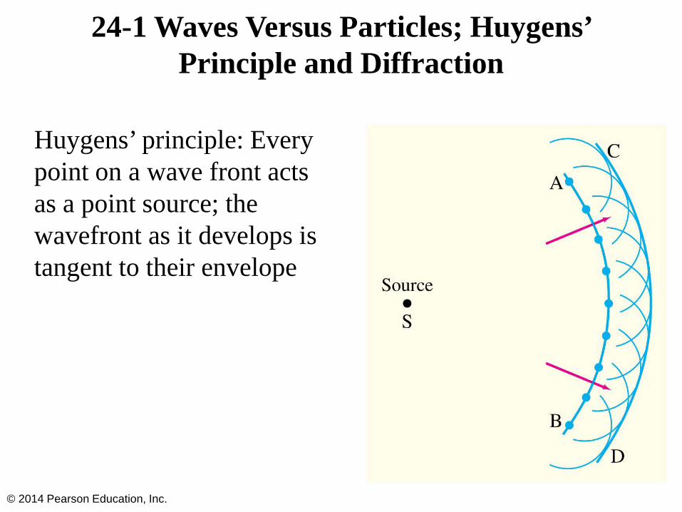
24-1 Waves Versus Particles; Huygens’ Principle and Diffraction
Huygens’ principle: Every point on a wave front acts as a point source; the wavefront as it develops is tangent to their envelope
© 2014 Pearson Education, Inc.
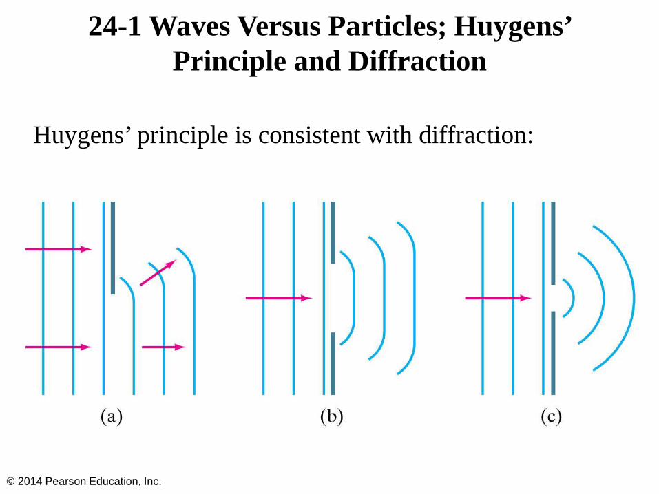
24-1 Waves Versus Particles; Huygens’ Principle and Diffraction
Huygens’ principle is consistent with diffraction:
© 2014 Pearson Education, Inc.

24-2 Huygens’ Principle and the Law of Refraction
© 2014 Pearson Education, Inc.

24-2 Huygens’ Principle and the Law of Refraction
Huygens’ principle can also explain the law of refraction.
As the wavelets propagate from each point, they propagate more slowly in the medium of higher index of refraction.
This leads to a bend in the wavefront and therefore in the ray.
© 2014 Pearson Education, Inc.

24-2 Huygens’ Principle and the Law of Refraction
The frequency of the light does not change, but the wavelength does as it travels into a new medium.
© 2014 Pearson Education, Inc.
(24-1)

24-2 Huygens’ Principle and the Law of Refraction
Highway mirages are due to a gradually changing index of refraction in heated air.
© 2014 Pearson Education, Inc.

24-3 Interference—Young’s Double-Slit Experiment
If light is a wave, interference effects will be seen, where one part of wavefront can interact with another part.
One way to study this is to do a double-slit experiment:
© 2014 Pearson Education, Inc.

24-3 Interference—Young’s Double-Slit Experiment
If light is a wave, there should be an interference pattern.
© 2014 Pearson Education, Inc.

24-3 Interference—Young’s Double-Slit Experiment
The interference occurs because each point on the screen is not the same distance from both slits. Depending on the path length difference, the wave can interfere constructively (bright spot) or destructively (dark spot).
© 2014 Pearson Education, Inc.
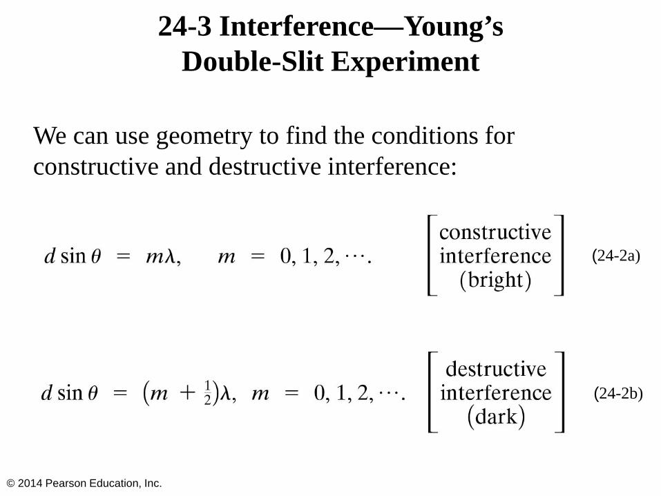
24-3 Interference—Young’s Double-Slit Experiment
We can use geometry to find the conditions for constructive and destructive interference:
© 2014 Pearson Education, Inc.
(24-2a)
(24-2b)

24-3 Interference—Young’s Double-Slit Experiment
Between the maxima and the minima, the amplitude varies smoothly.
© 2014 Pearson Education, Inc.

24-3 Interference—Young’s Double-Slit Experiment
Since the position of the maxima (except the central one) depends on wavelength, the first- and higher-order fringes contain a spectrum of colors.
© 2014 Pearson Education, Inc.

24-4 The Visible Spectrum and Dispersion
Wavelengths of visible light: 400 nm to 750 nm
Shorter wavelengths are ultraviolet; longer are infrared
© 2014 Pearson Education, Inc.

24-4 The Visible Spectrum and Dispersion
The index of refraction of a material varies somewhat with the wavelength of the light.
© 2014 Pearson Education, Inc.

24-4 The Visible Spectrum and Dispersion
This variation in refractive index is why a prism will split visible light into a rainbow of colors.
© 2014 Pearson Education, Inc.

24-4 The Visible Spectrum and Dispersion
Atmospheric rainbows are created by dispersion in tiny drops of water.
© 2014 Pearson Education, Inc.

24-5 Diffraction by a Single Slit or Disk
Light will also diffract around a single slit or obstacle.
© 2014 Pearson Education, Inc.
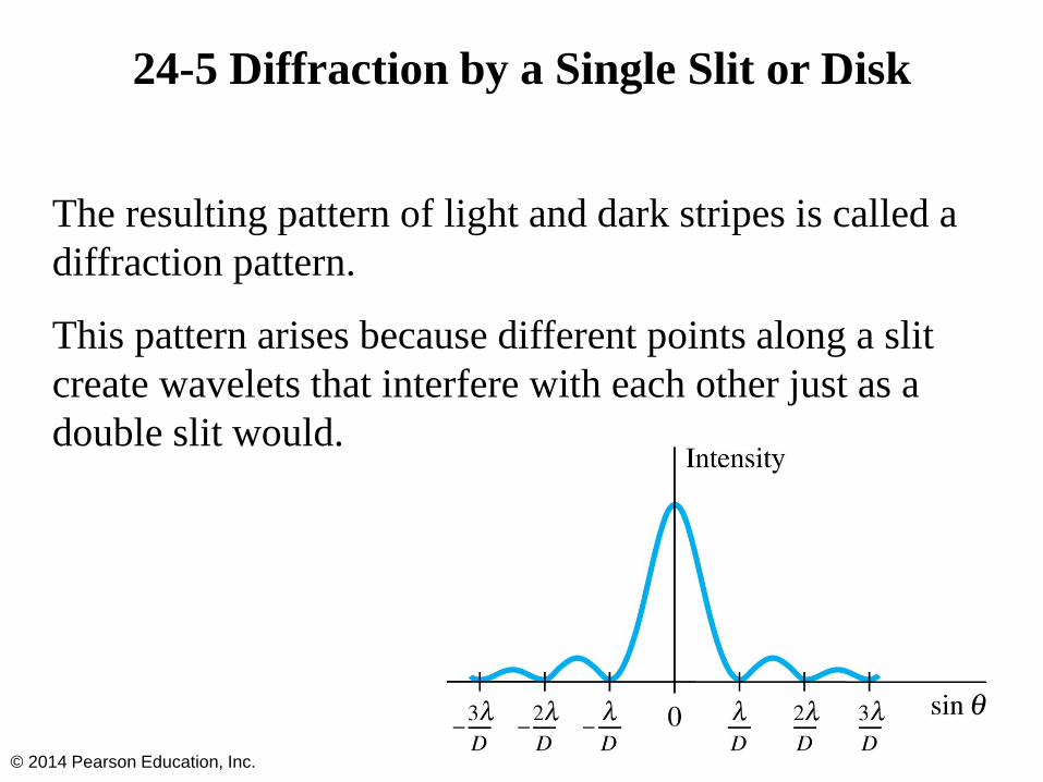
24-5 Diffraction by a Single Slit or Disk
The resulting pattern of light and dark stripes is called a diffraction pattern.
This pattern arises because different points along a slit create wavelets that interfere with each other just as a double slit would.
© 2014 Pearson Education, Inc.
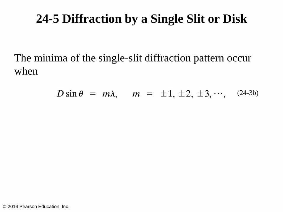
24-5 Diffraction by a Single Slit or Disk
The minima of the single-slit diffraction pattern occur when
© 2014 Pearson Education, Inc.
(24-3b)

24-6 Diffraction Grating
A diffraction grating consists of a large number of equally spaced narrow slits or lines. A transmission grating has slits, while a reflection grating has lines that reflect light.
The more lines or slits there are, the narrower the peaks.
© 2014 Pearson Education, Inc.

24-6 Diffraction Grating
The maxima of the diffraction pattern are defined by
© 2014 Pearson Education, Inc.
(24-4)
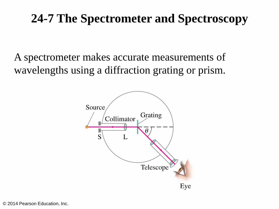
24-7 The Spectrometer and Spectroscopy
A spectrometer makes accurate measurements of wavelengths using a diffraction grating or prism.
© 2014 Pearson Education, Inc.

24-7 The Spectrometer and Spectroscopy
The wavelength can be determined to high accuracy by measuring the angle at which the light is diffracted.
Atoms and molecules can be identified when they are in a thin gas through their characteristic emission lines.
© 2014 Pearson Education, Inc.

24-8 Interference in Thin Films
Another way path lengths can differ, and waves interfere, is if the travel through different media.
If there is a very thin film of material—a few wavelengths thick—light will reflect from both the bottom and the top of the layer, causing interference.
This can be seen in soap bubbles and oil slicks, for example.
© 2014 Pearson Education, Inc.

24-8 Interference in Thin Films
The wavelength of the light will be different in the oil and the air, and the reflections at points A and B may or may not involve reflection.
© 2014 Pearson Education, Inc.

24-8 Interference in Thin Films
A similar effect takes place when a shallowly curved piece of glass is placed on a flat one. When viewed from above, concentric circles appear that are called Newton’s rings.
© 2014 Pearson Education, Inc.
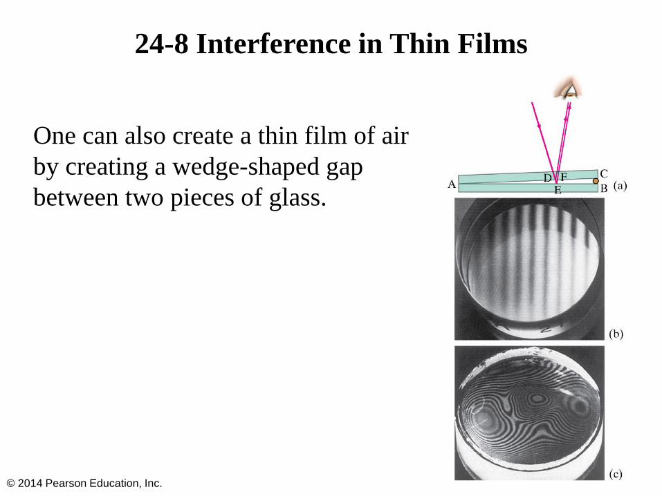
24-8 Interference in Thin Films
One can also create a thin film of air by creating a wedge-shaped gap between two pieces of glass.
© 2014 Pearson Education, Inc.

24-8 Interference in Thin Films
Problem Solving: Interference
1. Interference occurs when two or more waves arrive simultaneously at the same point in space.
2. Constructive interference occurs when the waves are in phase.
3. Destructive interference occurs when the waves are out of phase.
4. An extra half-wavelength shift occurs when light reflects from a medium with higher refractive index.
© 2014 Pearson Education, Inc.

24-9 Michelson Interferometer
The Michelson interferometer is centered around a beam splitter, which transmits about half the light hitting it and reflects the rest. It can be a very sensitive measure of length.
© 2014 Pearson Education, Inc.

24-10 Polarization
Light is polarized when its electric fields oscillate in a single plane, rather than in any direction perpendicular to the direction of propagation.
© 2014 Pearson Education, Inc.

24-10 Polarization
Polarized light will not be transmitted through a polarized film whose axis is perpendicular to the polarization direction.
© 2014 Pearson Education, Inc.

24-10 Polarization
When light passes through a polarizer, only the component parallel to the polarization axis is transmitted. If the incoming light is plane-polarized, the outgoing intensity is:
© 2014 Pearson Education, Inc.
(24-5)

24-10 Polarization
This means that if initially unpolarized light passes through crossed polarizers, no light will get through the second one.
© 2014 Pearson Education, Inc.
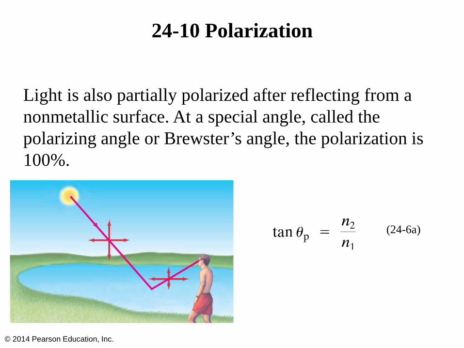
24-10 Polarization
Light is also partially polarized after reflecting from a nonmetallic surface. At a special angle, called the polarizing angle or Brewster’s angle, the polarization is 100%.
© 2014 Pearson Education, Inc.
(24-6a)
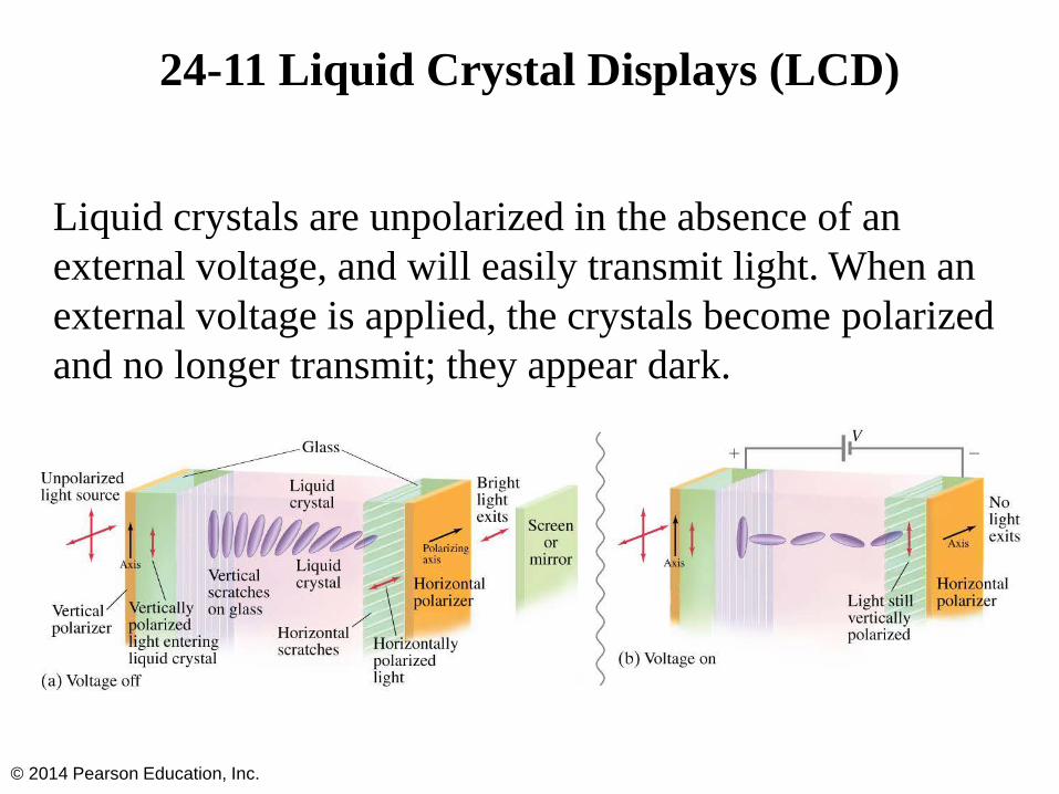
24-11 Liquid Crystal Displays (LCD)
Liquid crystals are unpolarized in the absence of an external voltage, and will easily transmit light. When an external voltage is applied, the crystals become polarized and no longer transmit; they appear dark.
© 2014 Pearson Education, Inc.

24-11 Liquid Crystal Displays (LCD)
Liquid crystals can be found in many familiar applications, such as calculators and digital watches.
Color LCD displays are more complicated; each pixel has three subpixels to provide the different colors. A source of light is behind the display (unlike calculators and watches, which use ambient light). The pixels must be able to make finer adjustments than just on and off to provide a clear image.
© 2014 Pearson Education, Inc.

24-12 Scattering of Light by the Atmosphere
Skylight is partially polarized due to scattering from molecules in the air. The amount of polarization depends on the angle that your line of sight makes with the sun.
© 2014 Pearson Education, Inc.

Summary of Chapter 24
• The wave theory of light is strengthened by the interference and diffraction of light
• Huygens’ principle: every point on a wavefront is a source of spherical wavelets
• Wavelength of light in a medium with index of refraction n:
• Young’s double-slit experiment demonstrated interference
© 2014 Pearson Education, Inc.

Summary of Chapter 24
• In the double-slit experiment, constructive interference occurs when
• and destructive interference when
• Two sources of light are coherent if they have the same frequency and maintain the same phase relationship
© 2014 Pearson Education, Inc.

Summary of Chapter 24
• Visible spectrum of light ranges from 400 nm to 750 nm (approximately)
• Index of refraction varies with wavelength, leading to dispersion
• Diffraction grating has many small slits or lines, and the same condition for constructive interference
• Wavelength can be measured precisely with a spectroscope
© 2014 Pearson Education, Inc.

Summary of Chapter 24
• Light bends around obstacles and openings in its path, yielding diffraction patterns
• Light passing through a narrow slit will produce a central bright maximum of width
• Interference can occur between reflections from the front and back surfaces of a thin film
• Light whose electric fields are all in the same plane is called plane polarized
© 2014 Pearson Education, Inc.

Summary of Chapter 24
• The intensity of plane polarized light is reduced after it passes through another polarizer:
• Light can also be polarized by reflection; it is completely polarized when the reflection angle is the polarization angle:
© 2014 Pearson Education, Inc.