lecture notes ent345 mechanical components …portal.unimap.edu.my/portal/page/portal30/lecture...a...
TRANSCRIPT
ENT345 Mechanical
Componets Design Sem 1-
2014/2015
Dr. School of Mechatronic Engineering 1
LECTURE NOTES
ENT345
MECHANICAL COMPONENTS DESIGN
Lecture 5
8/10/2014
GEAR
Dr. HAFTIRMAN
MECHANICAL ENGINEEERING PROGRAM
SCHOOL OF MECHATRONIC ENGINEERING
UniMAP
COPYRIGHT©RESERVED 2014

Outline
TYPE OF GEARS
SPURS AND HELICAL GEARS
INTERFERENCE
THE LEWIS BENDING EQUATION
ENT345 Mechanical
Componets Design Sem 1-
2014/2015
Dr. School of Mechatronic Engineering 2
Gear
CO1:
ABILITY TO DESIGN OF MEHANICAL
COMPONENTS IN MECHANICAL SYSTEMS
ENT345 Mechanical
Componets Design Sem 1-
2014/2015
Dr. School of Mechatronic Engineering 3

Gear
A gear is a component within a transmission device that transmits rotational force to another gear or device.
A gear is different from a pulley in that a gear is a round wheel that has linkages ("teeth" or "cogs") that mesh with other gear teeth, allowing force to be fully transferred without slippage.
Depending on their construction and arrangement, geared devices can transmit forces at different speeds, torques, or in a different direction, from the power source.
ENT345 Mechanical
Componets Design Sem 1-
2014/2015
Dr. School of Mechatronic Engineering 4

Gear
The most common situation is for a gear to mesh with another gear, but a gear can mesh with any device having compatible teeth, such as linear moving racks.
The gear's most important feature is that gears of unequal sizes (diameters) can be combined to produce a mechanical advantage, so that the rotational speed and torque of the second gear are different from those of the first. In the context of a particular machine, the term "gear" also refers to one particular arrangement of gears among other arrangements (such as "first gear"). Such arrangements are often given as a ratio, using the number of teeth or gear diameter as units.
ENT345 Mechanical
Componets Design Sem 1-
2014/2015
Dr. School of Mechatronic Engineering 5
Gear
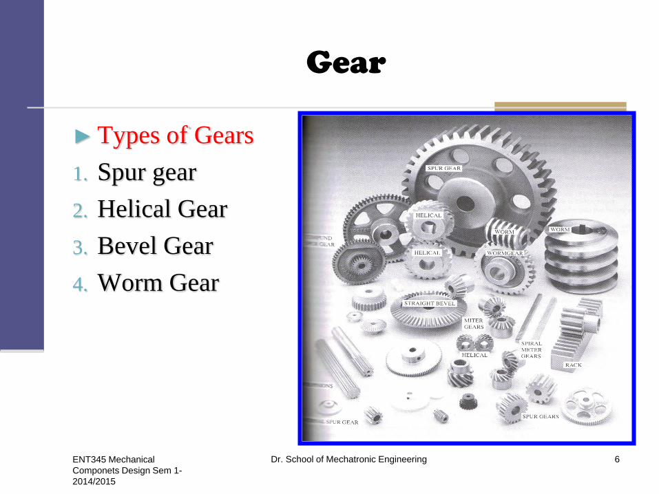
► Types of Gears
1. Spur gear
2. Helical Gear
3. Bevel Gear
4. Worm Gear
ENT345 Mechanical
Componets Design Sem 1-
2014/2015
Dr. School of Mechatronic Engineering 6
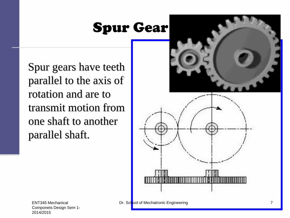
Spur Gear
Spur gears have teeth
parallel to the axis of
rotation and are to
transmit motion from
one shaft to another
parallel shaft.
ENT345 Mechanical
Componets Design Sem 1-
2014/2015
Dr. School of Mechatronic Engineering 7

Spur Gear
ENT345 Mechanical
Componets Design Sem 1-
2014/2015
Dr. School of Mechatronic Engineering 8
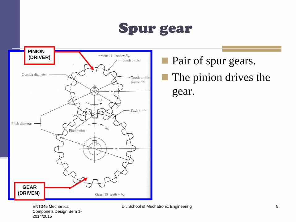
Spur gear
Pair of spur gears.
The pinion drives the
gear.
PINION
(DRIVER)
GEAR
(DRIVEN)
ENT345 Mechanical
Componets Design Sem 1-
2014/2015
Dr. School of Mechatronic Engineering 9
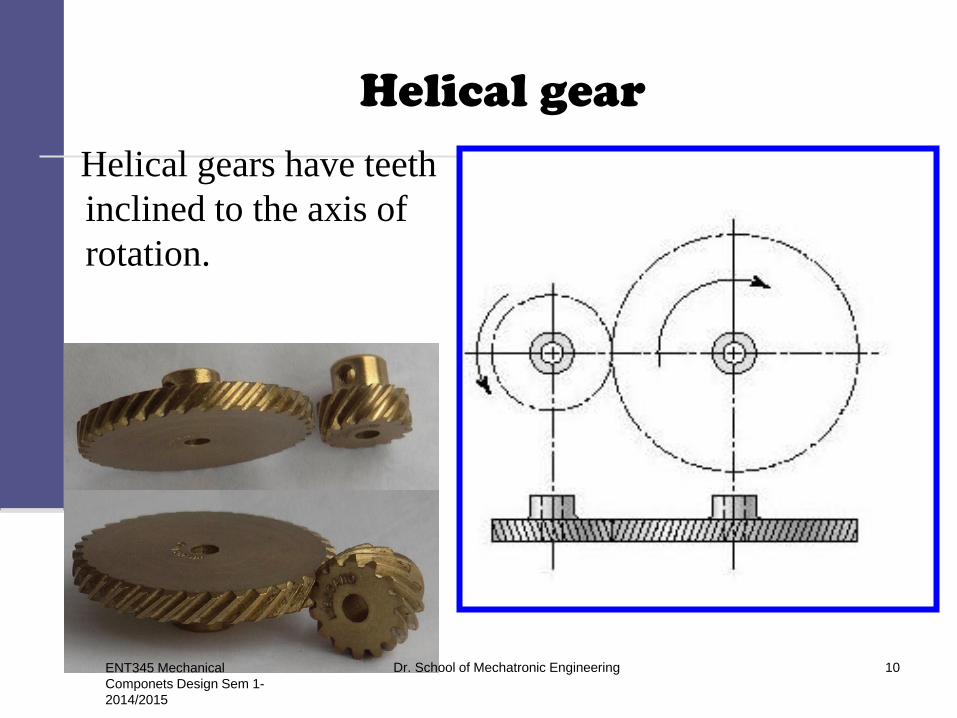
Helical gear
Helical gears have teeth
inclined to the axis of
rotation.
ENT345 Mechanical
Componets Design Sem 1-
2014/2015
Dr. School of Mechatronic Engineering 10

Bevel gear
► Bevel gears have teeth
formed on conical
surfaces and are used
mostly for transmitting
motion between
intersecting shaft.
ENT345 Mechanical
Componets Design Sem 1-
2014/2015
Dr. School of Mechatronic Engineering 11

Worm gear
The direction of rotation
of the worm gear, also
called the worm wheel,
depends upon the
direction of rotation of
the worm and upon
whether the worm teeth
are cut right-hand or
left-hand.
ENT345 Mechanical
Componets Design Sem 1-
2014/2015
Dr. School of Mechatronic Engineering 12

Rack and pinion
A rack is a toothed bar or rod that can be thought of as a sector gear with an infinitely large radius of curvature. Torque can be converted to linear force by meshing a rack with a pinion: the pinion turns; the rack moves in a straight line.
Racks also feature in the theory of gear geometry, where, for instance, the tooth shape of an interchangeable set of gears may be specified for the rack (infinite radius), and the tooth shapes for gears of particular actual radii then derived from that.
ENT345 Mechanical
Componets Design Sem 1-
2014/2015
Dr. School of Mechatronic Engineering 13
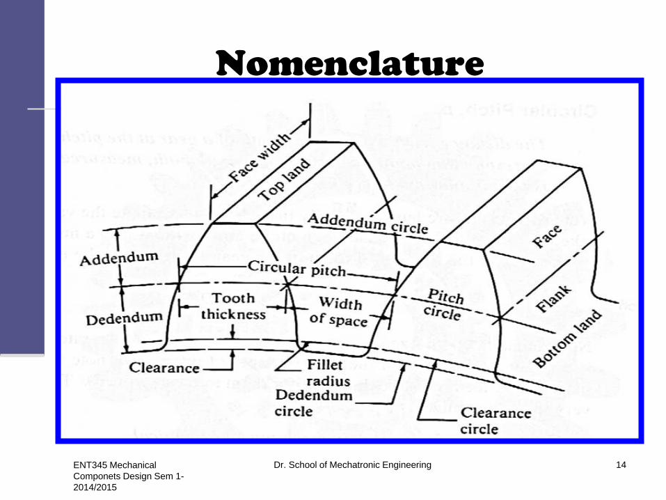
Nomenclature
ENT345 Mechanical
Componets Design Sem 1-
2014/2015
Dr. School of Mechatronic Engineering 14
Nomenclature
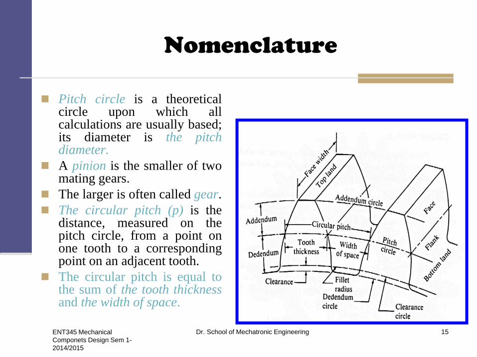
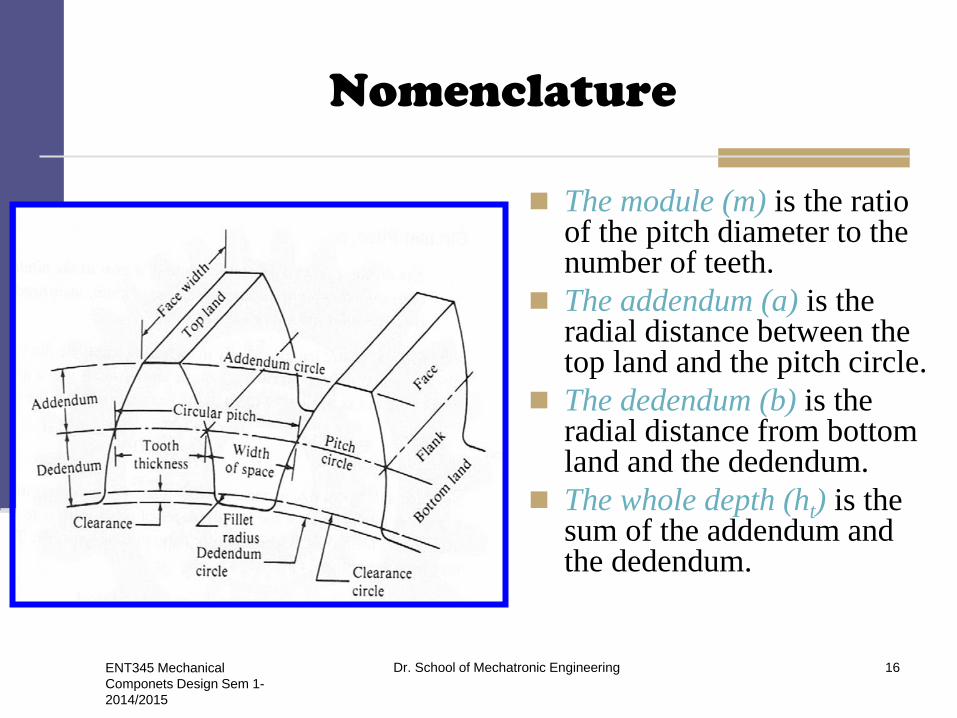
Pitch circle is a theoretical circle upon which all calculations are usually based; its diameter is the pitch diameter.
A pinion is the smaller of two mating gears.
The larger is often called gear.
The circular pitch (p) is the distance, measured on the pitch circle, from a point on one tooth to a corresponding point on an adjacent tooth.
The circular pitch is equal to the sum of the tooth thickness and the width of space.
ENT345 Mechanical
Componets Design Sem 1-
2014/2015
Dr. School of Mechatronic Engineering 15
Nomenclature
The module (m) is the ratio of the pitch diameter to the number of teeth.
The addendum (a) is the radial distance between the top land and the pitch circle.
The dedendum (b) is the radial distance from bottom land and the dedendum.
The whole depth (ht) is the sum of the addendum and the dedendum.
ENT345 Mechanical
Componets Design Sem 1-
2014/2015
Dr. School of Mechatronic Engineering 16

bDdiamterrootD
aDdiamteroutsideD
R
o
2
2
abcclearancec
aaadepthworkingh
chbadepthwholeh
k
kt
2
P
pthicknesstootht
22
2
GP ddC
ENT345 Mechanical
Componets Design Sem 1-
2014/2015
Dr. School of Mechatronic Engineering 17

Nomenclature
The clearance circle is a circular that is tangent to addendum circle of mating gear.
The clearance ( c ) is gear exceeding the sum of addendum and the dedendum.
The backlash is the amount by which the width of a tooth space exceeds the thickness of the engaging tooth measured on the pitch circles.
ENT345 Mechanical
Componets Design Sem 1-
2014/2015
Dr. School of Mechatronic Engineering 18

Fundamental
P = diametral pitch, teeth
per inch
m = module, mm.
d = pitch diameter, mm
N= number of teeth.
p =circular pitch
N
dm
mN
dp
d
NP
pPmm
Pm
inP
m
4.25
1
ENT345 Mechanical
Componets Design Sem 1-
2014/2015
Dr. School of Mechatronic Engineering 19

Standard modules
ENT345 Mechanical
Componets Design Sem 1-
2014/2015
Dr. School of Mechatronic Engineering 20

ENT345 Mechanical
Componets Design Sem 1-
2014/2015
Dr. School of Mechatronic Engineering 21

Tooth systems
A tooth system is a standard that specifies the
relationships involving addendum, dedendum, working
depth, tooth thickness and pressure angle.
ENT345 Mechanical
Componets Design Sem 1-
2014/2015
Dr. School of Mechatronic Engineering 22
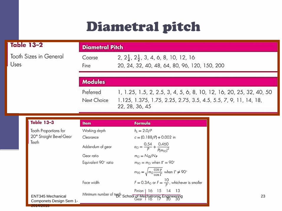
Diametral pitch
ENT345 Mechanical
Componets Design Sem 1-
2014/2015
Dr. School of Mechatronic Engineering 23
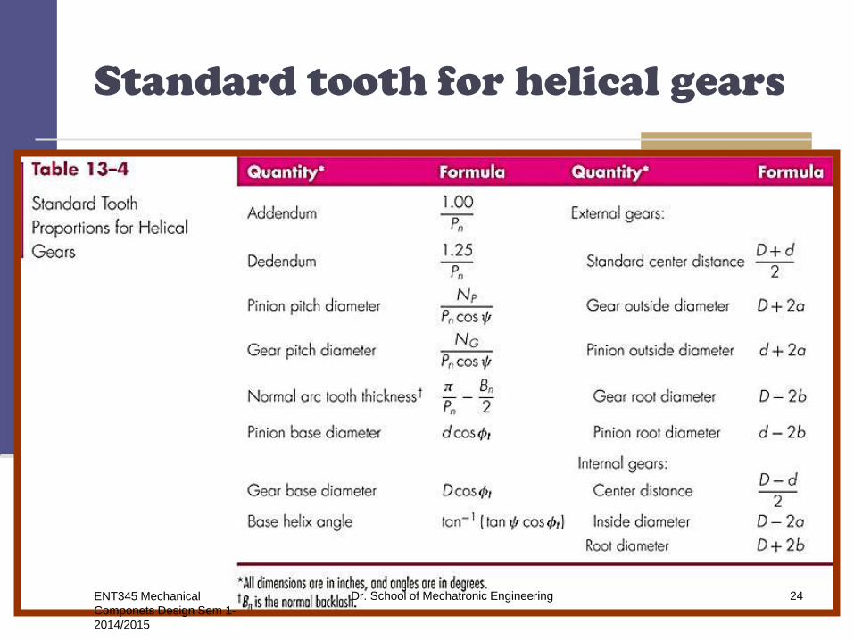
Standard tooth for helical gears
ENT345 Mechanical
Componets Design Sem 1-
2014/2015
Dr. School of Mechatronic Engineering 24

Problem
Problem 13-1
A 17-tooth spur pinion has a
diametral pitch of 8 teeth/in,
runs at 1120 rev/min, and drives
a gear at a speed of 544
rev/min.
Find the number of teeth on the
gear and the theoretical center-
to-center distance.
Problem 13-2
A 15-tooth spur pinion has a module
of 3mm and runs at a speed of
1600 rev/min. The driven gear has
60 teeth. Find the speed of the
driven gear, the circular pitch, and
the theoretical center-to-center
distance.
Solution
inC
teethPdN
inindn
nd
inP
Nd
GG
PG
p
P
25.32
)375.4125.2(
35)375.4(8
375.4)125.2(544
1120
125.28
17
3
2
mmC
mmmp
revnG
5.1122
)6015(3
3
min/40060
151600
ENT345 Mechanical
Componets Design Sem 1-
2014/2015
Dr. School of Mechatronic Engineering 25

Fundamental
The pitch-line velocity
2211 rrV
1
2
2
1
r
r
ENT345 Mechanical
Componets Design Sem 1-
2014/2015
Dr. School of Mechatronic Engineering 26

Problem 13-3 A spur gearset has a module of 4mm and a velocity ratio of
2.80. The pinion has 20 teeth.
Find the number of teeth on the driven gear, the pitch
diameter, and the theoretical center-to-center distance.
Solution
mmdd
C
mmmNd
mmmNd
teethNN
GP
PP
GG
PG
1522
22480
2
80)4)(20(
224)4)(56(
56)80.2(20)80.2(
ENT345 Mechanical
Componets Design Sem 1-
2014/2015
Dr. School of Mechatronic Engineering 27

Fundamental
Suppose we specify that an 18-tooth
pinion is to mesh with a 30-tooth
gear and that the diametral pitch of
the gear set is to be 2 teeth per inch.
The pitch diameters of the pinion and
gear are
The center distance is the sum of the
pitch radii,
inr
inP
Nd
inr
inP
Nd
5.7
152
30
5.4
92
18
2
22
1
11
inininrr 125.75.421 28 ENT345 Mechanical
Componets Design Sem 1-
2014/2015
Dr. School of Mechatronic Engineering

Fundamental
The construct the pitch circles of radii r1 and r2. These are tangent at P, the pitch point.
Next draw line ab, common tangent, through the pitch point.
We designate gear 1 as the driver (CCW).
We draw a line cd through point P at an angle Ø to the common tangent ab.
The line cd has three names; namely the pressure line, the generating line, and the line of action.
Dr. School of Mechatronic Engineering 29 ENT345 Mechanical
Componets Design Sem 1-
2014/2015
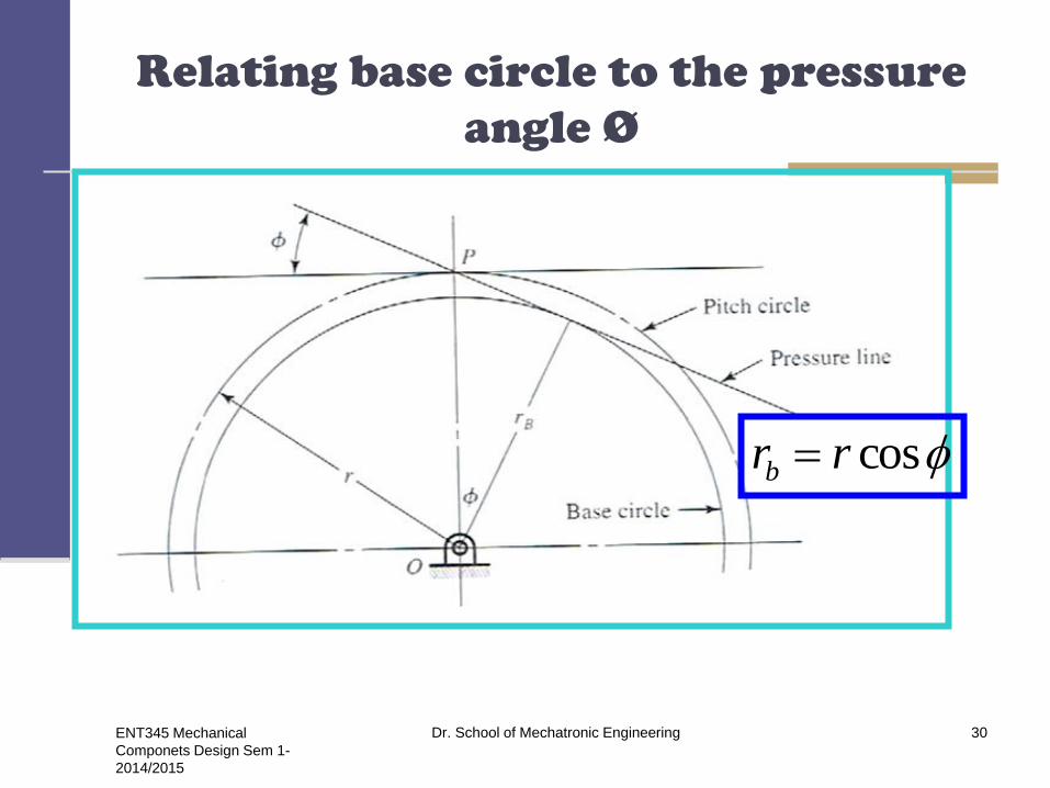
Relating base circle to the pressure
angle Ø
cosrrb
ENT345 Mechanical
Componets Design Sem 1-
2014/2015
Dr. School of Mechatronic Engineering 30
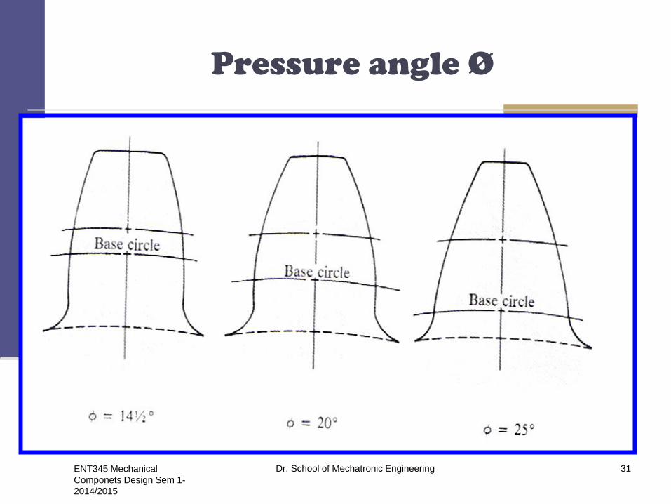
Pressure angle Ø
ENT345 Mechanical
Componets Design Sem 1-
2014/2015
Dr. School of Mechatronic Engineering 31
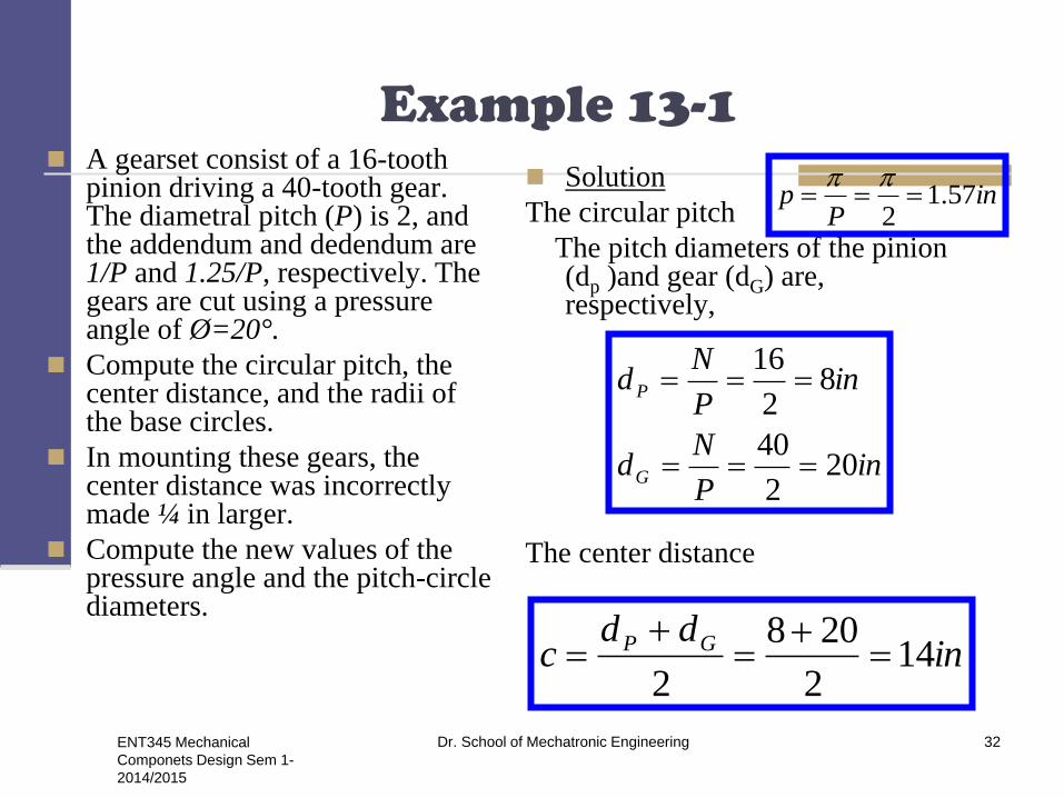
Example 13-1
A gearset consist of a 16-tooth pinion driving a 40-tooth gear. The diametral pitch (P) is 2, and the addendum and dedendum are 1/P and 1.25/P, respectively. The gears are cut using a pressure angle of Ø=20°.
Compute the circular pitch, the center distance, and the radii of the base circles.
In mounting these gears, the center distance was incorrectly made ¼ in larger.
Compute the new values of the pressure angle and the pitch-circle diameters.
Solution
The circular pitch
The pitch diameters of the pinion (dp )and gear (dG) are, respectively,
The center distance
inP
p 57.12
inP
Nd
inP
Nd
G
P
202
40
82
16
indd
c GP 142
208
2
ENT345 Mechanical
Componets Design Sem 1-
2014/2015
Dr. School of Mechatronic Engineering 32

Example 13-1
Pressure angle 20°, the base-circle
radii is
Designating d’p and d’
G as the new
pitch-circle diameters, the ¼ in
increase in the center distance
requires that
The velocity ratio does not
change,
The new pressure angle Ø
ingearr
inpinionr
rr
B
B
B
40.920cos2
20)(
76.320cos2
8)(
cos
indd GP 25.14
2
''
ind
indd
dd
P
GG
GG
143.8)357.20(4.0
357.205.284.1
25.142
4.0
'
''
''
56.222/143.8
76.3cos
2/
)(cos
cos
1
'
1'
P
b
b
d
pinionr
rr
ENT345 Mechanical
Componets Design Sem 1-
2014/2015
Dr. School of Mechatronic Engineering 33
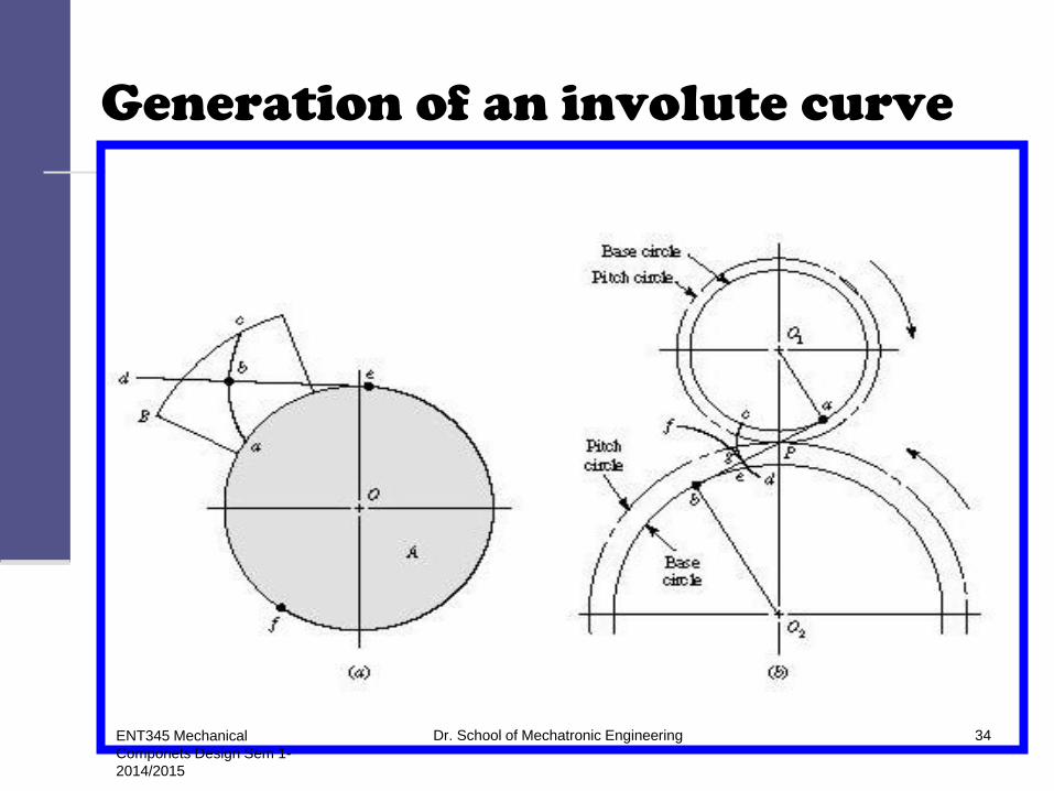
Generation of an involute curve
ENT345 Mechanical
Componets Design Sem 1-
2014/2015
Dr. School of Mechatronic Engineering 34

Construction of an involute
ENT345 Mechanical
Componets Design Sem 1-
2014/2015
Dr. School of Mechatronic Engineering 35

Involute
The involute gear profile is the most commonly used system for gearing today. In an involute gear, the profiles of the teeth are involutes of a circle.
The involute of a circle is the spiraling curve traced by the end of an imaginary taut string unwinding itself from that stationary circle.
ENT345 Mechanical
Componets Design Sem 1-
2014/2015
Dr. School of Mechatronic Engineering 36

Involute
Equations of an involute of a
parametrical define curve are:
22
2'2
22
22
''
''
],[
''
'''
],[
yx
dtyxy
yyxY
yx
dtyxtx
xyxX
t
a
t
a
ENT345 Mechanical
Componets Design Sem 1-
2014/2015
Dr. School of Mechatronic Engineering 37

Tooth contact nomenclature
ENT345 Mechanical
Componets Design Sem 1-
2014/2015
Dr. School of Mechatronic Engineering 38

Point of contact
Path of Action,
ANSI/AGMA 1012-G05
A point of contact is any
point at which two tooth
profiles touch each
other.
ENT345 Mechanical
Componets Design Sem 1-
2014/2015
Dr. School of Mechatronic Engineering 39

Plane of action
Surface of action
The surface of action is the imaginary surface in which contact occurs between two engaging tooth surfaces. It is the summation of the paths of action in all sections of the engaging teeth.
Plane of Action, ANSI/AGMA 1012-G05
The plane of action is the surface of action for involute, parallel axis gears with either spur or helical teeth. It is tangent to the base cylinders.
ENT345 Mechanical
Componets Design Sem 1-
2014/2015
Dr. School of Mechatronic Engineering 40

Line of contact
Line of Contact,
ANSI/AGMA 1012-G05
A line of contact is a
line or curve along
which two tooth
surfaces are tangent to
each other.
ENT345 Mechanical
Componets Design Sem 1-
2014/2015
Dr. School of Mechatronic Engineering 41

Zone of action (contact zone)
Zone of Action, ANSI/AGMA
1012-G05
Zone of action (contact zone)
for involute, parallel-axis
gears with either spur or
helical teeth, is the
rectangular area in the plane
of action bounded by the
length of action and the
effective face width.
ENT345 Mechanical
Componets Design Sem 1-
2014/2015
Dr. School of Mechatronic Engineering 42

Path of contact
Lines of Contact (helical gear), ANSI/AGMA 1012-G05
The path of contact is the curve on either tooth surface along which theoretical single point contact occurs during the engagement of gears with crowned tooth surfaces or gears that normally engage with only single point contact.
ENT345 Mechanical
Componets Design Sem 1-
2014/2015
Dr. School of Mechatronic Engineering 43

Length of action
Length of Action,
ANSI/AGMA 1012-G05
Length of action is the
distance on the line of
action through which the
point of contact moves
during the action of the
tooth profile.
ENT345 Mechanical
Componets Design Sem 1-
2014/2015
Dr. School of Mechatronic Engineering 44
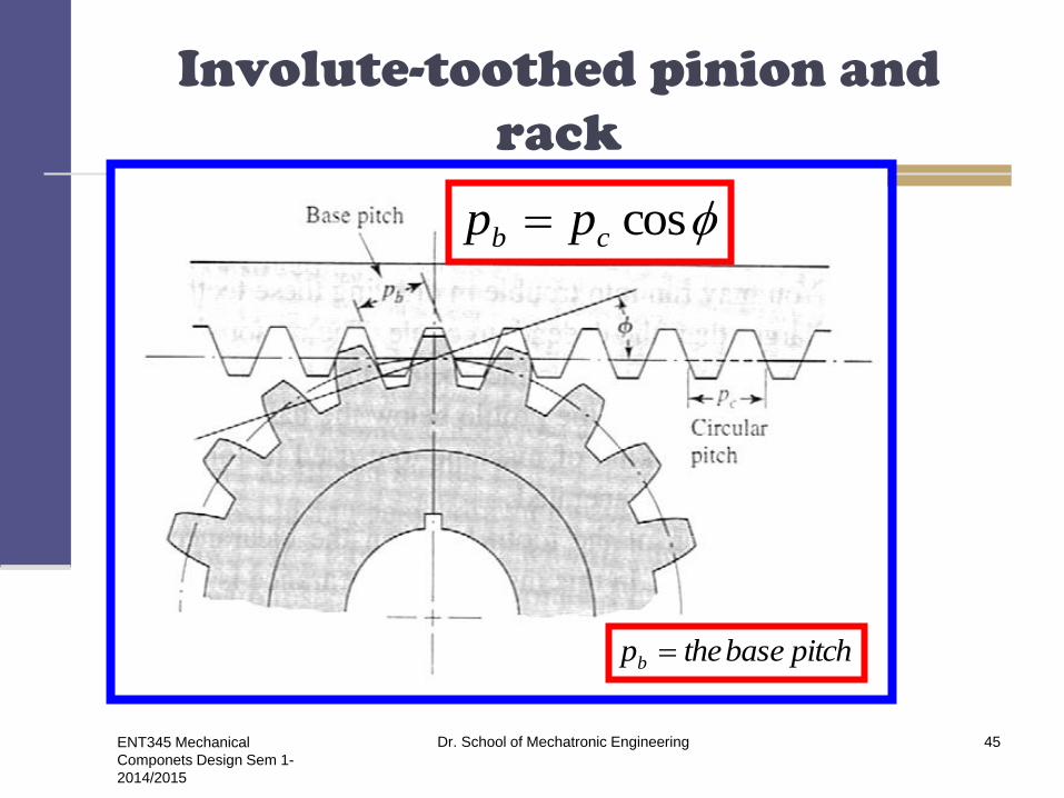
Involute-toothed pinion and
rack
coscb pp
pitchbasethepb
ENT345 Mechanical
Componets Design Sem 1-
2014/2015
Dr. School of Mechatronic Engineering 45

Internal gear and pinion
ENT345 Mechanical
Componets Design Sem 1-
2014/2015
Dr. School of Mechatronic Engineering 46

Contact ratio (mc)
p
qm t
c
cosp
Lm ab
c
)( tt qactionofarctheq
ENT345 Mechanical
Componets Design Sem 1-
2014/2015
Dr. School of Mechatronic Engineering 47
Problem 13-4
A 21-tooth spur pinion mates with a 28-tooth gear.
The diametral pitch is 3 teeth/in and the pressure
angle is 20°. Make a drawing of the gears showing
one tooth on each gear.
Find the addendum (a), dedendum (b), clearance
(c), circular pitch (p), tooth thickness (t), and base-
circle diameters; the lengths of the arc approach,
recess, and action; and the base pitch and contact
ratio.
ENT345 Mechanical
Componets Design Sem 1-
2014/2015
Dr. School of Mechatronic Engineering 48

indd
inP
Nd
Pinion
inp
t
inP
p
inabc
inP
b
inP
a
b 578.620cos720cos
73
21
523.02
047.1
2
047.13
0834.03333.04167.0
4167.03
25.125.1
333.03
11
11
11
55.1984.0
53.1
984.020cos3
cos
770.820cos333.9
333.93
28
2
22
b
ab
c
cb
b
P
Lm
ratioContact
inpp
pitchBase
ind
inP
Nd
ENT345 Mechanical Componets
Design Sem 1-2014/2015
Dr. School of Mechatronic Engineering 49

Gear ratio
The gear ratio is the relationship between the number of teeth on two gears that are meshed or two sprockets connected with a common roller chain, or the circumferences of two pulleys connected with a drive belt.
In the picture to the right, the smaller gear (known as the pinion) has 13 teeth, while the second, larger gear (known as the idler gear) has 21 teeth. The gear ratio is therefore 13/21 or 1/1.62 (also written as 1:1.62).
This means that for every one revolution of the pinion, the gear has made 1/1.62, or 0.62, revolutions. In practical terms, the gear turns more slowly. Suppose the largest gear in the picture has 42 teeth, the gear ratio between the second and third gear is thus 21/42 = 1/2, and for every revolution of the smallest gear the largest gear has only turned 0.62/2 = 0.31 revolution, a total reduction of about 1:3.23.
ENT345 Mechanical
Componets Design Sem 1-
2014/2015
Dr. School of Mechatronic Engineering 50

Gear ratio
1st gear 2.97:1
2nd gear 2.07:1
3rd gear 1.43:1
4th gear 1.00:1
5th gear 0.84:1
6th gear 0.56:1
reverse 3.28:1
ENT345 Mechanical
Componets Design Sem 1-
2014/2015
Dr. School of Mechatronic Engineering 51
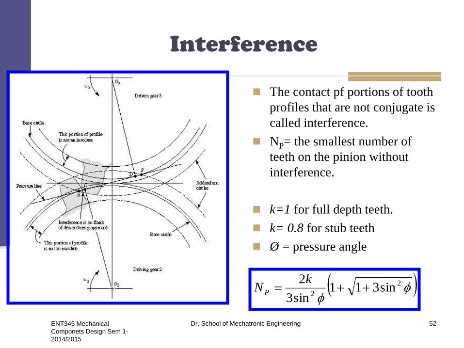
Interference
The contact pf portions of tooth
profiles that are not conjugate is
called interference.
NP= the smallest number of
teeth on the pinion without
interference.
k=1 for full depth teeth.
k= 0.8 for stub teeth
Ø = pressure angle
2
2sin311
sin3
2
kNP
ENT345 Mechanical
Componets Design Sem 1-
2014/2015
Dr. School of Mechatronic Engineering 52
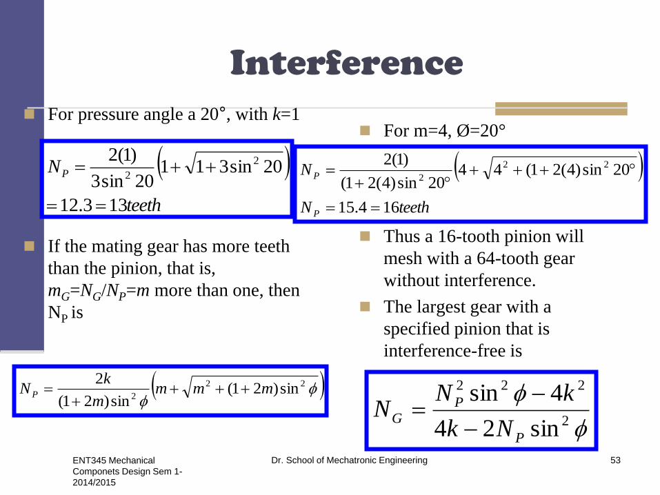
Interference
For pressure angle a 20°, with k=1
If the mating gear has more teeth
than the pinion, that is,
mG=NG/NP=m more than one, then
NP is
For m=4, Ø=20°
Thus a 16-tooth pinion will
mesh with a 64-tooth gear
without interference.
The largest gear with a
specified pinion that is
interference-free is
22
2sin)21(
sin)21(
2mmm
m
kNP
teeth
NP
133.12
20sin31120sin3
)1(2 2
2
teethN
N
P
P
164.15
20sin)4(21(4420sin)4(21(
)1(2 22
2
2
222
sin24
4sin
P
PG
Nk
kNN
ENT345 Mechanical
Componets Design Sem 1-
2014/2015
Dr. School of Mechatronic Engineering 53

Interference
For a 13-tooth pinion with a pressure angle Ø of 20°
For a 13-tooth spur pinion, the maximum number of gear teeth.
possible without interference is 16.
The smallest spur pinion that will a rack without interference is
For a 20° pressure angle full-depth tooth the smallest number of pinion
teeth to mesh with a rack is
teethNG 1645.1620sin)13(2)1(4
)1(420sin132
222
2sin
)(2 kN P teethNP 181.17
20sin
)1(22
ENT345 Mechanical
Componets Design Sem 1-
2014/2015
Dr. School of Mechatronic Engineering 54

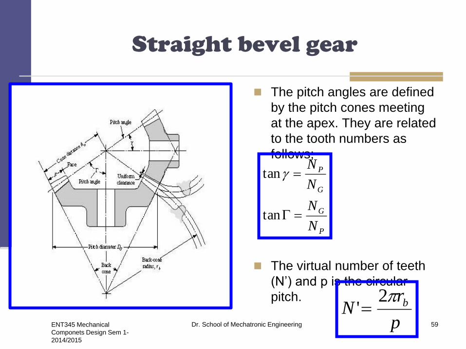
Straight bevel gear
The pitch angles are defined by
the pitch cones meeting at the
apex. They are related to the
tooth numbers as follows;
The virtual number of teeth
(N’) and p is the circular pitch.
P
G
G
P
N
N
N
N
tan
tan
p
rN b2
'
ENT345 Mechanical
Componets Design Sem 1-
2014/2015
Dr. School of Mechatronic Engineering 55
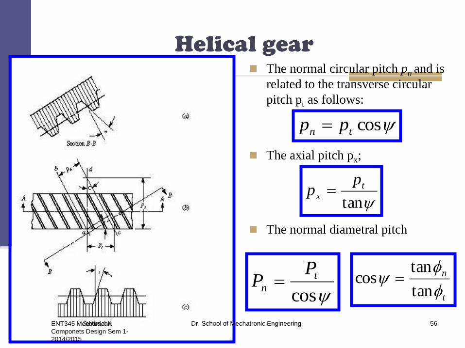
Helical gear The normal circular pitch pn and is
related to the transverse circular
pitch pt as follows:
The axial pitch px;
The normal diametral pitch
costn pp
tan
t
x
pp
cos
t
n
PP
t
n
tan
tancos
ENT345 Mechanical
Componets Design Sem 1-
2014/2015
Dr. School of Mechatronic Engineering 56
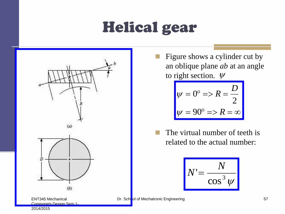
Helical gear
Figure shows a cylinder cut by
an oblique plane ab at an angle
to right section.
The virtual number of teeth is
related to the actual number:
R
DR
90
20
3cos'
NN
ENT345 Mechanical
Componets Design Sem 1-
2014/2015
Dr. School of Mechatronic Engineering 57
Helical gears
ENT345 Mechanical
Componets Design Sem 1-
2014/2015
Dr. School of Mechatronic Engineering 58
ENT345 Mechanical
Componets Design Sem 1-
2014/2015
Dr. School of Mechatronic Engineering 59
Straight bevel gear
The pitch angles are defined
by the pitch cones meeting
at the apex. They are related
to the tooth numbers as
follows;
The virtual number of teeth
(N’) and p is the circular
pitch.
P
G
G
P
N
N
N
N
tan
tan
p
rN b2
'

ENT345 Mechanical
Componets Design Sem 1-
2014/2015
Dr. School of Mechatronic Engineering 60
Helical gear
The normal circular pitch pn
and is related to the
transverse circular pitch pt as
follows:
The axial pitch px;
The normal diametral pitch
costn pp
tan
t
x
pp
cos
t
n
PP
t
n
tan
tancos
n
ttp
np
xp
ENT345 Mechanical
Componets Design Sem 1-
2014/2015
Dr. School of Mechatronic Engineering 61
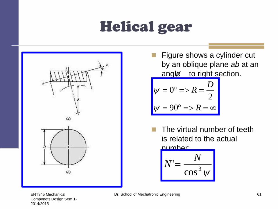
Helical gear
Figure shows a cylinder cut
by an oblique plane ab at an
angle to right section.
The virtual number of teeth
is related to the actual
number:
R
DR
90
20
3cos'
NN

ENT345 Mechanical
Componets Design Sem 1-
2014/2015
Dr. School of Mechatronic Engineering 62
Helical gear
The pressure angle Øt
teethN
kN
P
t
t
t
t
P
n
t
948.880.22sin31180.22sin3
30cos)1(2
80.2230cos
20tantan
30,20
sin311sin3
cos2
cos
tantan
2
2
1
2
2
1
.125.1180.22sin
30cos)1(2
80.22,30,20
sin
cos2
1202.1280.22sin)9(230cos)1(4
30cos)1(480.22sin9
80.22,30,20
sin2cos4
cos4sin
2
2
2222
2
2222
teethN
kN
N
Nk
kNN
mN
Nm
P
tn
t
P
G
tn
tP
tP
P
P
GG

ENT345 Mechanical
Componets Design Sem 1-
2014/2015
Dr. School of Mechatronic Engineering 63
Worm gears
dG= the pitch diameter
NG= the number of teeth
pt= the transverse circular
pitch.
px= the axial pitch
λ= the lead angle
Ψ = the helix angle
tG
G
pNd
ENT345 Mechanical
Componets Design Sem 1-
2014/2015
Dr. School of Mechatronic Engineering 64
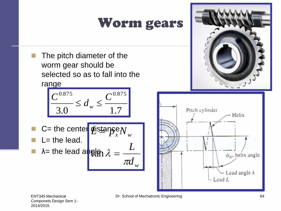
Worm gears
The pitch diameter of the
worm gear should be
selected so as to fall into the
range
C= the center distance.
L= the lead.
λ= the lead angle
7.10.3
875.0875.0 Cd
Cw
w
wx
d
L
NpL
tan

ENT345 Mechanical
Componets Design Sem 1-
2014/2015
Dr. School of Mechatronic Engineering 65
Worm gears

ENT345 Mechanical
Componets Design Sem 1-
2014/2015
Dr. School of Mechatronic Engineering 66
Gear train
A gear train is a set or system of gears arranged to transfer rotational torque from one part of a mechanical system to another.
Gear trains consists of:
Driving gears - attached to the input shaft.
Driven gears/Motor gears - attached to the output shaft.
Idler gears - interposed between the driving and driven gear in
order to maintain the direction of the output shaft the same as the
input shaft or to increase the distance between the drive and
driven gears.
A compound gear train refers to two or more gears
used to transmit motion.

ENT345 Mechanical
Componets Design Sem 1-
2014/2015
Dr. School of Mechatronic Engineering 67
Gear train

ENT345 Mechanical
Componets Design Sem 1-
2014/2015
Dr. School of Mechatronic Engineering 68
Gear train
5
4
4
3
2
1
1
5
N
N
N
N
N
N
n
n
The speed ratio between
gear 5 and 1 The minus signs indicate that the
pinion and gear rotate in opposite
directions

ENT345 Mechanical
Componets Design Sem 1-
2014/2015
Dr. School of Mechatronic Engineering 69
Gear train
Consider a pinion 2 driving a
gear 3.
The speed of the driven gear
is
d= pitch diameter
Gears 2, 3, and 5 are
drivers.
Gears 3, 4, and 6 are driven
members.
2
3
22
3
23 n
d
dn
N
Nn
2
6
5
4
3
3
26 n
N
N
N
N
N
Nn
ENT345 Mechanical
Componets Design Sem 1-
2014/2015
Dr. School of Mechatronic Engineering 70
Gear train
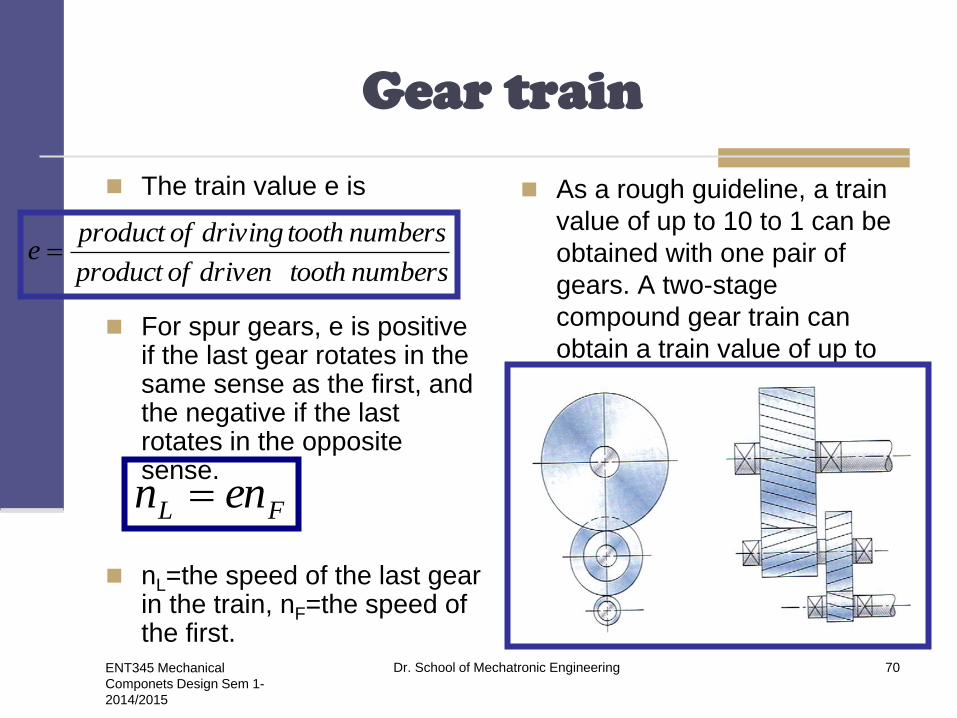
The train value e is
For spur gears, e is positive if the last gear rotates in the same sense as the first, and the negative if the last rotates in the opposite sense.
nL=the speed of the last gear in the train, nF=the speed of the first.
As a rough guideline, a train
value of up to 10 to 1 can be
obtained with one pair of
gears. A two-stage
compound gear train can
obtain a train value of up to
100 to 1.
numberstoothdrivenofproduct
numberstoothdrivingofproducte
FL enn

ENT345 Mechanical
Componets Design Sem 1-
2014/2015
Dr. School of Mechatronic Engineering 71
Example 13-4
teethN
N
P
P
164.15
20sin)4(21(4420sin)4(21(
)1(2 22
2
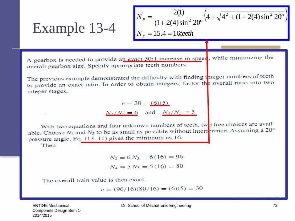
In a two-stage compound gear
train, assign the square root of
the over all train value to each
stage
ENT345 Mechanical
Componets Design Sem 1-
2014/2015
Dr. School of Mechatronic Engineering 72
Example 13-4
teethN
N
P
P
164.15
20sin)4(21(4420sin)4(21(
)1(2 22
2
ENT345 Mechanical
Componets Design Sem 1-
2014/2015
Dr. School of Mechatronic Engineering 73
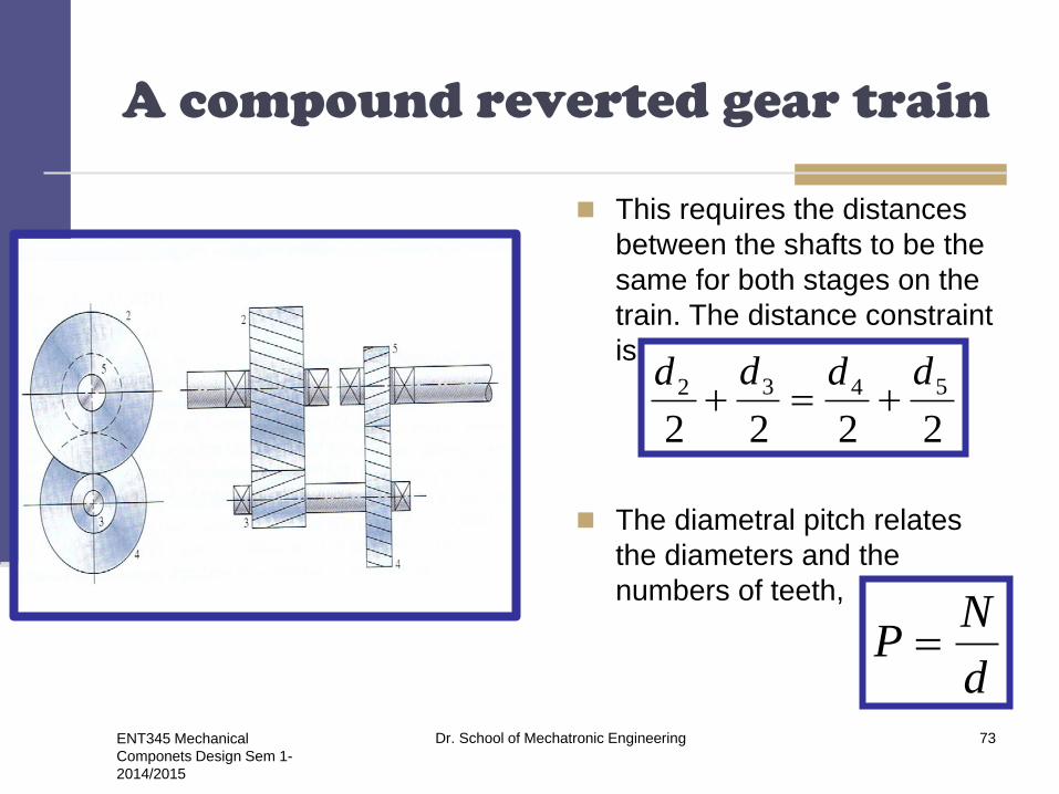
A compound reverted gear train
This requires the distances
between the shafts to be the
same for both stages on the
train. The distance constraint
is
The diametral pitch relates
the diameters and the
numbers of teeth,
2222
5432 dddd
d
NP

ENT345 Mechanical
Componets Design Sem 1-
2014/2015
Dr. School of Mechatronic Engineering 74
A compound reverted gear train
Replacing all the diameters
gives
Assuming a constant
diametral pitch in both
stages, and the geometry
condition stated in terms of
numbers of teeth:
)2()2()2()2(
5432
P
N
P
N
P
N
P
N
5432 NNNN

ENT345 Mechanical
Componets Design Sem 1-
2014/2015
Dr. School of Mechatronic Engineering 75
Planetary gear train

ENT345 Mechanical
Componets Design Sem 1-
2014/2015
Dr. School of Mechatronic Engineering 76
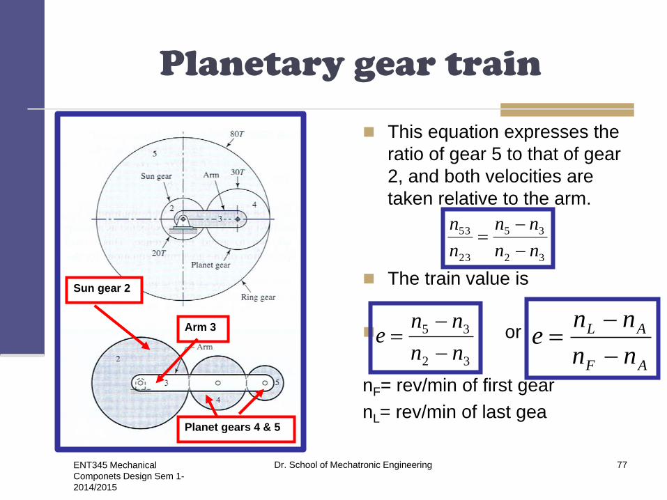
Planetary gear train
Planetary trains always
include a sun gear, a planet
carrier or arm, and one or
more planet gears.
A planetary train composed
af s sun gear 2, an arm or
carrier 3, and planet gears 4
and 5. The angular velocity
of gear 2 relative to the arm
in rev/min is
The velocity of gear 5
relative to the arm is
Sun gear 2
Arm 3
Planet gears 4 & 5
3223 nnn
3553 nnn
ENT345 Mechanical
Componets Design Sem 1-
2014/2015
Dr. School of Mechatronic Engineering 77
Planetary gear train
This equation expresses the
ratio of gear 5 to that of gear
2, and both velocities are
taken relative to the arm.
The train value is
or
nF= rev/min of first gear
nL= rev/min of last gea
Sun gear 2
Arm 3
Planet gears 4 & 5
32
35
23
53
nn
nn
n
n
32
35
nn
nne
AF
AL
nn
nne
ENT345 Mechanical
Componets Design Sem 1-
2014/2015
Dr. School of Mechatronic Engineering 78
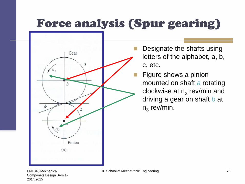
Force analysis (Spur gearing)
Designate the shafts using
letters of the alphabet, a, b,
c, etc.
Figure shows a pinion
mounted on shaft a rotating
clockwise at n2 rev/min and
driving a gear on shaft b at
n3 rev/min.
ENT345 Mechanical
Componets Design Sem 1-
2014/2015
Dr. School of Mechatronic Engineering 79
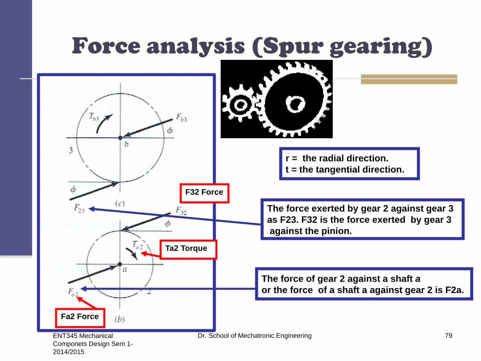
Force analysis (Spur gearing)
Fa2 Force
Ta2 Torque
F32 Force
r = the radial direction.
t = the tangential direction.
The force exerted by gear 2 against gear 3
as F23. F32 is the force exerted by gear 3
against the pinion.
The force of gear 2 against a shaft a
or the force of a shaft a against gear 2 is F2a.
ENT345 Mechanical
Componets Design Sem 1-
2014/2015
Dr. School of Mechatronic Engineering 80
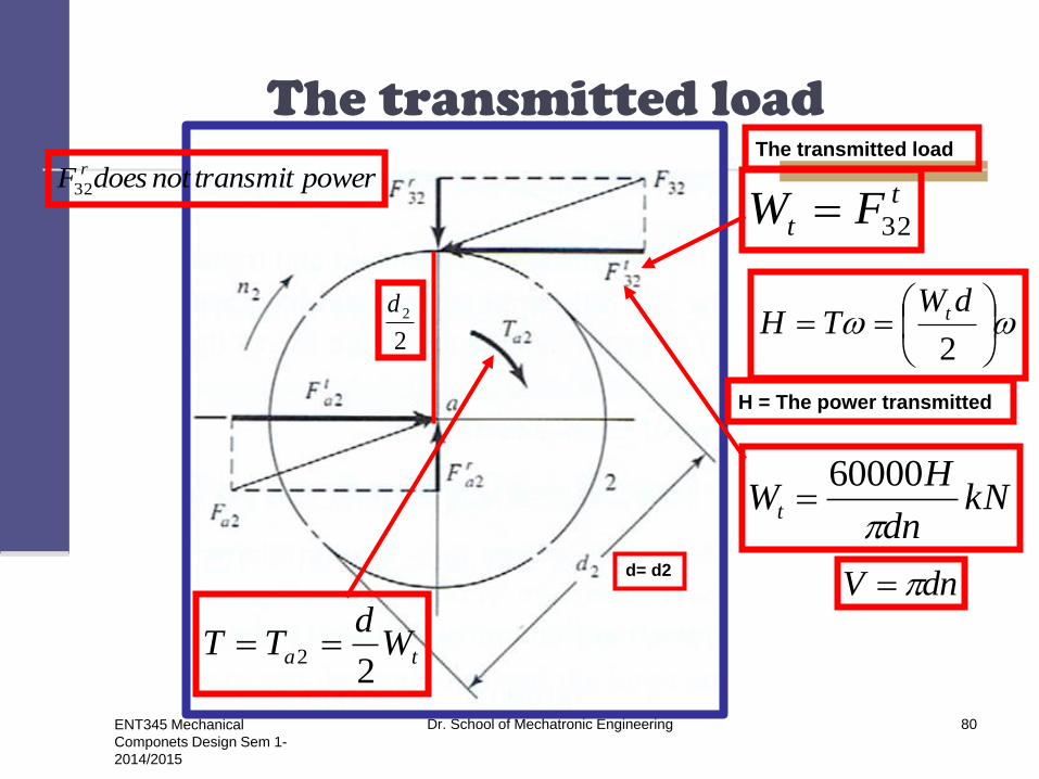
The transmitted load
t
t FW 32
The transmitted load
ta Wd
TT2
2
d= d2
2
dWTH t
H = The power transmitted
powertransmitnotdoesF r
32
2
2d
kNdn
HWt
60000
dnV

ENT345 Mechanical
Componets Design Sem 1-
2014/2015
Dr. School of Mechatronic Engineering 81
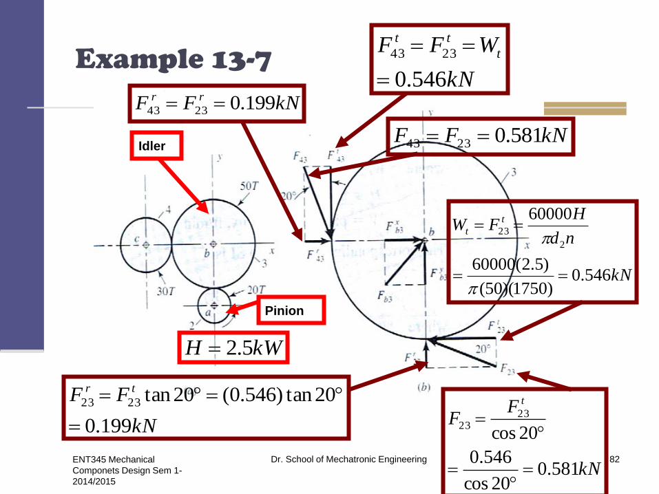
Example 13-7
Pinion 2 runs at 1750
rev/min and transmits
2.5 kW to idler gear 3.
The teeth are cut on the
20° full-depth system
and have a module of m
= 2.5 mm. Draw a free
body diagram of gear 3
and show all the forces
that act upon it.
Solution
The pitch diameter of gears 2
and 3 are
The transmitted load
mmmNd
mmmNd
125)5.2(50
50)5.2(20
33
22
kN
nd
HFW t
t
546.0
)1750)(50(
)5.2(60000
60000
2
23
ENT345 Mechanical
Componets Design Sem 1-
2014/2015
Dr. School of Mechatronic Engineering 82
Example 13-7
kN
nd
HFW t
t
546.0)1750)(50(
)5.2(60000
60000
2
23
kWH 5.2
Pinion
Idler
kN
FF tr
199.0
20tan)546.0(20tan2323
kN
FF
t
581.020cos
546.0
20cos
2323
kN
WFF t
tt
546.0
2343
kNFF rr 199.02343
kNFF 581.02343
ENT345 Mechanical
Componets Design Sem 1-
2014/2015
Dr. School of Mechatronic Engineering 83
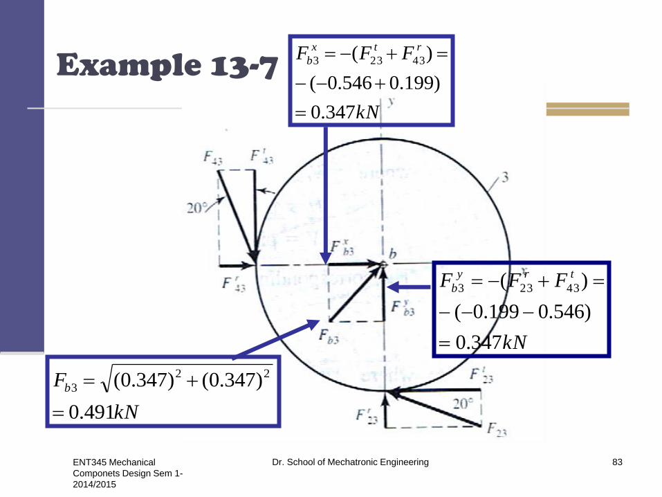
Example 13-7
kN
FFF rtx
b
347.0
)199.0546.0(
)( 43233
kN
FFF try
b
347.0
)546.0199.0(
)( 43233
kN
Fb
491.0
)347.0()347.0( 22
3

ENT345 Mechanical
Componets Design Sem 1-
2014/2015
Dr. School of Mechatronic Engineering 84
Force analysis-bevel gearing
av
tr
TW
costantr WW
sintanta WW
tantW
Wavr
ENT345 Mechanical
Componets Design Sem 1-
2014/2015
Dr. School of Mechatronic Engineering 85
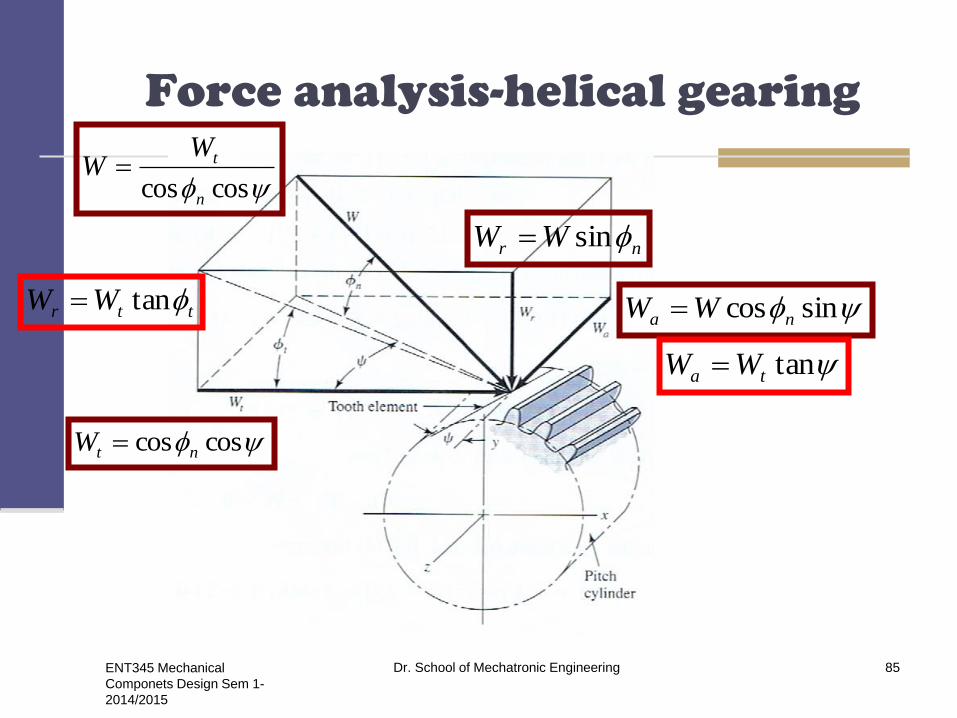
Force analysis-helical gearing
nr WW sin
sincos na WW
coscos ntW
ttr WW tan
tanta WW
coscos n
tWW

ENT345 Mechanical
Componets Design Sem 1-
2014/2015
Dr. School of Mechatronic Engineering 86
Force analysis-worm gearing
sincos n
x WW
n
y WW sin
n
coscos n
z WW
)cossin(cos fWW n
x
)sincos(cos fWW n
z

ENT345 Mechanical
Componets Design Sem 1-
2014/2015
Dr. School of Mechatronic Engineering 87
Velocity components in
worm gearing
cos
W
s
VV

ENT345 Mechanical
Componets Design Sem 1-
2014/2015
Dr. School of Mechatronic Engineering 88
ENT345 Mechanical
Componets Design Sem 1-
2014/2015
Dr. School of Mechatronic Engineering 89

Spur and Helical gears
Objectives
To analysis and design of spur and helical gears to
resist bending failure of the teeth as well as pitting
failure of tooth surface.
Failure by bending will occur when the significant
tooth stress equals or exceeds either the yield
strength or the bending endurance strength.
ENT345 Mechanical
Componets Design Sem 1-
2014/2015
Dr. School of Mechatronic Engineering 90
AGMA
The American Gear Manufacturers
Association (AGMA) has for many years
been the responsible authority for the
dissemination of knowledge pertaining to
the design analysis of gearing.
ENT345 Mechanical
Componets Design Sem 1-
2014/2015
Dr. School of Mechatronic Engineering 91
The Lewis Bending Equation
Wilfred Lewis introduced an equation for
estimating the bending stress in gear teeth in
which the tooth form entered into the
formula.
The equation, announced in 1892, still
remains the basis for most gear design
today.
ENT345 Mechanical
Componets Design Sem 1-
2014/2015
Dr. School of Mechatronic Engineering 92

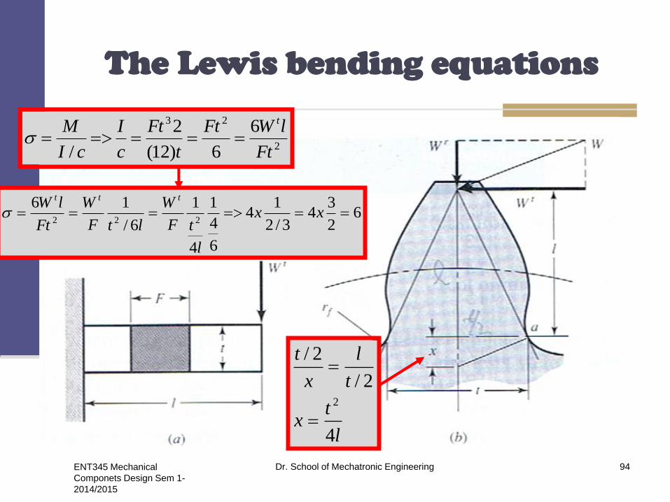
The Lewis Bending Equation
To derive the basic Lewis equation refer to Figure,
which shows a cantilever of cross-sectional
dimensions F and t, having a length l and a load
Wt, uniformly distributed across the face width F.
The section modulus: I/c = Ft2/6
The bending stress (σ ).
ENT345 Mechanical
Componets Design Sem 1-
2014/2015
Dr. School of Mechatronic Engineering 93
ENT345 Mechanical
Componets Design Sem 1-
2014/2015
Dr. School of Mechatronic Engineering 94
The Lewis bending equations
2
23 6
6)12(
2
/ Ft
lWFt
t
Ft
c
I
cI
M t
l
tx
t
l
x
t
4
2/
2/
2
62
34
3/2
14
6
4
1
4
1
6/
16222
xx
l
tF
W
ltF
W
Ft
lW ttt

ENT345 Mechanical
Componets Design Sem 1-
2014/2015
Dr. School of Mechatronic Engineering 95
The Lewis bending equations
Fpy
pW
p
xy
xpF
pW
t
t
3
2
3
2
3
2
,
xPY
FY
PW
yYp
P
t
y is The Lewis form factor
Y means that only the bending of the tooth is considered and
that the compression due to the radial component of the force is neglected.
Wr
Wt
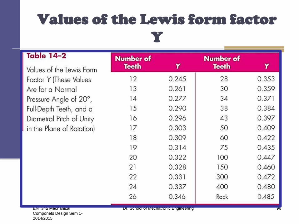
Values of the Lewis form factor
Y
ENT345 Mechanical
Componets Design Sem 1-
2014/2015
Dr. School of Mechatronic Engineering 96
Dynamic effects
When a pair of gears is driven at moderate or high
speed and noise is generated, it is certain that
dynamic effects are present.
If a pair of gears failed at 500 lbf tangential load at
zero velocity and at 250 lbf at velocity V1, then a
velocity factor, designated Kv, of 2 was specified
for the gears at velocity V1.
ENT345 Mechanical
Componets Design Sem 1-
2014/2015
Dr. School of Mechatronic Engineering 97
ENT345 Mechanical
Componets Design Sem 1-
2014/2015
Dr. School of Mechatronic Engineering 98
Dynamic effects
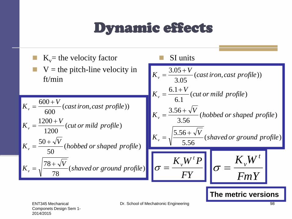
Kv= the velocity factor
V = the pitch-line velocity in
ft/min
SI units
)(78
78
)(50
50
)(1200
1200
)),(600
600
profilegroundorshavedV
K
profileshapedorhobbedV
K
profilemildorcutV
K
profilecastironcastV
K
v
v
v
v
)(56.5
56.5
)(56.3
56.3
)(1.6
1.6
)),(05.3
05.3
profilegroundorshavedV
K
profileshapedorhobbedV
K
profilemildorcutV
K
profilecastironcastV
K
v
v
v
v
FY
PWK t
vFmY
WK t
v
The metric versions

Example 14-1
A stock spur gear is available having a module of
3mm, a 38 mm face width, 16 teeth, and a
pressure angle of 20° with full-depth teeth. The
material is AISI 1020 steel in as-rolled condition.
Use a design factor of nd = 3 to rate the power
output of the gear corresponding to a speed of 20
rev/s and moderate applications.
ENT345 Mechanical
Componets Design Sem 1-
2014/2015
Dr. School of Mechatronic Engineering 99

Example 14-1
Solution
The term moderate applications seems to imply
that the gear can be rated by using the yield
strength as a criterion of failure. From Table A-18,
Sut = 380 MPa and Sy =210MPa.
A design factor of 3 means that the allowable
bending stress is 210/3 =70 MPa.
The pitch diameter is Nm = 16 (3) = 48 mm.
The pitch-line velocity is V=πdn=π(0.049)
20=3.02m/s
ENT345 Mechanical
Componets Design Sem 1-
2014/2015
Dr. School of Mechatronic Engineering 100
Example 14-1
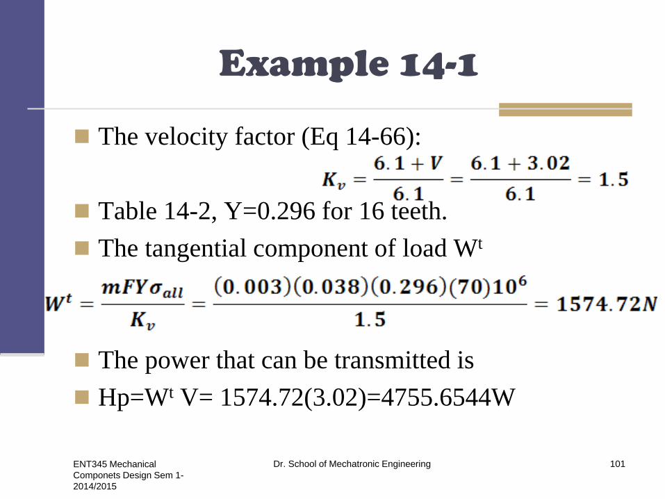
The velocity factor (Eq 14-66):
Table 14-2, Y=0.296 for 16 teeth.
The tangential component of load Wt
The power that can be transmitted is
Hp=Wt V= 1574.72(3.02)=4755.6544W
ENT345 Mechanical
Componets Design Sem 1-
2014/2015
Dr. School of Mechatronic Engineering 101

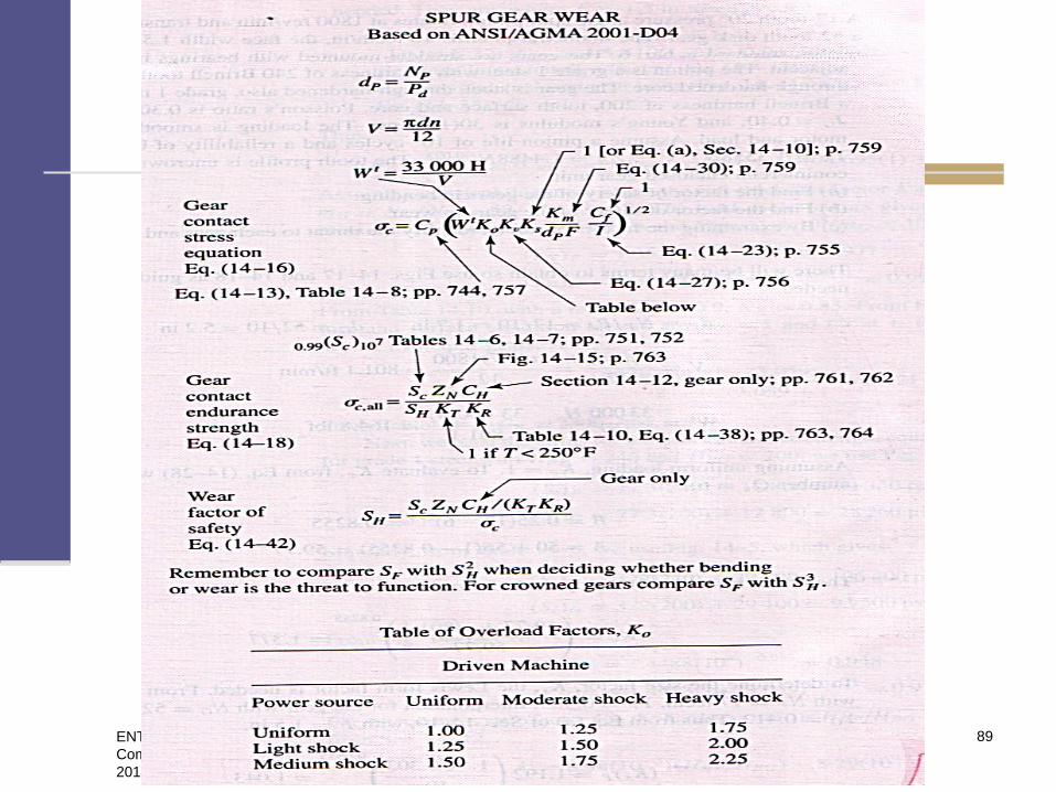
Surface durability
Wear is the failure of the surfaces of gear
teeth.
Pitting is a surface fatigue failure due to
many repetitions of high contact stresses.
Scoring is a lubrication failure, and
abrasion, which is wear due to the presence
of foreign material.
ENT345 Mechanical
Componets Design Sem 1-
2014/2015
Dr. School of Mechatronic Engineering 102

Surface durability
To obtain an expression for the surface-contact
stress, we shall employ the Hertz theory. The
contact stress between two cylinders may
computed from the equation;
pmax =largest surface pressure.
F= force pressing the two cylinders together.
L = length of cylinders.
ENT345 Mechanical
Componets Design Sem 1-
2014/2015
Dr. School of Mechatronic Engineering 103
Surface durability
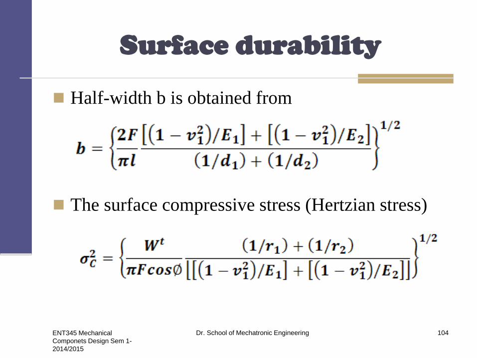
Half-width b is obtained from
The surface compressive stress (Hertzian stress)
ENT345 Mechanical
Componets Design Sem 1-
2014/2015
Dr. School of Mechatronic Engineering 104

Surface durability
The radii of curvature of the tooth profiles at the
pitch point are
An elastic coefficient Cp
ENT345 Mechanical
Componets Design Sem 1-
2014/2015
Dr. School of Mechatronic Engineering 105

AGMA strength equations
Two fundamental stress equations are used in the
AGMA methodology, one for bending stress and
another for pitting resistance (contact stress).
In AGMSA terminology, these are called stress
numbers, as contrasted with actual applied stress
(σ).
ENT345 Mechanical
Componets Design Sem 1-
2014/2015
Dr. School of Mechatronic Engineering 106

AGMA strength equations
Pitting resistance
ENT345 Mechanical
Componets Design Sem 1-
2014/2015
Dr. School of Mechatronic Engineering 107
AGMA strength equations
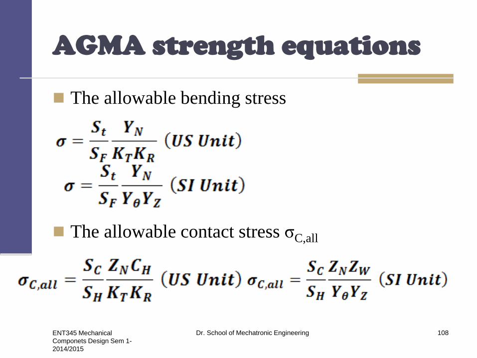
The allowable bending stress
The allowable contact stress σC,all
ENT345 Mechanical
Componets Design Sem 1-
2014/2015
Dr. School of Mechatronic Engineering 108
Bevel gears
Bevel gears may classified :
Spiral bevel gears
Zerol bevel gears
Hypoid gears
Spiroid gears
ENT345 Mechanical
Componets Design Sem 1-
2014/2015
Dr. School of Mechatronic Engineering 109

Straight bevel gears
ENT345 Mechanical
Componets Design Sem 1-
2014/2015
Dr. School of Mechatronic Engineering 110

ENT345 Mechanical
Componets Design Sem 1-
2014/2015
Dr. School of Mechatronic Engineering 111
Straight bevel gear
The pitch angles are defined
by the pitch cones meeting at
the apex. They are related to
the tooth numbers as follows;
The virtual number of teeth
(N’) and p is the circular
pitch.
P
G
G
P
N
N
N
N
tan
tan
p
rN b2
'

Spiral bevel gears
ENT345 Mechanical
Componets Design Sem 1-
2014/2015
Dr. School of Mechatronic Engineering 112

Zerol bevel gears
ENT345 Mechanical
Componets Design Sem 1-
2014/2015
Dr. School of Mechatronic Engineering 113
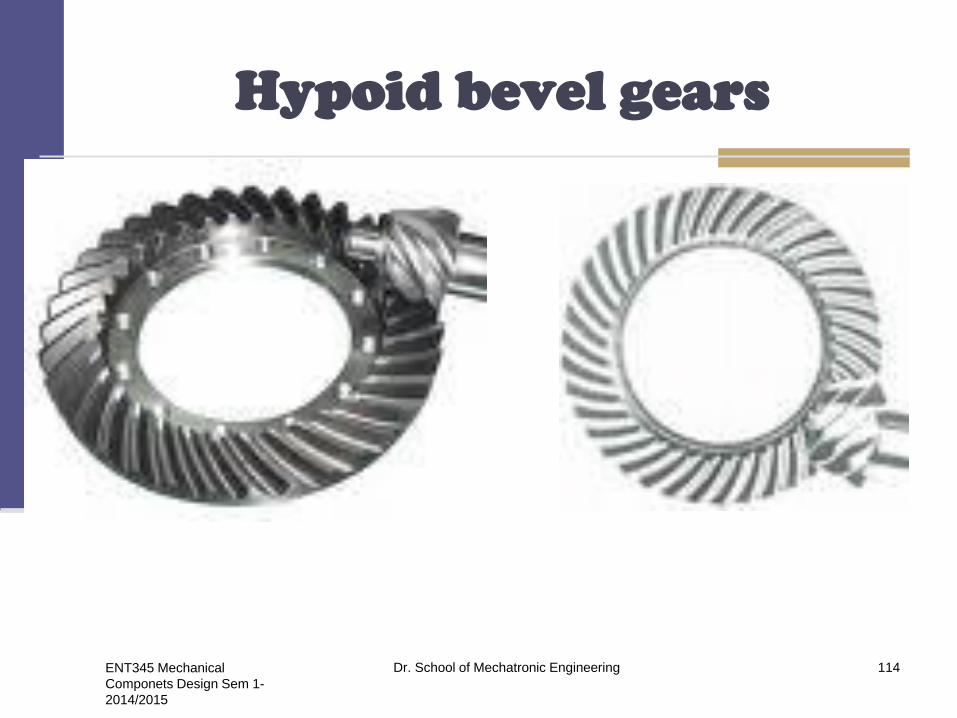
Hypoid bevel gears
ENT345 Mechanical
Componets Design Sem 1-
2014/2015
Dr. School of Mechatronic Engineering 114
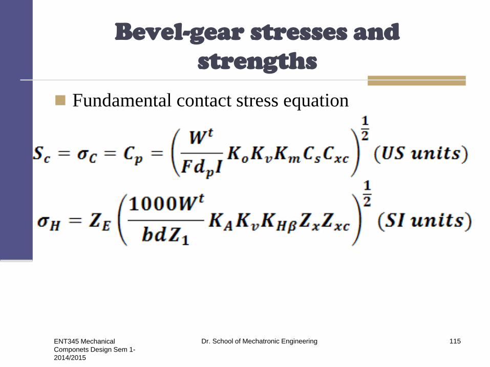
Bevel-gear stresses and
strengths
Fundamental contact stress equation
ENT345 Mechanical
Componets Design Sem 1-
2014/2015
Dr. School of Mechatronic Engineering 115

Bevel-gear stresses and
strengths
Permissible contact stress number
(strength) equation.
Bending Stress.
Permissible bending stress
equation.
ENT345 Mechanical
Componets Design Sem 1-
2014/2015
Dr. School of Mechatronic Engineering 116

AGMA equation factors
Overload factor Ko (KA)
Safety factors SH and SF
Dynamic factor Kv.
Size factor for pitting resistance Cs (Zx).
Size factor for bending Ks (Yx)
Dynamic factor Kv.
Size factor for pitting resistance Cs (Zx)
Size factor for bending Ks (Yx)
Load distribution factor Km(KHβ)
ENT345 Mechanical
Componets Design Sem 1-
2014/2015
Dr. School of Mechatronic Engineering 117
AGMA equation factors
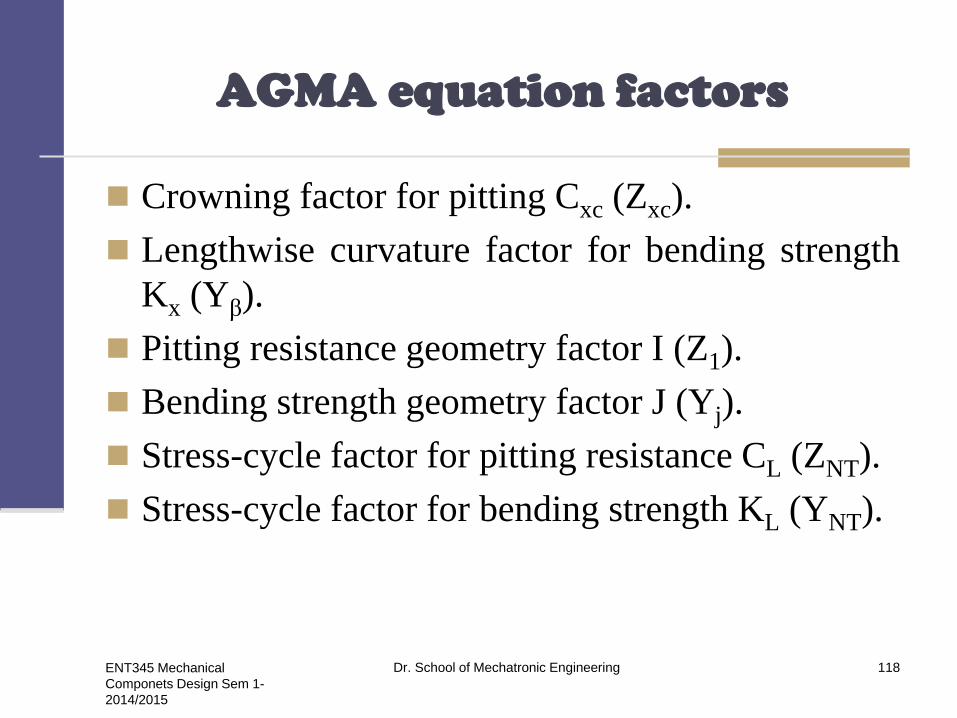
Crowning factor for pitting Cxc (Zxc).
Lengthwise curvature factor for bending strength
Kx (Yβ).
Pitting resistance geometry factor I (Z1).
Bending strength geometry factor J (Yj).
Stress-cycle factor for pitting resistance CL (ZNT).
Stress-cycle factor for bending strength KL (YNT).
ENT345 Mechanical
Componets Design Sem 1-
2014/2015
Dr. School of Mechatronic Engineering 118

AGMA equation factors
Hardness-ratio factor CH (ZW).
Temperature factor KT (Kθ).
Reliability factors CR (ZZ) and KR (YZ).
Elastic coefficient for pitting resistance Cp (ZE).
Allowable contact stress.
Allowable bending stress numbers
Reversed Loading.
ENT345 Mechanical
Componets Design Sem 1-
2014/2015
Dr. School of Mechatronic Engineering 119
Straight bevel gear analysis
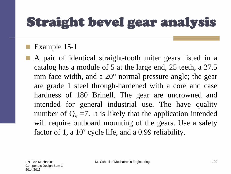
Example 15-1
A pair of identical straight-tooth miter gears listed in a
catalog has a module of 5 at the large end, 25 teeth, a 27.5
mm face width, and a 20° normal pressure angle; the gear
are grade 1 steel through-hardened with a core and case
hardness of 180 Brinell. The gear are uncrowned and
intended for general industrial use. The have quality
number of Qv =7. It is likely that the application intended
will require outboard mounting of the gears. Use a safety
factor of 1, a 107 cycle life, and a 0.99 reliability.
ENT345 Mechanical
Componets Design Sem 1-
2014/2015
Dr. School of Mechatronic Engineering 120

Straight bevel gear analysis
a) For a speed of 600 rev/min, find the power rating of this
gearset based on AGMA bending strength.
H=Wt Vet
a) For the same conditions as in part (a) find the power
rating of this gearset based on AGMA wear strength.
H=Wt Vet (Wear)
a) For reliability of 0.995 a gear life of 109 revolutions, and a
safety factor of SF = SH =1.5, find the power rating for
this gearset using AGMA strengths.
H=Wt Vet (life goal 109 cycles)
ENT345 Mechanical
Componets Design Sem 1-
2014/2015
Dr. School of Mechatronic Engineering 121
Straight bevel gear analysis
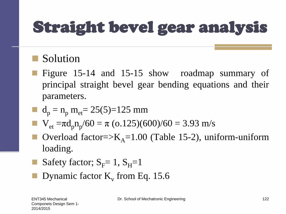
Solution
Figure 15-14 and 15-15 show roadmap summary of
principal straight bevel gear bending equations and their
parameters.
dp = np met= 25(5)=125 mm
Vet =πdpnp/60 = π (o.125)(600)/60 = 3.93 m/s
Overload factor=>KA=1.00 (Table 15-2), uniform-uniform
loading.
Safety factor; SF= 1, SH=1
Dynamic factor Kv from Eq. 15.6
ENT345 Mechanical
Componets Design Sem 1-
2014/2015
Dr. School of Mechatronic Engineering 122

Straight bevel gear analysis
B=0.25 (12-7)2/7 = 0.731
A=50+56(1-0.731)=65.06
Vet max =[A+(Qv-3)]2/200
=[65.06+(7-3)]2/200=23.8m/s
Vet<Vetmax, 3.93<23.8m/s
Kv is valid (Eq 15-10)
Yx =0.487+0.008 339met, 1.6 ≤ met ≤ 50 mm
Yx =0.487+0.008 339 (5) = 0.528
ENT345 Mechanical
Componets Design Sem 1-
2014/2015
Dr. School of Mechatronic Engineering 123

Straight bevel gear analysis
Eq 15-11, Kmb =1.25 and KHB = 1.25+5.6(10-6)(27.5)2=1.254
Eq 15-13, YB =1. Eq 15-6, Z1 =0.065; from 15-7, Yj =0.216,
JG =0.216.
Eq 15-15, YNT = 1.683 (107) -0.0323 =0.99996 = 1
From Eq (15-14)
ZNT=3.4822(107) -0.0602 =1.32
Since HB1/HB2 = 1, then from Fig. 15-10, Zw=1 . From Eq.
15-13 and 15-18, YB =1 and Kθ =1, respectively.
Eq 15-20, Yz=0.70-0.15log(1-0.99)=1, Zz =√YZ = √1=1
ENT345 Mechanical
Componets Design Sem 1-
2014/2015
Dr. School of Mechatronic Engineering 124

Straight bevel gear analysis
a) Bending: From Eq. 15-23
σFilm = 0.3 (180)+14.48 = 68.48 Mpa
Eq 15-3
ENT345 Mechanical
Componets Design Sem 1-
2014/2015
Dr. School of Mechatronic Engineering 125

Straight bevel gear analysis
0.029 Wt = 64.48
Wt =2223 N
H = Wt Vet = 2223 (3.93) = 8736 W
b) Wear
From Fig 15-12, σH lim=2.35(180)+(162.89)= 585.9 Mpa
From Eq. 15-12
ENT345 Mechanical
Componets Design Sem 1-
2014/2015
Dr. School of Mechatronic Engineering 126

Straight bevel gear analysis
ZE= 190√N/mm2
ZX =0.004(92)(27.5)+(0.4375)=0.573
From Eq (15-12), ZXC =2, substituting in Eq (15-1):
ENT345 Mechanical
Componets Design Sem 1-
2014/2015
Dr. School of Mechatronic Engineering 127

Straight bevel gear analysis
Equating σH and σHP gives
17.37√Wt = 773.4
Wt= 1982
H = Wt Vet = 1982 (3.93) = 7789 W
Rated power for the gearset is
H= min (8736, 7789) =7789 Watt
C) Life goal 109 cycles, R = 0.995, SF = SH = 1.5 and from
Eq 15-15
YNT=1.683 (109) -0.0323 =0.8618
ENT345 Mechanical
Componets Design Sem 1-
2014/2015
Dr. School of Mechatronic Engineering 128
Straight bevel gear analysis
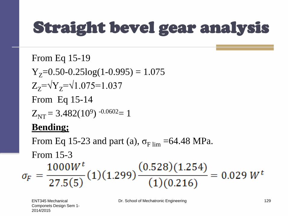
From Eq 15-19
YZ=0.50-0.25log(1-0.995) = 1.075
ZZ=√YZ=√1.075=1.037
From Eq 15-14
ZNT = 3.482(109) -0.0602= 1
Bending;
From Eq 15-23 and part (a), σF lim =64.48 MPa.
From 15-3
ENT345 Mechanical
Componets Design Sem 1-
2014/2015
Dr. School of Mechatronic Engineering 129

Straight bevel gear analysis
From Eq 15-14
Equating σF to σFP
0.029 Wt = 34.5 => Wt = 1190 N
H= 1190 (3.73) = 4438.7 Watt
Wear
From Eq 15-22 and part (b), σ H lim =585.9 MPa
ENT345 Mechanical
Componets Design Sem 1-
2014/2015
Dr. School of Mechatronic Engineering 130

Straight bevel gear analysis
From Eq 15-2
Substituting into Eq 15-1 gives part (b), σ H lim =17.37√Wt
Equating σH to (σH)P
376.7 = 17.37 √ Wt => Wt =470 N
The wear power is
H = 470 (3.73) = 1753 W
H = min (4438.7, 1753) = 1753 Watt
ENT345 Mechanical
Componets Design Sem 1-
2014/2015
Dr. School of Mechatronic Engineering 131

Design of a straight bevel gear mesh
A useful decision set for straight-bevel gear design is
A priori decisions
Function
Design factor
Tooth system
Tooth count
Design variables
Pitch and face width
Quality number
Gear material, core and case hardness
Pinion material, core and case hardness.
ENT345 Mechanical
Componets Design Sem 1-
2014/2015
Dr. School of Mechatronic Engineering 132

Worm gear analysis
Example 15-3
A single-thread steel worm rotates at 1800 rev/min,
meshing with a 24-tooth worm gear transmitting 3 hp to
the output shaft. The worm pitch diameter is 3 in and the
tangential diametral pitch of the gear is 4 teeth/in. The
normal pressure angle is 14.5°. The ambient temperature
is 70°F. The application factor is 1.25 and the design
factor is 1; gear face width is 2 in, lateral case area 600
in2, and the gear is chill-cast bronze.
ENT345 Mechanical
Componets Design Sem 1-
2014/2015
Dr. School of Mechatronic Engineering 133

Worm gear analysis
a) Find the geometry
b) Find the transmitted gear forces and the mesh efficiency.
c) Is the mesh sufficient to handle the loading?
d) Estimate the lubricant sump temperature.
Solution
a) Find the geometry
mG=NG/NW=24/1 = 24
Gear : D=NG/Pt = 24/4 = 6.000 in
Worm : d= 3.000 in
ENT345 Mechanical
Componets Design Sem 1-
2014/2015
Dr. School of Mechatronic Engineering 134

Worm gear analysis
The axial circular pitch px is px =π/pt =π/4 = 0.7854 in
C=(3+6)/2 = 4.5 in
Eq 15-39 , a = px/π = 0.7854/π= 0.250 in
Eq 15-40, b=0.3683 px = 0.3683 (0.7854) = 0.289 in
Eq 15-41, ht = 0.6866 px = 0.6866 (0.7854)=0.539 in
Eq 15-42, do=3+2(0.250)=3.500 in
Eq 15-43, dr = 3-2(0.289) = 2.422 in
Eq 15-44, Dt=6+2(0.250) = 6.500 in
Eq 15-45, Dr = 6-2(0.289) = 5.422 in
Eq 15-46, c = 0.289-0.250= 0.039 in
ENT345 Mechanical
Componets Design Sem 1-
2014/2015
Dr. School of Mechatronic Engineering 135

Worm gear analysis
Eq 15-47, (FW)max =2√2(6)(0.250) = 3.464 in
The tangential speeds of the worm, VW, and gear, VG, are respectively.
VW=π(3)1800/12 =1414 ft/min.
VG= π(6)(1800)/24 = 117.8 ft/min
2
The lead of the worm, fro Eq 13-27, is L=pxNW =0.7854(1)=0.7854 in.
The lead angle λ from Eq 13-28 is λ= tan-1 L/πd = tan-1 0.7854/π(3)
=4.764°
The normal diametral pitch for a gear is the same as for a helical gear,
which from Eq 13-18 with Ψ =λ is…
ENT345 Mechanical
Componets Design Sem 1-
2014/2015
Dr. School of Mechatronic Engineering 136

Worm gear analysis
The sliding velocity, from Eq 15-62 is
ENT345 Mechanical
Componets Design Sem 1-
2014/2015
Dr. School of Mechatronic Engineering 137

Worm gear analysis
b) The coefficient of friction, from Eq 15-38 is
F=0.103 exp[-0.110(1419) 0.450]+0.012 = 0.0178
The efficiency e, from Eq 13-46, is
The designer used nd =1, Ka = 1.25 and an output horsepower of
Ho = 3 hp. The gear tangential force component WtG, from Eq
15-58;
ENT345 Mechanical
Componets Design Sem 1-
2014/2015
Dr. School of Mechatronic Engineering 138

Worm gear analysis
The tangential force on the worm is given by Eq 15-57
ENT345 Mechanical
Componets Design Sem 1-
2014/2015
Dr. School of Mechatronic Engineering 139
ENT345 Mechanical
Componets Design Sem 1-
2014/2015
Dr. School of Mechatronic Engineering 140
THANK YOU