lecture no. 7 -strain energy- - al-mustansiriya...
TRANSCRIPT

Strain Energy
1
Lecture No. 7
-STRAIN ENERGY-
7-1 Introduction: -
Strain energy is as the energy which is stored within a material when
work has been done on the material. Here it is assumed that the material remains
elastic whilst work is done on it so that all the energy is recoverable and no
permanent deformation occurs due to yielding of the material,
Strain energy U = work done
Thus for a gradually applied load the work done in straining the material
will be given by the shaded area under the load-extension graph of Fig.
U =
P δ
Figure 7.1: - Work done by a gradually applied load.
The unshaded area above the line OB of Fig. 7.1 is called the
complementary energy, a quantity which is utilized in some advanced energy
methods of solution and is not considered within the terms of reference of this
text.

Strain Energy
2
7-2 Strain energy - tension or compression: -
a- Neglecting the weight of the bar: -
Consider a small element of a bar, length ds, shown in Fig. 7.1. If a graph
is drawn of load against elastic extension the shaded area under the graph gives
the work done and hence the strain energy,
U =
P δ ….(1)
But young modulus E=
…. (2)
Now, substituting eqn. (2) in (1)
For bar element,
Total strain energy for a bar of length L, ∫
U=
….7.1
b- Including the weight of the bar: -
Consider now a bar of length L mounted vertically, as shown in Fig. 7.2.
At any section A B the total load on the section will be the external load P
together with the weight of the bar material below AB.
Figure 7.2: - Direct load - tension or compression.
Strain Energy
3
Load on section A B = P ± ρgAs
The positive sign being used when P is tensile and the negative sign when
P is compressive. Thus, for a tensile force P the extension of the element ds is
given by the definition of Young's modulus E to be
But work done =
load x extension
So, the total strain energy or work done is,
=∫
∫
∫
U
….7.2
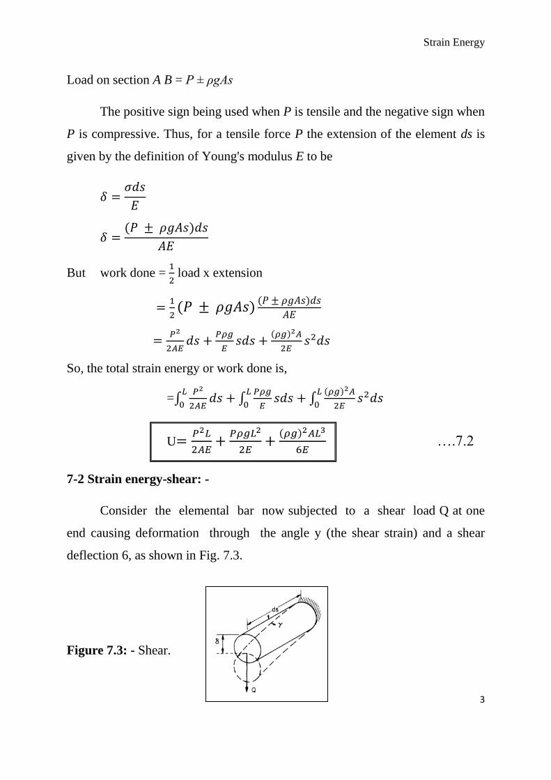
7-2 Strain energy-shear: -
Consider the elemental bar now subjected to a shear load Q at one
end causing deformation through the angle y (the shear strain) and a shear
deflection 6, as shown in Fig. 7.3.
Figure 7.3: - Shear.

Strain Energy
4
Strain energy U = work done =
…. (1)
But modulus of rigidity
…. (2)
Substitute eqn. (2) in (1),
Shear strain energy
:. Total strain energy resulting from shear ∫
7-3 Strain energy –bending: -
Let the element now be subjected to a constant bending moment M
causing it to bend into an arc of radius R and subtending an angle dϴ at the
center (Fig. 7.4). The beam will also have moved through an angle dϴ.
Figure 7.4: - Bending.
Strain energy = work done =
moment x angle turned through (in radians)
Strain Energy
5
…. (1)
But
…. (2)
Substitute eqn. (2) in (1),
= Strain energy ؞
Total strain energy resulting from bending, ∫
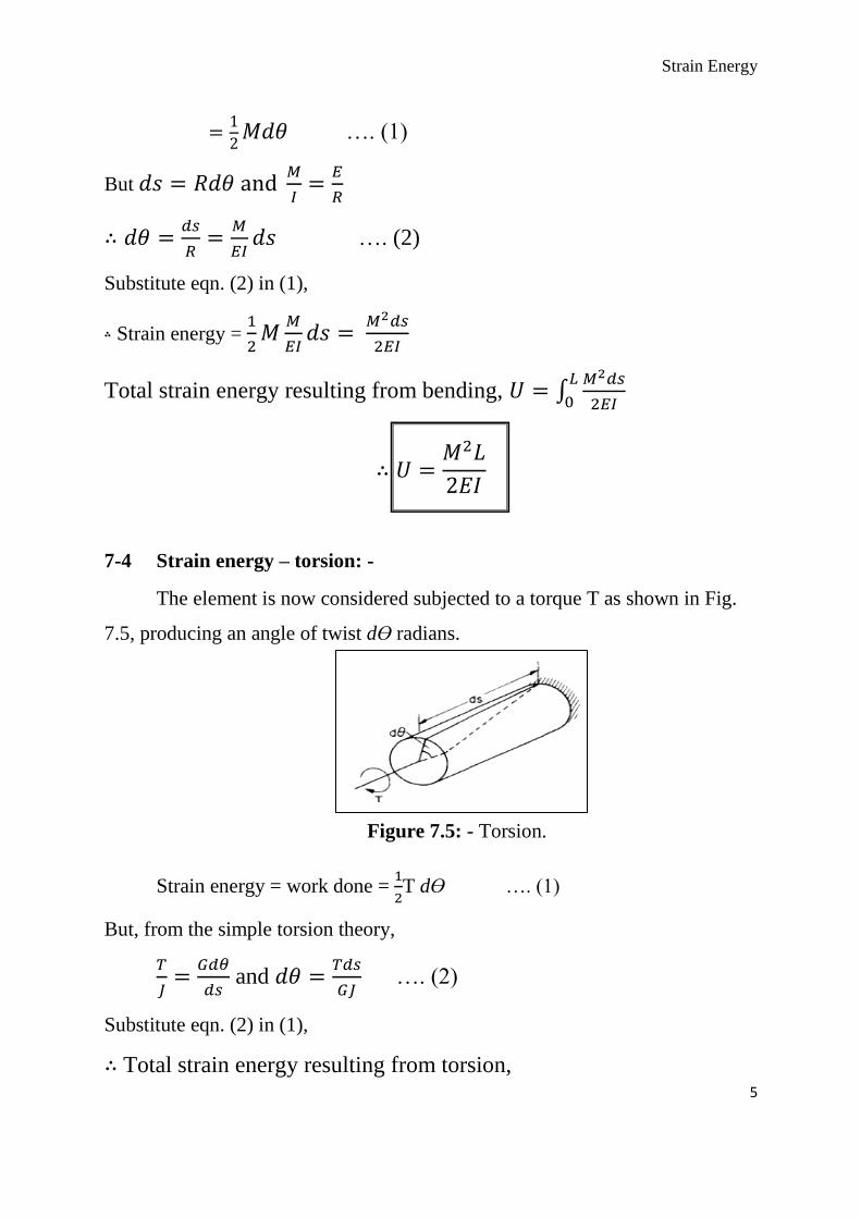
7-4 Strain energy – torsion: -
The element is now considered subjected to a torque T as shown in Fig.
7.5, producing an angle of twist dϴ radians.
Figure 7.5: - Torsion.
Strain energy = work done =
T dϴ …. (1)
But, from the simple torsion theory,
and
…. (2)
Substitute eqn. (2) in (1),
Total strain energy resulting from torsion,

Strain Energy
6
∫
Note: - It should be noted that in the four types of loading case considered
above the strain energy expressions are all identical in form,
7-5 Castigliano’s first theorem assumption for deflection: -
If the total strain energy of a body or framework is expressed in terms of
the external loads and is partially differentiated with respect to one of the loads
the result is the deflection of the point of application of that load and in the
direction of that load,
i.e.
,
and
Where a, b and c are deflections of a beam under loads Pa, Pb and Pc etc. as
shown in fig 7.6.
Figure 7.6: - Any beam or structure subjected to a system of applied
concentrated loads P a , Pb, Pc , . . . Pn,, etc.
In most beam applications the strain energy, and hence the deflection,
resulting from end loads and shear forces are taken to be negligible in
comparison with the strain energy resulting from bending (torsion not
normally being present),
Strain Energy
7
∫
∫
∫
7-6 Application of Castigliano’s theorem to angular movements:
If the total strain energy, expressed in terms of the external
moments, be partially differentiated with respect to one of the moments, the
result is the angular deflection (in radians) of the point of application of that
moment and in its direction,
∫
Example 7-1: -Determine the diameter of an aluminum shaft which is
designed to store the same amount of strain energy per unit volume as a 50mm
diameter steel shaft of the same length. Both shafts are subjected to equal
compressive axial loads. What will be the ratio of the stresses set up in the two
shafts?
Esteel = 200 GN/m2; Ealuminum = 67 GN/m
2.
Sol.
Strain energy per unit volume
but
Strain energy per unit volume
Since the strain energy/unit volume in the two shafts is equal,

Strain Energy
8
approximately.
√
(
) (
) but Ps=PA=P and
(
)
(
)
√
√
Example 7-2: - Two shafts are of the same material, length and weight.
One is solid and 100 mm diameter, the other is hollow. If the hollow shaft is to
store 25 % more energy than the solid shaft when transmitting torque, what
must be its internal and external diameters? Assume the same maximum shear
stress applies to both shafts.
Sol.
Let A be the solid shaft and B the hollow shaft. If they are the same
weight and the same material their volume must be equal.
(
)
(
) …. (1)
Now for the same maximum shear stress,
.… (2)
But the strain energy of B = 1.25 x strain energy of A.

Strain Energy
9
…. (3)
Now substitute eqn. (2) in (3),
Substitute in eqn. (1)
Example 7-3: - Using Castigliano's first theorem, obtain the expressions for (a)
the deflection under a single concentrated load applied to a simply supported
beam as shown in Figure below, (b) the deflection at the center of a simply
supported beam carrying a uniformly distributed load.
a-

Strain Energy
10
b-

Strain Energy
11
Example 7-4: - Derive the equation for the slope at the free end of a cantilever
carrying a uniformly distributed load over its full length.
Sol.
Strain Energy
12
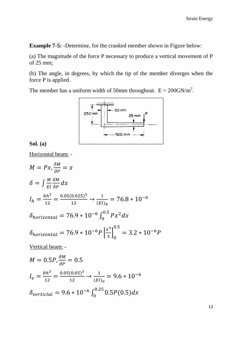
Example 7-5: -Determine, for the cranked member shown in Figure below:
(a) The magnitude of the force P necessary to produce a vertical movement of P
of 25 mm;
(b) The angle, in degrees, by which the tip of the member diverges when the
force P is applied.
The member has a uniform width of 50mm throughout. E = 200GN/m2.
Sol. (a)
Horizontal beam: -
∫
∫
*
+
Vertical beam: -
∫

Strain Energy
13
[ ]
P = 6.58kN.
Sol. (b)
∫
Horizontal beam: -
∫
*
+
when
But P=6.58kN.
Vertical beam: -
∫
[ ] but and P=6.58kN.
7.896* rad.
7.896* =0.071 rad=4.1°

Strain Energy
14
H.W. A semicircular frame of flexural rigidity (EI) is built in at A and carries
a vertical load W at B as shown in Figure (1). Calculate the magnitude of
horizontal deflection at B.
Figure (1)
..…………………….End…………………………