lecture #4 power dividers and directional couplers shoubra...introduction •power dividers and...
TRANSCRIPT

Lecture #4 Power Dividers and Directional Couplers
Instructor: Dr. Ahmad El-Banna
Benha University Faculty of Engineering at Shoubra
No
vem
ber
2014
Post-Graduate ECE-601 Active Circuits
© A
hmad
El-B
anna

Agenda
Introduction
Basic Properties of Dividers and Couplers
Types of Dividers and Couplers 2
ECE-
601
, Lec
#4 , N
ov 2
014
© A
hmad
El-B
anna

INTRODUCTION 3
ECE-
601
, Lec
#4 , N
ov 2
014
© A
hmad
El-B
anna
Introduction
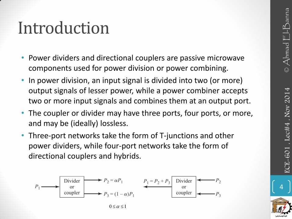
• Power dividers and directional couplers are passive microwave components used for power division or power combining.
• In power division, an input signal is divided into two (or more) output signals of lesser power, while a power combiner accepts two or more input signals and combines them at an output port.
• The coupler or divider may have three ports, four ports, or more, and may be (ideally) lossless.
• Three-port networks take the form of T-junctions and other power dividers, while four-port networks take the form of directional couplers and hybrids.
4
ECE-
601
, Lec
#4 , N
ov 2
014
© A
hmad
El-B
anna
Introduction..
• Power dividers usually provide in-phase output signals with an equal power division ratio (3 dB), but unequal power division ratios are also possible.
• Directional couplers can be designed for arbitrary power division, while hybrid junctions usually have equal power division. Hybrid junctions have either a 90◦ or a 180◦ phase shift between the output ports.
• Applications
• Dividing (combining) a transmitter (receiver) signal to many antennas.
• Separating forward and reverse propagating waves (can also use for a sort of matching).
• Signal combining for a mixer.
5
ECE-
601
, Lec
#4 , N
ov 2
014
© A
hmad
El-B
anna

BASIC PROPERTIES OF DIVIDERS AND COUPLERS
6
ECE-
601
, Lec
#4 , N
ov 2
014
© A
hmad
El-B
anna
Three-Port Networks (T-Junctions)
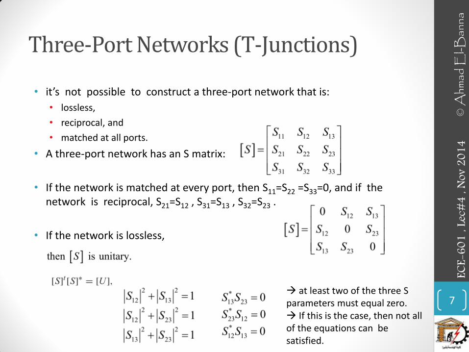
• it’s not possible to construct a three-port network that is:
• lossless,
• reciprocal, and
• matched at all ports.
• A three-port network has an S matrix:
• If the network is matched at every port, then S11=S22 =S33=0, and if the network is reciprocal, S21=S12 , S31=S13 , S32=S23 .
• If the network is lossless,
7
ECE-
601
, Lec
#4 , N
ov 2
014
© A
hmad
El-B
anna
at least two of the three S parameters must equal zero. If this is the case, then not all of the equations can be satisfied.

Three-Port Networks (T-Junctions)..
• Then a three-port network cannot be lossless, reciprocal, and matched at all ports. However, one can realize such a network if any of these three constraints is loosened.
8
ECE-
601
, Lec
#4 , N
ov 2
014
© A
hmad
El-B
anna
Examples: 1. Nonreciprocal three-port: In this case, a lossless three-port that is matched at all ports can be realized. It is called a circulator. 2. Match only two of the three ports. Assume ports 1 and 2 are matched.
3. Lossy network. All ports can be simultaneously matched and the network reciprocal.

Four-Port Networks (Directional Couplers)
• Unlike three-ports, it is possible to make a lossless, matched, and reciprocal four-port network. These are called directional couplers.
• The S matrix of a reciprocal and matched four-port has the form:
• There are two commonly used realizations of directional couplers:
• 1-The Symmetrical Coupler. The S matrix for this device is
• It’s called Quadrature (90°) Hybrid Coupler 9
ECE-
601
, Lec
#4 , N
ov 2
014
© A
hmad
El-B
anna

Four-Port Networks (Directional Couplers)
• 2. The Asymmetrical Coupler. The S matrix for this device is
• The network is matched, reciprocal and lossless.
• It’s called 180° Hybrid Coupler
10
ECE-
601
, Lec
#4 , N
ov 2
014
© A
hmad
El-B
anna

TYPES OF DIVIDERS AND COUPLERS 11
ECE-
601
, Lec
#4 , N
ov 2
014
© A
hmad
El-B
anna
Types
• The T-Junction Power Divider
• The Wilkinson Power Divider
• Waveguide Directional Couplers
• The Quadrature (90◦) Hybrid
• Coupled Line Directional Couplers
• The Lange Coupler
• The 180◦ Hybrid
12
ECE-
601
, Lec
#4 , N
ov 2
014
© A
hmad
El-B
anna

Directional Couplers
• The arrows indicate the assumed directions of time average power flow.
• The performance of directional couplers is characterized by the following values. For these definitions, port 1 is assumed the input, ports 2 and 3 the outputs, and port 4 is the isolated port.
13
ECE-
601
, Lec
#4 , N
ov 2
014
© A
hmad
El-B
anna

Hybrid Couplers
• Hybrid couplers are special cases of directional couplers, where the coupling factor is 3 dB, which implies that α = β = 1/√2.
• There are two types of hybrids.
• The quadrature hybrid has a 90◦ phase shift between ports 2 and 3 (θ = φ = π/2) when fed at port 1, and is an example of a symmetric coupler.
• The magic-T hybrid and the rat-race (ring) hybrid have a 180◦ phase difference between ports 2 and 3 when fed at port 4, and are examples of an antisymmetric coupler.
14
ECE-
601
, Lec
#4 , N
ov 2
014
© A
hmad
El-B
anna

Examples
15
ECE-
601
, Lec
#4 , N
ov 2
014
© A
hmad
El-B
anna
THE T-JUNCTION POWER DIVIDER
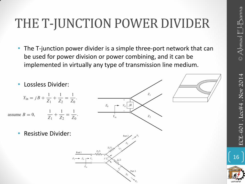
• The T-junction power divider is a simple three-port network that can be used for power division or power combining, and it can be implemented in virtually any type of transmission line medium.
• Lossless Divider:
• Resistive Divider:
16
ECE-
601
, Lec
#4 , N
ov 2
014
© A
hmad
El-B
anna

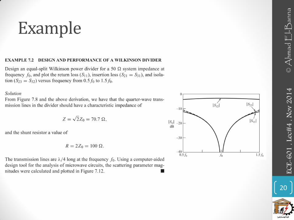
Example
17
ECE-
601
, Lec
#4 , N
ov 2
014
© A
hmad
El-B
anna

THE WILKINSON POWER DIVIDER
• This is a popular power divider because it is easy to construct and has some extremely useful properties:
• Matched at all ports,
• Large isolation between output ports,
• Reciprocal,
• Lossless when output ports are matched.
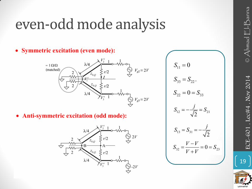
• There is much symmetry in this circuit that can be exploited to make the S parameter calculations easier.
• Specifically, we will excite this circuit in two very special configurations (symmetrically and anti-symmetrically), then add these two solutions for the total solution.
• This mathematical process is called an “even-odd mode analysis.” It is a technique used in many branches of science such as quantum mechanics, antenna analysis, etc.
18
ECE-
601
, Lec
#4 , N
ov 2
014
© A
hmad
El-B
anna
even-odd mode analysis
19
ECE-
601
, Lec
#4 , N
ov 2
014
© A
hmad
El-B
anna
Example
20
ECE-
601
, Lec
#4 , N
ov 2
014
© A
hmad
El-B
anna
• For more details, refer to:
• Chapter 7, Microwave Engineering, David Pozar_4ed.
• The lecture is available online at: • http://bu.edu.eg/staff/ahmad.elbanna-courses/11983
• For inquires, send to:
21
ECE-
601
, Lec
#3 , N
ov 2
014
© A
hmad
El-B
anna