lecture 3 aerodynamic wind turbine design - an …n...aerodynamic wind turbine design - an...
TRANSCRIPT

1
1Wind TurbinesN09_087/ A
Th. Carolus 08/2009
Lecture 3
Aerodynamic Wind Turbine Design - An Introduction -
Th. Carolus
2Wind TurbinesN09_087/ A
Th. Carolus 08/2009
Historic Windmill in Holland
- Blades twisted- Adjustable “flaps”- Retractable cloth covering of
the blades- For wheat grinding

2
3Wind TurbinesN09_087/ A
Th. Carolus 08/2009
Historic Wind Turbine in Cleveland, Ohio
Charles F. Brush built what istoday believed to be the firstautomatically operating wind turbine for electricity generation. It was a giant - the World'slargest - with a rotor diameter of 17 m (50 ft.) and 144 rotor blades made of cedar wood. The turbine ran from 1888 to 1908 and charged the batteriesin the cellar of his mansion. Despite the size of the turbine, the generator was only a 12 kW model. This is due to the factthat slowly rotating wind turbines of the American wind rose type do not have a particularly high averageefficiency.
www.windpower.org/en/pictures/brush.htm
4Wind TurbinesN09_087/ A
Th. Carolus 08/2009
- Multi-bladed for high torque- Stormproof due to ring in the
outer blade region
Multi-bladed Wind Pump, U.S.A Mid-West

3
5Wind TurbinesN09_087/ A
Th. Carolus 08/2009
Modern Three-bladed Horizontal Axis Wind Turbine (HAWT)(Vestas 1.5 MW, 2002)
6Wind TurbinesN09_087/ A
Th. Carolus 08/2009
Contents
1. Review: A Few Fundamentals of 1D-Turbomachinery Theory
2. BETZ‘s Theory (1D Axial Momentum Conservation)
3. Blade Element Analysis and Optimal Blade Design

4
7Wind TurbinesN09_087/ A
Th. Carolus 08/2009
..... recall from lecture 1
......
8Wind TurbinesN09_087/ A
Th. Carolus 08/2009
1.6 EULER‘s Equation of Turbomachinery (Angular Momentum Analysis)
controlvolume
Mshaft
δ Fu
δ Fu
r
δ r

5
9Wind TurbinesN09_087/ A
Th. Carolus 08/2009
Apply to angular momentum conservation to CV „blade element“ (BE)
With incremental mass flow through BE
one gets the incremental torque at shaft
( ) ( )( )× ∂⋅+
∂× =∫∫ ∑
anguunsteady termexternaltorqu
lar momentumes
AV shaftr c c Mc
n dAr
tρ
ρ
( ) =2 2
change of angular momentum from entrance to exit
of blade channel
u shaftm r c Mδ δ
= = 2m mm c A c rδ ρ δ ρ πδ
(1-1)
(1-2)
= −change of momentum from entrance to exit
of blade channel
u uF c mδ δ2
Note:Incremental tangential force is
(1-3)
δ Fu
10Wind TurbinesN09_087/ A
Th. Carolus 08/2009
With the incremental power
and
one eventually obtains the specific work
or, if
=u rΩ
≡ = 2 2BE
uPY u cm
δδ
=BE shaftP Mδ δ Ω
EULER equation of turbomachinery (1754) LEONHARD EULER
1707 - 1783
(1-4)
(1-5)
(1-6b)
≠1 0uc
= −2 2 1 1u uY u c u c
(1-6a)
SEGNER‘swaterwheelanalyzed byL. EULER

6
11Wind TurbinesN09_087/ A
Th. Carolus 08/2009
EULER‘s Equation in Terms of c, w, and u
Take generalized velocity triangles such as:
( )( )
m u
u u
c w u c
w u u c c
= − −
= − − +
22 21 1 1 1
2 2 21 1 1 1 12
u mc c c= −2 2 21 1 1
Eliminate mc 1
( )uu c w u c= − + +2 2 21 1 1 1 1
12
and insert in Eq. (1-9b)
( ) − − −= − = + +
2 2 21 2 2 1 2
2 2 2
2 1 11
2 2 2 2u uw w u u c cY u c u c⇒ (1-6c)
12Wind TurbinesN09_087/ A
Th. Carolus 08/2009
yields the valuable result that the static pressure difference across the BE (and thus e.g. the axial thrust on the BE) only depends on the change of u und w:
Comparing this Eq. (1-7) with (1-6c)
(1-7)( ) ( ) −= − = − +
2 22 1
2 1 2 11 1
2Change ofChange of Change of dynamic total static pressurepressure pressure
th t tc cY p p p p
ρ ρ
( ) ( )− = − + −2 2 2 22 1 1 2 2 12 2
p p w w u uρ ρ
If fluid friction is neglected, the complete shaft power is equivalent to
- the total pressure drop across the BE in case of a turbine- the total pressure rise across the BE in case of a pump
− − −= + +
2 2 22 1
2 211
22 2
2 2 2w w u u c cY
(1-8)
(Conservation of energy)
7
13Wind TurbinesN09_087/ A
Th. Carolus 08/2009
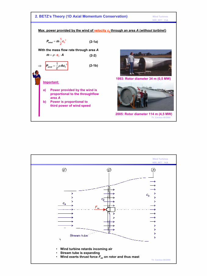
Max. power provided by the wind of velocity c0 through an area A (without turbine!)
With the mass flow rate through area A
⇒
= 20
12windP m c
= ⋅ ⋅m c Aρ 0
=windP Acρ 30
12
2. BETZ‘s Theory (1D Axial Momentum Conservation)
Important:
a) Power provided by the wind isproportional to the throughflowarea A
b) Power is proportional tothird power of wind speed
1993: Rotor diameter 34 m (0,5 MW)
2005: Rotor diameter 114 m (4,5 MW)
(2-1a)
(2-2)
(2-1b)
14Wind TurbinesN09_087/ A
Th. Carolus 08/2009
• Wind turbine retards incoming air• Stream tube is expanding• Wind exerts thrust force Fax on rotor and thus mast

8
15Wind TurbinesN09_087/ A
Th. Carolus 08/2009
Assumptions(1) Rotor replaced by a thin actuator disc at station D(2) Steady uniform flow upstream of the disc(3) Uniform and steady velocity at the disc(4) No wake rotation produced by the disc(5) Flow passing through the disc is contained both upstream and downstream
by the boundary stream tube(6) Flow is incompressible
16Wind TurbinesN09_087/ A
Th. Carolus 08/2009
Power extracted from the streamtube
(2-3)
Theoretical* shaft power of turbine
(2-4)
Thrust force Fax (acting on the mast)? Velocity in disc cD ?
Axial momentum conservation
(2-5)
* i.e. for inviscid flow
Combining Eq. (2-5) and (2-4)
as in Eq. (2-3)
⇒
⇒ Mass flow rate through rotor disc
Inserting everything in Eq. (2-4)⇒ Theoretical shaft power of turbine
= ⋅ − ⋅, 0 3( )S th DP m c c c
( )( )
−= = +
−
2 20 3
0 30 3
1122D
c cc c c
c c
( ) πρ ρ= ⋅ ⋅ = ⋅ + ⋅ 20 3
12 4Dm c A c c D
=,S thP P
( )
( ) ( )ρ
= ⋅ = ⋅ − ⋅ +
+ ⋅ − ⋅ +
, 0 3 0 3
0 3 0 3 0 3
1( )2
1 1 = ( )2 2
S th ax DP F c m c c c c
A c c c c c c
= ⋅,S th ax DP F c
= ⋅ −0 3( )axF m c c
= ⋅ −2 20 3
1( )2
P m c c
(2-6)

9
17Wind TurbinesN09_087/ A
Th. Carolus 08/2009
⇒
= = + − − ≡
(theoretical power coefficient)S,thP ,th
Wind
P c c c... CP c c c
2 3
2 2 2
1 1 1
1 12
3
0
cc
,P thc
(2-7)
Optimum:
Max. power for c3/c0 = 1/3; i.e. wind turbine must retard incoming flowto 33% of it original velocity
CP,th,opt = 16/27 = 0.593 or roughly 60%
CP,th,opt = 16/27 is the BETZ limit; maximum possible power coefficientof any wind turbine! (Albert BETZ, 1926)
18Wind TurbinesN09_087/ A
Th. Carolus 08/2009
≡
= ⋅ ⋅P
S P ,th
C
P C Acη ρ 30
12
• Turbine shaft power including various losses: (2-8)
• Effect of taking into account wake rotation: see next chapter
Hints

10
19Wind TurbinesN09_087/ A
Th. Carolus 08/2009
shaft power of he wind turbine
max. powerfrom thewind
=WindP Acρ 30
12
Pow
er [k
W]
Wind velocity at hub level [m/s]
Example: A 500 kW Wind Turbine
Enercon E40
20Wind TurbinesN09_087/ A
Th. Carolus 08/2009
3. Blade Element Analysis and Optimal Blade Design
=3 013
c c
( )= + =0 3 01 22 3Dc c c c
Introducing the „axial induction (retardation) factor“ a at rotor disc
( )= −3 01 2c a c
( )= − 01Dc a c
=13
a
So far: BETZ optimum (without wake rotation)
yields for the BETZ optimum a value of
(3-1)(3-2a)
3.1 Kinematics

11
21Wind TurbinesN09_087/ A
Th. Carolus 08/2009
and defining a‘ as the„tangential induction factor“
What are now optimum values?
( )= = −1 2 01m mc c a c
= ?a
Compare propeller:Wake downstream of rotor is rotating
Take complete flow kinematics including wake rotation into account for optimum wind turbine design
⇒ , , D m umc c c c2 21
= −2 02 'uc a c
=' ?a
⇒ , umc c c3 33
At disc:
Far wake:
Employing the previous axial induction factor
(3-2b)
(3-3)
Link between rotor geometry and performance - Optimum wind turbine design?
22Wind TurbinesN09_087/ A
Th. Carolus 08/2009
Thrust from axial momentum conservation on CV „coaxial strip“
( )= − = − 20 3 01 4ax mF c c m a( a )c r rδ δ ρ π δ (3-4)

12
23Wind TurbinesN09_087/ A
Th. Carolus 08/2009
Comparing Eqs. (3-4) and (3-5)
i.e. a and a‘ are not independent from each other
( ) ( )( ) ( )( )
( )
− = − + −
= + − − +
= −
= − +
2 2 2 22 1 1 2 2 1
22 2 22
22 2
2
2 2
2
222 1
D u D
u u
p p w w u u
u c u c c
uc c
u a' a'
ρ ρ
ρ
ρ
ρ
(1-11)
( )= −2 1axF p p Aδ δ
Thrust exerted on blade element (BE)
In axial cascade with incompressible flow ,
( )= +2 1 4axF u a' a' r rδ ρ π δ
( ) ( )− = +2 201 1a a c a' a' u
= =1 2m m Dc c c=1 2u u
⇒ (3-5)
⇒
⇒ (3-6a)
24Wind TurbinesN09_087/ A
Th. Carolus 08/2009
Define design tip-speed ratio
and local tip-speed ratio
=0
arcΩλ
( ) ( )− = + 21 1 ra a a' a' λ
( ) ( )−= − + + =2
11 1 12 2 r
r
a aa' f λ
λ
= =
0r
a
r ur c
λ λ
(3-7a)
(3-7b)
with a solution
Then Eq. (3-6a) becomes
(3-6b)
(3-8)

13
25Wind TurbinesN09_087/ A
Th. Carolus 08/2009= 30 2
2windP c r rρδ π δ
From EULER‘s equation (1-9a)
and with
and Eq. (3-8)
Now define BE power coefficient
= BEP ,BE
wind
PC
Pδδ
( )= = −22 2 01 4BE uP u c m u a' a c r rδ δ ρ π δ
= 30 2
2windP c r rρδ π δ
( ) ( )= − =21P ,BE r rC a' a fλ λ
Strategy for optimization:Given λr find a and a‘ for maximum CP,BE
0 0.1 0.2 0.3 0.4 0.50
0.1
0.2
0.3
0.4
0.5
0.6
a
CP,
BE
λr
⇒
(3-9)
(3-10)
26Wind TurbinesN09_087/ A
Th. Carolus 08/2009= 30 2
2windP c r rρδ π δ
Result
Conclusion:
(Only) for λr → ∞ the BETZ values are obained:a = 0.33a‘ = 0CP,BE = 0.59
For smaller values of λr the wake rotation reduces a, CP,BE,max and increases a‘
14
27Wind TurbinesN09_087/ A
Th. Carolus 08/2009
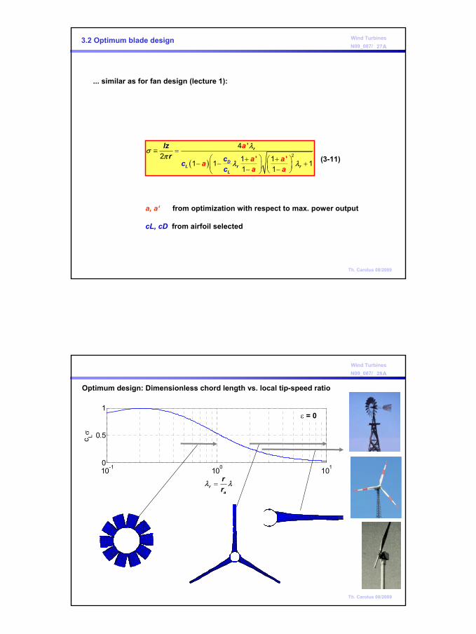
3.2 Optimum blade design
( )≡ =
+ + − − + − −
'
' 'r
Lr
D
r
L
a
a aa
lz
acc
rc
a
λσπ
λ λ2
42 1 11 1 1
1 1(3-11)
... similar as for fan design (lecture 1):
a, a‘ from optimization with respect to max. power output
cL, cD from airfoil selected
28Wind TurbinesN09_087/ A
Th. Carolus 08/2009
10-1 100 1010
0.5
1
c Lσ
Optimum design: Dimensionless chord length vs. local tip-speed ratio
=ra
rr
λ λ
ε = 0

15
29Wind TurbinesN09_087/ A
Th. Carolus 08/2009
Low and high tip-speed ratiowind turbines.
From the book by Albert BETZ : Windenergie und ihre Ausnutzung durch Windmühlen, 1926
30Wind TurbinesN09_087/ A
Th. Carolus 08/2009
HInt: Wind turbine jargon (mostly used but sometimes confused!)
α = local angle between chord and relative velocity = angle of attackβ∞ = local angle between plane of rotation and relative velocityγ = local angle between the chord and plane of rotation = pitch (angle)
twist = γ - γ(tip)
∞= −γ β α

16
31Wind TurbinesN09_087/ A
Th. Carolus 08/2009
References
• Gasch, R., Twele, J.: Wind Power Plants. Solarpraxis AG, Germany, 2002
• Burton, T., Sharpe, D., Jenkins, N, Bossanyi, E.: Wind Energy Handbook. John Wiley&Sons, Ltd, 2008
• Spera, D. A. (editor): Wind Turbine Technology. ASME Press 1998
• Brouchaert, J.-F. (editor): Wind Turbine Aerodynamics: A State-of-the-Art. Lecture Series 2007-5, von Karman Institute for Fluid Dynamics, Belgium
• Mathew, S.: Wind Energy, 2006
• Hanson, O.L.: Aerodynamics of Wind Turbines. earthscan 2009