lecture 21 flow and force analysis of valves 2/lecture 21.pdf · lecture 21 flow and force analysis...
TRANSCRIPT

1
Lecture 21
FLOW AND FORCE ANALYSIS OF VALVES
Learning Objectives
Upon completion of this chapter, the student should be able to:
Understand the mathematical equation for flow through anoverlapped four-way spool valve.
Understand the mathematical equation for flow through an underlappedfour-way spool valve.
Understand the mathematical equation for flow through athree-way critical center valve.
Understand the mathematical equation for flow through athree-way open center valve.
Describe the working and construction of a flapper nozzle valve and performits mathematical
analysis.
Analyze poppet, single-stage relief and pressure-compensated valves.
Carry out mathematical analysis of valves used inhydraulic systems.
1.1 Introduction
Most hydraulic servo mechanisms or other high-performance systems rely for their operation on the
metering of fluid through a valve. This chapter deals with a linearized method of analysis for “four-
way valves.” They are called so because they have four connections, one for the supply pressure and
another for the exhaust, and two control ports through both of which fluid may be metered, from the
supply to either the system or the exhaust.
Metering valves are never fully open and their use is for accurately metering the flow of fluid through
them. In this case of spool valves, longitudinal displacements of the spool are always small as
compared with the spool’s diameter.
1.2 Four-Way Spool Valves
A spool valve used for metering purposes controls flow rate by throttling.Each port in a valve that is
partially closed by a land on the spool becomes a control throttle.
The rate of flow of fluid through such a valve depends on the spool displacement from the null
position “x” and on the pressure upstream and downstream of the valve. One way of representing the
flow rate q through a valve is
q c mq K x K p (1.1)
whereqis the volume flow rate of the oil, Kq is the flow gain, Kc is the pressureflow coefficient and
pmis the pressure difference across the load.Equation(1.1) implies that the flow rate is directly
proportional to the valve opening and directly proportional to the pressure drop.
1.2.1 Critical Center Valve
In critical center valves, the lands of the spool are exactly of the same width as the annual ports of the
valve body in the central or null position where the lands exactly cover the ports (Fig. 1.1).

2
Figure 1.1 Four-way valve.
1.2.1.1 Flow Rate Prediction
Orifices are a basic means for the control of fluid power. Flow characteristics of orifices play a major
role in the design of many hydraulic control devices. An orifice is a sudden restriction of short length
in a flow passage and may have a fixed or variable area. Two types of flow regime exist depending on
whether inertial or viscous forces dominate. The flow through orifice must increase above that in the
upstream region to satisfy the law of continuity. At high Reynolds number, the pressure drop across
the orifice is caused by the acceleration of the fluid particles from the upstream velocity to the higher
jet velocity. At low Reynolds numbers, the pressure drop is caused by the internal shear forces
resulting from fluid viscosity.
The pressure difference required to accelerate the fluid particles from the lower upstream velocity to
higher upstream velocity is found by applying Bernoulli’s equation and continuity equation. Here we
will not derive the basic equations. Students are advised to go through any standard fluid mechanics
books for the derivation of flow through orifice.
From fluid mechanics, flow through the orifice is given by
1/2 1/2
1 d 1 s 1( ) (2 / )q C πd x p p ρ (1.2)
1/2 1/2
2 d 1 2 e( ) (2 / )q C πd x p p ρ (1.3)
Let us make following assumptions:
1. 1 2q q
2. s 1 2 e( ) ( )p p p p
3. the supply pressure (sp ) is constant
4. ep is negligible
x
c
x
Load
x
3
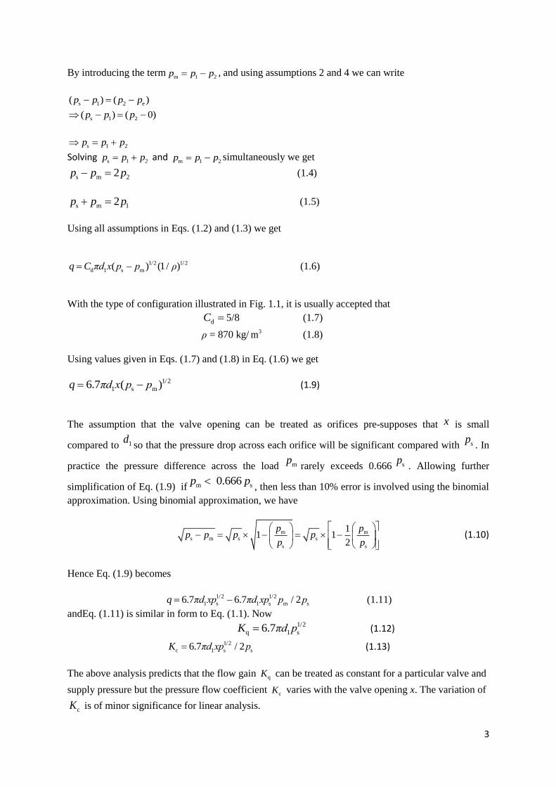
By introducing the term1m 2p p p , and using assumptions 2 and 4 we can write
s 1 2 e( ) ( )p p p p
s 1 2( ) ( 0)p p p
s 1 2p p p
Solving s 1 2p p p and
1m 2p p p simultaneously we get
s m 22p p p (1.4)
s m 12p p p (1.5)
Using all assumptions in Eqs. (1.2) and (1.3) we get
1/2 1/2
d 1 s m( ) (1/ )q C πd x p p ρ (1.6)
With the type of configuration illustrated in Fig. 1.1, it is usually accepted that
dC 5/8 (1.7)
ρ = 870 kg/ 3m (1.8)
Using values given in Eqs. (1.7) and (1.8) in Eq. (1.6) we get
1/2
1 s m6.7 ( )q πd x p p (1.9)
The assumption that the valve opening can be treated as orifices pre-supposes that x is small
compared to 1dso that the pressure drop across each orifice will be significant compared with sp
. In
practice the pressure difference across the load mprarely exceeds 0.666 sp
. Allowing further
simplification of Eq. (1.9) if m s 0.666 p p, then less than 10% error is involved using the binomial
approximation. Using binomial approximation, we have
m ms m s s
s s
11 1
2
p pp p p p
p p
(1.10)
Hence Eq. (1.9) becomes
1/2 1/2
1 s 1 s m s6.7 6.7 / 2q πd xp πd xp p p (1.11)
andEq. (1.11) is similar in form to Eq. (1.1). Now 1/2
q 1 s6.7K πd p (1.12)
1/2
c 1 s s6.7 / 2K πd xp p (1.13)
The above analysis predicts that the flow gain qK can be treated as constant for a particular valve and
supply pressure but the pressure flow coefficient cK varies with the valve opening x. The variation of
cK is of minor significance for linear analysis.

4
In reality, spool lands never exactly match the annular ports in the valve body. Actual test results with
a constant pressure drop across the valve ports show variations, particularly near the central or null
position of the spool as those illustrated in Fig. 1.2.
The flow gain qK is the slope of the approximate line in the figure, which can double its valve near
null with negative lap. The magnitude of qK is the most important parameter of a valve and often also
of any system incorporating the valve.
Figure 1.2Flow rates versus valve displacement for constant pressure drop.
1.2.2 Open Center Valve (Underlapped Four-Way Valve)
A valve in which the land of the spool never completely covers the ports of the valve body is said to
be underlapped(or to have negative lap)(Fig. 1.3).
Figure 1.3 Open center–four-way valve.
(u+x)
(u+x)
d c b a
(ux)
Load
(ux)
Load motion
x
Zero lap
Overlap
Underlap

5
Referring to Fig. 1.3,a displacement of x(say to the left) unbalances the symmetry of the ports. Two of
the annular orifices increase in width from u to u + x and two decrease from u to u−x.The flow
ratesare estimated as follows:
1/2 1/2
1/2 1/2
1 d 1 s 1 d 1 1 e
2 2( )( ) ( )( )q C πd u x p p C πd u x p p
ρ ρ
(1.14)
1/2 1/2
1/2 1/2
2 d 1 2 e d 1 s 2
2 2( )( ) ( )( )q C πd u x p p C πd u x p p
ρ ρ
(1.15)
Let us make following assumptions:
1. 1 2q q
2. 2s 1p pp
3. The supply pressure (sp ) is constant
4. ep is negligible
Writing m 1 2p p p , we can use these assumptions in Eqs. (1.14) and (1.15) and get
1/2
1/2 1/2
d 1 s m s m
1{( )( ) ( )( ) }q C πd u x p p u x p p
ρ
(1.16)
that may be approximated as
1/2 1/2 1/2
1/2 1/m 2
1 d 1m
s
s s
s
1 1 1( )( ) 1 ( )( ) 1
p pq C πd u x p u x p
2 p 2 p ρ
(1.17)
1/
s
2 1/2 1/21/2 s m
d 1 s d 1
1 12
p pq C πd p x C
pπd u
ρ ρ
(1.18)
Equation (1.18) is similar in form to Eq. (1.1):
1/2
q 1 s13.4K πd p (1.19)
1/2
c 1 s s6.7 /K πd xp p (1.20)
The values refer to operation within the underlap region. Outside this region, these valves act as
critical center valves with only two active ports. Note particularly that the flow gain qKis double that
for a comparable critical center valve (Fig. 152) in the underlap region. Note also significant leakage
flow when the valve is centered (leakage flow at null when the load flow q is zero)becomes 1/2
1 s13.4πd p.
1.3 Three-Way Spool Valves
Three-way valves have only one critical length dimension which helps to ease manufacture. However
they cannot be used for hydraulic motors requiring flow reversal and are usually used in differential
ram and is discussed below.

6
1.3.1 Critical Center Valve
The central spool position just closes both the supply and the exhaust port of the valve. A
displacement of the spool to the left causes fluid to be metered into the ram chamber from the supply,
whereas one to the right causes metering of fluid from the chamber to the exhaust (Fig. 1.4).
Figure 1.4 Three-way valve.
Oil flow rate is
qc = Cdπ d1x
1/2
1/2
s c
2( )p p
ρ
forxpositive (1.21)
qc = Cdπ d1x
1/2
1/2
c e
2( )p p
ρ
for x negative (1.22)
Substituting pm = pc −ps/2 we get
qc = Cdπ d1x
1/21/2
s
m
2–
2
pp
ρ
for x positive (1.23)
qc = Cdπ d1x
1/21/2
s
m
2
2
pp
ρ
for x negative (1.24)
thatmay be approximated.Noting that
1/2
s
m2
pp
=
1/2
s m
s
21
2
p p
p
≈
1/2
s m
s
211
2 2
p p
p
(1.25)
we get
qc = Cdπ d1x
1/2
1/2
s
1( )p
ρ
Cdπ d1x
1/2
s m
s
1( ) p p
p (1.25)
where the positive sign is associated with negative values of x and negative sign with positive
ones.Using Cd1/2(1/ )ρ 6.7 for SI units with pressure in bars we get
Kq= 6.7 π d11/2
s( )p (1.26)
Kc= 6.7 π d1m
s
px
p
(1.27)
c
x
x
Positive valve
displacement
Positive load
displacement

7
1.3.2 Open Center Valve (Underlapped Three-Way Valve)
Figure 1.5 Open center–three-way valve.
Referring to Fig. 1.5, The orifice equation for q1 can be written as
q1 = Cdπ d1(u + x)
1/2
1/2
s c
2( )p p
ρ
(1.28)
Using binomial approximation we can write
q2 ≈Cdπ d1(u + x) 1/2
1/2 ms
s
11
pp
ρ p
(1.29)
Similarly orifice equation for q2 can be written as
q2 = Cdπ d1(u − x)
1/2
1/2
c
2( )p
ρ
(1.30)
Using binomial approximation we can write
q2 ≈ Cdπ d1(u − x) 1/2
1/2 ms
s
11
pp
ρ p
(1.31)
The flow rateqc is the difference of q1 and q2, that is
qc = q1 – q2
≈ Cdπ d1 1/2
1/2
s
1p
ρ
2x − Cdπ d1 1/2
1/2
s m
s
1 2
up p
ρ p
(1.32)
Comparing with Eq. (1.1) we can write
Kq= 13.4 π d11/2
s( )p (1.33)
Kq= 13.4 π d1u
1/2
s
s
p
p (1.34)
x
(ux) (u+x)

8
1.4 Flapper Nozzle Valve
Commonly used asthe first stage of two-stage servo valves, nozzles and the fixed upstream orifices
used with them are made with diametersnd and
0d in the range 0.2–0.8 mm and the distance 0x
between each nozzle and the flapper in a double valve is often less than 0.2 mm.Each nozzle and
orifice is as nearly a sharp-edged orifice as possible and treated as such for analytical purposes. The
curtain area formed by the flapper at a nozzle exit modulates the control pressure caused by the fixed
upstream orifice.
Figure 1.6 Flapper nozzle valve.
Consider a flopper nozzle valve indicated in Fig. 1.6. We assume that the valve has a balanced
condition such that x = 0 and mp = 0, q = 0. This occurs with the pressure downstream of each of the
fixed orifices iequal tops/2 and when the flow through each orifice equals that through each nozzle,
that is
1q (steady state) =3q (steady state) =
0
1/2 1/2
0 s s( / 2) (2 / )dC A p p ρ (1.35)
2q (steady state) =4q (steady state) =
n
1/2 1/2
n 0 s( / 2) (2 / )dC πd x p ρ (1.36)
and 1 2 3 4q q q q
This also implies that the orifice size and the curtain area in the null position are approximately equal
0 0dC A =n n 0dC πd x
Let us assume feasible ratio of
n o
3
2d d
nd =
08x (1.37)
Consideringthat the valve is not in balance, that is,x has the same value as mp has, we have
q =1 2q q
1/2 1/2
s s mn
0mn s
02 2 2 2
p pp pK p K
x x
x
(1.38)
where
0
1/ 2
n 0 (2/ )dK C A ρ =n
1/ 2
n 0(2 / )dC πd x ρ
Also
q =3 4 q q
1/2 1/2
s sm mn s n
0
02 2 2 2
p pp pK p K
x x
x
(1.39)
Load
Orifice area
diameter
Flapper

9
Using binomial approximations, we have
1/2 1/2 1/2
s s s sm m mn n n
s 0s
1 12 2 2 2 2 2 2
p p p pp p pxq
xK K K
p p
(1.40)
1/2 1/2 1/2
s s s sm m mn
s 0
n n
s2 2 2 2 2 2 21 1
p p p pp p pKq
p
x
xK K
p
(1.41)
Adding and dividing by 2, we get
q= 1/2
n s m s( / 2) /K p p p +1/2
n 0 s( / )( / 2)K x x p (1.42)
thatis in the form of q c mq K x K p . Now
1/2
q n 0 s/ ( / 2)K K x p =n
1/2 1/2
n s(2 / ) ( / 2)dC πd ρ p
1/2
c n s s/ ( / 2)K K p p =n
1/2 1/2
n s s( / )(2 / ) ( / 2)dC πd p ρ p
=0
1/2 1/2
0 s s ( / )(2 / ) ( / 2)dC A p ρ p
1.5 Special-Purpose Valves
The dynamic characteristics of hydraulic devices such as relief valves or flow-control valves are not
well understood. For design purposes, it is useful to know the likely influence of spool mass, spring
rate, orifice size or other parameter on the response of any particular valve to changes in pressure or
flow rate or to other disturbances. A pressure-control valve and a flow-control valve are considered
below.
1.5.1 Poppet Valves
Pressure control valve and flow control valves employs a poppet valve (Fig. 1.7) and their
characteristics will be influenced by the flow pattern existing at or near the valve seat.
Figure 1.7 Poppet valve.
For a poppet displacement x, the area of flow is Cdx π d sinψ , where Cd is the flow coefficient. For a
pressure drop of p across the orifice formed between the seat and poppet, the fluid velocity v is
taken as equal to 1/2
2 p
ρ
(1.43)
and the volume flow rate as
q= Cdx π d
1/2
2 sinψ
p
ρ
(1.44)
The momentum of the jet has an axial component equal to ṁv cosψ (where ṁ is the mass flow rate)
that may be written as
Axial component of momentum of jet ( = Mass flow rate ×Velocity

10
= Density ×Volume flow rate ×Velocity component
1/2 1/2
axial
2 2 ( ) sin cosd
p pm C x d ψ ψ
ρ ρ
(1.45)
Please checkEq. (1.45)
where
λ = Cdπ d sin2ψ (1.46)
The axial component of jet momentum is λ p x.
1.5.2 Single-Stage Relief Valve
Spring loaded valve is illustrated in Fig. 1.8. Let the pressure applied to valve to open is pIt is the
effects of small changes in this pressure from op to op p that are to be considered. The outlet
(exhaust) pressure is assumed to be zero throughout.
Figure 1.8 Relief valve.
With the poppet closed (i.e.,x = 0), there is some spring-related preload force holding it down that is
designated as F. Under a steady-state condition with a greater pressure applied than that needed to
overcome the preload, the valve partly opened and the poppet stationary, there is a steady-state
balance of forces relating this pressure to the poppet displacement. For the applied pressure p0 and the
poppet displacement x0, the relation is
op2
4
πd= F+ ksx0+ λ op x0 (1.47)
If the approach velocity is negligible then λ , given in Eq. (1.46), and the fluid frictional drag force
across the poppet face is neglected.
For some other steady-state position of the poppet (displacement ox x ), another pressure op p
would occur according to
( op p ) 2
4
πdF+ks( ox x ) + λ ( op p )(
ox x ) (1.48)
Note that Eqs. (1.47) and (1.48) refer to steady state with poppet stationary. Under dynamic
conditions with the poppet moving, the balance of forces has to take into account the effective mass of
the poppet m and any damping (assumed viscous of rate f) as well as spring, pressure and momentum
forces. For a pressure op p and a poppet displacementox x , the balance forces become
( op p ) 2
4
πdF+ ksx0 + λ op x0 + λ x0 p + (ks + λ p0) x + f Dx + mD
2x (1.49)
(m)
( )

11
Assume that the terms involving px are negligibly small. Subtracting Eq. (1.47) from Eq. (1.49), we
get
2
4
πdp − pλ x0= (ks+ λ op ) x +f Dx + mD
2x
Indicating a second-order relation between changes in pressure p and changes in poppet
displacement x given by
2
2
n n
1 21
x K
pD D
(1.50)
where 2
0
o
( / 4 )
( )
πd λ xK
ks λ p
= (ks+ λ op ) /m
This relation suggests that any oscillation of the poppet is associated with much stiffer spring than the
physical spring constant would suggest. As a numerical example, consider a valve of diameter d =
6mm for use at a nominal pressure of op = 70 bar. The projected area equals 28 2mm , so that the
value of F is approximately 20 N andif this is obtained by initially compressing the spring 10mm, the
spring rate would have a valve of ks = 20 N/mm. Assume that the poppet has a 90 cone angle and
flow coefficient dc = 0.7, then λ for the valve is about 13.2 mm and λ
op = 92.4 N/mm. The
effective spring rate is not 20 but 112.4 N/mm. If the effective mass were 0.001 kg, then the natural
frequency n of poppet oscillations would be 533 Hz.
1.6 Pressure-Compensated Flow-Control Valve
Figure 1.9 illustrates a pressure-compensated flow-control valve which is designed to pass a constant
flow rate of fluid despite fluctuations of the inlet and outlet pressures. The device has two orifices in
series:one is preset manually to select the desired flow rate, while the other varies with the pressure
difference across the valve. The aim is to keep the flow rate constant by maintaining a constant
pressure difference across the present orifice.
For analysis, changes in the outlet pressure Lp represent the disturbances externally imposed on the
device with the inlet (supply) pressure sp assumed constant. This simulates a meter-in control with
the poppet valve partly open and this analysis concerns small changes in this valve opening. The fully
open or fully closed conditions are not dealt with. The datum for spring force acting on the spool is
taken from some arbitrary position of the spool represented by the poppet (i.e., control orifice)
opening of o .x

12
Figure 1.9 Pressure-compensated flow-control valve.
1.6.1 Forces
The steady-state balance of forces for some equilibrium operating position with the poppet stationary
and open distance0x , for a supply pressure sp , outlet pressure Lop and consequent chamber pressure
Cop is given by
(Cop − Lop ) pA = F− λ (
sp −Cop )
ox (1.51)
Under dynamic conditions with the spool in motion for the outlet pressure Lop + Lp , with the
instantaneous spool position distance x to the left of its initial position, noting that Cop +
cp is the
instantaneous chamber pressure, the balance of forces is given by
{(Cop +
cp ) −( Lop + Lp } pA = F−
sk x– λ {sp –(
Cop +cp )}(x+
ox )−f Dx – mD2x (1.52)
Assuming thatcp Lp and xare small and the terms cp x may be neglected, subtracting Eq. (1.52) from
Eq. (1.51) gives
−cp = s s Co
o
( )k λ p p
Ap λx
x +
o
f
Ap λxDx +
o
m
Ap λxD
2x−
o
Ap
Ap λxLp (1.53)
1.6.2 Flow Rates
Under steady-state condition, the flow rate through control orifice must be equal to that through the
preset orifice. Hence, for the steady conditions previously used with the constant sp , the outlet Lop ,
the chamber pressure Cop and control orifice opening ox using the subscript e for the preset orifice,
q0 = Cdx0π d
1/2
s Co2( )p p
ρ
= Cdeae
1/2
Co Lo2( )p p
ρ
(1.54)
Under dynamic conditions, the flow rate through the control orifice will no longer be equal – the flow
through the control orifice iso iq q and that through preset orifice
o eq q . The difference between the
two flow rates (into and out from the valve chamber) causes compression of the oil in the valve
chamber or
o i c V
q q D p
(1.55)
Manually
preset orifice
Spring
Oil inlet
Annular
control orifice
Oil outlet
Moving spool

13
whereV is the volume of oil and is the effective bulk modules. In Eq. (1.55),V is assumed to be
constant.The flow rate through the control orifice may be written as
1/2
2
o i o s Co c p
2 ( ) { – ( )} q q Cd x x π d p p p A Dx
ρ
(1.56)
Subtracting Eq.(1.54)from Eq. (1.56) neglecting the terms involving cp x we get
iq = − o c
s Co2 pp
q p
+ o
o
q
xx +ApDx (1.57)
and similarly for the change in flow rate through the preset orifice,
eq = = o c
s Lo2
q p
p p− o L
Co Lo
2
q p
p p (1.58)
Now subtracting Eq. (1.58) from Eq.(1.57) gives
i eq q = pA Dx+ o
o
q
xx+ o oL
c
Co Lo s Co Co Lo
1 1
2 2
q qpp
p p p p p p
(1.59)
Also equating Eqs. (1.55) and (1.59) after substituting Eq. (1.53) for cp and after differentiating, for
Dcp to obtain
cp andDcp terms of Lp and x leads to (closed loop) relation between displacements of
the spool and changes of the outlet pressure
3
oa D x + 2
1a D x + 2a D x + 3a x = K
Lp + TDLp (1.60)
3 2
L o 1 2 3
x K TD
p a D a D a D a
(1.61)
where
o
3 s p o
o
( )q
a k Q A xx
2 s p p o ( )
Va fQ k A A x
1
Va mQ f
0
Va m
p
VT A
K =
o op o
s Co Co Lo2 2
q qA λx
p pp p
Q =
o o
s Co Co Lo2 2
q q
p p p p
s s s Co( )k k λ P P
This linear equation is obviously difficult to apply particularly as the coefficients depend on the initial
conditions that might be classed as the “normal” operating conditions. In practice,the valves of this
type can be unsatisfactory at initial stage. The relation does indicate that a value is stable if 1 2a a is
greater than 3 oa a and confirms that increasing the viscous damping helps to stabilize the valve,
increasing both 1a and 2a .

14
Example 1.1
A four-way valve with full periphery annular ports has a 6 mm diameter spool and it may be assumed
that the spool lands fully cover the valve ports in zero or mid-position. Estimate the flow rate through
one port when the pressure drop across it is 70 bar for every mm of spool displacement.
Solution
Spool diameter (d) = 6mm
Pressure drop (Δp) = 70 bar
Spool displacement (x) = 1mm
By the orifice flow equation, theflow rate is
d 2Δ /q C πdx p ρ
Letting Cd = 5/8 and ρ = 870 kg/m3 and Δpin bar, we have
6.7 2Δq πdx p
Therefore,
q= 6.7 π(6 × 10³
) × (1 × 10³
) × 2 70
q= 1.494 × 10³
m3/s
Example1.2
What would be the flow coefficient Kq of the above valve if it is used as part of a servo system
having oil supply pressure: (a) 140 bar, (b) 210 bar?
Solution:
(a) Supply pressure (ps) = 140 bar. We know q s6.7K πd p . Therefore,
Kq = 6.7×π(6 × 10³
) × 140 = 1.494 m3/s/mm
(b)Supply pressure (ps) = 210 bar. We know q s6.7K πd p . Therefore,
Kq = 6.7 × π (6 × 10³
) × 210 = 1.83 m3/s/mm
Example1.3
A three-way spool valve with half the annular periphery of the valve port blocked off and spool
diameter 9 mm is used in a system supplied with oil at 120 bar pressure. The half-area piston has
areas 0.004 m2 and 0.002 m
2 and a maximum required velocity 0.3 m/s. Estimate the maximum spool
displacement required. (Assume one-third pressure drop through valve.)
Solution: Supply pressure (ps) = 120 bar. Spool diameter (d) = 9mm. Piston area (Ap) = 0.004m2
.
Maximum velocity (v) = 0.3m/s. Maximum valve flow rate is
Q = Ap × v = 0.004×0.3 = 1.2 × 10⁻³
m3/s
Pressure difference across load (pm) = 40 bar (one-third of supply pressure).
For a three-way valve with half-area piston, the pressure drop is
Δp = (ps/2) −pm = 20 bar
Also from the orifice equation we can write

15
q= 6.7 × π (9 × 10⁻³
) × x × 2 20
q= 1.198 × x
Equating two values of Q and q, we have
1.2 × 103
= 1.198 × x
x = 1.0016mm.
As half the annular periphery of valve is blocked, for the same flow rate, the displacement required is
twice the calculated value.Therefore, the valve displacement is
y = 2 × x = 2.003mm
Example 1.4
In a 240-bar servo system employing a four-way valve, a valve underlap is used to assist in damping
system oscillations. The valve has a 4-mm-diameter spool, full periphery ports and nominal underlap
of 0.0127 mm. Estimate the pressureflow coefficient Kc for the valve.
Solution: Supply pressure (ps) = 240 bar. Spool diameter (d) = 4mm. Underlap(u) = 0.0127mm. We
know 3 3
9 3
c
s
6.7 6.7 (4 10 )(0.0
240
127 10 )6.9 10 m /s/bar
pduK
p

16
Objective-Type Questions
Fill in the Blanks
1. In critical center valves, the lands of the spool are of the ______ as the annual ports of the valve
body in the central or null position where the lands exactly cover the ports.
2. A valve in which the land of the spool never completely covers the ports of the valve body is said
to be ______.
3. ______ is commonly used as the first stage of two-stage servo valves.
4. A pressure-compensated flow control valve is designed to pass a ______ of fluid despite
fluctuations of the inlet and outlet pressures.
5. Flow gain can be treated as ______ for a particular valve and supply pressure.
State True or False
1. The central spool position just closes both the supply and the exhaust port of the valve.
2. Most hydraulic servo mechanisms or other high-performance systems rely for their operation on the
metering of fluid through a valve.
3. Metering valves are always fully open and their use is for accurately metering the flow of fluid
through them.
4. A spool valve used for metering purposes controls flow rate by throttling.
5. A pressure flow coefficient will vary with valve opening and the variation of pressure flow
coefficient are of major significance for linear analysis.
Review Questions
1. Discuss in detail the flow–displacement relationship of a critical center spool valve, giving its
possible applications in hydraulic control valves.
2. Discuss in detail the flow forces acting on apressure-compensated flow control valve and derive an
expression for these forces.
3. Derive an expression for the flow–displacement relations of anunderlapped four-way valve.
4. Derive an expression for the flow for a flapper nozzle valve.
5.What is the major limitation of a flapper nozzle amplifier and how it can be overcome?
6.Why is a feedback system used in a multistage servo valve?
7. What is a critical center valve?
8. What does an underlapped four-way valve mean?
9. Give two applications of a flapper nozzle valve.
10. How is a higher flow rate achieved in an electrohydraulic servo valve?
11. Why is a feedback system used in a multistage servo valve?
12. Illustrate the two different types of feedbacks used in a multistage electrohydraulic valve?
13. What is the major limitation of a flapper nozzle amplifier and how it can be overcome?
Answers
Fill in the Blanks
1.Same width
2.Underlapped
3.Flapper nozzle valve
4.Constant flow rate
5.Constant
State True or False
1.True
2.True
3.False
4.True
5.False

17