lecture 13: rotational dynamics
TRANSCRIPT

79 UTA Physics Department - Technical Physics I Lecture Notes
All Rights Reserved
Lecture 13: Rotational Dynamics
Physics for Engineers & Scientists (Giancoli): Chapter 10
University Physics V1 (Openstax): Chapter 10
Rotational Vectors
While we are able to treat rotational variables one-dimensionally in most cases, they are still
vectors with magnitude and direction.
The direction of rotational vectors is defined to be either parallel or anti-parallel to the axis of
rotation. Anti-parallel means parallel but pointing the opposite direction.
If the object is rotating counter-clockwise in an xy-plane when viewed from above, then ω points
upward in the z-direction.
If the object is rotating clockwise in an xy-plane when viewed from above, then ω points
downward in the negative z-direction.
Rotational Dynamics
As rotational kinematics showed many similarities with one-dimensional translational
kinematics, we can expect more similarities to appear in dynamics, but there are some
differences too.
Concept Translational (1D) Rotational Relationship
Position x (or S) θ S = rθ
Velocity v ω v = rω
Acceleration a α aT = rα
Cause of Acceleration F τ (Torque) (| | )
Inertia m I (Moment of Inertia) dI = r2dm
Newton‟s 2nd
Law
Work W = Fd W = τθ
Kinetic Energy KETranslational = ½mv2 KERotational = ½Iω
2
Momentum
Force/Momentum
2021-7-15

80 UTA Physics Department - Technical Physics I Lecture Notes
All Rights Reserved
Moment of Inertia (I)
The moment of inertia is the rotational equivalent of mass (a resistance to being spun).
An object in uniform circular motion can be looked at as either rotational
motion or as in linear translational motion (at least temporarily).
The kinetic energy of this motion should be the same either
way it is calculated. This allows us to determine a
relationship between moment of Inertia (I) and mass (m).
( )
Note: This is only valid when all the mass is located at the
same distance (r) from the axis of rotation.
When the mass is not all at the same value of r, you must calculate the mass at each value of r
and sum them all up. As there is often a continuous distribution of r values, summing may mean
integration.
∫
Example: Determine the moment of inertia of a solid cylindrical disk of uniform density, mass M, and
radius R.
Step 1: Split mass into small pieces, each with the same value of r (as r appears in our equation). In
this case, it will be infinitesimally thin cylindrical shells.
The left image shows the cylinder and its dimensions (R and h).
The center image shows one of the small pieces, a hollow cylinder in the center (orange).
The right image is a view from above. The thickness of the shell is dr.
Step 2: Find „dm‟, the mass of a representative shell.
( ) ( )
A is the surface area of the cylindrical shell. The length is the circumference and the width is h.
( ) (
)
2021-7-15

81 UTA Physics Department - Technical Physics I Lecture Notes
All Rights Reserved
Be careful with your variables. Don’t confuse R and r. R is the radius of
the cylindrical disk. r is the radius of the thin cylindrical shell.
Step 3: Plug in and integrate.
∫
∫ (
)
∫
[
]
[
]
Example: Find the moment of inertia for a flat (right) triangular plate if it is rotating around the y-axis.
You may assume uniform thickness and density.
Step 1: Split mass into small pieces, each with the same value of r (as r appears in our equation).
In this case the distance from the axis of rotation (the y-axis), is just x. (r = x)
Step 2: Find „dm‟, the mass of the strip.
In this instance, we must find y as a function of x
(since y varies with x).
( )
We also need the value of ρ.
Step 3: Plug in and integrate.
∫
∫
∫ ( )
∫
( )
∫ ( )
[
]
[
]
[
(
)
( )
]
[
]
[
]
Most of the time you will simply pull a formula from a table of standard shapes.
2021-7-15
82 UTA Physics Department - Technical Physics I Lecture Notes
All Rights Reserved
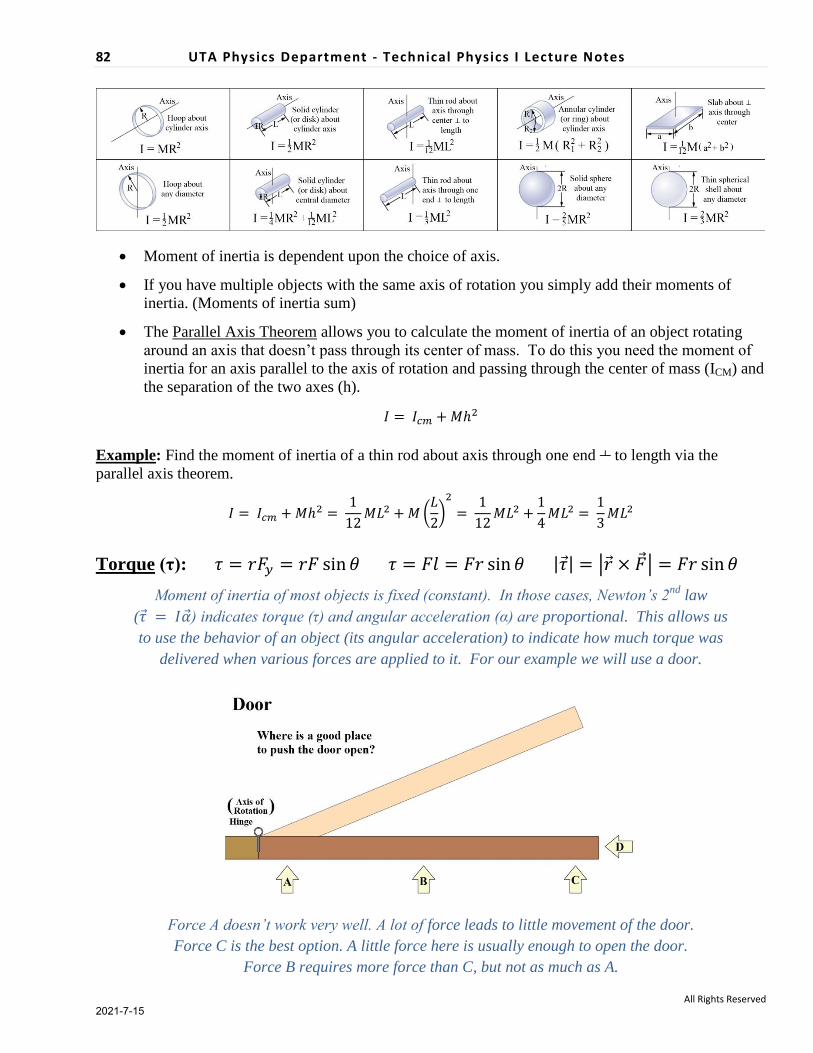
Moment of inertia is dependent upon the choice of axis.
If you have multiple objects with the same axis of rotation you simply add their moments of
inertia. (Moments of inertia sum)
The Parallel Axis Theorem allows you to calculate the moment of inertia of an object rotating
around an axis that doesn‟t pass through its center of mass. To do this you need the moment of
inertia for an axis parallel to the axis of rotation and passing through the center of mass (ICM) and
the separation of the two axes (h).
Example: Find the moment of inertia of a thin rod about axis through one end to length via the
parallel axis theorem.
(
)
Torque (τ): | | | |
Moment of inertia of most objects is fixed (constant). In those cases, Newton’s 2nd
law
( ) indicates torque (τ) and angular acceleration (α) are proportional. This allows us
to use the behavior of an object (its angular acceleration) to indicate how much torque was
delivered when various forces are applied to it. For our example we will use a door.
Force A doesn’t work very well. A lot of force leads to little movement of the door.
Force C is the best option. A little force here is usually enough to open the door.
Force B requires more force than C, but not as much as A.
2021-7-15

83 UTA Physics Department - Technical Physics I Lecture Notes
All Rights Reserved
Force D doesn’t open the door at all.
Any force that acts through the axis of rotation generates no torque.
To generate torque a force must have a a component ┴ to the line connecting the axis of
rotation to the point where the force acts.
The further from the axis of rotation the force is applied the greater the torque.
If we apply a force to an object, we define the vector to start at the axis of rotation and at the
position where the force is applied. θ is defined to be the angle between and .
Breaking into component (parallel and perpendicular to ) we find:
Fx (the component parallel to ) generates NO torque.
Fy (the component perpendicular to ) generates positive torque as it rotates the door
counter clockwise (CCW).
The magnitude of the torque ( | |) is given by:
Forces that create clockwise (CW) rotations are generating negative torque.
Breaking into component (parallel and perpendicular to ) we find:
The component parallel to has no bearing on the torque at all.
The component perpendicular to is called the Lever Arm (l), and it is directly related to
the torque. Any increase in the lever arm gives a proportional increase in torque ( ).
The magnitude of the torque ( | |) is given by:
We gain “Leverage” by increasing the lever arm.
Both viewpoints give the same result, which is often represented as a vector cross product.
2021-7-15

84 UTA Physics Department - Technical Physics I Lecture Notes
All Rights Reserved
| | | |
There are more advanced methods of calculating vector cross products, but these are
rarely used for torque (as we already know the direction along the axis of rotation).
Example: Three forces act on a compound wheel as shown. The forces come from ropes wrapped
around the edges of the wheel. The moment of inertia of the wheel is 30.0 kg·m2 with an inner radius of
r1= 25.0 cm and an outer radius of r2 = 50.0 cm. Determine the angular acceleration of the wheel in
response to the three forces: F1 = 80.0 N, F2 = 30.0 N, and F3 = 20.0 N.
Use Newton’s 2nd
Law: ∑
To find the torque for each force vector:
(1) Determine sign on torque: CCW is ‘+’,
CW is ‘-‘
(2) Find the vector , note it’s magnitude
(3) Determine the angle between and
(that’s θ)
(4)
∑
∑ ( )( ) ( )( ) (( ))( )
∑
2021-7-15