lecture 12: 3d hidden surface removal
TRANSCRIPT


Lecture 12: 3D Hidden Surface Removal
CITS 3003 Graphics & AnimationE. Angel and D. Shreiner: Interactive Computer Graphics 6E © Addison-Wesley 2012

Breakdown of Lectures
1. Introduction & Image Formation2. Programming with OpenGL3. OpenGL: Pipeline Architecture4. OpenGL: An Example Program5. Vertex and Fragment Shaders 16. Vertex and Fragment Shaders 27. Representation and Coordinate
Systems8. Coordinate Frame Transformations9. Transformations and Homogeneous
Coordinates10. Input, Interaction and Callbacks11. More on Callbacks12. Mid-semester Test
Study break13. 3D Hidden Surface Removal14. Mid term-test and project discussion
15. Computer Viewing16. Shading17. Shading Models18. Shading in OpenGL19. Texture Mapping20. Texture Mapping in OpenGL 21. Hierarchical Modelling22. 3D Modelling: Subdivision Surfaces23. Animation Fundamentals and
Quaternions24. Skinning
4

Announcement
No in-class lecture
tomorrow

Content
• Look into a more sophisticated three-dimensional example
– Sierpinski gasket: a fractal
• Introduce hidden-surface removal
– The z-buffer algorithm
– The Painter’s algorithm
• Animation and double buffering
6

Three-dimensional Applications
• In OpenGL, two-dimensional applications are a special case of three-dimensional graphics
• Going from 2D to 3D:o Not much changes
o Use vec3, glUniform3f
o Need to worry about the order in which primitives are rendered, or
o Need to do hidden-surface removal
7
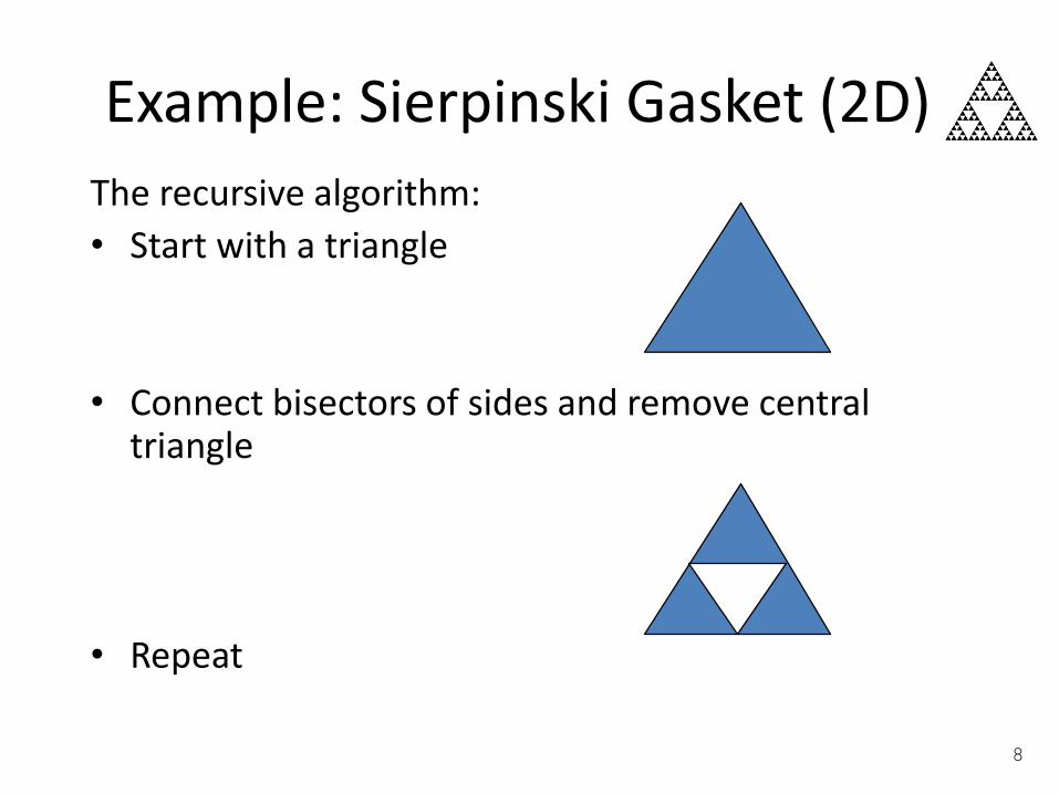
Example: Sierpinski Gasket (2D)
The recursive algorithm:
• Start with a triangle
• Connect bisectors of sides and remove central triangle
• Repeat
8
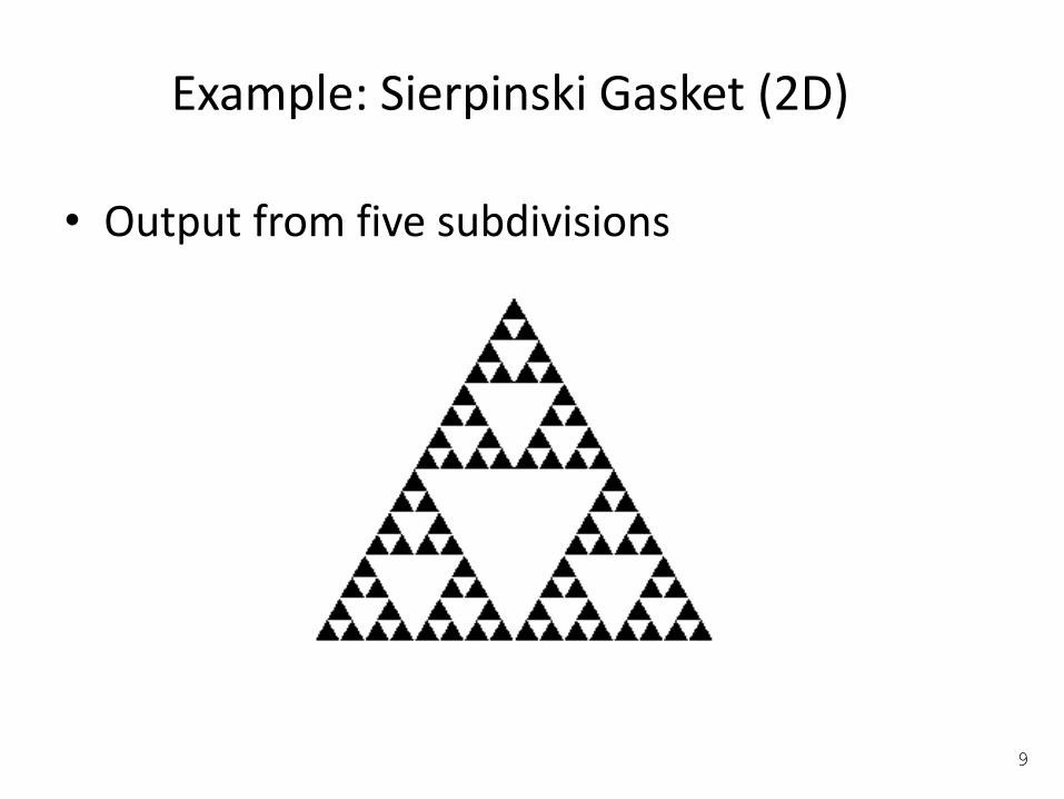
Example: Sierpinski Gasket (2D)
• Output from five subdivisions
9

Fractals in Graphics
“My power flurries through the air into the ground.
My soul is spiraling in frozen fractals all around.
And one thought crystallizes like an icy blast-
I’m never going back; the past is in the past!”Queen Elsa, Frozen
Mandlebulb
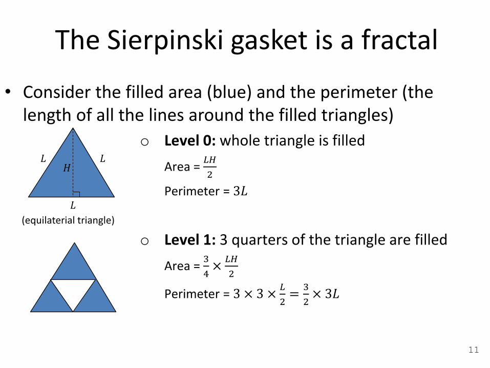
The Sierpinski gasket is a fractal
• Consider the filled area (blue) and the perimeter (the length of all the lines around the filled triangles)
o Level 0: whole triangle is filled
Area = 𝐿𝐻
2
Perimeter = 3𝐿
o Level 1: 3 quarters of the triangle are filled
Area = 3
4×𝐿𝐻
2
Perimeter = 3 × 3 ×𝐿
2=
3
2× 3𝐿
(equilaterial triangle)
𝐻𝐿 𝐿
𝐿
11

The Sierpinski gasket is a fractal
• Consider the filled area (blue) and the perimeter (the length of all the lines around the filled triangles)
o Level 2: 3 quarters of the filled triangles at level 1 are filled
Area = 3
4×3
4×𝐿𝐻
2=
3
4
2 𝐿𝐻
2
Perimeter = 9 × 3 ×𝐿
4=
3
2
23𝐿
o Level 𝒏:
Area = 3
4
𝑛 𝐿𝐻
2
Perimeter = 3
2
𝑛3𝐿
∴ As 𝑛 → ∞, Area → 0Perimeter → ∞
12

The Sierpinski gasket is a fractal
• As we continue subdividing
– the area goes to zero
– but the perimeter goes to infinity
• The Sierpinski gasket is not an ordinary geometric object
• It is a fractal
13
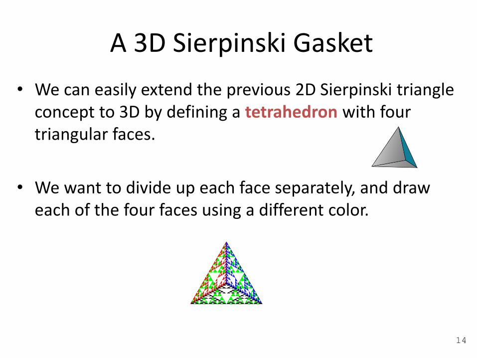
A 3D Sierpinski Gasket
• We can easily extend the previous 2D Sierpinski triangle concept to 3D by defining a tetrahedron with four triangular faces.
• We want to divide up each face separately, and draw each of the four faces using a different color.
14

A 3D Sierpinski Gasket (cont.)
• We can subdivide each of the four faces into triangles
• It appears as if we remove a solid tetrahedron from the centre, leaving four smaller tetrahedra
15

A 3D Sierpinski Gasket (cont.)
The result below is almost correct…
• Because the triangles are drawn in the order they are specified in the program, the front triangles are not always rendered in front of triangles behind them.
get this
want this
16

Hidden-Surface Removal
• We want to see only those surfaces that are in front of other surfaces
• OpenGL uses a hidden-surface removal method called the z-buffer algorithm, which saves the depth information of fragments as they are rendered so that only the front fragments appear in the image.
17

• Can hidden surface removal be done at vertex shader?
• It involves primitives, which are not formed at vertex processor.
Hidden-Surface Removal
No

The z-buffer Algorithm
The z-buffer algorithm
• is the most widely-used hidden-surface-removal algorithm
• has the advantages of being easy to implement, in either hardware or software
• is compatible with the pipeline architectures, where the algorithm can be executed at the speed at which fragments are passed through the pipeline
The algorithm works in the image space. However, it loops over the polygons rather than over pixels of the frame buffer.
19

The z-buffer algorithm – How It works
Note that 𝐩 is a point on an object in the object space
Suppose that we are in the process of rasterizing one of the two polygons shown on the right:
• We can compute a colour for each point on object (say point 𝐩)
• We must check whether 𝐩 is visible. It is visible if it is the closest point to the camera
– If we are rasterizing polygon 𝐵, then its shade will appear at that pixel on the screen, as 𝑧2 < 𝑧1
– If we are rasterizing polygon 𝐴, then its shade won’t appear at that pixel on the screen
20

The z-buffer algorithm – How It works
for each pixel (i,j) do
Z-buffer[i,j] ← FAR
Framebuffer[i,j] ← <background color>
end for
for each polygon do
for each pixel (i,j) occupied by the polygon do
Compute depth z and shade s of that polygon at (i,j)
if z > Z-buffer[i,j] then
Z-buffer[i,j] ← z
Framebuffer[i,j] ← s
end if
end for
end for
21

The z-buffer algorithm - OpenGL• The algorithm uses an extra buffer, the z-buffer, to store depth
information as geometry travels down the pipeline
• In OpenGL, the z-buffer must be:
o requested in main()
glutInitDisplayMode(GLUT_SINGLE | GLUT_RGB | GLUT_DEPTH)
o enabled in init()
glEnable(GL_DEPTH_TEST)
o cleared in the display callback
glClear(GL_COLOR_BUFFER_BIT | GL_DEPTH_BUFFER_BIT)
22
Select window with
a depth buffer

Sierpinski Gasket – After Hidden Surface Removal
23

The Painter’s Algorithm
• Although image-space methods are dominant in hardware due to the efficiency and ease of implementation of the z-buffer algorithm, often object-space methods are used in combination.
• The painter’s algorithm is an object-space approach to hidden surface removal. It is one of the simplest solutions to the visibility problem in 3D computer graphics
24
Paint
this firstPaint
this afterward
The Painter’s Algorithm (cont.)
• The name refers to the technique (employed by many painters) of painting distant parts of a scene before parts which are closer, thereby covering some areas of the distant parts.
• The algorithm sorts all the polygons in a scene by their depths. Polygons are painted from the furthest to the closest depth.
• Because of how the algorithm works, it is also known as a depth-sort algorithm.
25

The Painter’s Algorithm (cont.)
• Suppose that we have the z-extent of 5 polygons as shown on the right:– Polygon A can be painted first;
– However, we can’t determine the order for painting the other polygons
– The algorithm needs to run a number of increasingly more difficult tests in order to find the painting ordering.
(COP = centre of projection)
26

The Painter’s Algorithm (cont.)
• The simplest test is to check the x- and y-extents of the polygons:– If either of the x- or the y-extents do not
overlap, neither polygon can obscure the other. So they can be painted in any order.
• If the above test fails, can still determine the order of painting by testing if one polygon lies completely on one side of the other.
Test for overlap in the x-extents
Test for overlap in the y-extents 27
Test for all vertices on one side of the polygon

The Painter’s Algorithm (cont.)
The algorithm fails in some cases, including
• Polygons that pierce (intersect) each other
• Polygons that form a cycle of depth overlap
28
Cyclic overlapPiercing polygons
Double Buffering
• Availability of uniform variable type opens the door to animation:– We can call glUniform in the display callback
– We can then force a redraw through glutPostRedisplay()
This is particularly useful when the application deals with 3D objects
29
Double Buffering (cont.)
• To animate a scene smoothly, we need to prevent a partially redrawn frame buffer from being displayed.
• A way to prevent the above issue from happening is to use double buffering – i.e., we request two buffers:
– While drawing is performed on the back buffer, the front buffer is being displayed
– Swap buffers after the update on the back buffer is finished
30

Adding Double Buffering
• Request a double buffer
– glutInitDisplayMode(GLUT_DOUBLE)
• Swap buffersvoid mydisplay()
{
glClear(……);
glDrawArrays(…);
glutSwapBuffers();
}
31

Element Buffers
• Complex 3D models have thousands of triangles
• We can re-use the vertices while defining triangles (for efficiency)
• GL_ELEMENT_ARRAY_BUFFER is used for this
• Lab 5, q4aIndex.cpp draws a cube by specifying only 8 vertices
• 8 vertices -> 6 squares -> 12 triangles
32
3D Model File Format
• 3D model file formats follow a similar convention i.e.
– A list of vertices as floats (x, y, z)
– A list of elements as integers specifying which vertices connect to form a triangle
• Sometimes the vertex normals are also provided as floats
33

Some 3D File Extensions
• PLY files have *.ply extension
• VRML files have a *.wrl extension
• 3D Studio files have a *.3ds extension
• Blender files have a *.blend extension
• Object files have a *.obj extension
• DirectX files have a *.x extension

The PLY format
ply
format ascii 1.0
comment zipper output
element vertex 28980
property float x
property float y
property float z
element face 56207
property list uchar int vertex_indices
end_header
44968.501119 -43787.362630 83846.209031
46090.448700 -44321.044193 81938.091386
39593.486637 -49592.734508 86290.454426
46243.264772 -42401.503638 83047.168327
45096.493171 -42006.610299 84810.068897
.
.
3 24028 24504 24620
3 20691 20688 20755
3 19350 19371 19384
3 942 377 1297
If you open a *.ply file in wordpad
You see this
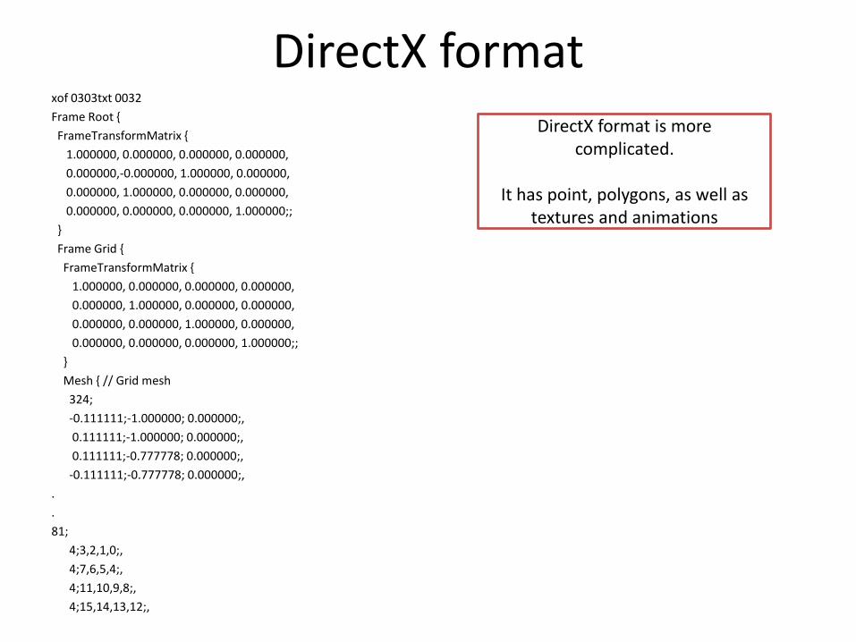
DirectX formatxof 0303txt 0032
Frame Root {
FrameTransformMatrix {
1.000000, 0.000000, 0.000000, 0.000000,
0.000000,-0.000000, 1.000000, 0.000000,
0.000000, 1.000000, 0.000000, 0.000000,
0.000000, 0.000000, 0.000000, 1.000000;;
}
Frame Grid {
FrameTransformMatrix {
1.000000, 0.000000, 0.000000, 0.000000,
0.000000, 1.000000, 0.000000, 0.000000,
0.000000, 0.000000, 1.000000, 0.000000,
0.000000, 0.000000, 0.000000, 1.000000;;
}
Mesh { // Grid mesh
324;
-0.111111;-1.000000; 0.000000;,
0.111111;-1.000000; 0.000000;,
0.111111;-0.777778; 0.000000;,
-0.111111;-0.777778; 0.000000;,
.
.
81;
4;3,2,1,0;,
4;7,6,5,4;,
4;11,10,9,8;,
4;15,14,13,12;,
DirectX format is more complicated.
It has point, polygons, as well as textures and animations

Further Reading
“Interactive Computer Graphics – A Top-Down Approach with Shader-Based OpenGL” by Edward Angel and Dave Shreiner, 6th Ed, 2012
• Sec. 2.10.3 Hidden-Surface Removal (pages 96-98)
• Sec. 4.8 Hidden-Surface Removal (pages 239-241)
• Sec. 6.11.5 The Z-Buffer Algorithm (pages 335-338)
• Sec. 6.11.7 Depth Sort and the Painter’s Algorithm (pages 340-342)
37