lecture 10.2: basics elements of a navigational program...
TRANSCRIPT
Lecture 10.2:
Basics Elements of a Navigational Program:Orbit Determination and Parameter Estimation
Курс Лекций: «Современные Проблемы Астрономии»для студентов Государственного Астрономического Института им. П.К. Штернберга
7 февраля – 23 мая 2011
В. Г. Турышев Jet Propulsion Laboratory, California Institute of Technology
4800 Oak Grove Drive, Pasadena, CA 91009 USAГосударственный Астрономический Институт им. П.К. Штернберга
Университетский проспект, дом 13, Москва, 119991 Россия

ORBIT DETERMINATION AND PARAMETER ESTIMATIONORBIT DETERMINATION AND PARAMETER ESTIMATION
Wizardry of Spacecraft Navigation

ORBIT DETERMINATION AND PARAMETER ESTIMATIONORBIT DETERMINATION AND PARAMETER ESTIMATION
Earth
Mars
Sun
Radio Metric Tracking
Solar Torques,Thruster Firings
Guidance Commands
Observations
Flight-PathOptimization
Data FitOK?
Compare
DynamicModels
Observational Models
Predicted Observations
No
Yes
Flight PathEstimation
Ground Data Processing System
Planetary Ephemerides
CalibrationsEarth Rotation
Station Locations
Functions: Measurement Acquisition, Flight Path Determination, Maneuver Computation and Command
Deep Space Navigation System
ORBIT DETERMINATION AND PARAMETER ESTIMATIONORBIT DETERMINATION AND PARAMETER ESTIMATION
Parameter Estimation
Trajectory Propagation
Initial Parameter Values
Updated Parameters
Comparison
Observational Model
Real Observations(Radio Metric and Optical)
Predicted Observations
Predicted Flight Path
Residuals
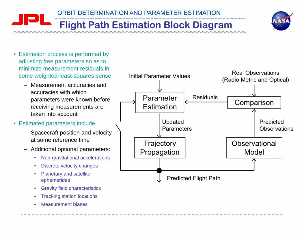
Flight Path Estimation Block Diagram
• Estimation process is performed by adjusting free parameters so as to minimize measurement residuals in some weighted-least-squares sense
– Measurement accuracies and accuracies with which parameters were known before receiving measurements are taken into account
• Estimated parameters include– Spacecraft position and velocity
at some reference time– Additional optional parameters:
• Non-gravitational accelerations• Discrete velocity changes• Planetary and satellite
ephemerides• Gravity field characteristics• Tracking station locations• Measurement biases
ORBIT DETERMINATION AND PARAMETER ESTIMATIONORBIT DETERMINATION AND PARAMETER ESTIMATION
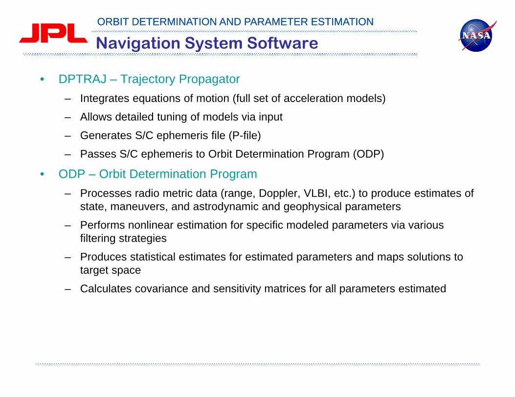
Navigation System Software
• DPTRAJ – Trajectory Propagator– Integrates equations of motion (full set of acceleration models)
– Allows detailed tuning of models via input
– Generates S/C ephemeris file (P-file)
– Passes S/C ephemeris to Orbit Determination Program (ODP)
• ODP – Orbit Determination Program– Processes radio metric data (range, Doppler, VLBI, etc.) to produce estimates of
state, maneuvers, and astrodynamic and geophysical parameters
– Performs nonlinear estimation for specific modeled parameters via various filtering strategies
– Produces statistical estimates for estimated parameters and maps solutions to target space
– Calculates covariance and sensitivity matrices for all parameters estimated
ORBIT DETERMINATION AND PARAMETER ESTIMATIONORBIT DETERMINATION AND PARAMETER ESTIMATION
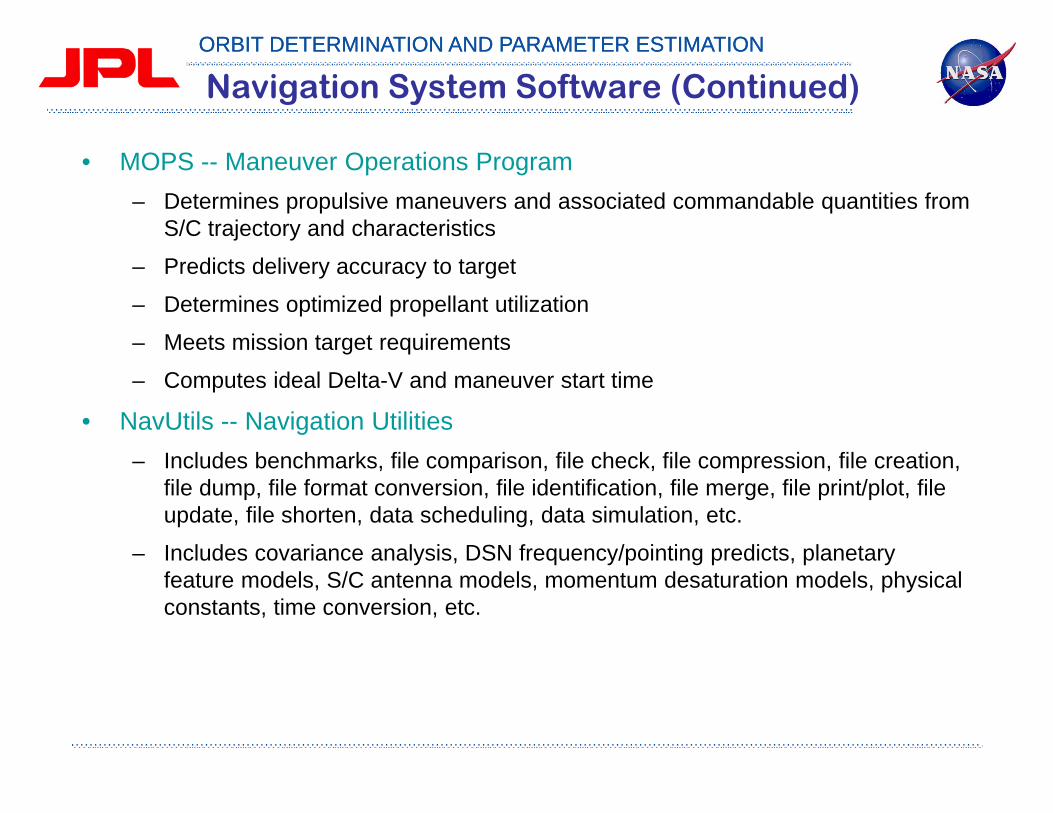
Navigation System Software (Continued)
• MOPS -- Maneuver Operations Program– Determines propulsive maneuvers and associated commandable quantities from
S/C trajectory and characteristics
– Predicts delivery accuracy to target
– Determines optimized propellant utilization
– Meets mission target requirements
– Computes ideal Delta-V and maneuver start time
• NavUtils -- Navigation Utilities– Includes benchmarks, file comparison, file check, file compression, file creation,
file dump, file format conversion, file identification, file merge, file print/plot, file update, file shorten, data scheduling, data simulation, etc.
– Includes covariance analysis, DSN frequency/pointing predicts, planetary feature models, S/C antenna models, momentum desaturation models, physical constants, time conversion, etc.

ORBIT DETERMINATION AND PARAMETER ESTIMATIONORBIT DETERMINATION AND PARAMETER ESTIMATION
Navigation System Software (Continued)
• NavLibs – Navigation Libraries– ~ 70 libraries– ~ 4000 subroutines– ~ 750,000 LOC (FORTRAN 77)– Portable
• All Use NAVSYS
– Reusable• Shared throughout system and among users
• NAVSYS Library -- System Dependent Functions – Colocates all computing system dependent features– Isolates system dependent features to single library on which
other modules depend– Uses common IEEE definition for errors/exceptions
• Numerous other programs and modules not listed above
ORBIT DETERMINATION AND PARAMETER ESTIMATIONORBIT DETERMINATION AND PARAMETER ESTIMATION
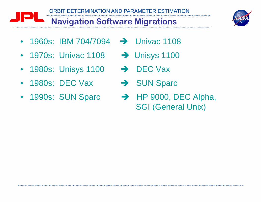
Navigation Software Migrations
• 1960s: IBM 704/7094 Univac 1108
• 1970s: Univac 1108 Unisys 1100
• 1980s: Unisys 1100 DEC Vax
• 1980s: DEC Vax SUN Sparc
• 1990s: SUN Sparc HP 9000, DEC Alpha, SGI (General Unix)

ORBIT DETERMINATION AND PARAMETER ESTIMATIONORBIT DETERMINATION AND PARAMETER ESTIMATION
Spacecraft Dynamics
• Equations of motion
• Gravitational accelerations– Static & time varying gravitational field of the PCB– Third body perturbations– One-body relativistic perturbations
• Non-gravitational accelerations– Atmospheric drag, solar radiation, PCB radiation– Spacecraft thruster firing, gas leaks, maneuvers
r = A grav + A non-grav

ORBIT DETERMINATION AND PARAMETER ESTIMATIONORBIT DETERMINATION AND PARAMETER ESTIMATION
Measurement Models for DSN Tracking Data
• Observed & computed 2-way range observables
• Observed & computed 2-way Doppler observables
• Location of the DSN station in Earth-fixed coordinates
oup+down = c t + tropo
up+down + ionoup+down +
c = rsc - rsta phaseup + rsc - rsta phase
down + relup +down + bias
o = cft
(N12-Ntrop -Niono )(t2 - t1)
- +
rsta = rmarker + Splate + Sphase + Sdtide + Spole + Sload
c = 1t2 - t1
c + rel + cftf

ORBIT DETERMINATION AND PARAMETER ESTIMATIONORBIT DETERMINATION AND PARAMETER ESTIMATION
Parameter Estimation: Simplified Form
• State equations
• Liberalized state equations
• Observation equations
• Linearized observation equations
0( , ) ( ) ; ( ) ( ) ( )
X
F X tx x x t x x t X t X tX
*
0*
*0 0( , ); ( )X F X t X t X
**
j 0
( , )( , ) + j j
j j j j j j j
X
G X ty Y G X t x H x
X
*
1( , ) ; [ ] 0; [ ]Tj j j j j i j ij j jY G X t E E f R

ORBIT DETERMINATION AND PARAMETER ESTIMATIONORBIT DETERMINATION AND PARAMETER ESTIMATION
ODP Processing Flowchart

ORBIT DETERMINATION AND PARAMETER ESTIMATIONORBIT DETERMINATION AND PARAMETER ESTIMATION
ORBIT DETERMINATION AND PARAMETER ESTIMATIONORBIT DETERMINATION AND PARAMETER ESTIMATION
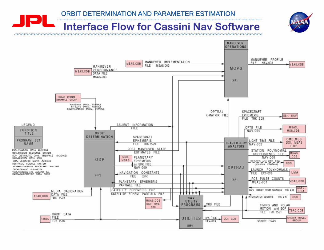
Interface Flow for Cassini Nav Software

ORBIT DETERMINATION AND PARAMETER ESTIMATIONORBIT DETERMINATION AND PARAMETER ESTIMATION
Context: The Goal of OD?
• Take an enormous amount of input data and reduce it to manageable, usable, and comprehensible form, i.e., plots, readable summaries, Navio files, etc.
The finest solutions in the world are only random numbers, if you cannot comprehend them. — Anatole France
ORBIT DETERMINATION AND PARAMETER ESTIMATIONORBIT DETERMINATION AND PARAMETER ESTIMATION
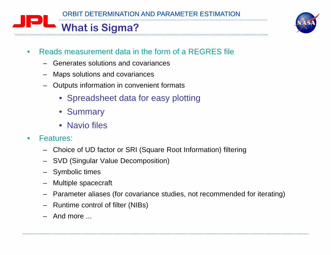
What is Sigma?
• Reads measurement data in the form of a REGRES file– Generates solutions and covariances– Maps solutions and covariances– Outputs information in convenient formats
• Spreadsheet data for easy plotting• Summary• Navio files
• Features:– Choice of UD factor or SRI (Square Root Information) filtering– SVD (Singular Value Decomposition)– Symbolic times– Multiple spacecraft– Parameter aliases (for covariance studies, not recommended for iterating)– Runtime control of filter (NIBs)– And more ...

ORBIT DETERMINATION AND PARAMETER ESTIMATIONORBIT DETERMINATION AND PARAMETER ESTIMATION
Context of Sigma Relationships
A rather complex maze of relationships – all for one goal to make it simple!
ORBIT DETERMINATION AND PARAMETER ESTIMATIONORBIT DETERMINATION AND PARAMETER ESTIMATION
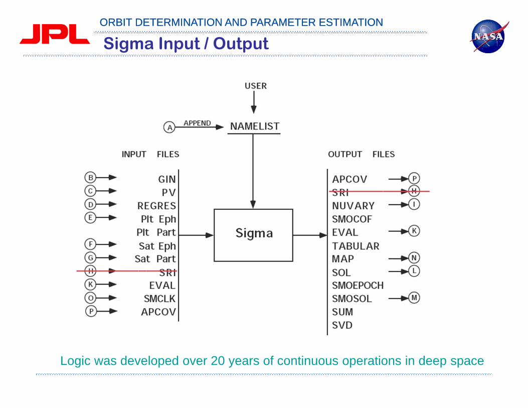
Sigma Input / Output
Logic was developed over 20 years of continuous operations in deep space

ORBIT DETERMINATION AND PARAMETER ESTIMATIONORBIT DETERMINATION AND PARAMETER ESTIMATION

ORBIT DETERMINATION AND PARAMETER ESTIMATIONORBIT DETERMINATION AND PARAMETER ESTIMATION
• Generate or Acquire Trajectory – Generating the satellite's trajectory involves calculating an initial
solution based on a priori estimates of the forces acting on the satellite. – From the initial solution, an iteration of the trajectory based on updated
partials and observables creates an ephemeris within the required tolerances.

ORBIT DETERMINATION AND PARAMETER ESTIMATIONORBIT DETERMINATION AND PARAMETER ESTIMATION
Processing Radiometric Data
Pre-processing (Editing Orbit Datafiles)
Generate or Acquire Trajectory

ORBIT DETERMINATION AND PARAMETER ESTIMATIONORBIT DETERMINATION AND PARAMETER ESTIMATION
Attitude Model and Input

ORBIT DETERMINATION AND PARAMETER ESTIMATIONORBIT DETERMINATION AND PARAMETER ESTIMATION
Solar Radiation Pressure

ORBIT DETERMINATION AND PARAMETER ESTIMATIONORBIT DETERMINATION AND PARAMETER ESTIMATION
Solar Radiation Pressure Input
ORBIT DETERMINATION AND PARAMETER ESTIMATIONORBIT DETERMINATION AND PARAMETER ESTIMATION
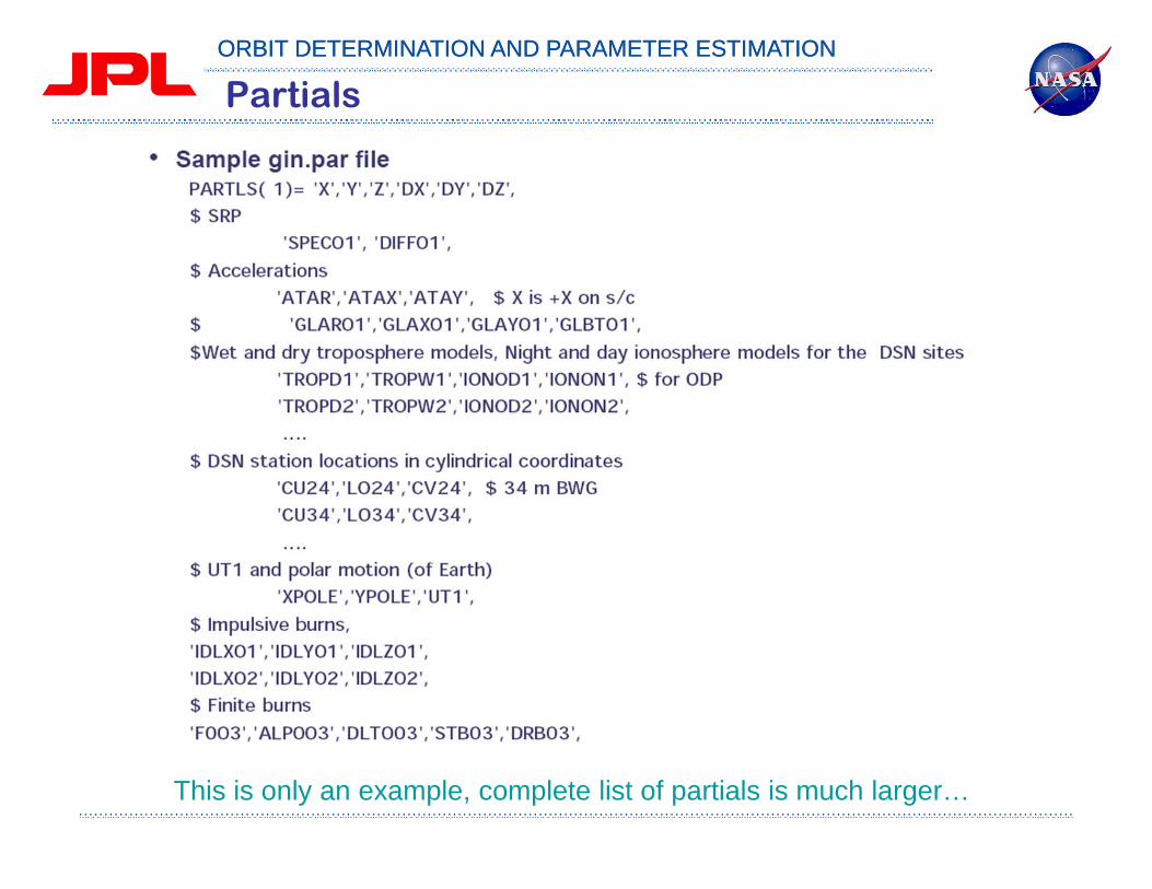
Partials
This is only an example, complete list of partials is much larger…

ORBIT DETERMINATION AND PARAMETER ESTIMATIONORBIT DETERMINATION AND PARAMETER ESTIMATION
Dynamic Input

ORBIT DETERMINATION AND PARAMETER ESTIMATIONORBIT DETERMINATION AND PARAMETER ESTIMATION
Dynamic Input Example

ORBIT DETERMINATION AND PARAMETER ESTIMATIONORBIT DETERMINATION AND PARAMETER ESTIMATION
Small Forces File. The P- and PV-files

ORBIT DETERMINATION AND PARAMETER ESTIMATIONORBIT DETERMINATION AND PARAMETER ESTIMATION
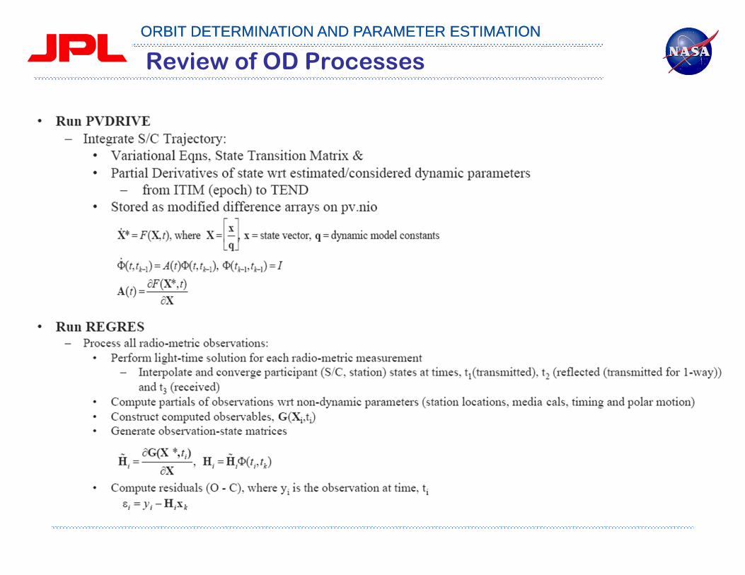
• Computed Observables:– Using PVDRIVE data, ODF and CSP inputs, run REGRES to produce a file of
observables, and all data partials of observables, at specified times. – The observables and partials are with respect to estimated (solve for)
parameters and regression partials, using the nominal or reference trajectory.
Processing Radiometric DataODMerge

ORBIT DETERMINATION AND PARAMETER ESTIMATIONORBIT DETERMINATION AND PARAMETER ESTIMATION
Processing Differenced
Data
Processing Optical Data
Merging and Modifying
Data

ORBIT DETERMINATION AND PARAMETER ESTIMATIONORBIT DETERMINATION AND PARAMETER ESTIMATION
Major Inputs to the ‘Regres’ Software
• Earth Orientation File– Earth Orientation Parameters File (EOP) by the Kalman Earth
Orientation Filter (KEOF).
– Used to tie the measurements recorded at the tracking stations in the International Earth Rotation Service (IERS) terrestrial ref frame (ITRF93) to the celestial ref (radio) frame (ICRF93).
• What is it?– Gin inputs for Earth’s orientation in the ICRF93 frame. Contains:
• x, y polar motion updates (milliarcseconds),
• TAI - UT1 (sec), TAI - UTC (sec)
• nutation corrections (milliarcseconds)
– One file for all missions, all DSN stations

ORBIT DETERMINATION AND PARAMETER ESTIMATIONORBIT DETERMINATION AND PARAMETER ESTIMATION
Major Inputs to the ‘Regres’ Software
• Media Calibrations: – Ionospheric & Tropospheric Calibrations are computed by the Tracking
System Analytic Calibration (TSAC) group.– Used to calibrate radio metric data (Doppler, Range, DDOR) using
measurements of media based on GPS survey at DSN complexes.• What is it?
– Individual files of coefficients written for each month that describe radio signal delay as a function of time in meters
– Troposphere/Zenith delay coefficients• Seasonal (Trigonometric, wet and dry, good for all missions/time)• Station Altitude (Constant, dry, 1 per station, good for all missions/time)• Seasonal Correction Delay (Normalized power series, wet and dry, 1 per
complex, good for all missions)• Made with weather data from the complexes and GPS data
– Ionosphere delay coefficients (Normalized power series)• Doppler/range (1 per complex per spacecraft per pass)• Delta-DOR (1 per complex per observation sequence)• Made with GPS data

ORBIT DETERMINATION AND PARAMETER ESTIMATIONORBIT DETERMINATION AND PARAMETER ESTIMATION
Tropospheric Delay example

ORBIT DETERMINATION AND PARAMETER ESTIMATIONORBIT DETERMINATION AND PARAMETER ESTIMATION
Major Inputs to the ‘Regres’ Software
• Station Locations– Used to relate data received at Deep Space Station antennas to S/C
ephemeris (position, velocity) given with respect to some center of integration. Covariance used to apply station location errors OD filter estimates.
• What are they?– Gin namelist inputs of
• all DSN stations in cylindrical coordinates relative to the ITRF93 frame,• also includes all pertinent station complex parameters: i) antenna offsets,
ii) linear plate motion parameters, iii) horizon masks,• regres model inputs (STNMOD)
– solid tides, pole tide, ocean loading, polar motion, plate motion, ET-TAI vector conversion, etc
– Gin namelist inputs for ‘old ODP filter’ for• Correlated cylindrical position covariance for all DSN stations• Need to be converted to newer sigma inputs

ORBIT DETERMINATION AND PARAMETER ESTIMATIONORBIT DETERMINATION AND PARAMETER ESTIMATION
Major Inputs to the ‘Regres’ Software
• Orbit data files (ODFs) or Tracking data files– Used as observables for determining S/C ephemeris using least
squares filter.• 1,2,3-way Doppler, 2-way -3-way Doppler, SRA ranging, DDOR, optical,
etc
• What is it?– Bit-packed files with tracking data observables (all data types) and
some relevant ancillary information• Time, Data type, Bands, Station participants, Reference frequencies, etc.
• Built from DSN data, along with configuration information from complexes
– Note: Most navigators convert ODFs directly to the NAVIO Tracking Data File (NTDF) using ‘odfconvrt’ and use ODP tools to compress, inspect, change, etc.

ORBIT DETERMINATION AND PARAMETER ESTIMATIONORBIT DETERMINATION AND PARAMETER ESTIMATION
Tracking Data Types (1)
• One-way doppler (F1)– F1 measurements are made when the S/C is the source of the signal’s reference frequency.
The frequency reference is usually provided by an auxiliary oscillator or an ultra-stable oscillator (USO). The signal frequency is doppler shifted on the downleg path.
– Measures the line-of-sight component of the S/C velocity– F1 is prone to irregular biases and ramps– Units in the ODP are in hertz (Hz)– 1 Hz = 35.6 mm/s for X-band downlink
• Two-way coherent doppler (F2)– F2 measurements are made when a single tracking station radiates a signal to a S/C which in
turn multiplies the received signal by a constant (turn-around ratio) and sends the signal back to the transmitting station. The signal frequency is Doppler shifted on both the upleg and downleg paths.
– Measures the line-of-sight component of the S/C velocity– Units in the ODP are in hertz (Hz)– 1 Hz = 17.8 mm/s for X-band uplink/downlink
• Ranging (SRA)– Range observations are obtained at a single tracking station by measuring the time delay
between the transmission and reception of a ranging signal– Measures the line-of-sight component of the S/C position– Units in the ODP are “range units” or RUs– 1 RU = 0.142 meter– SRA is an acronym for Sequential Ranging Assembly
ORBIT DETERMINATION AND PARAMETER ESTIMATIONORBIT DETERMINATION AND PARAMETER ESTIMATION
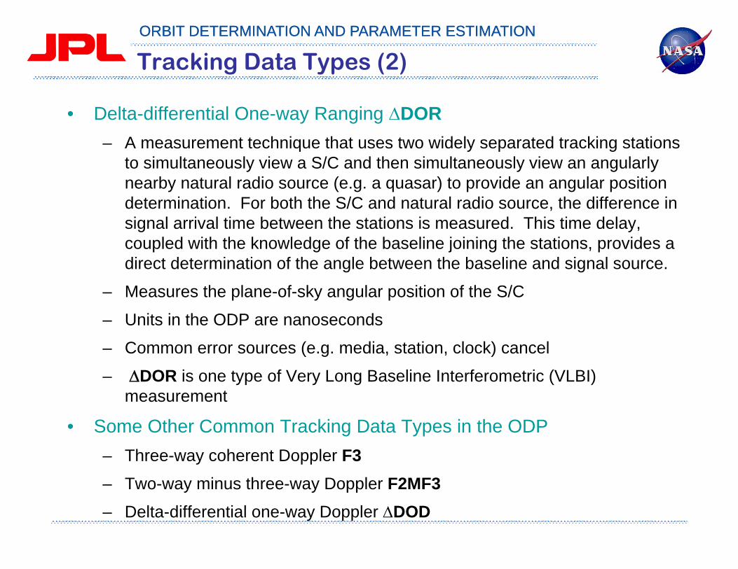
Tracking Data Types (2)
• Delta-differential One-way Ranging DOR– A measurement technique that uses two widely separated tracking stations
to simultaneously view a S/C and then simultaneously view an angularly nearby natural radio source (e.g. a quasar) to provide an angular position determination. For both the S/C and natural radio source, the difference in signal arrival time between the stations is measured. This time delay, coupled with the knowledge of the baseline joining the stations, provides a direct determination of the angle between the baseline and signal source.
– Measures the plane-of-sky angular position of the S/C
– Units in the ODP are nanoseconds
– Common error sources (e.g. media, station, clock) cancel
– DOR is one type of Very Long Baseline Interferometric (VLBI) measurement
• Some Other Common Tracking Data Types in the ODP– Three-way coherent Doppler F3– Two-way minus three-way Doppler F2MF3– Delta-differential one-way Doppler DOD

ORBIT DETERMINATION AND PARAMETER ESTIMATIONORBIT DETERMINATION AND PARAMETER ESTIMATION
• Estimate – Residual data editing may be necessary. The raw tracking data may exhibit
corrupt data points or anomalies that should not be included in the final solution.
– If the residual values do not fall within the expected tolerances, then the CSP file may be used to exclude the questionable data during the next REGRES run.
ORBIT DETERMINATION AND PARAMETER ESTIMATIONORBIT DETERMINATION AND PARAMETER ESTIMATION
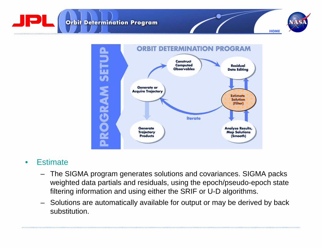
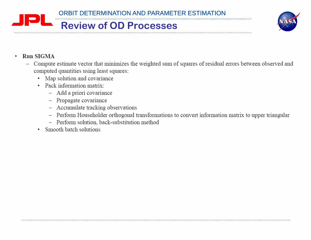
• Estimate – The SIGMA program generates solutions and covariances. SIGMA packs
weighted data partials and residuals, using the epoch/pseudo-epoch state filtering information and using either the SRIF or U-D algorithms.
– Solutions are automatically available for output or may be derived by back substitution.

ORBIT DETERMINATION AND PARAMETER ESTIMATIONORBIT DETERMINATION AND PARAMETER ESTIMATION
• Analyze Data – SIGMA maps the solutions and their associated data as well as landmarks and
the spacecraft, planet, and satellite ephemerides and their partials, are mapped forward or backward in time to a variety of coordinate sets.
– The mapping function uses the filter model of the dynamic process noise to properly reflect the modeled stochastic effects, while mapping either forward beyond the end of a data arc, or back into its interior.
ORBIT DETERMINATION AND PARAMETER ESTIMATIONORBIT DETERMINATION AND PARAMETER ESTIMATION
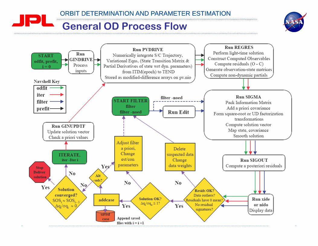
General OD Process Flow
ORBIT DETERMINATION AND PARAMETER ESTIMATIONORBIT DETERMINATION AND PARAMETER ESTIMATION
Review of OD Processes
ORBIT DETERMINATION AND PARAMETER ESTIMATIONORBIT DETERMINATION AND PARAMETER ESTIMATION
Review of OD Processes

ORBIT DETERMINATION AND PARAMETER ESTIMATIONORBIT DETERMINATION AND PARAMETER ESTIMATION
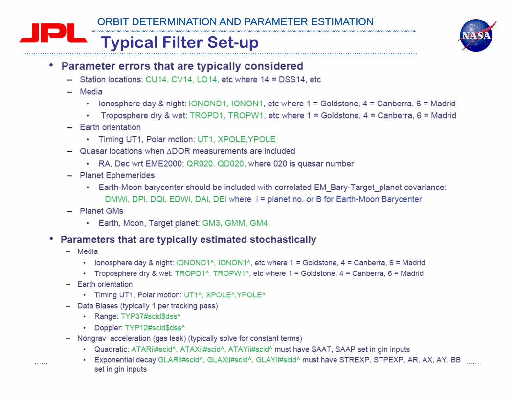
Typical Filter Set-up
ORBIT DETERMINATION AND PARAMETER ESTIMATIONORBIT DETERMINATION AND PARAMETER ESTIMATION
Typical Filter Set-up
ORBIT DETERMINATION AND PARAMETER ESTIMATIONORBIT DETERMINATION AND PARAMETER ESTIMATION
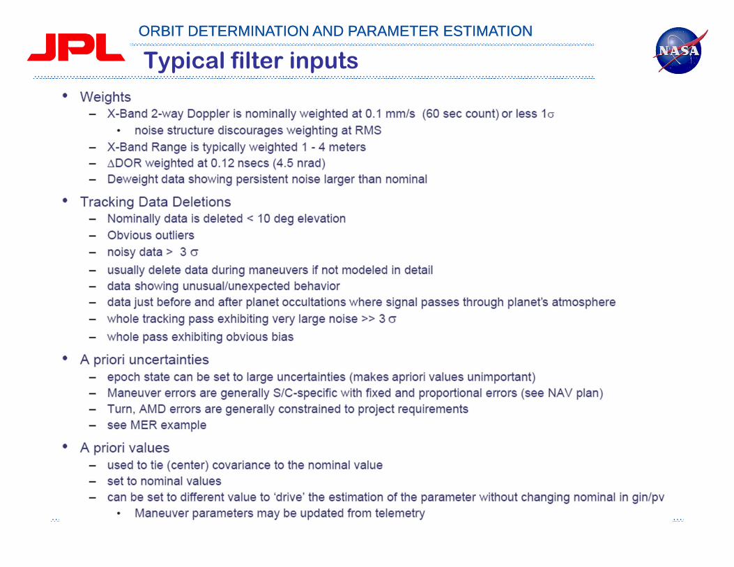
Typical filter inputs

ORBIT DETERMINATION AND PARAMETER ESTIMATIONORBIT DETERMINATION AND PARAMETER ESTIMATION
Typical stochastic parameters
ORBIT DETERMINATION AND PARAMETER ESTIMATIONORBIT DETERMINATION AND PARAMETER ESTIMATION
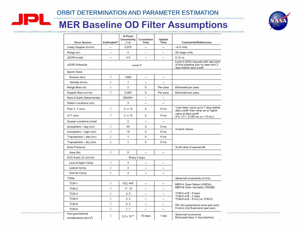
MER Baseline OD Filter Assumptions
ORBIT DETERMINATION AND PARAMETER ESTIMATIONORBIT DETERMINATION AND PARAMETER ESTIMATION
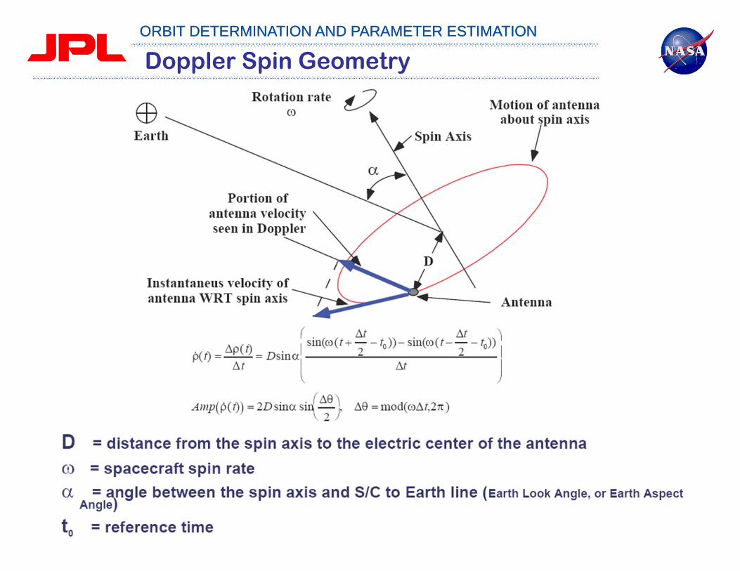
Doppler Spin Geometry

ORBIT DETERMINATION AND PARAMETER ESTIMATIONORBIT DETERMINATION AND PARAMETER ESTIMATION
Doppler Spin Signatures

ORBIT DETERMINATION AND PARAMETER ESTIMATIONORBIT DETERMINATION AND PARAMETER ESTIMATION
Examples of Doppler Spin Signatures

ORBIT DETERMINATION AND PARAMETER ESTIMATIONORBIT DETERMINATION AND PARAMETER ESTIMATION
Genesis SKM-2B Doppler Prefit Residual
ORBIT DETERMINATION AND PARAMETER ESTIMATIONORBIT DETERMINATION AND PARAMETER ESTIMATION
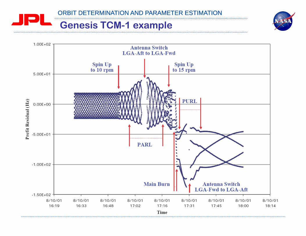
Genesis TCM-1 example
ORBIT DETERMINATION AND PARAMETER ESTIMATIONORBIT DETERMINATION AND PARAMETER ESTIMATION
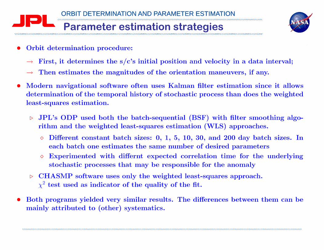
Parameter estimation strategies

ORBIT DETERMINATION AND PARAMETER ESTIMATIONORBIT DETERMINATION AND PARAMETER ESTIMATION
Error Source Current Modeling Accuracy
Station LocationsCrust-relative …….………….………….……….……... 5 cmPole location …….………….………….………..……... 5 cmTiming (UTC) ….………….………….…………...……. 0.5 ms
MediaIonosphere (X-Band, 8.4 GHz) ….………….……...… 5 cmTroposphere .………….………….……………….....… 4 cm
Ground InstrumentationStation oscillator .………….………….……….…....… 10-14
Hardware range delays .………..….………….……… 0.5 - 1 m
DynamicsNon-gravitational acceleration of spacecraft …...… 10-12 - 10-11 km/s2
Principal Error Sources in Radio Navigation

ORBIT DETERMINATION AND PARAMETER ESTIMATIONORBIT DETERMINATION AND PARAMETER ESTIMATION
BUCK-UP SLIDES
ORBIT DETERMINATION AND PARAMETER ESTIMATIONORBIT DETERMINATION AND PARAMETER ESTIMATION
Orbit Determination
• Determination of the state of orbiting objects whose motion can be described approximately by a set of equations of motion and monitored by discrete observations which are subject to both random and systematic errors– Time systems– Coordinate systems– Spacecraft force models– Tracking measurement models– Parameter estimation

ORBIT DETERMINATION AND PARAMETER ESTIMATIONORBIT DETERMINATION AND PARAMETER ESTIMATION
Space Geodesy
• Solve the geodetic problems by the use of precise measurements to, from or between spacecrafts to– determine the site position/velocity to define the terrestrial
reference frame;– determine the gravitational constant of the PCB;– determine the gravity field of the PCB;– determine of secular and tidal variations of the gravity field of the
PCB;– determine the orientation of the PCB.

ORBIT DETERMINATION AND PARAMETER ESTIMATIONORBIT DETERMINATION AND PARAMETER ESTIMATION
Reference Systems
• Time Systems– Sidereal time & universal time: time scales directly related to the
Earth rotation– TAI & UTC: atomic time scales– TDT & TDB: dynamical time scales
• Coordinate Systems– J2000.0 barycentric & geocentric reference frames– Body-fixed terrestrial reference frame of Earth & PCB

ORBIT DETERMINATION AND PARAMETER ESTIMATIONORBIT DETERMINATION AND PARAMETER ESTIMATION
Parameter Leveling for Space Geodesy Application
• Local parameter– S/C dependent arc parameters
• Global parameter– GM’s
– Spherical harmonics of the gravity field model
– Love number of the solid tides
– Parameters of the rotation model
– Planetary/satellite/small body ephemeris

ORBIT DETERMINATION AND PARAMETER ESTIMATIONORBIT DETERMINATION AND PARAMETER ESTIMATION
Solution Strategy for Space Geodesy Application
• Compute reference orbits for each data arc (batch filter).– Adjust nominal value for arc dependent parameters.– Fix nominal value for global parameters.
• Generate SRIF equations of arc and global parameters for each data arc using converged reference orbits.
• Merge SRIF equations of global parameters from grouped data arcs for each spacecraft.
• Combine the SRIF equations derived from all orbiting spacecrafts.– Apply the empirical apriori information equations for estimated
parameters.– Determine the relative data weight for each of the SRIF
equations to take into consideration of measurement and dynamic model errors.