lecture 1 - filters and time response
TRANSCRIPT

7/30/2019 Lecture 1 - Filters and Time Response
http://slidepdf.com/reader/full/lecture-1-filters-and-time-response 1/13
MEM 640 Lecture 1: Filters and Time Response

7/30/2019 Lecture 1 - Filters and Time Response
http://slidepdf.com/reader/full/lecture-1-filters-and-time-response 2/13
Filters: Why Study Them?
RCVi oV
• Low Pass Filter is a classic first-order system• Easily assembled for experimentation• Differential equations are easy to derive: time domain• Frequency domain easy to derive• Show duality: time and frequency domain

7/30/2019 Lecture 1 - Filters and Time Response
http://slidepdf.com/reader/full/lecture-1-filters-and-time-response 3/13

7/30/2019 Lecture 1 - Filters and Time Response
http://slidepdf.com/reader/full/lecture-1-filters-and-time-response 4/13
Integrating Equation (3) yields:
11ln K t
RC V +−= Where 1K is a constant
Or
RC t o
K RC t eV eet V / / 1)( −− == Where oV is a constant (4)
RCt [sec]
Vo
Vo0.37
Plot of Equation (3) looks like:
Suppose RC t = then (3) yields: oo V eV RC V 37.0)(1
==−
At oo V eV RC V 05.0)3( 3 == −Engineers call the 95% value 3 time constants

7/30/2019 Lecture 1 - Filters and Time Response
http://slidepdf.com/reader/full/lecture-1-filters-and-time-response 5/13
Slightly Different Scenario
RCVi oV
Case Study: What is the voltage across the capacitor when the switch is closed?
The equation for this circuit is: R
V V dt
dV C I oio −≡= where iV is constant (5)
Then ( ) RC V
RC V
V V RC dt
dV oioi
o −=−= 1 (6)
The solution to the non-homogeneous differential equation (6) is:
RC t io AeV t V / )( −+= (7)
Given that 0)0( =oV then iV A −= and the solution to (7) becomes
)1()(/ RC t
io eV t V −
−=(8)
7/30/2019 Lecture 1 - Filters and Time Response
http://slidepdf.com/reader/full/lecture-1-filters-and-time-response 6/13
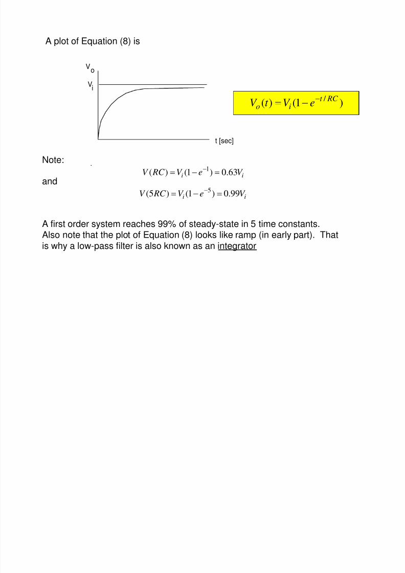
A plot of Equation (8) is
)1()( / RC t
ioeV t V −−=
t [sec]
Vi
Vo
Note:ii V eV RC V 63.0)1()( 1 =−= −
ii V eV RC V 99.0)1()5( 5 =−= −and
A first order system reaches 99% of steady-state in 5 time constants.Also note that the plot of Equation (8) looks like ramp (in early part). Thatis why a low-pass filter is also known as an integrator

7/30/2019 Lecture 1 - Filters and Time Response
http://slidepdf.com/reader/full/lecture-1-filters-and-time-response 7/13
Laplace Domain: Insights into Frequency Response
From (8) we derived the time response for a low pass filter as:
)1()( at io eV t V −−= where say
RC a
1= (9)
Taking Laplace transform of (9) yields
)()( assaV ii
oi
asV
sV
sV +=+
−= (10)
Now since iV Is a step input, recognize that
sV
asa
sV io +
=)(
Actual transferfunction
Step inputcontribution
Thus transfer function for a low pass filter is given as
asa
V V
i
o
+=(11)

7/30/2019 Lecture 1 - Filters and Time Response
http://slidepdf.com/reader/full/lecture-1-filters-and-time-response 8/13
as
a
V
V
i
o
+=
We will see later that the Bode Plot for (11) looks like
dB
frequency
-20 dB/decade slope
cutoff frequency
-3 dB
Recall that xdB log20= thus at -3 dB we have 707.010 20 / 3 == − x
Also recall from (8) that one time constant yields 63.3% of steady state
Thus the cutoff frequency is approximately the system’s time constant value
Also note that ( ) 499.0707.0 2 =
Power is proportional to voltage squared. Hence the -3 dB point represents
a 50% drop in power

7/30/2019 Lecture 1 - Filters and Time Response
http://slidepdf.com/reader/full/lecture-1-filters-and-time-response 9/13
Where are we going with this?
Problem: Show mathematically, the integrative properties of the LP filter
RCVi oV
Solution: The voltage across the resistor is oi V V − So:
R
V V
dt
dV C I oio −≡= (12)
Now suppose that io V V << then (12) can be re-expressed as
RV
dt dV
C ino ≈ (13)
Or,∫ ∫ +==
t
iin
o dt t V RC
dt RC V
t V constant)(1
)( (14)
The approximation (13) says the current is proportional to iV
. If iV is largeand is large, then we have a current source. R
Integration!

7/30/2019 Lecture 1 - Filters and Time Response
http://slidepdf.com/reader/full/lecture-1-filters-and-time-response 10/13
Hi Pass Filters Perform DerivativesProblem: Show that a hi pass filter perform differentiation
RCVi oV
Solution: The voltage across the cap is so we haveoi V V −
( ) R
V V V
dt
d C
dt
dV C I o
oi ≡−== (15)
Now if and chosen small enough so that R C
dt dV
dt dV oi >> (16)
Then R
V
dt
dV C oi ≈ (17)
Derivative!
Hencedt
dV RC V i
o = (18)

7/30/2019 Lecture 1 - Filters and Time Response
http://slidepdf.com/reader/full/lecture-1-filters-and-time-response 11/13
Grandmother Explanation

7/30/2019 Lecture 1 - Filters and Time Response
http://slidepdf.com/reader/full/lecture-1-filters-and-time-response 12/13
Based on Target Dynamics
• Shooter adds angle theta
• Adds phase
• Shooter angle LEADS target angle• Compensation
• Derivatives: rate of change
• Ignore high frequencies (hi-pass)
Differentiation LEAD compensation Hi-Pass Filter≈ ≈

7/30/2019 Lecture 1 - Filters and Time Response
http://slidepdf.com/reader/full/lecture-1-filters-and-time-response 13/13