lecture – 1 design philosophy · working stress method of design ... limit state method of design...
TRANSCRIPT

Lecture – 1
Design Philosophy Working Stress Method of Design Concrete is strong in compression and crushing strength is determined by test on standard cubes. Large deformation is noticed at the failure load. Deformation is permanent in nature. This suggests for the adoption of a factor of safety. Permissible bending & direct compression are as fraction of crushing strength. For example: M15 concrete, the value of cbcσ = 5 = (15/3) and ccσ = 4 = (15/3.75)
Assumptions in working stress method
1. Plane section before bending will remain plane after bending. 2. Stress-strain relations obey Hooks law (linear) 3. Tensile stresses are taken by steel only.
⎟⎟⎠
⎞
⎝
⎛=
c
s
EE
mcbcσ3
280= ⎜⎜ m not as 4. The Modular ratio
5.
cbf = Compressive stress of concrete; cbcσ =Permissible stress of concrete;
stf = Tensile stress in steel; stσ = Permissible stress of concrete
2
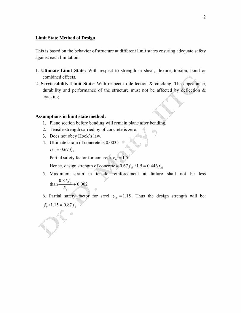
Limit State Method of Design This is based on the behavior of structure at different limit states ensuring adequate safety against each limitation. 1. Ultimate Limit State: With respect to strength in shear, flexure, torsion, bond or
combined effects. 2. Serviceability Limit State: With respect to deflection & cracking. The appearance,
durability and performance of the structure must not be affected by deflection & cracking.
Assumptions in limit state method:
1. Plane section before bending will remain plane after bending. 2. Tensile strength carried by of concrete is zero. 3. Does not obey Hook`s law. 4. Ultimate strain of concrete is 0.0035
ckc f67.0=σ
Partial safety factor for concrete 5.1=mγ
Hence, design strength of concrete ckck ff 446.05.1/67.0 ==
5. Maximum strain in tensile reinforcement at failure shall not be less
than 002.087.0
+s
y
Ef
6. Partial safety factor for steel 15.1=mγ . Thus the design strength will be:
yy ff 87.015.1/ =

3

4
Balanced section: Compression strain in concrete = 0.0035 Tensile strain in steel = yield strain Under Reinforced Section: Compression strain in concrete < 0.0035 Tensile strain in steel = yield strain Over Reinforced section: Tensile strain in steel < yield strain Compression strain in concrete = 0.0035
Under Reinforced Section is Preferable
5
Lecture Note – 2
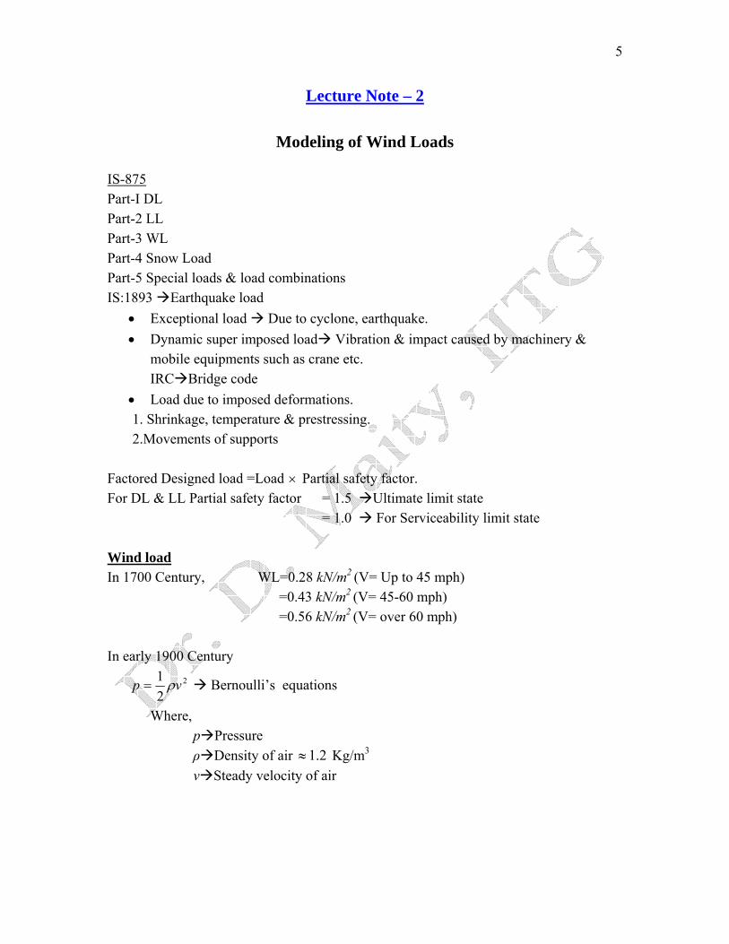
Modeling of Wind Loads IS-875Part-I DL Part-2 LL Part-3 WL Part-4 Snow Load Part-5 Special loads & load combinations IS:1893 Earthquake load
• Exceptional load Due to cyclone, earthquake. • Dynamic super imposed load Vibration & impact caused by machinery &
mobile equipments such as crane etc. IRC Bridge code
• Load due to imposed deformations. 1. Shrinkage, temperature & prestressing. 2.Movements of supports
Factored Designed load =Load × Partial safety factor. For DL & LL Partial safety factor = 1.5 Ultimate limit state = 1.0 For Serviceability limit state Wind load In 1700 Century, WL=0.28 kN/m2 (V= Up to 45 mph) =0.43 kN/m2 (V= 45-60 mph) =0.56 kN/m2 (V= over 60 mph) In early 1900 Century
2
21 vp ρ= Bernoulli’s equations
Where, p Pressure
ρ Density of air 2.1≈ Kg/m3
v Steady velocity of air

6
Indian Code for wind loads There are 6 zones in India having basic wind speed of 33, 39, 44, 47, 50 & 55 m/s. 55 m/s. Only Silchar & Ladakh Hilly Area Design Wind speed
321 kkkVV bz =
Where, Design wind speed in m/s at height Z zV
bV Basic wind speed.
1K Probability factor or risk factor.
2K Factor for the combined effects of terrain height & size of the component on structure.
3K Factor for local topography (i.e. hills, valleys etc.)
1K Table -1 of IS-875 part-3 K2 Depends on
a) Type of terrain. b) Height of building c) Size of structure K2 is given in Table-2 Type of terrain Category 1: Exposed open terrain with no obstruction. Category 2: Open terrain with scattered obstruction of height between 1.5m to 10m. Category 3: Terrain with numerous low rise (10m) obstructions.(Outskirts of City) Category 4: Terrain with numerous high rise obstructions.(City centre) Size of Structure – Depends on the largest dimension of structure for different Class Class A: Structure & components such as cladding , glazing, roofing etc. having maximum dimensions less than 20m. Class B: Structure & components as above with maximum dimension 20m to 50 m. Class C: Structure & components as above with maximum dimension greater than 50 m. In USA , UK following formula is used to calculate the velocity

7
a
ogh h
hVV ⎟⎟⎠
⎞⎜⎜⎝
⎛=
Where, Velocity at height h. hV
Velocity at ground. gV
Height of the ground. oh
Height of the structure . h From 1/10 to 1/12 depending upon site conditions. a Value of the topography factor 3K
Topographical features such as hills, valleys, cliffs, significantly alter the wind speed.
K3 =1.0 if 03<θ =1.0 to 1.36 if 03>θ
From IS:875

8
eL =Effective horizontal length
eL =L when 00 173 to=θ
=3.0
Z when 017>θ
Where,
L= Horizontal length of the upwind slope. Z= Effective height of the feature. θ=Upwind slope in the wind direction.
3 1 sK C= +
LZC .2.1= (for to 1703=θ 0)
=0.36 (for ) 017>θ
S = A function of distance ratioeL
X and the height ratio eL
H of the point being considered.

9
Wind Effects on Structure Static & Dynamic effects of wind on Structure
Type of Structure Effect of Wind 1.Very stiff structure like low rise building. 2.Flexible structure like chimneys, tall buildings with natural frequency greater than that of wind. 3.Flexible structure with natural frequency equal to that of the fluctuating part of the wind.
A. No deflection. B. Pressure quasi-static. A. Structure deflects. B. Pressure dynamic. C. Resonance effect nil. Both along & across wind effects are possible. A. Structure undergoes large deflection. B. Effects of deflection can be larger than wind effect. C. Resonance with damping. Both along & across wind effects are possible.
Clause 7.1 of IS 875 Part-3 7. DYNAMIC EFFECTS 7.1 General - Flexible slender structures and structural elements shall be investigated to ascertain the importance of wind induced oscillations or excitations along and across the direction of wind.

10
In general, the following guidelines may be ‘used for examining the problems of wind induced oscillations:
a) Buildings and closed structures with a height to minimum lateral dimension ratio of more than about 5.0. and
b) Buildings and closed structures whose natural frequency in the first mode -is less than 1.0 Hz.
Any building or structure which does not satisfy either of the above two criteria shall be examined for dynamic effects of wind. NOTE 1 - The fundamental time period (T) may either be established by experimental observations on similar buildings or calculated by any rational method of analysis. In the absence of such data, T may be determined as follows for multi-storeyed buildings: a) For moment .resisting frames without bracing or shear walls for resisting the lateral loads
T-=0.1 n Where, n = number of storeys including basement storeys; and b) For all others
0.09HTd
=
Where, H - total height of the main structure of the building in metres, d = maximum base dimension of building in metres in a direction parallel to the applied wind force.
Design wind pressure
26.0 zz Vp =
zV
zp Design wind pressure in N/m2at height Z.
Design wind velocity in m/s at height Z. Wind pressure and force on structure The wind load on a structure shall be calculated for : a) The building as a whole Using pressure coefficient. b) Individual structural elements as roofs & walls. Using force coefficient.

11
Effect of Wind on Structure The internal pressure depends on the locations & size of the openings. 1. Pressure coefficients for components Pressure coefficients are given in Table 4 to 22. Force = ( )pACC pipe − Clause 6.2.1 (pp-13)
2. Force coefficient for structure as a whole Force = ef AC ρ
C Force coefficient –Table-23 f
eA p Pressure Effective area of the building.

12
Lecture Note – 3
Wind Load on Buildings
Example: A reinforced framed building is 45 ×15 m in plan and 60 m in height consisting of storeys 4m in height. It is braced in the longitudinal direction by rigid frame action and by a reinforced concrete infill wall in the transverse direction. Determine the design wind force on the framed building. Assume that the building is situated in terrain category 3 with basic wind speed of 50 m/s in a fully developed velocity profile. Solution: Step1: Data Plan of building = 45×15 m; height =60 m Basic wind speed =50 m/s Step2: Find the design wind speed zV
321 kkkVV bz =
Risk factor ; Topography factor 0.11 =k 0.13 =k
26.0 zz Vp =
Factor depends upon the following: 2ki) Terrain category 3 ii) Structural size factor – greater horizontal or vertical dimensions is larger than 50 m . 15 m gust size is appropriate. Hence class C. Read off for terrain category 3 and class C for varying heights, the value of . 2k 2kFor convenience, the heights is divided into three divisions & the greater value for each division is used, i.e. (0-20 m,20-40 m, and 40-60 m) Step 3: Determine dynamic pressure for different heights Pressure
[Ref. clause 5.4 of IS:875] Table 1(From Table 2 of IS:875)
Interval (max) (m/s) p(N/m2k zV 2) 0-20 0.91 45.5 1242 20-40 1.00 50.0 1500 40-60 1.04 52.0 1622

13
Step4: Calculate the force coefficients fC
Let, Wind be normal to 45 m base = wind at 00. Wind be normal to 15 m base = wind at 900
a = Depth of plan dimension=15 m b = Dimensions on which wind at 00 acts =45m h =Height=60 m
Table 2 (from fig. 4 of IS:875) Dimension wind at 00 wind at 900 a/b 15/45=0.33 45/15=3.0 h/b 60/45=1.33 60/15=4.0 Cf 1.3 1.1
Step5: Determine forces of wind at 00. Wind force = (Area) fpC
Area = 45 (Floor height of 4m)
( )45
4453. ×p p2.1 =5 for each meter of length. UDL on floor slab =
Tabulating for the intervals adopted. Table 3
Interval p(N/m2) Force(KN/m) 0-20 1242 5.2p=6.46 20-40 1500 5.2p=7.80 40-60 1622 5.2p=8.43
Step 6: Determine wind forces in 900 direction.
454451.1 ××× pAs above = = for each meter of length. p4.4
Step7: Nature of action of Wind forces:
These uniformly-distributed forces from the edge of the slab are transferred to the frames and shear walls. The floor slab acts as rigid diaphragms between the walls and the frame.

14
Lecture Note – 4
Material Characteristics
Cement The most common types of Portland Cements are as follows Portland Cement _______________________________|___________________________________ | | | | | | | | OPC RHPC PSC PPC HPC LHPC SRPC PWC 1. Ordinary Portland Cement (OPC): 3 different grade denoting compressive strength C33, C43, C53 corresponding to 28 days characteristic strength & conforming to IS269, IS8112 & IS 12269 respectively. 2. Rapid Hardening Portland Cement (RHPC): Conforming to IS8041. Similar to OPC except more tricalcium silicate (C3 S) & less dicalcium silicate (C2S). 3. Portland Slag Cement (PSC): Conforming to IS455. Suitable to use in environments exposed to sulphates. 4. Portland Pozzolana Cement (PPC): Conforming to IS1489.Flyash based or calcined clay based. It is comparatively cheaper. 5. Hydrophobic Portland Cement (HPC): Conforming to IS8043. It has water resistant property. 6. Low Heat Portland Cement (LHPC): Conforming to IS12600 7. Sulphur Resistant Portland Cement (SRPC): Conforming to IS12330 8. Portland White Cement (PWC): Conforming to IS8042 Other Cements 1. High Alumina Cement (HAS): It is recommended in marine environments. 2. Supersulphate Cement (SC):
15
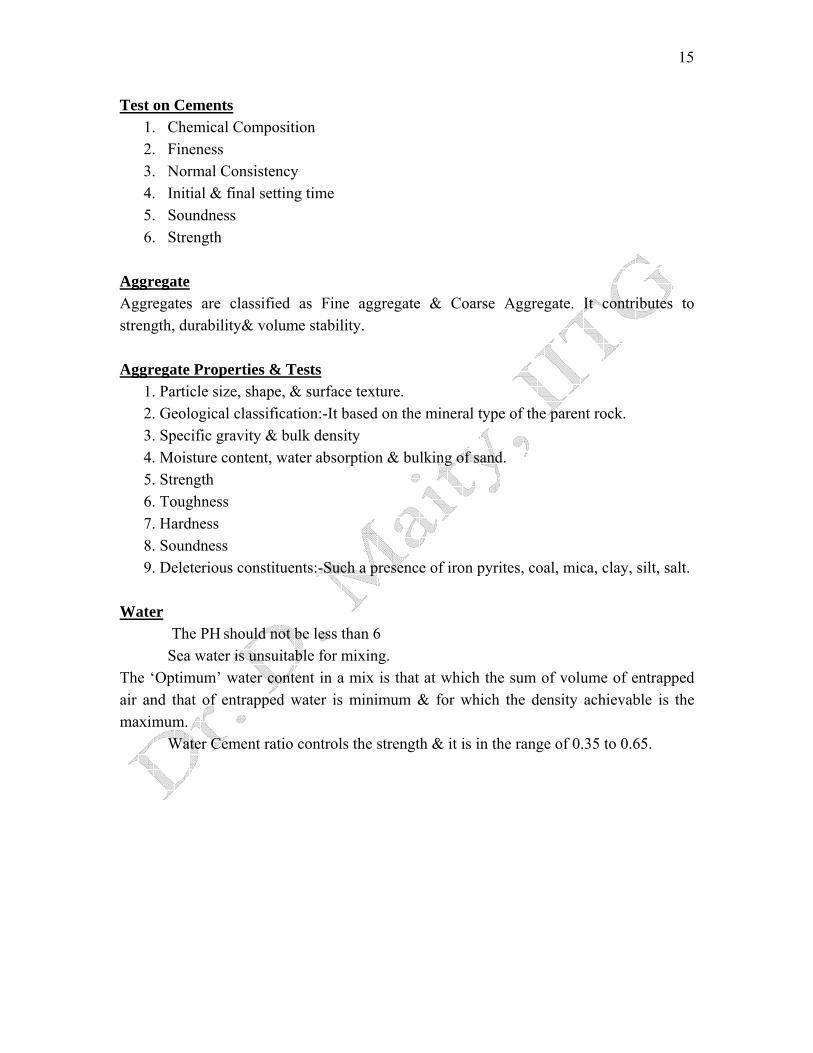
Test on Cements 1. Chemical Composition 2. Fineness 3. Normal Consistency 4. Initial & final setting time 5. Soundness 6. Strength
Aggregate Aggregates are classified as Fine aggregate & Coarse Aggregate. It contributes to strength, durability& volume stability. Aggregate Properties & Tests
1. Particle size, shape, & surface texture. 2. Geological classification:-It based on the mineral type of the parent rock. 3. Specific gravity & bulk density 4. Moisture content, water absorption & bulking of sand. 5. Strength 6. Toughness 7. Hardness 8. Soundness 9. Deleterious constituents:-Such a presence of iron pyrites, coal, mica, clay, silt, salt.
Water
The PH should not be less than 6 Sea water is unsuitable for mixing.
The ‘Optimum’ water content in a mix is that at which the sum of volume of entrapped air and that of entrapped water is minimum & for which the density achievable is the maximum.
Water Cement ratio controls the strength & it is in the range of 0.35 to 0.65.

16
Fig:-1
Admixtures It is an additive to modify the properties of concrete. Type of Chemical Admixtures
1. Accelerator: It accelerates the hardening or the development of early strength. 2. Retarders: It retards the setting of concrete & thereby to reduce the generation of
heat. 3. Water Reducers or Plasticizers: It improves the plasticity in the fresh concrete.
These are used to achieve higher strength by reducing the w/c ratio for improving workability.
4. Super plasticizer or High range water reducer: Superior to conventional water reducer.
5. Air-entraining agent: Organic compounds which introduce discrete & microscopic air bubble cavities.
6. Bonding admixture: Polymer emulsions to improve the adherence of fresh concrete to hardened concrete. They are ideally suited for repair work.
17
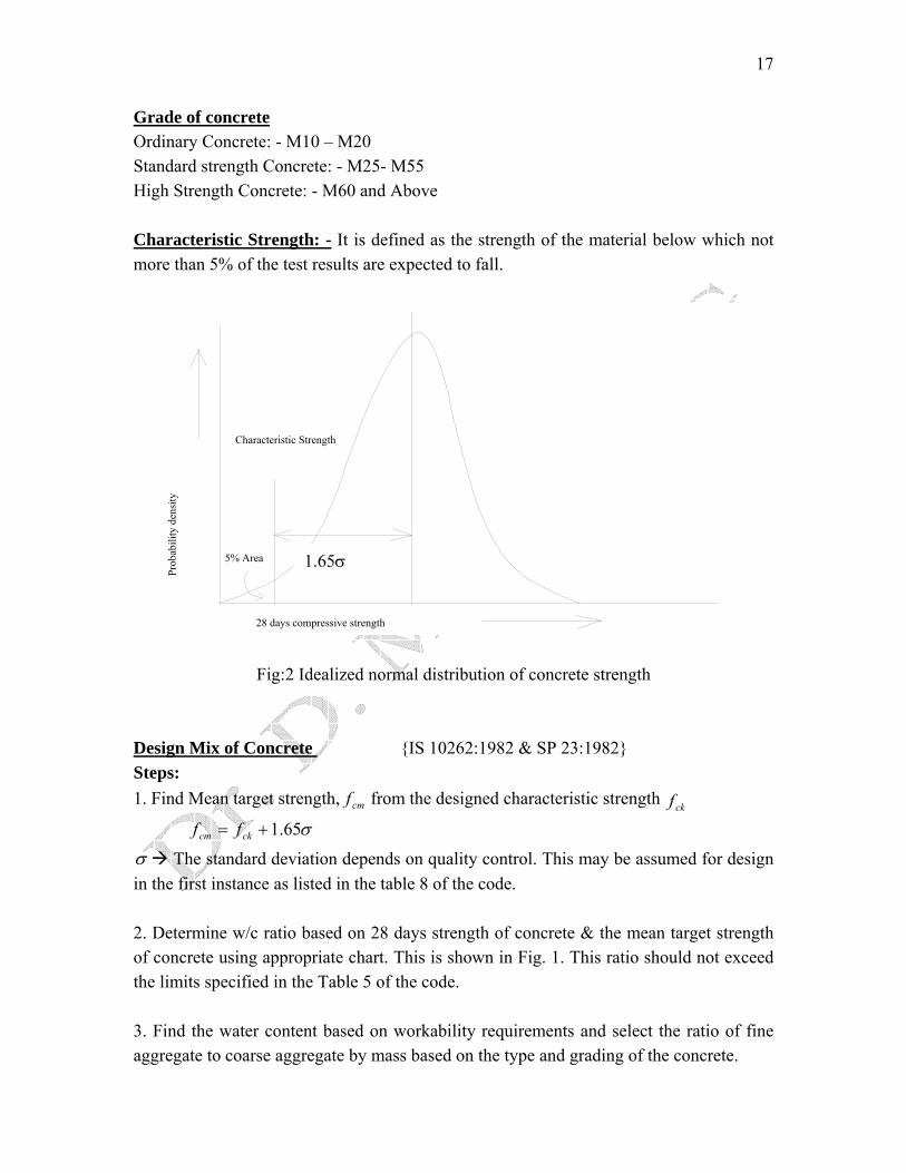
Grade of concrete Ordinary Concrete: - M10 – M20 Standard strength Concrete: - M25- M55 High Strength Concrete: - M60 and Above Characteristic Strength: - It is defined as the strength of the material below which not more than 5% of the test results are expected to fall.
28 days compressive strength
Prob
abili
ty d
ensi
ty
5% Area
Characteristic Strength
1.65σ
Fig:2 Idealized normal distribution of concrete strength Design Mix of Concrete {IS 10262:1982 & SP 23:1982} Steps: 1. Find Mean target strength, cmf from the designed characteristic strength ckf
σ65.1+= ckcm ff
σ The standard deviation depends on quality control. This may be assumed for design in the first instance as listed in the table 8 of the code.
2. Determine w/c ratio based on 28 days strength of concrete & the mean target strength of concrete using appropriate chart. This is shown in Fig. 1. This ratio should not exceed the limits specified in the Table 5 of the code. 3. Find the water content based on workability requirements and select the ratio of fine aggregate to coarse aggregate by mass based on the type and grading of the concrete.

18
4. Calculate Cement content in kg/m3. Ensure that the cement content is not less than that specified in the code in the Table 4 & 5 for durability consideration. 5. Calculate masses of fine aggregates faM and coarse aggregate based on the
absolute volume principle. caM
0.1=++++ vwca
ca
fa
fa
c
c vvMMMρρρ
Where cafac ρρρ ,, mass densities of cement , fine & coarse aggregate respectively
vw vv & Volume of water content & volume of voids per cubic meter concrete.
6. Calculate the weight of ingredients for batch, based on the capacity of the concrete mixer.
Properties of Concrete Test of concrete strength in compression Cube→150mm × 150mm × 150mm Cylinder →150mm φ × 300mm height Cylinder strength is lower than cube strength.
Fig. 3 Influence of height/diameter ratio on the apparent strength of a cylinder

19
Rel
ativ
e st
reng
th
0.8
0.9
Diameter in mm
150 300
1.1
1.0
450 600 900750
height/diameter=2.0Standard
Fig: 4 Influence of diameter on the apparent strength of a cylinder
Com
pres
sive
stre
ss(M
Pa)
Strain0.001 0.002 0.003 0.004
10
20
30
40
50
60
Fig: 5 Typical stress-strain curves of concrete in compression
Higher concrete grade Initial portion is steeper Peak is sharpen Failure strain is less.

20
For lower strength concrete Higher failure strain Curve is relatively flat top Maximum stress reached approximately at a strain of 0.002 Strain at failure is from 0.003 to 0.005 Stress-strain relation for the compression zone of a RC flexure number is nearly identical to that obtained for uniaxial compression.
Specified stress level
stre
ss
Strain
Unloading path
T
Loading path
S
IT
IT Initial tangent T tangent S Secant
Dynamic modulus of elasticity: It can be measured from initial tangent modulus. This is applicable for cyclic loading such as wind, earthquake, where long term effects are negligible. Static modulus of elasticity: This is used for long term duration of load like DL, LL
ckc fMPaE 5000)( = (Clause 6.2.3.1 of IS 456:2000)
Earlier, ckc fE 5700= (Over estimation of Ec)
( )3 /0.0427c c cE fρ= ACI code suggest

21
Where, cρ is the mass density of concrete in kg/m3 =2400 kg/m3 generally '
cf =Cylinder strength
Thus, ckc fE 4500= , Where ' 0.8c ckf f=
Influence of duration of loading
Fig: 6 Influence of duration of loading on stress strain curve of concrete
Concrete Under Tension
• Stress-strain is linear. • Maximum strain under uniaxial tension is 0.0 02 to 0.0003
Modulus of Rupture ( )crf
ZMfcr =
Assuming a linear stress distribution along the cross section. IS code: Clause no 6.2.2 ckcr ff 7.0=→ in MPa
ACI code: /623.0 ccr ff =
0

22
Splitting Tensile strength
dLPfct π
2=Splitting tensile strength, .
Generally, crct ff32
≈

23
Lecture Note – 5
Properties of Concrete Creep of concrete Time dependent component of total strain is termed creep.
• Exact mechanism of creep in concrete is still not clear. • It is generally attributed to internal movement of absorbed water, viscous flow or
sliding between the gel particles, moisture loss & growth in micro cracking. Effect of creep
• Increased deflection of beam and slabs. • Increased deflection of slender columns (possibly leading to buckling) • Gradual transfer of load from concrete to steel in compression.. • Loss of prestress in prestressd concrete.
Factor influencing Creep 1. Material properties 2. Composition 3. Curing 4. Loading condition 5. Environmental condition

24
Creep increases if 1. Cement content is high 2. Water Cement ratio is high 3. Aggregate content is low 4. Air entrainment is high 5. Relative humidity is low 6. Temperature is high (causing moisture loss) 7. Size/thickness of member is small. 8. Loading occurs at early stage 9. Loading is sustained over a long period Creep coefficient for design IS code: Clause 6.2.5.1 Ultimate creep coefficient ( )θ 2.2 for ages of loading =7 days 1.6 for ages of loading =28 days 1.1 for ages of loading = 1 Year
θ+=
1c
ceE
E (Clause 4.1) Effective modulus of Elasticity,
Durability If concrete is to serve the purpose for which it is designed during its intended lifetime, it has to be durable. Loss of durability results a reduced life of structure. Loss of durability happens due to chemical attack. Durability of concrete can be increased by 1. Reducing permeability by
• Providing high grade of concrete • Using adequate cement content • Using well graded , dense aggregate • Using low water cement ratio • Using appropriate admixture • Achieving maximum compaction • Achieving effective curing • Using appropriate surface coatings & impermeable membranes . • Avoiding sharp corners &locations where compaction is difficult. • Taking care while designing to minimize possible cracks

25
2. Providing appropriate type of cement having the desired chemical resistance to sulphates & chlorides. 3. Avoiding the use of alkali-reactive aggregates 4. Providing direct protection to embedded steel against corrosion by
• Using appropriate corrosion resistant coated steel. • Providing adequate clear cover • Using sophisticated techniques such as cathodic protection
5. Controlling the chloride & sulphate contents in the concrete mix constituents. 6. Providing air-entering admixture when resistance against freezing & thawing is required. 7. Providing adequate thickness is required. 8. Providing adequate reinforcement designed to contain crack widths within acceptable limits. 9. Providing adequate drainage on concrete surfaces to avoid water retention. Environmental exposure & code Requirements (Clause 8.2.2) The code identifies 5 category of environmental Exposure. Viz i) Mild ii) Moderate iii) Severe iv) Very severe v) Extreme Minimum requirements
• Minimum grade of Concrete (M20 to M40) • Minimum clear cover to reinforcement (20mm to 75mm) • Minimum cement content ratio (300-360kg/m3 for 20 mm size aggregate) • Maximum water cement ratio (0.55 to 0.40) • Acceptable limits of surface s width of cracks (0.1 mm to 0.3mm)

26
Reinforcing Steel Assumption: Stress –strain behavior of steel in compression is similar to that in tension.
Stress-strain behavior of different steel
Bauschinger effect & Hysteresis