lect11 organization
TRANSCRIPT

Computer Organization
Instructors :
Dr. Abdul Raouf Khan
Mr.Marwan El-Haj
Computer Organization
Lec.11:Complete Computer Description
Last Lecture

Basic Computer Consists of:

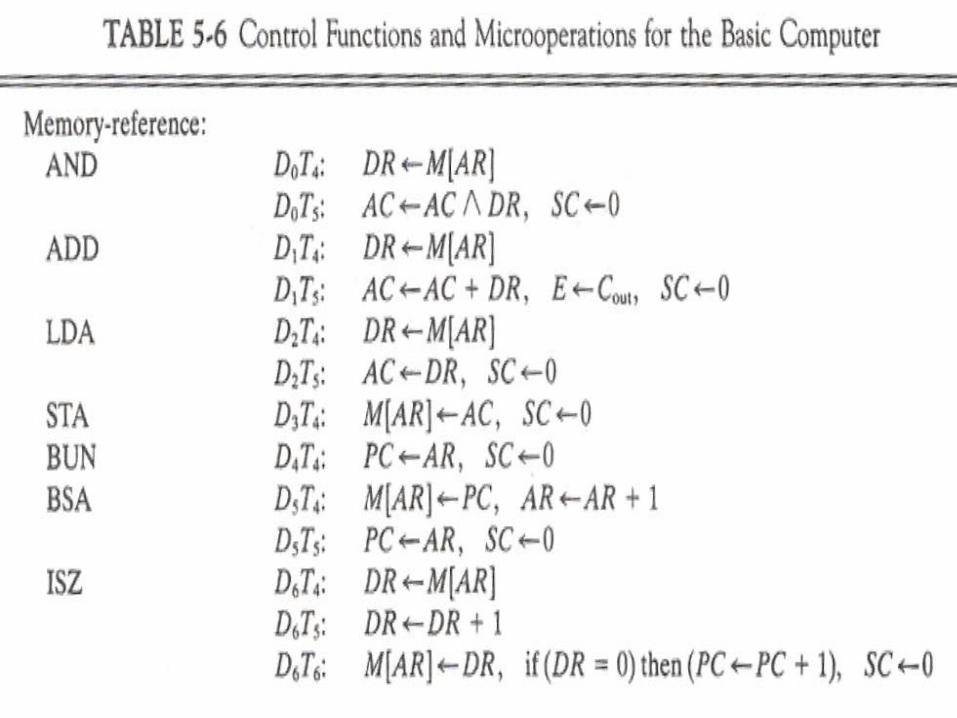
Complete Computer Description
A Register Transfer Language useful for describing internal organization of a digital system, and logic circuits needed for its design
– Table 5-6 Summarizes: Control Functions for Entire Computer
Micro-operations for Entire Computer
– Register Transfer Statements Describes Internal organization.
Information to design logic circuits of computer.
– Control Functions and conditional control statements Formulates Boolean functions for control units gates
– List of micro-operations Specifies types of control inputs needed for registers and memory


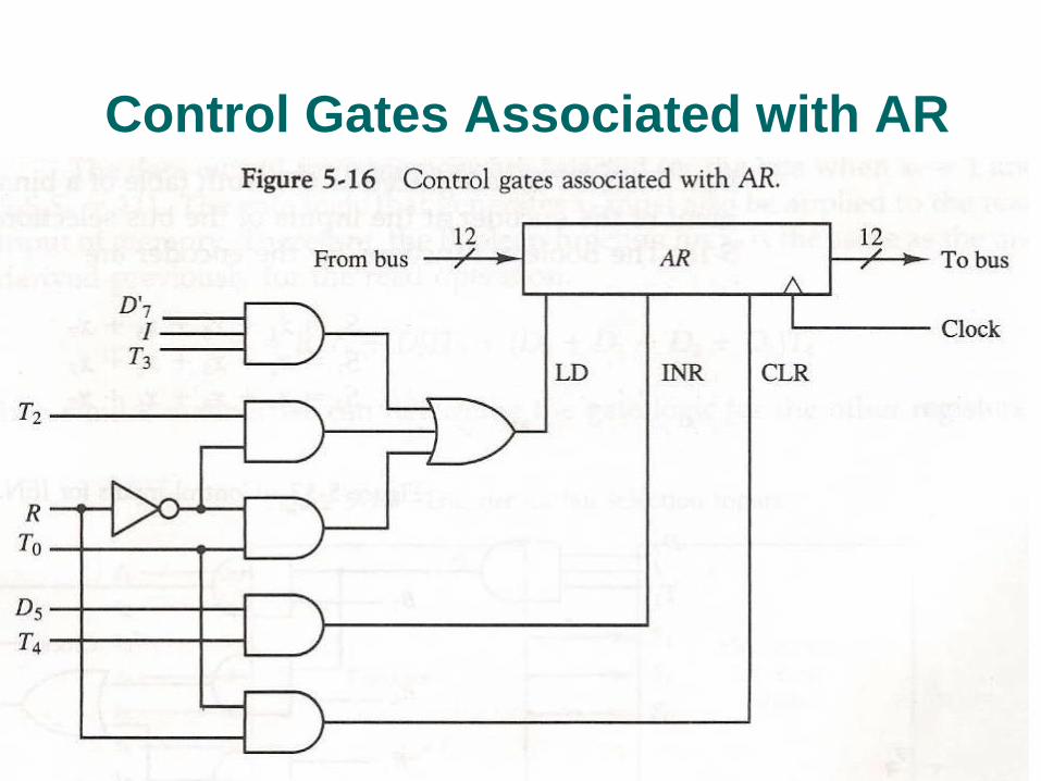
Control Gates Associated with AR

Control of Single FLIP FLOP
The control gates for the seven flip flops can
be determined in a similar way. For example
IEN may change as result of two instructions
ION & IOF
pB7: IEN1
pB6: IEN0 where p=D7IT3 also
RT2: IEN0 at the end of Interrupt cycle
Figure below shows the control logic

Control of Single FLIP FLOP
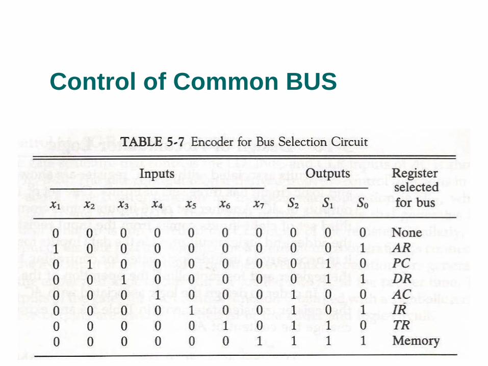
Control of Common BUS

Control of Common BUS

Design of Accumulator Logic

Control of AC register


Adder & Logic Circuit
The adder and logic circuit can be divided into
16 stages, with each stage corresponding to
one bit of AC.
The one stage of adder and logic circuit is
shown as below.


Assignments
1. A computer uses a memory unit with 256K words of 32 bit each. A binary instruction code is stored in one word of memory. The instruction has four parts: an indirect bit, an operation code, a register code part and the address part. The system has 32 registers.
a. How many bits are there in the operation code, the register code part and the address code part?
b. Draw the instruction word format
c. How many bits are there in the data & address inputs of the memory?
d. What is the maximum number of instructions we can have in this computer?

Exercise 1
The following control inputs are active in our
BUS system. For each case specify the
register transfer that will be executed during
next clock
S2 S1 S0 LD of register Memory Adder
A 1 1 1 IR Read --
B 1 1 0 PC --- --
C 1 0 0 DR Write --
D 0 0 0 AC -- Add

Exercise 2
The following register transfers are to be executed in our System.
For each transfer, specify (1). the binary value to be applied to bus
select inputs S0,S1, S2. (2) the register whose LD control must be
active (3) a memory READ or Write (if needed) (4) the operation in
the adder & logic circuit.
a. AR PC
b. IR M[AR]
c. M[AR]TR
d. ACDR, DRAC (done simultaneously)

Exercise 3
Explain why each of the following
microoperations cannot be executed during a
single clock in the system.
a. IRM[PC]
b. AC AC+TR
c. DR DR + AC (AC does not change)