lect 7 testbench k14 v02 - computer engineering at … · · 2014-02-04lecture 7: vhdl...
TRANSCRIPT

Lecture 7: VHDL Testbenches
Erno Salminen 2014
TKT-50200 Logiikkasynteesi
Testbench
Design under test

Contents Purpose of test benches
Structure of simple test bench Side note about delay modeling in VHDL
Better test benches Separate, better reusable stimulus generation Separate sink from the response File handling for stimulus and response
Example and conclusions

Introduction Verification is perhaps the most difficult aspect of any design That’s not an excuse for omitting it or leaving it to others… Multiple levels: single component, module with multiple sub-
components, and system-level
[http://blogs.mentor.com/verificationhorizons/blog/2011/04/03/part-4-the-2010-wilson-research-group-functional-verification-study/slide13-2-2/}
Multiple abstaction levels In synchronous design, we
verify the functionality at cycle-level accuracy Not detailed timing,
which will be checkedwith static timing analysis(STA) tools

Introductory questionQ: What’s the difference betweentheory and practise?
A1: In theory there’s no difference...
A2:In theory everything works. In practice nothing works.
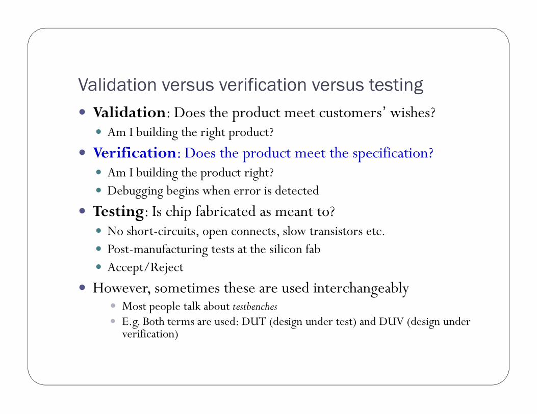
Validation versus verification versus testing Validation: Does the product meet customers’ wishes?
Am I building the right product?
Verification: Does the product meet the specification? Am I building the product right? Debugging begins when error is detected
Testing: Is chip fabricated as meant to? No short-circuits, open connects, slow transistors etc. Post-manufacturing tests at the silicon fab Accept/Reject
However, sometimes these are used interchangeably Most people talk about testbenches E.g. Both terms are used: DUT (design under test) and DUV (design under
verification)
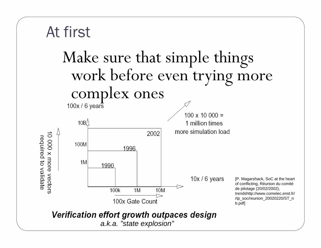
At first
[P. Magarshack, SoC at the heart of conflicting, Réunion du comité de pilotage (20/02/2002),trendshttp://www.comelec.enst.fr/rtp_soc/reunion_20020220/ST_nb.pdf]
a.k.a. ”state explosion”
Make sure that simple things work before even trying more complex ones
Verifying as part of system
separate testbench
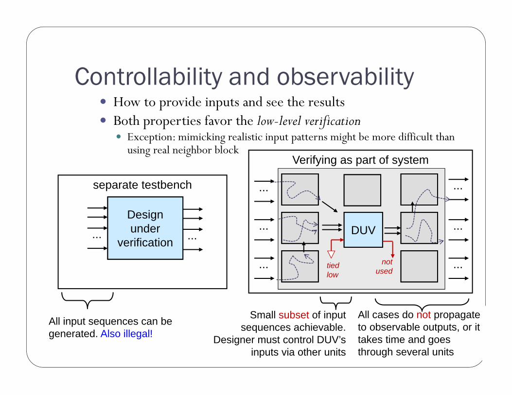
Controllability and observability
Design under
verification... ... DUV ...
...
......
...
...
All input sequences can begenerated. Also illegal!
notused
tiedlow
Small subset of input sequences achievable.
Designer must control DUV’sinputs via other units
All cases do not propagateto observable outputs, or ittakes time and goesthrough several units
How to provide inputs and see the results Both properties favor the low-level verification
Exception: mimicking realistic input patterns might be more difficult thanusing real neighbor block

What is a VHDL Test Bench (TB)? VHDL test bench (TB) is a piece of code meant to verify the
functional correctness of HDL model The main objectives of TB is to:
1. Instantiate the design under test (DUT)2. Generate stimulus waveforms for DUT3. Generate reference outputs and compare them with the outputs of
DUT4. Automatically provide a pass or fail indication
Test bench is a part of the circuits specification Sometimes it’s a good idea to design the test bench before the
DUT Functional specification ambiguities found Forces to dig out the relevant information of the environment Different designers for DUT and its tb!

Testbench benefits Unit is inspected outside its real environment Of course, TB must resemble the real environment MakingTB realistic is sometimes hard, e.g. interface to 3rd
party ASIC which does not have a simulation model
Isolating the DUT into TB has many desirable qualities Less ”moving parts”, easier to spot the problem Easy to control the inputs, also to drive illegal values Easy to see the outputs Small test system fast to simulate Safer than real environment, e.g. better to test emergency
shutdown first in laboratory than in real chemical factory

Stimulus and Response TB can generate the stimulus (input to DUT) in several ways:
a) Read vectors stored as constants in an arrayb) Read vectors stored in a separate system filec) Algorithmically “on-the-fly”d) Read from C through Foreign Language Interface (FLI, Modelsim)
The response (output from DUT) must be automatically checked. Expected response must be known exactly Response can be stored into file for further processing.
Example: Stimulus can be generated with Matlab and TB feeds it into DUT. DUT generates the response and TB stores it into file. Result are compared to Matlab simulations automatically, no manual
comparison!

Choosing test methodA. Manual
generate test with modelsimforce command
check the wave forms
B. Automated test generation and response checking
B is the only viable option
This real-life figure shows only 1/3 of signals
1/50 000 of time line
This check should be repeatedfew times a day duringdevelopment...
1 000 cycles
clk signal
11

Verification can find bugs, prove equivalence, and proveinteresting properties of a design
Verification cannot prove correctness It can show the existence of bugs, but not their non-existence We can show cases when the design works
Nevertheless, we do achieve high quality through verification
Quality needs to be designed in (and then verified), not verifiedin
Completion condition should be explicitly stated E.g. statement/coverrage/state covergage > 98%, #new
bugs/week <0.5, all time/money spent, we’re bored with it…
Philosophical note[after Keating]

Other philosophical note TB tests the DUT against the interpretation of specification
(which is interpreted from requirements) Specification may have flaws Ambiguity Not meeting the customer’s desires
Testbench may have mistakes False interpretation Testbench codes may have bugs
Good to have different persons writing the actual code and testbench Less likely that both make the same miss-interpretation

Test Bench Structures TB should be reusable without difficult modificationsModular design
The structure of the TB should be simple enough so that other people understand its behaviour
It has to be easy to run Not much dependencies on files or scripts
Good test bench propagates all the generics and constants into DUT
Question: How to verify that the function of the test bench is correct? A: “Sanopa muuta kato”

Simple Test Bench Only the DUT is instantiated into test bench. Stimulus is generated inside the test bench Not automatically – handwritten code trying to spot corner cases Poor reusability.
Suitable only for very simple designs, if at all However, such “tb” can be used as an usage example to familiarize
new user with DUT “See, driving input like this makes the DUT do something useful...”.
Better than none, but not
reliable
stimulus
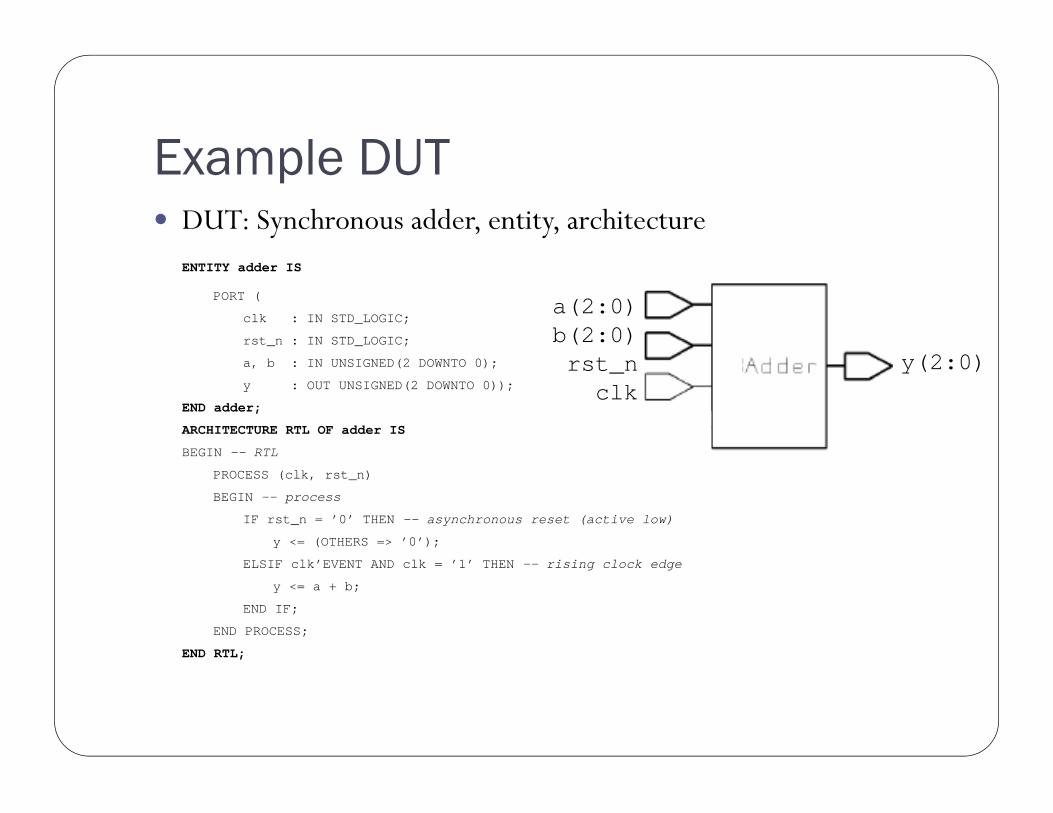
Example DUT DUT: Synchronous adder, entity, architecture
ENTITY adder IS
PORT (
clk : IN STD_LOGIC;
rst_n : IN STD_LOGIC;
a, b : IN UNSIGNED(2 DOWNTO 0);
y : OUT UNSIGNED(2 DOWNTO 0));
END adder;
ARCHITECTURE RTL OF adder IS
BEGIN -- RTL
PROCESS (clk, rst_n)
BEGIN -- process
IF rst_n = ’0’ THEN -- asynchronous reset (active low)
y <= (OTHERS => ’0’);
ELSIF clk’EVENT AND clk = ’1’ THEN -- rising clock edge
y <= a + b;
END IF;
END PROCESS;
END RTL;
a(2:0)b(2:0)rst_nclk
y(2:0)

Simple TB (3): entity without ports Test bench Simplest possible entity declaration:
ENTITY simple_tb ISEND simple_tb;
Architecture:ARCHITECTURE stimulus OF simple_tb IS
DUT:COMPONENT adderPORT (
clk : IN STD_LOGIC;
rst_n : IN STD_LOGIC;
a, b : IN UNSIGNED(2 DOWNTO 0);
y : OUT UNSIGNED(2 DOWNTO 0)
);
END COMPONENT;

Simple TB (4): instantiate DUT and generate clock Clock period and connection signals:
CONSTANT period : TIME := 50 ns;
SIGNAL clk : STD_LOGIC := ’0’; -- init values only in tbSIGNAL rst_n : STD_LOGIC;SIGNAL a, b, y : unsigned(2 downto 0);
Begin of the architecture and component instantiation:begin
DUT : adder
PORT MAP (clk => clk,rst_n => rst_n,a => a,b => b,y => y);
Clock generation:generate_clock : PROCESS (clk)
BEGIN -- processclk <= NOT clk AFTER period/2; -- this necessitates init value
END PROCESS;

Simple TB (5): stimulus and config Stimuli generation and the end of the architecture:
rst_n <= ’0’,’1’ AFTER 10 ns;
a <= "000","001" AFTER 225 ns,"010" AFTER 375 ns;
b <= "000","011" AFTER 225 ns,“010" AFTER 375 ns;
end stimulus; -- ARCHITECTURE
Configuration:CONFIGURATION cfg_simple_tb OF simple_tb ISFOR stimulusFOR DUT : adder
USE ENTITY work.adder(RTL);END FOR;
END FOR;END cfg_simple_tb;
Not very comprehensive

Simple TB (6): sim results Simulation:
You notice that is does something but validity is hard to ensure.
How to check correcteness?
Take your eye into hand and watch.Not too convenient...

VHDL delay modeling Signal assignments can have delay (as in prev example)
1. Inertial delays Used for modeling propagation delay, or RC delay
1.after2.reject-inertial Useful in modeling gate delays Glitches filtered
2.transport delay transmission lines testbench stimuli generation glitches remain
R
C
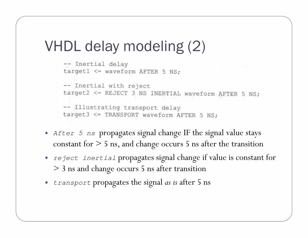
VHDL delay modeling (2)
After 5 ns propagates signal change IF the signal value stays constant for > 5 ns, and change occurs 5 ns after the transition
reject inertial propagates signal change if value is constant for > 3 ns and change occurs 5 ns after transition
transport propagates the signal as is after 5 ns

VHDL delay modeling (3)
Be careful! Behavior will be strange if the edges of the clk and signal generated this way are aligned.

More elegant test benches

Test Bench with a Separate Source Source and DUT instantiated into TB
For designs with complex input and simple output
Source can be e.g. another entity or a process

TB w/ separate src (2): structure Input stimuli for “adder” is generated in a separate entity
“counter”.

TB w/ separate src (3): create counter Stimulus source is a clock-triggered up counter
Entity of the source:
ENTITY counter ISPORT (
clk : IN STD_LOGIC;
rst_n : IN STD_LOGIC;
Y : OUT STD_LOGIC_VECTOR(2 DOWNTO 0)
);
END counter;

TB w/ separate src (4): create counter Architecture of the source component:
ARCHITECTURE RTL OF counter IS
SIGNAL Y_r : unsigned(2 downto 0)
BEGIN -- RTL
PROCESS (clk, rst_n)
BEGIN -- process
IF rst_n = ’0’ THEN -- asynchronous reset (active low)
Y_r <= (OTHERS => ’0’);
ELSIF clk’EVENT AND clk = ’1’ THEN -- rising clock edge
Y_r <= Y_r+1;
END IF;
END PROCESS;
Y <= std_logic_vector(Y_r);
END RTL;
Note: overflow not checked

TB w/ separate src (5): decalrecomponents Test bench: Architecture
ARCHITECTURE separate_source OF source_tb IS
Declare the components DUT and sourceCOMPONENT adderPORT (
clk : IN STD_LOGIC;rst_n : IN STD_LOGIC;a, b : IN UNSIGNED(2 DOWNTO 0);y : OUT UNSIGNED(2 DOWNTO 0)
);END COMPONENT;COMPONENT counterPORT (
clk : IN STD_LOGIC;rst_n : IN STD_LOGIC;y : OUT UNSIGNED(2 DOWNTO 0)
);END COMPONENT;
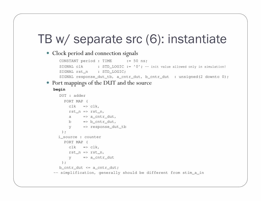
TB w/ separate src (6): instantiate Clock period and connection signals
CONSTANT period : TIME := 50 ns;SIGNAL clk : STD_LOGIC := ’0’; -- init value allowed only in simulation!
SIGNAL rst_n : STD_LOGIC;SIGNAL response_dut_tb, a_cntr_dut, b_cntr_dut : unsigned(2 downto 0);
Port mappings of the DUT and the sourcebegin
DUT : adderPORT MAP (
clk => clk,rst_n => rst_n,a => a_cntr_dut,b => b_cntr_dut,y => response_dut_tb
);i_source : counter
PORT MAP (clk => clk,rst_n => rst_n,y => a_cntr_dut
);b_cntr_dut <= a_cntr_dut;
-- simplification, generally should be different from stim_a_in

TB w/ separate src(7): clock and reset Clock and reset can be generated also without processes
clk <= NOT clk AFTER period/2; -- this style needs init value
rst_n <= ’0’, ’1’ AFTER 10 ns;
END separate_source

TB w/ separate src (8): sim results Simulation:
Overflow in adder, three bits unsigned value range 0..7
Better than previous tb.Easy to scale the stimulus length for wider adders.Quite straightforward to test all valuesby instantiating two counters.
The checking is still inconvenient.
_dut_tb
/a_cntr_dut

Response handling

Test Bench with a Separate Source and Sink Both the stimulus source and the sink are separate instances.
Complex source and sink without response-source interaction.
Sink uses assertions of some sort
stimulus response

Smart Test Bench Circuit’s response affects further stimulus. In other words, TB is reactive E.g. DUT requests source to stall, if DUT cannot accept new data at
the moment E.g. Source writes to FIFO (=DUT) until it is full, then it does
something else… Non-reactive TB with fixed delays will break immediately, if DUT’s
timing changes
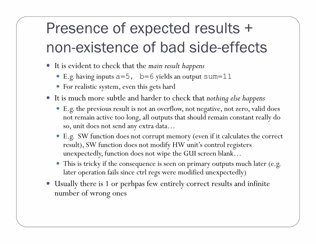
Presence of expected results + non-existence of bad side-effects It is evident to check that the main result happens
E.g. having inputs a=5, b=6 yields an output sum=11 For realistic system, even this gets hard
It is much more subtle and harder to check that nothing else happens E.g. the previous result is not an overflow, not negative, not zero, valid does
not remain active too long, all outputs that should remain constant really doso, unit does not send any extra data…
E.g. SW function does not corrupt memory (even if it calculates the correctresult), SW function does not modify HW unit’s control registersunexpectedly, function does not wipe the GUI screen blank…
This is tricky if the consequence is seen on primary outputs much later (e.g. later operation fails since ctrl regs were modified unexpectedly)
Usually there is 1 or perhpas few entirely correct results and infinitenumber of wrong ones

Check absence of side-effects! (2) TB correctly checked the the upper outputs of the ALU (those
affected with given stimulus) Implicit, false assumption was not verified! Glitch in lower signals goes undetected in TB but causes problems
in real SoC E.g. divide-by-zero rises during add operation
Goes undetected! Aargh!
ALU foo
bar
SoC fails
Component Bar is innocent butbecomes the suspect at firstwhen SoC fails!
TB waves:
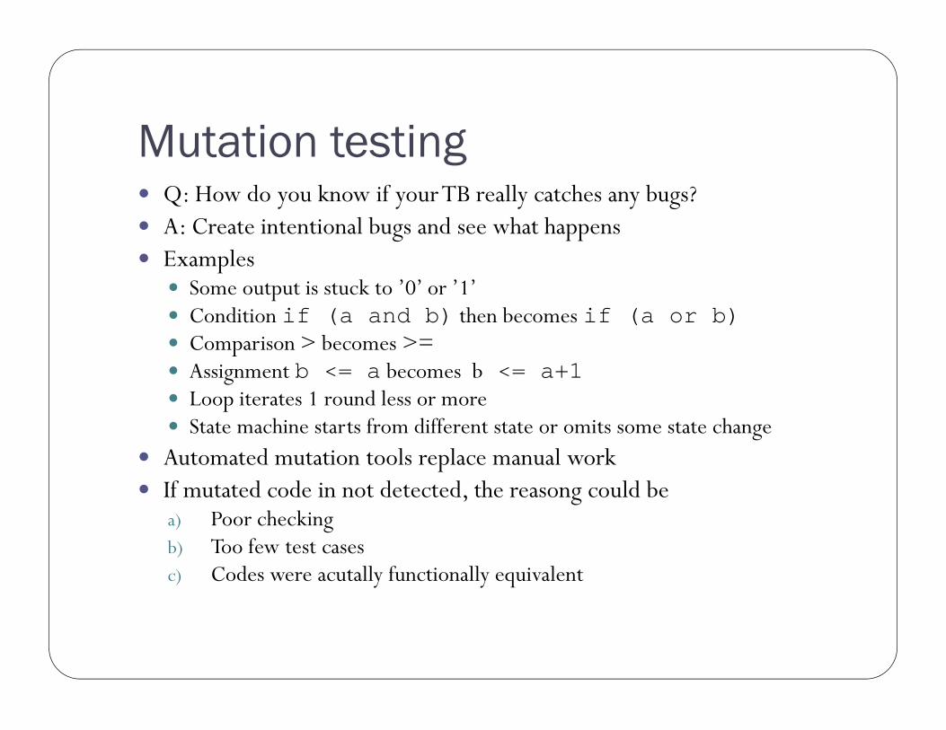
Mutation testing Q: How do you know if yourTB really catches any bugs? A: Create intentional bugs and see what happens Examples
Some output is stuck to ’0’ or ’1’ Condition if (a and b) then becomes if (a or b) Comparison > becomes >= Assignment b <= a becomes b <= a+1 Loop iterates 1 round less or more State machine starts from different state or omits some state change
Automated mutation tools replace manual work If mutated code in not detected, the reasong could be
a) Poor checkingb) Too few test casesc) Codes were acutally functionally equivalent
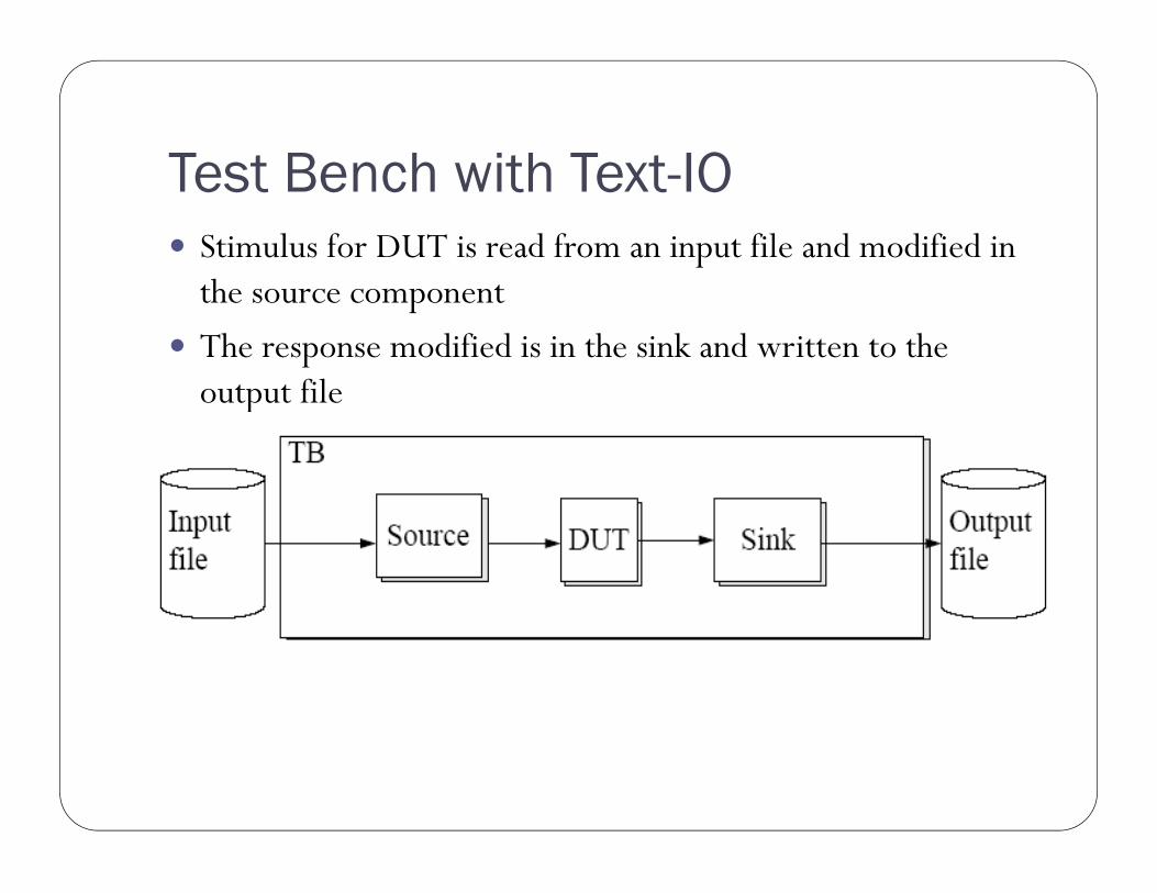
Test Bench with Text-IO Stimulus for DUT is read from an input file and modified in
the source component
The response modified is in the sink and written to the output file

TB w/ Text-IO (2): structure Test case:

TB w/ Text-IO (3): libraries Test bench:
Libraries, remember to declare the textio-library!
library IEEE;use IEEE.std_logic_1164.all;use IEEE.std_logic_arith.all; -- old skooluse std.textio.all;use IEEE.std_logic_textio.all;

TB w/ Text-IO (4): declarations Architecture
ARCHITECTURE text_io OF source_tb ISCOMPONENT adder
PORT (
clk : IN STD_LOGIC;
rst_n : IN STD_LOGIC;
a, b : IN UNSIGNED(2 DOWNTO 0);
y : OUT UNSIGNED(2 DOWNTO 0)
);
END COMPONENT;
CONSTANT period : TIME := 50 ns; -- even value
SIGNAL clk : STD_LOGIC := ’0’;
SIGNAL rst_n : STD_LOGIC;
SIGNAL a, b, y : unsigned(2 downto 0);

TB w/ Text-IO (5): clock, reset, instantiation In achitecture bodybeginDUT : adder
PORT MAP (clk => clk,rst_n => rst_n,a => a,b => b,y => y);
clk <= NOT clk AFTER period/2;rst_n <= ’0’,
’1’ AFTER 75 ns;

TB w/ Text-IO (6): process for file handling Create process and declare the input and output files (VHDL‘87)
process (clk, rst_n)FILE file_in : TEXT IS IN "datain.txt";FILE file_out : TEXT IS OUT "dataout.txt";
File paths are relative to simulation directory (the one with modelsim.ini)
Variables for one line of the input and output filesVARIABLE line_in : LINE;VARIABLE line_out : LINE;
Value of variable is updated immediately. Hence, the new value is visible on the same execution of the process (already on the next line)
Variables for the value in one lineVARIABLE input_tmp : INTEGER;VARIABLE output_tmp : INTEGER;
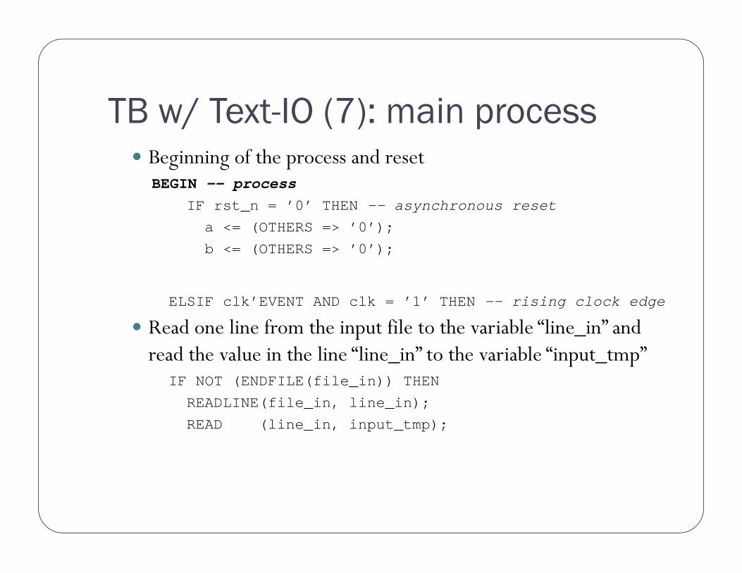
TB w/ Text-IO (7): main process Beginning of the process and reset
BEGIN -- processIF rst_n = ’0’ THEN -- asynchronous reset
a <= (OTHERS => ’0’);
b <= (OTHERS => ’0’);
ELSIF clk’EVENT AND clk = ’1’ THEN -- rising clock edge
Read one line from the input file to the variable “line_in” and read the value in the line “line_in” to the variable “input_tmp”
IF NOT (ENDFILE(file_in)) THEN
READLINE(file_in, line_in);
READ (line_in, input_tmp);

TB w/ Text-IO (8): handle I/O line by line “input_tmp” is fed to both inputs of the DUT
a <= CONV_UNSIGNED(input_tmp, 3); -- old skool conversionb <= CONV_UNSIGNED(input_tmp, 3);
The response of the DUT is converted to integer and fed to the variable “output_tmp”
output_tmp := CONV_INTEGER(y);
The variable “output_tmp” is written to the line “line_out” that is written to the file “file_out”
WRITE (line_out, output_tmp);WRITELINE(file_out, line_out);
At the end of the input file the note “End of file!” is givenELSEASSERT FALSEREPORT "End of file!"SEVERITY NOTE;
END IF;

TB w/ Text-IO (9): sim results Simulation:
Now, the designer can prepare multiple test sets for certain cornercases (positive/negative values, almost max/min values, otherwiseinteresting) . However, the VHDL is not modified.
This version does not check the response yet.
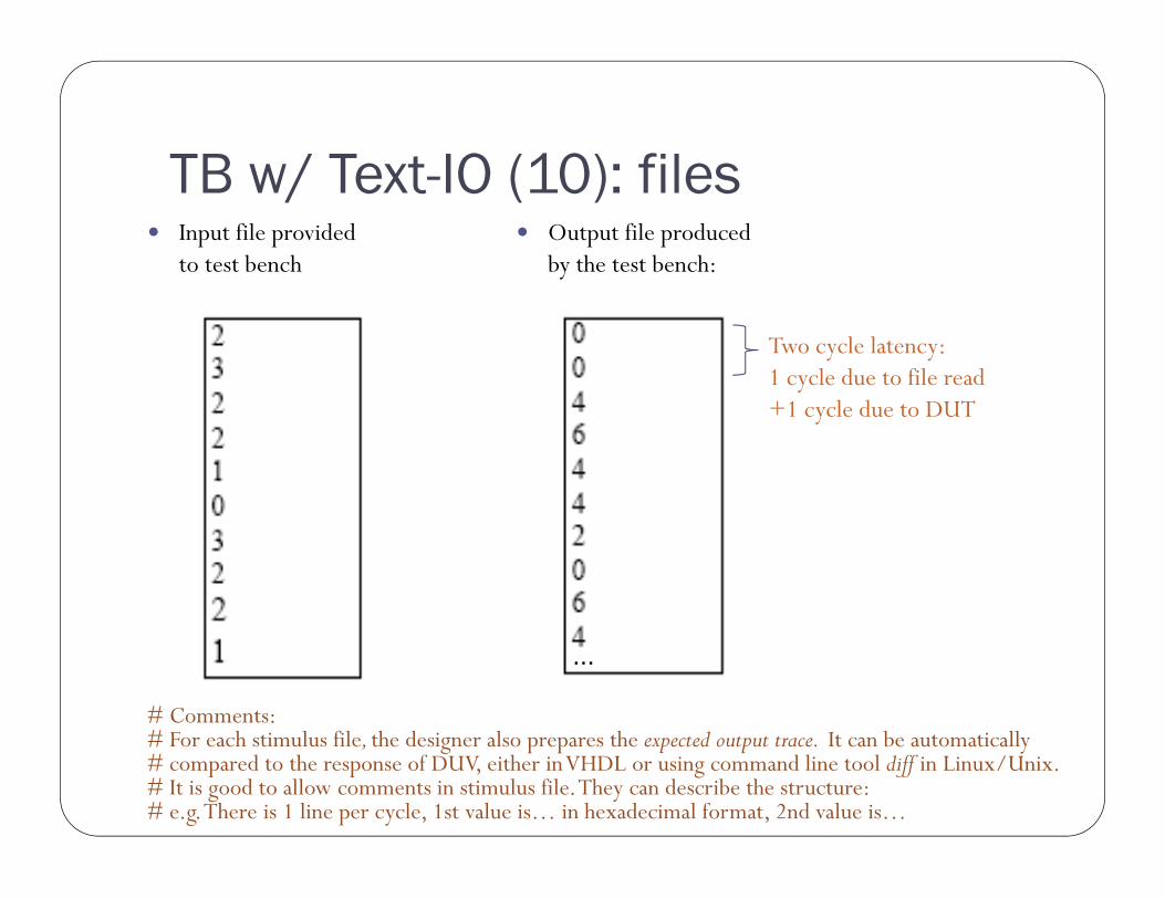
TB w/ Text-IO (10): files Output file produced
by the test bench: Input file provided
to test bench
Two cycle latency:1 cycle due to file read+1 cycle due to DUT
...
# Comments:# For each stimulus file, the designer also prepares the expected output trace. It can be automatically# compared to the response of DUV, either in VHDL or using command line tool diff in Linux/Unix.# It is good to allow comments in stimulus file. They can describe the structure: # e.g. There is 1 line per cycle, 1st value is… in hexadecimal format, 2nd value is…

Use headers in input and output files Fundamental idea is to have
many input, referenceoutput, and result files Provide clear links
between these
Use headers!
E.g. input file # File: ov1_in.txt
# Purpose: Test overflow…
# Designer: Xavier Öllqvist
# Date: 2013-12-24 16:55:02
# Version: 1.1
# Num of cases: 430
# Line format: hexadecimal…
E.g. DUV output log couldprovide summary
# File: ov1_out.txt
# Input File: ov1_in.txt
# Time: 2014-02-03 14:24:33
# User: xavi
# Format:…
0
0
4…
# Sim ends at: 100 ms
# Num of cases: 430
# Errors: 0
# Throughput: 25.4 MB/s
. . .

Text-I/O types supported by default READ and WRITE procedures support Bit, bit_vector Boolean Character Integer Real String Time Source: textio_vhdl93 library, Altera
For other types, use txt_util.vhd fromhttp://www.stefanvhdl.com/vhdl/vhdl/txt_util.vhd
Hint: std_logic_1164, numeric_std etc are all available in VHDL, you can always check those for reference.

Test prints Printing a constant text string is easy inside processes, just
report what’s going onprocess (…)…report (”Thunder!”);
Some people useassert false report ”Bazinga!” severity…
Whereas some prefer
write (line_v, string'(”Halibatsuippa!”));
writeline(output, line_v); -- output is a reserved word for stdout
On the other hand, signal and variable values are a bit tricky

Test print examples (2) Write function example for 1-bit std_logic
write (line_v, string'(“Enable “));
write (line_v, to_bit(en_r));
writeline(output, line_v);
Integers and enumerations can be converted to string, for examplewrite (line_v, string'(“I= “)& integer'image(5));
orreport “Value is “
& integer‘image(to_integer(unsigned(data_vec)));

Test print layout Default layout for report/assert uses two lines which is
somewhat inconvenient** Note: Thunder!
# Time: 60 ns Iteration: 0 Instance: /tb_tentti
Modify modelsim.ini and restart vsim; AssertionFormat = "** %S: %R\n Time: %T Iteration: %D%I\n"
AssertionFormat = "** %S: %R Time: %T %I\n"
Then# ** Note: Thunder! Time: 60 ns Instance: /tb_tentti
# ** Note: hojo hojo Time: 88 ns Instance: /tb_tentti
Me likes! For example, using grep is much much easier now

File handling in VHDL’87 and ’93 [HARDI VHDL handbook's page 71]--VHDL’87:
FILE f1 : myFile IS IN ”name_in_file_system”;
FILE f2 : mySecondFile IS OUT ”name_in_file_system”;
-- VHDL’93:
FILE f1 : myFile OPEN READ_MODE IS ”name_in_file_system”;
FILE f2 : mySecondFile OPEN WRITE_MODE IS ”name_in_file_system”;
Input files may be written compatible with both VHDL’87 and VHDL’93, but for output files that is not possible:
-- Declaration of an input file both for VHDL’87 and VHDL’93
FILE f : myFile IS ”name_in_file_system”;
The predefined subprograms FILE_OPEN and FILE_CLOSE do not exist in VHDL’87.

Same Test Bench for Different Designs Architecture of the DUT can be changed Should always be the objective Creating a separate testbench for gate-level will likely introduce
bugs in TB

Golden Design DUT is compared to the specification i.e. the golden design.
Something that is agreed to be correct E.g. Non-synthesizable model vs. fully optimized, pipelined,
synthesizable DUT
Special care is needed if DUT and Golden Design have different timing
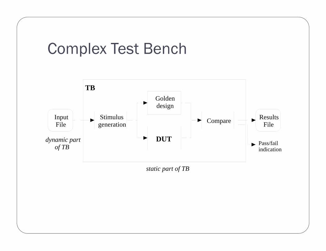
Complex Test Bench
Goldendesign
CompareStimulusgeneration
InputFile
ResultsFile
TB
Pass/failindication
static part of TB
dynamic partof TB
DUT
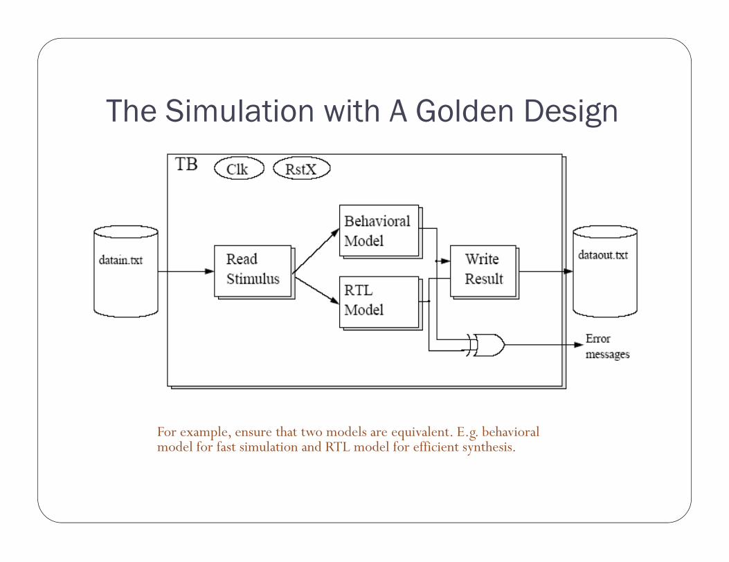
The Simulation with A Golden Design
For example, ensure that two models are equivalent. E.g. behavioral model for fast simulation and RTL model for efficient synthesis.

VHDL TESTBENCH
Example of golden design testbench Often, a system is first modeled with software and then parts are hardware
accelerated Software implementation serves as a golden reference
E.g. Video encoder implemented with C, motion estimation accelerated
Tends to be quite slow.
C Video encoder
Read, convert, interfacestimuli
DUVMotion Est
C motion estimation
Compareresult
Feedback for the video encoder
OK?
Foreign language interface (FLI)

Autonomous test bench Does not need input file stimulus Determines the right result ”on-the-fly” Very good for checking if simple changes or optimizations broke the design Note that some (pseudo-)randomization on the stimuli must be done in order
to make sure that the unusual cases are covered Check the code, statement, and branch coverages!
DUT
Result calculation
CompareStimulus generation
TB
Pass/failindication
static part of TB
Stimulus configuration

Design Flow

Example and conclusions

The test scenario DUV system-level interconnection network between IP
blocks (CPUs, memories, accelerators…)
TB must be expandable to very large configurationsIP/Test
Agent
IP / Test
Agent
Test Agent
IP / Test
Agent
INTERCONNECTION
…
…
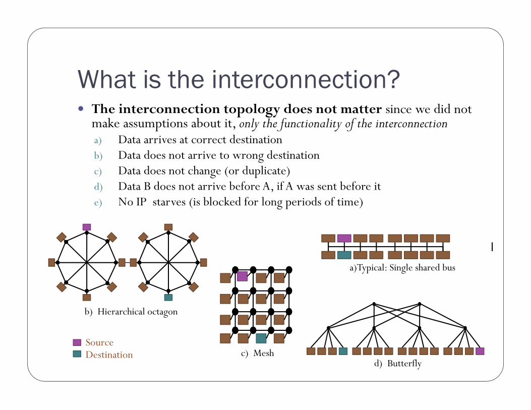
What is the interconnection? The interconnection topology does not matter since we did not
make assumptions about it, only the functionality of the interconnectiona) Data arrives at correct destinationb) Data does not arrive to wrong destinationc) Data does not change (or duplicate)d) Data B does not arrive before A, if A was sent before ite) No IP starves (is blocked for long periods of time)
a)Typical: Single shared bus
c) Meshd) Butterfly
b) Hierarchical octagon
SourceDestination

Example: verifying an interconnection Tested interconnections delivers data from a single source to destination Same principle, same IP interface, slightly different addressing
Note that the only the transferred data integrity is important, not what itrepresents - Running numbers are great!
The testbench should provide a few assertions (features a-d in prev slide) When checking these assertions, you also implicitely verify the correctness of the
interface! i.e. read-during-write, write to full buffer, write with an erroneous command
etc. All of these can be fairly simply accomplished with an automatic test bench
requiring no external files TB is pseudo-random numbers (*)
Longer simulation provides more thoroughness The same run can be repeated because it is not really random (*) Note that even if pseudo-random sequence is exactly the same, any change in
DUV timing might mask out the bug in later runs

Test Agent
Sender
Hierarchical interconnection testbench Separate the stimuli and
verification Sender configuration per test
agent-basis• Burst length (ie.sending
several data in consecutiveclock cycles)
• Idle times• Destination
• Initial values:• Seed for counter / LFSR• Number of components• Addresses of the components
• Sender and Receiver• Counter or PRNG needed for
each source and/ordesstination!
• (PRNG = pseudo-randomnumber generator)
Counter or PRNG Protocol
logicConfigu-ration
enable
interconnect
Receiver
Counter or PRNG Protocol
logic
Compare
enable
interconnect
Initial values
error
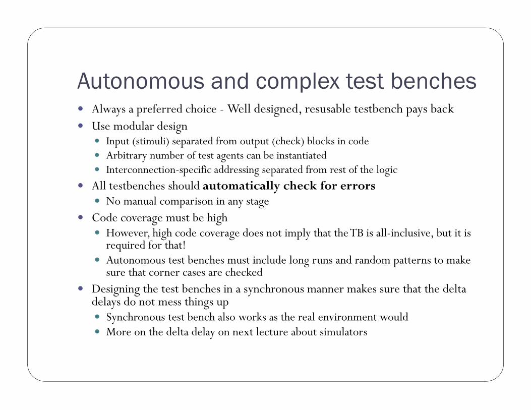
Autonomous and complex test benches Always a preferred choice - Well designed, resusable testbench pays back Use modular design
Input (stimuli) separated from output (check) blocks in code Arbitrary number of test agents can be instantiated Interconnection-specific addressing separated from rest of the logic
All testbenches should automatically check for errors No manual comparison in any stage
Code coverage must be high However, high code coverage does not imply that the TB is all-inclusive, but it is
required for that! Autonomous test benches must include long runs and random patterns to make
sure that corner cases are checked Designing the test benches in a synchronous manner makes sure that the delta
delays do not mess things up Synchronous test bench also works as the real environment would More on the delta delay on next lecture about simulators

Example VHD: Traffic light test bench Statement, Branch, Condition and expression coverage 100% However, the test bench is not perfect! Example VHDL code shown (available at web page) General test bench form
begin -- tb
-- component instantiationDUV : traffic_light ...
input : process (clk, rst_n)begin -- process input...end process input;
output: process (clk, rst_n)begin -- process output...end process output;
Clock generationReset generation
end tb;

Synthesizable testbenches Synchronous, synthesizable test benches are a good practice if e.g.
the design includes clock domain crossings
Can be synthesized to a FPGA and tested in a real environment
Run-time error checking facilities to a real product may be extracted from the test bench easily
Then, assertion should be written this way:If (a > b) then
assert false ”error” …error_out(0) <= ’1’;
End if;
Or one can make own assertions for simulation and synthesis, e.g.Assert_gen(cond, level, error_sig);
In simulation, regular assertion, in synthesis, assigns to error_sig
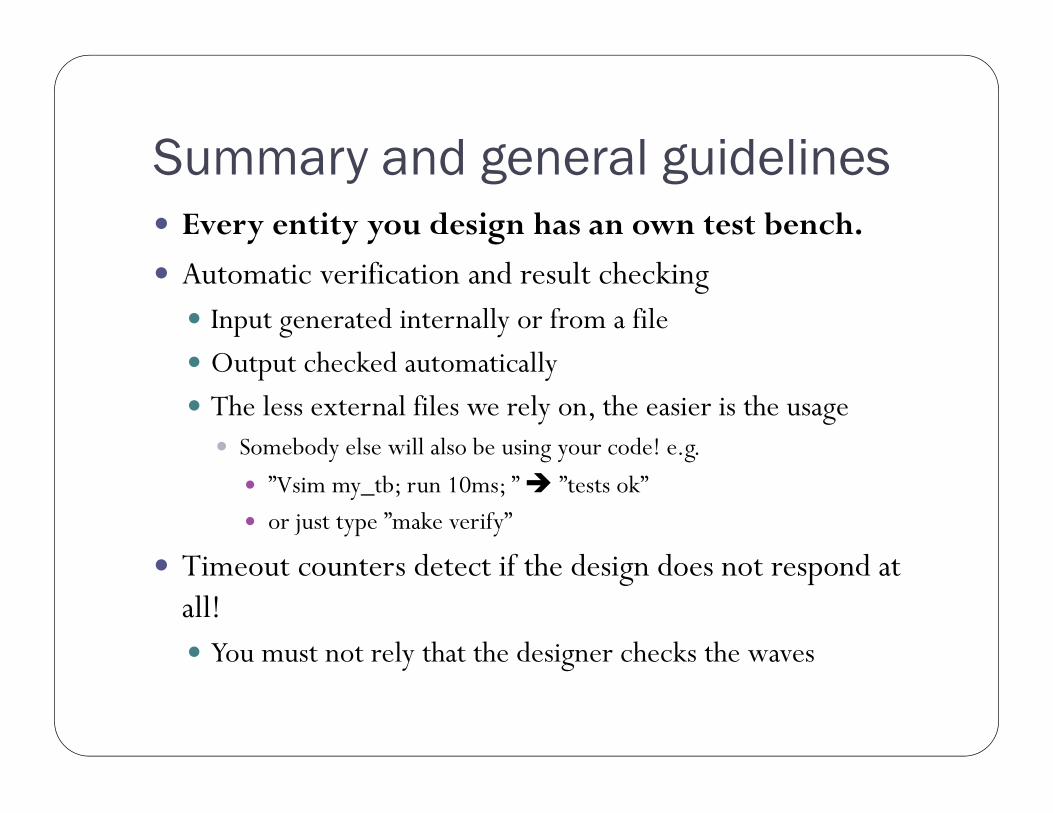
Summary and general guidelines Every entity you design has an own test bench.
Automatic verification and result checking Input generated internally or from a file Output checked automatically The less external files we rely on, the easier is the usage Somebody else will also be using your code! e.g.
”Vsim my_tb; run 10ms; ” ”tests ok” or just type ”make verify”
Timeout counters detect if the design does not respond at all! You must not rely that the designer checks the waves

Extra

Correct bugs early Earlier the bugs fixed, the cheaper
Shorter design time smaller personel cost bigger market share
[B.W. Boehm, Software Engineering, IEEE Trans. Computers, 1976]
(log scale)
Worst case: already sold devices must be returned to manufacturer
Similarly, a bug in spec affects all other phases
May require changes in many places

Sources of failures
[P. Magarshack, SoC at the heart of conflicting, Réunion du comité de pilotage (20/02/2002),trendshttp://www.comelec.enst.fr/rtp_soc/reunion_20020220/ST_nb.pdf]
Most logical errors could be found before fabrication

Verification methods (1)1. Reviews come in 2 flavors
1. Specification reviews are especially useful Remove ambiguities Define how certains aspects of specification are recognized and
analyzed in final product Be sure to capture customer’s wishes correctly
2. Code review Designer explains the code to others Surprisingly good results even if others do not fully undestand Good for creating clear and easy-to-understand code Limited to small code sizes Define and adopt coding guidelines
Automated checkers (lint) tools available ”I’ve made many many product mistakes over the years. I should at
least help make sure we make new mistakes this time around” Eric Hahn on code reviews

Verification methods (2)2. Simulation-based
Behavior is simulated in simulatorprogram
Relies on test data Testbench creation takes time
Cannot prove correctness Slow, 100Hz - 100 kHz Many levels of abstractions (algorithm
vs. RTL vs. gate-level) Availability of models might be a
problem Most widely used method System simulation in lecture 5
Example 1: SystemC TLM + visualization
Example 2: RTL
Example 3: Transistor-level

Verification methods (2)3. HW emulation
(Part of the) system is executed on programmable HW (FPGA) ”FPGA protoype”, no mask costs as in ASIC
proto Nearly real-time execution (~1 MHz -100
MHz) But no regard of real logic delays!
Can connect to real external HW, such as radio
Rough GUI testing possible Setup time may be long, e.g. few hours
Needs synthesis and place-and-route Traditionally quite expensive systems Reduced visibility compared to simulation Relies on test data, cannot prove correctness
Example: BEE4 system contains 4 Xilinx Virtex-6 LX550 FPGAs (20 Million system gates per FPGA)
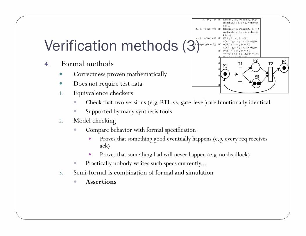
Verification methods (3)4. Formal methods
Correctness proven mathematically Does not require test data1. Equivcalence checkers
Check that two versions (e.g. RTL vs. gate-level) are functionally identical Supported by many synthesis tools
2. Model checking Compare behavior with formal specification
Proves that something good eventually happens (e.g. every req receivesack)
Proves that something bad will never happen (e.g. no deadlock) Practically nobody writes such specs currently...
3. Semi-formal is combination of formal and simulation Assertions

Levels of verification Level 0: Designer/macro, lowest level
Verification done by the designer (one who wrote the VHDL) Ensures that the design will load into simulator and that basic
operations work Often many changes in specification expected at this level Small block size, perhaps just a single HDL file, suitable also for formal
verification L1: Unit/core
Combines few low-level blocks together, DMA, ALU… More stable interfaces and functions compared to level 0 Test suite remains mostly unchanged
Reusable component (a core) necessitates more thorough verification Pro: Once verified, works always Con: Can be used in arbitrary environment, hard to verify all corner cases

Levels of verification (2) L1: Unit/core cntd Most important level for functional verification Q: How to gain customer’s confidence when selling core? A: Well-defined verification process, regression suite, proper
documentation, coverage reports, good reputation based on previous cores…
Level 2+: Chip, Board, System Multiple units, stable interfaces possibly some glue logic
Some functions cannot be verified a unit level For example, reset and start-up sequence
Interaction rather than particular functions are important at system level
Choose the lowest possible level Always choose the lowest level that completely contains the
targeted function Smallest state space, fast simulation 79% of bugs were found at BLOCK LEVEL [S. Switzer, Using
Embedded Checkers to Solve Verification Challenges, Designcon, 2000]
Each verifiable piece should have its own specification document Every VHDL entity must have its own testbench, at the least the
simple macro-level TB New and/or complex functions need extra focus Bugs seldom live alone Controllability and observability define the correct level The lower the level, the more control/visibility
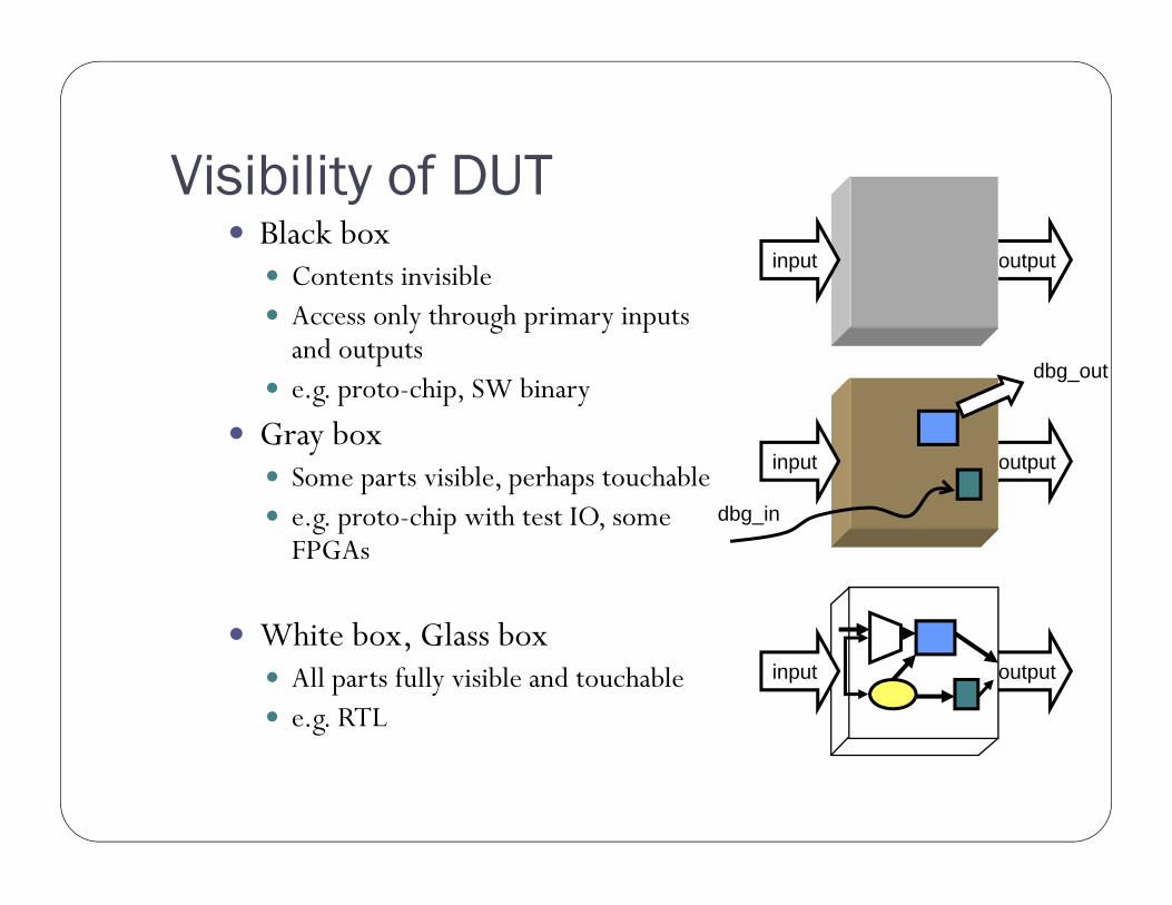
Visibility of DUT Black box
Contents invisible Access only through primary inputs
and outputs e.g. proto-chip, SW binary
Gray box Some parts visible, perhaps touchable e.g. proto-chip with test IO, some
FPGAs
White box, Glass box All parts fully visible and touchable e.g. RTL
outputinput
outputinput
outputinput
dbg_out
dbg_in

Bug-free behavior not guaranteed [M. Keating, Toward Zero-Defect Design: Managing Functional Complexity in the Era of Multi-Million-Gate Design Architecture, DCAS '05]

Random test input Good for finding corner cases
Easy to produce, allow large test vector sets Luckily, pseudo-random number generators produce same series if seed is same
Running numbers are sometimes enough!
Can generate random inputs to file reproducible (but space-hungry)
Randomness makes it harder to track error source output with running numbers: 1,2,3,4,888,6,7...
output with random data: 701,123,-987,2,3,4,5,..
Should not be usedwithout test caseswith ’known values’
[S. Taylor, DAC 1998]
Repeating tests Same error must be repeated to see if fix works
Same test data, same timing
Automated test generation
Must ensure that ”fix” does not break any other part of systemAutomated checking Manual checking suitable only for TB creation
Preferably same TB during the design refinement E.g. RTL and gate-level use same TB
Keep all the test cases that have failed Already fixed errors sometimes reappear later
Partition test cases into smaller sets