lec. 07 mixture preparation+gdi - massachusetts institute …web.mit.edu/2.61/www/lecture notes/lec....
TRANSCRIPT

1
SI Engine Mixture Preparation
1. Requirements
2. Fuel metering systems
3. Fuel transport phenomena
4. Mixture preparation during engine transients
5. The Gasoline Direct Injection engine
MIXTURE PREPARATION
Fuel Air
EGR
Engine
Fuel Metering
AirMetering
EGRControlMixing
CombustibleMixture
2
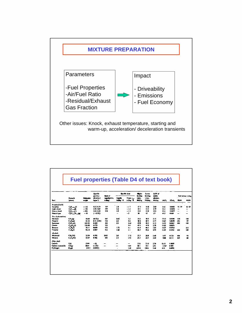
MIXTURE PREPARATION
Parameters
-Fuel Properties-Air/Fuel Ratio-Residual/Exhaust Gas Fraction
Impact
- Driveability- Emissions- Fuel Economy
Other issues: Knock, exhaust temperature, starting andwarm-up, acceleration/ deceleration transients
Fuel properties (Table D4 of text book)
3
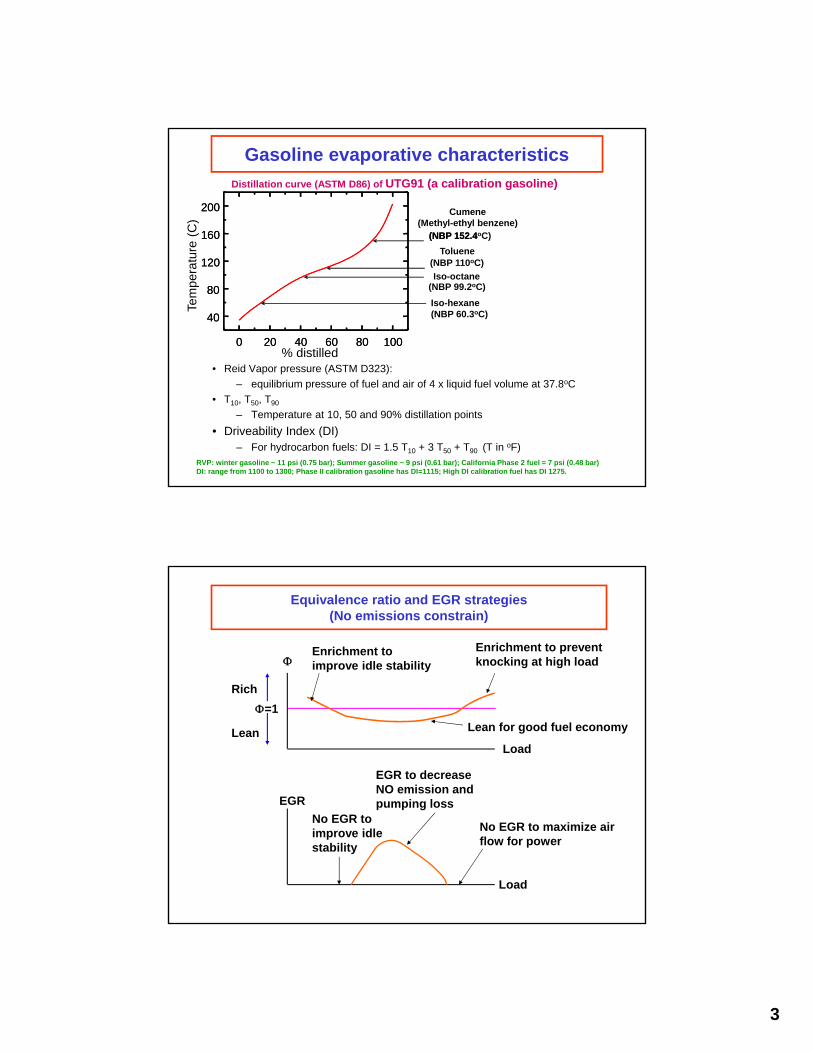
Gasoline evaporative characteristics
• Reid Vapor pressure (ASTM D323):
– equilibrium pressure of fuel and air of 4 x liquid fuel volume at 37.8oC
• T10, T50, T90
– Temperature at 10, 50 and 90% distillation points
• Driveability Index (DI)– For hydrocarbon fuels: DI = 1.5 T10 + 3 T50 + T90 (T in oF)
0 20 40 60 80 100
40
80
120
160
200Te
mpe
ratu
re (
C)
% distilled
(NBP 152.4
Toluene(NBP 110oC)
(NBP 99.2oC)
0 20 40 60 80 100
40
80
120
160
200
Distillation curve (ASTM D86) of UTG91 (a calibration gasoline)
(NBP 152.4oC)
Iso-octane
Cumene(Methyl-ethyl benzene)
Iso-hexane(NBP 60.3oC)
RVP: winter gasoline ~ 11 psi (0.75 bar); Summer gasoline ~ 9 psi (0.61 bar); California Phase 2 fuel = 7 psi (0.48 bar)DI: range from 1100 to 1300; Phase II calibration gasoline has DI=1115; High DI calibration fuel has DI 1275.
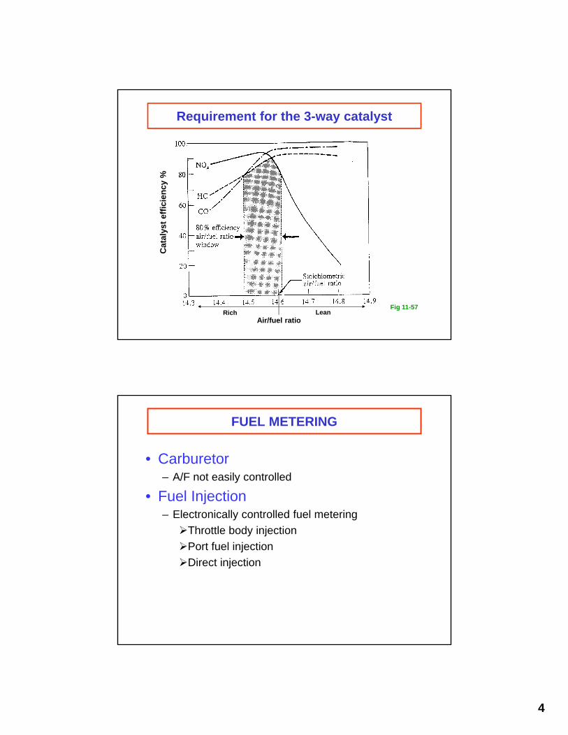
Equivalence ratio and EGR strategies(No emissions constrain)
=1
Rich
Lean
Load
Enrichment to prevent knocking at high load
Enrichment to improve idle stability
Lean for good fuel economy
EGR
EGR to decrease NO emission and pumping loss
No EGR to maximize air flow for power
No EGR to improve idle stability
Load
4
Requirement for the 3-way catalyst
Air/fuel ratioRich Lean
Cat
alys
t ef
fici
ency
%
Fig 11-57
FUEL METERING
• Carburetor– A/F not easily controlled
• Fuel Injection– Electronically controlled fuel metering
Throttle body injection
Port fuel injection
Direct injection
5
Injectors
PFI injectors
• Single 2-, 4-,…, up to 12-holes
• Injection pressure 3 to 7 bar
• Droplet size:– Normal injectors: 200 to 80 m
– Flash Boiling Injectors: down to 20 m
– Air-assist injectors: down to 20 m
GDI injectors
• Shaped-spray
• Injection pressure 50 to 150 bar
• Drop size: 15 to 50 m
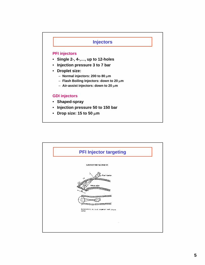
PFI Injector targeting
6
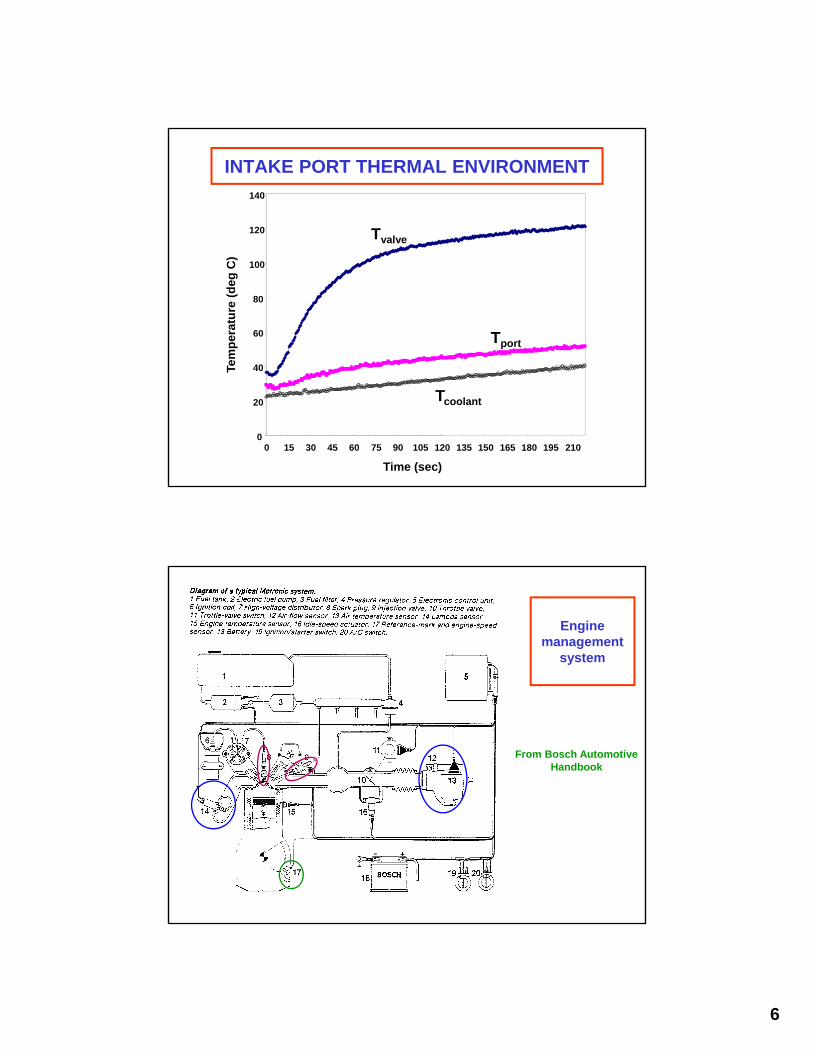
INTAKE PORT THERMAL ENVIRONMENT
0
20
40
60
80
100
120
140
0 15 30 45 60 75 90 105 120 135 150 165 180 195 210
Time (sec)
Tem
per
atu
re (
deg
C)
Tvalve
Tport
Tcoolant
Engine management
system
From Bosch Automotive Handbook
7
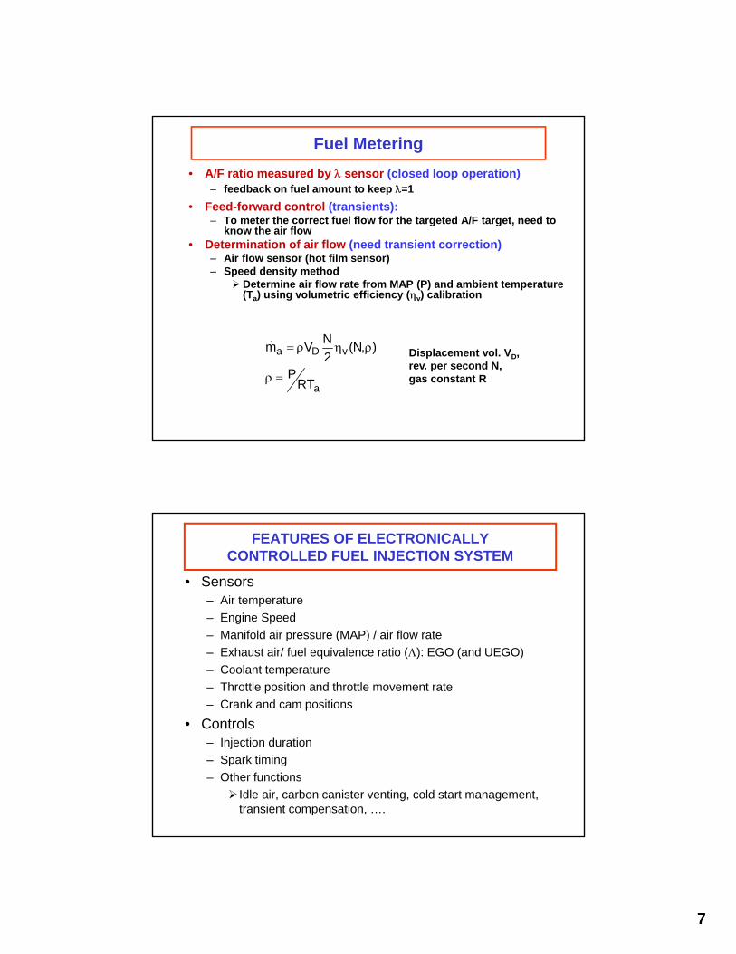
Fuel Metering
• A/F ratio measured by sensor (closed loop operation)– feedback on fuel amount to keep =1
• Feed-forward control (transients):– To meter the correct fuel flow for the targeted A/F target, need to
know the air flow• Determination of air flow (need transient correction)
– Air flow sensor (hot film sensor)– Speed density method
Determine air flow rate from MAP (P) and ambient temperature (Ta) using volumetric efficiency (v) calibration
a
vDa
RTP
),N(2
NVm
Displacement vol. VD,rev. per second N,gas constant R
FEATURES OF ELECTRONICALLYCONTROLLED FUEL INJECTION SYSTEM
• Sensors– Air temperature
– Engine Speed
– Manifold air pressure (MAP) / air flow rate
– Exhaust air/ fuel equivalence ratio (): EGO (and UEGO)
– Coolant temperature
– Throttle position and throttle movement rate
– Crank and cam positions
• Controls– Injection duration
– Spark timing
– Other functions
Idle air, carbon canister venting, cold start management, transient compensation, ….
8
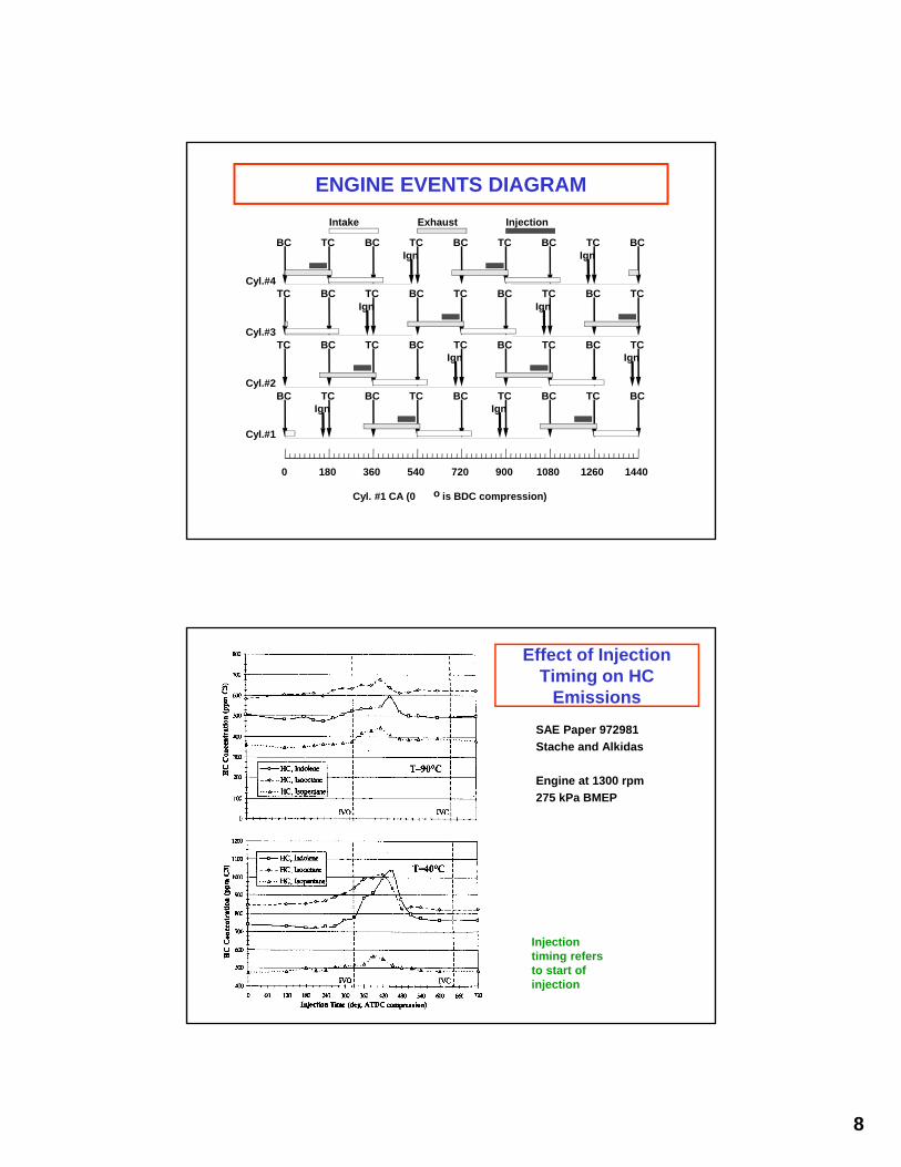
ENGINE EVENTS DIAGRAM
0 180 360 540 720 900 1080 1260 1440
Cyl. #1 CA (0 o is BDC compression)
Cyl.#1
Cyl.#2
Cyl.#3
Cyl.#4
BC BC BC BC BCTC TC TC TC
TC TC TC TC TCBC BC BC BC
TC TC TC TC TCBC BC BC BC
BC BC BC BC BCTC TC TC TC
Intake Exhaust Injection
Ign Ign
Ign Ign
Ign Ign
Ign Ign
Effect of Injection Timing on HC
Emissions
SAE Paper 972981
Stache and Alkidas
Engine at 1300 rpm
275 kPa BMEP
Injection timing refers to start of injection
9
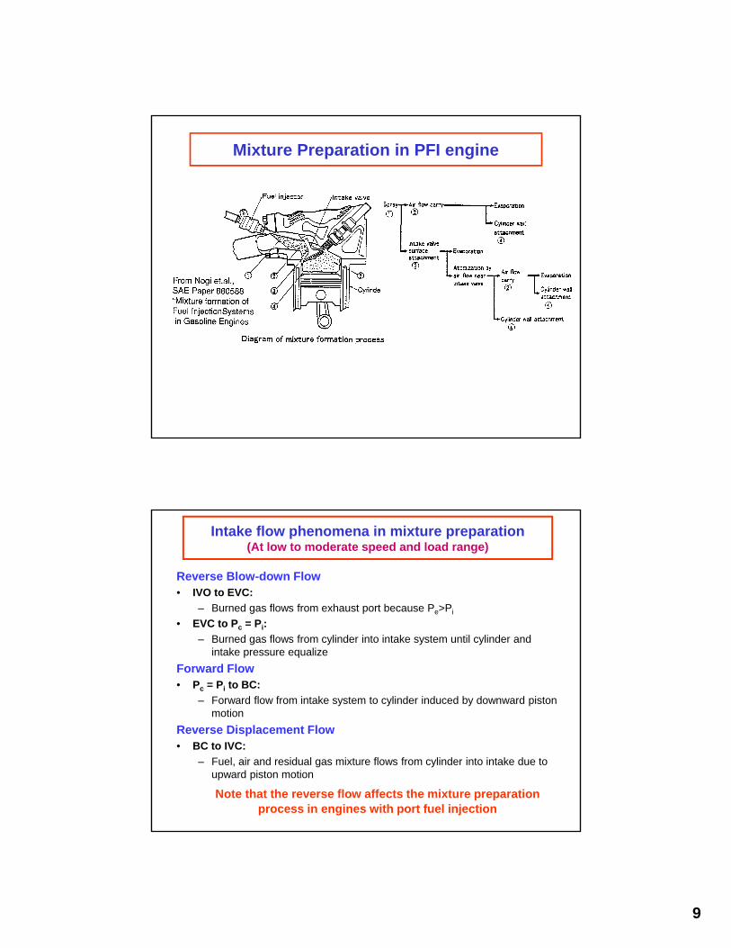
Mixture Preparation in PFI engine
Intake flow phenomena in mixture preparation(At low to moderate speed and load range)
Reverse Blow-down Flow• IVO to EVC:
– Burned gas flows from exhaust port because Pe>Pi
• EVC to Pc = Pi:
– Burned gas flows from cylinder into intake system until cylinder and intake pressure equalize
Forward Flow• Pc = Pi to BC:
– Forward flow from intake system to cylinder induced by downward piston motion
Reverse Displacement Flow• BC to IVC:
– Fuel, air and residual gas mixture flows from cylinder into intake due to upward piston motion
Note that the reverse flow affects the mixture preparation process in engines with port fuel injection
10
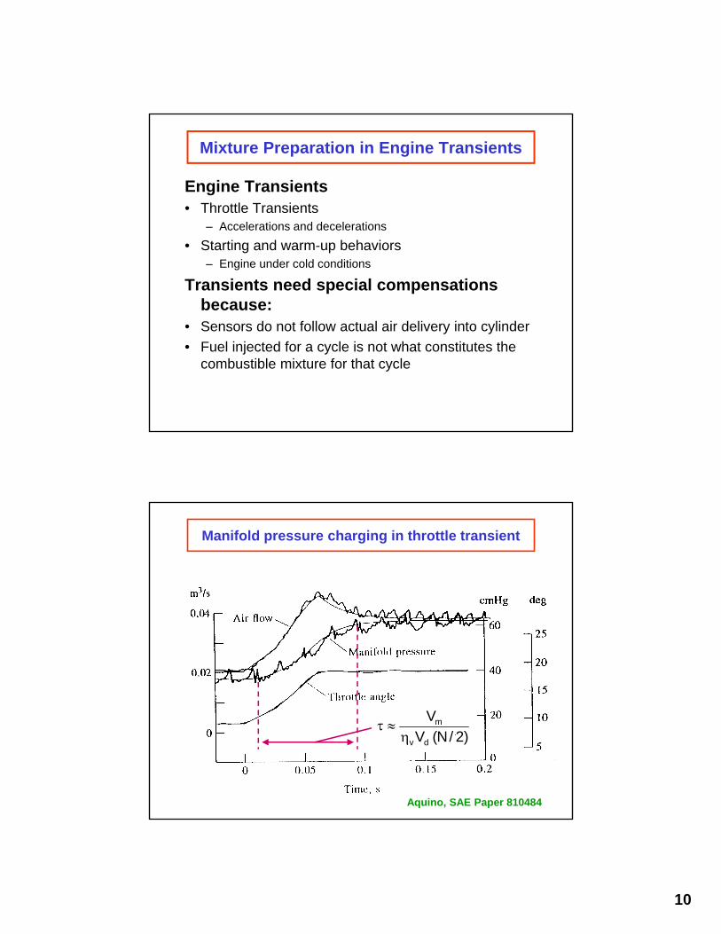
Mixture Preparation in Engine Transients
Engine Transients• Throttle Transients
– Accelerations and decelerations
• Starting and warm-up behaviors– Engine under cold conditions
Transients need special compensations because:
• Sensors do not follow actual air delivery into cylinder
• Fuel injected for a cycle is not what constitutes the combustible mixture for that cycle
Manifold pressure charging in throttle transient
Aquino, SAE Paper 810484
)2/N( V
V
dv
m

11
Fuel-Lag in Throttle Transient
puddle in mass Fuel M
cylinder to
ratedelivery Fuel m
rateflow fuel Injected m
Mmx)-(1 m
Mmx
dt
dM
f
c
f
ffc
ff
f
The x- Model
Fuel transient in throttle opening
Model prediction Observed results
Fig 7-28Uncompensated A/F behavior in throttle transient
cm
airm
12
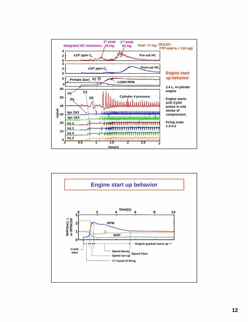
Engine start up behavior
2.4 L, 4-cylinderengine
Engine starts with Cyl#2 piston in mid stroke of compression
Firing order1-3-4-2
Integrated HC emissions:1st peak16 mg Total: 71 mg (SULEV:
FTP total is < 110 mg)
2nd peak55 mg
sig
nal
Pre-cat HC
Post-cat HC
x104 ppm C1
x104 ppm C1
Pintake (bar)x1000 RPM
(e) (f)
Cylinder 4 pressure
Ign 2&3
Ign 1&4
Inj 3
Inj 1
Inj 4
Inj 2
(a)
(b)
(c)
(d)
0 0.5 1 1.5 2 2.5 30
10
20
30
40
50
60
time(s)
0
2
4
0
2
4
0
2
Engine start up behavior
0 2 4 6 8 10
0
1
2
3
time(s)
MA
P(b
ar),
o
r R
PM
/100
RPM
MAP
Crankstart
1st round of firing
Speed run up
Speed decay
Engine gradual warm up
Speed Flare

13
Pertinent Features of DISI Engines
1. Precise metering of fuel into cylinder– Engine calibration benefit: better driveability and
emissions
2. Opportunity of running stratified lean at part load– Fuel economy benefit (reduced pumping work; lower
charge temperature, lower heat transfer; better thermodynamic efficiency)
3. Charge cooling by fuel evaporation– Gain in volumetric efficiency– Gain in knock margin (could then raise compression
ratio for better fuel economy)– Both factors increase engine output
Toyota DISI Engine (SAE Paper 970540)
0 1000 30002000 4000 5000
Engine speed (rpm)
Ou
tpu
t to
rqu
e
High pressure injector
Straight port
14
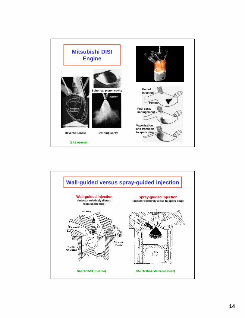
Mitsubishi DISI Engine
End of injection
Piston
Fuel spray impingement
Vaporization and transport to spark plugReverse tumble Swirling spray
Spherical piston cavity
(SAE 960600)
Wall-guided versus spray-guided injection
Wall-guided injection(injector relatively distant
from spark plug)
Spray-guided injection(injector relatively close to spark plug)
SAE 970543 (Ricardo) SAE 970624 (Mercedes-Benz)
15
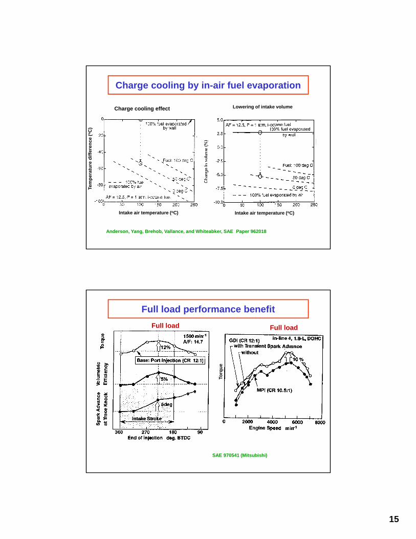
Charge cooling by in-air fuel evaporation
Intake air temperature (oC)Intake air temperature (oC)
Tem
per
atu
re d
iffe
ren
ce (
oC
)
Charge cooling effect Lowering of intake volume
Anderson, Yang, Brehob, Vallance, and Whiteabker, SAE Paper 962018
Full load performance benefit
Torq
ue
Full loadFull load
SAE 970541 (Mitsubishi)
16
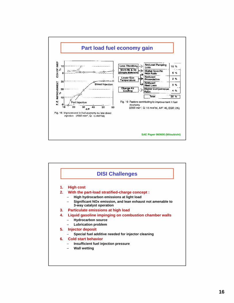
Part load fuel economy gain
SAE Paper 960600 (Mitsubishi)
DISI Challenges
1. High cost2. With the part-load stratified-charge concept :
– High hydrocarbon emissions at light load– Significant NOx emission, and lean exhaust not amenable to
3-way catalyst operation
3. Particulate emissions at high load4. Liquid gasoline impinging on combustion chamber walls
– Hydrocarbon source– Lubrication problem
5. Injector deposit– Special fuel additive needed for injector cleaning
6. Cold start behavior– Insufficient fuel injection pressure– Wall wetting

17
Comparison of cold start HC emissions(Koga, Miyashita, Takeda, and Imatake, SAE Paper 2001-01-0969)
Rel
ativ
e
Cumulative engine out HC in the first 10 seconds of cold-start
Significant particle numbers in cold start
SAE 2011-01-1219