learning reflexes for teleoperated ground-based rescue robots
TRANSCRIPT

LEARNING REFLEXES FOR TELEOPERATED
GROUND-BASED RESCUE ROBOTS
Major: Computer Science
April 2011
Submitted to the Office of Undergraduate Research Texas A&M University
in partial fulfillment of the requirements for the designation as
UNDERGRADUATE RESEARCH SCHOLAR
A Senior Scholars Thesis
by
MATTHEW MOSS
LEARNING REFLEXES FOR TELEOPERATED
GROUND-BASED RESCUE ROBOTS
Approved by: Research Advisor: Robin Murphy Director for Honors and Undergraduate Research: Sumana Datta
Major: Computer Science
April 2011
Submitted to the Office of Undergraduate Research Texas A&M University
in partial fulfillment of the requirements for the designation as
UNDERGRADUATE RESEARCH SCHOLAR
A Senior Scholars Thesis
by
MATTHEW MOSS

iii
ABSTRACT
Learning Reflexes for Teleoperated Ground-Based Rescue Robots. (April 2011)
Matthew Moss Department of Computer Science
Texas A&M University
Research Advisor: Dr. Robin Murphy Department of Computer Science
This thesis presents a system for shared autonomy, where a search and rescue robot uses
training data to create a "maintain balance" reflex to enable a robot to autonomously
stop, back up, or change configuration to avoid falling over as the operator drives it
through rubble. Currently, the operator is responsible for determining if the robot is in an
unsafe state and about to fall. Falling over often ends the mission for the robot. With a
"maintain balance" reflex, the operator can drive the robot with less risk of falling over.
This project required retrofitting an ASR/Inuktun Extreme variable geometry robot with
an Analog Devices ADXL335 3-axis accelerometer to provide inputs for a fall classifier
optimized by a genetic algorithm. The software system written in C# uses a
Subsumption Architecture, where the reflex takes priority over operator commands that
place the robot in danger. The developed system was tested over 3 trials, 2 with the
NIST Standard Test Method for Response Robots: Mobility: Terrain: Stepfields. 4
variants of the system and a control were compared for effectiveness. Over the 3 trials
each variant was tested with 45 starting configurations. Variants of the system

iv
demonstrated an 8% decrease in the probability of falling on a simple climbing stepfield,
and a 40% decrease on flat terrain. The results show that the primary mechanism for
reducing falls is backing up, which shows a 6% improvement over halting in terms of
fall probability. The small improvement reflects the lack of agility and sensing
limitations of the robot, the data suggests the classification algorithm was an appropriate
choice, as it responds to situations not captured by a simple physically based model. This
work is expected to be useful for other search and rescue robots; each type of robot
would have to be trained using the procedures described in this thesis.
v
NOMENCLATURE
CRASAR Center for Robot Assisted Search And Rescue
UGV Unmanned Ground Vehicle
VGTV Variable Geometry Tracked Vehicle

vi
TABLE OF CONTENTS
Page
ABSTRACT ....................................................................................................................... iii
NOMENCLATURE ............................................................................................................ v
TABLE OF CONTENTS ................................................................................................... vi
LIST OF FIGURES ........................................................................................................... vii
LIST OF TABLES ........................................................................................................... viii
CHAPTER
I INTRODUCTION ....................................................................................... 1
II METHODS .................................................................................................. 4
Starting equipment .......................................................................... 4 Developing the controller ................................................................ 9 Experiment process ....................................................................... 16 III RESULTS .................................................................................................. 21
Genetics training ........................................................................... 21 Ideal climbing case ........................................................................ 22 Hill climbing with low noise case ................................................. 24 Flat carpeted surface case .............................................................. 26 IV DISCUSSION AND SUMMARY ............................................................ 28
Response type: Halt or reverse? .................................................... 28 Fall classifier: Distance based, velocity based, or nothing? .......... 30 Summary ....................................................................................... 31 REFERENCES .................................................................................................................. 33
CONTACT INFORMATION ........................................................................................... 34

vii
LIST OF FIGURES
FIGURE Page
1 Inuktun VGTV ExtremeTM, ©Inuktun Services Ltd ............................................ 5
2 Filtering Effects on Accelerometer Values ............................................................ 7
3 Controller Diagram .............................................................................................. 11
4 Inuktun Near Example Stepfield .......................................................................... 13
5 Ideal Climbing Stepfield ...................................................................................... 19
6 Low Hill with Some Noise Stepfield ................................................................... 20

viii
LIST OF TABLES
TABLE Page
1 Distance Function Weights .................................................................................. 22
2 Ideal Climbing Case, Completions, Averages ..................................................... 23
3 Ideal Climbing Case, Distance = 0", Averages .................................................... 23
4 Ideal Climbing Case, Distance = 27", Averages .................................................. 24
5 Hill Climbing Case, Distance > 20", Averages .................................................... 26
6 Flat Carpeted Surface Case, Averages ................................................................. 27

1
CHAPTER I
INTRODUCTION
The goal of this thesis is to explore and implement a method for adding reflexes to a
UGV. We will retrofit a CRASAR owned Inuktun VGTV ExtremeTM with a 3-axis
accelerometer to provide orientation estimation, and then apply artificial intelligence
techniques to develop a controller that will allow the robot to maintain its balance during
operation. We will then compare the effectiveness of the controller against the existing
direct control system in a constrained lab environment.
Ground-based robots are an attractive option for responding to certain classes of
manmade disaster, such as building collapses, chemical releases, and radiological
disasters. Such robots are able to search deep within hazardous environments while
providing information on survivor locations and environmental conditions. Effectively,
robots are able to extend the senses of responders without risking either humans or
canines [1].
These disaster environments provide significant operational challenges for robots.
Rubble provides a rough, uneven operating surface with many obstacles that need to be
overcome. These conditions make the use of wheeled robots infeasible. Additionally,
_______________ This thesis follows the style of IEEE Transactions on Robotics.

2
spaces in collapsed buildings typically provide poor clearance and freedom of movement
for small aerial vehicles. Current practice is to use teleoperated tracked robots with a
variable (polymorphic) geometry [1]. These robots are susceptible to several problems.
In particular we will focus on the problem of maintaining balance. Polymorphic robots
are vulnerable to falling over due to changing vehicle geometry, or due to a change in
orientation while surmounting an obstacle, or even accelerating forward too quickly. In
current practice a human operator is responsible for tracking and correcting this issue.
The operator is expected to remember the polymorphic shape (pose) of the robot and
relationship to gravity and then estimate visually whether the robot will fall over.
Effectively, the operator is responsible for providing balance to the robot.
The reliance on a human operator for reflexes is a major limit in deploying robots. The
operator typically cannot react quickly enough, is distracted, or has insufficient training
and experience with the robots to provide adequate reflexes. In addition, providing
reflexes for the robot serves as a distraction to the operator, making the operator less
effective at task execution. Finally, AI implemented reflexes stand to decrease the
amount of training and experience required for an operator to become proficient at
operating a robots.
Learning itself is not novel as it has been successfully applied to ground robots for
obstacle avoidance [2], walking with four legs [3], and with six legs [4]. However, none
of the past work considers applying learning to a robot designed for teleoperation.

3
Robots intended for teleoperation typically do not have the proprioceptive sensors
needed to dynamically measure and control their pose. By performing simple retrofits to
the robot sufficient sensing can be made available for learning to be applied.

4
CHAPTER II
METHODS
This chapter details the implementation strategy for adding reflexes to the robot. This
chapter includes information about the starting equipment, equipment capabilities, the
overall learning process, and the decisions made that influence the process. It concludes
with details of the experiments to be carried out, and the reasoning behind the
experiment conditions.
Starting equipment
A robot, pose estimator, and laptop are required.
Robot
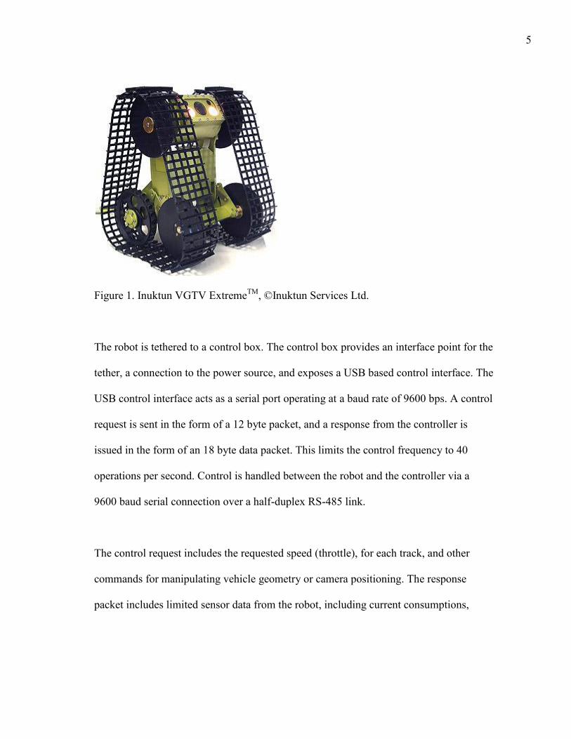
The base robot is an Inuktun VGTV ExtremeTM provided by CRASAR, as shown in
Figure 1. It is a water proof variable geometry tracked robot used in search, rescue, and
inspection operations. The robot uses a 30m long tether for all power and
communications needs. It includes limited proprioceptive sensors, including current
sensing on all major electrical components, temperature, raise angle, and a single axis
inclinometer. [5]
5
Figure 1. Inuktun VGTV ExtremeTM, ©Inuktun Services Ltd.
The robot is tethered to a control box. The control box provides an interface point for the
tether, a connection to the power source, and exposes a USB based control interface. The
USB control interface acts as a serial port operating at a baud rate of 9600 bps. A control
request is sent in the form of a 12 byte packet, and a response from the controller is
issued in the form of an 18 byte data packet. This limits the control frequency to 40
operations per second. Control is handled between the robot and the controller via a
9600 baud serial connection over a half-duplex RS-485 link.
The control request includes the requested speed (throttle), for each track, and other
commands for manipulating vehicle geometry or camera positioning. The response
packet includes limited sensor data from the robot, including current consumptions,

6
limited pose information, temperature, and voltage. The response packet also includes
the state of the control interface, such as joystick position and button presses.
Pose estimator
The pose estimator works by wirelessly transmitting raw accelerometer readings to the
controlling laptop. The control software on the laptop is in turn responsible for
performing filtering and transformation of the signal into more relevant values.
The pose estimator is powered by 4 AA batteries, and is secured to the robot by Velcro.
It uses an Atmel ATTiny85 to read analog values from an Analog Devices ADXL335 3-
axis accelerometer configured with and read at a 50Hz sampling bandwidth. The
accelerometer readings are packetized, and sent at 9600 bps to an XBee transmitter. The
data is transmitted wirelessly at 250 kbps to a listening XBee, and sent at 9600 bps from
the XBee receiver to an FTDI USB to TTL Serial cable, which is in turn read by the
control software listening on the corresponding serial port.
For each axis of the accelerometer 11 8-bit values are read serially, and the median value
from these readings is taken as the „raw‟ value for that axis. This median reading
approach should filter out the majority of ADC noise. Each axis reading sequence occurs
over the course of 1ms. Readings are taken serially because the microcontroller uses a
single multiplexed ADC, and rapid switching between inputs could lead to more
electrical noise in readings.

7
Figure 2. Filtering Effects on Accelerometer Values. A low pass filter is used to remove
high frequency noise from the accelerometer signal, while maintaining adequate impulse
response time.
One problem encountered with using an accelerometer for pose estimation is sensor
noise. While the robot is running the tracks introduce a large amount of vibration into
the chassis. The magnitude of vibrations on flat terrain with no obstructions was
observed to be up to +/- 2g. To provide sufficiently accurate pose estimation the raw
values from each axis of the accelerometer are passed through a low pass filter with a
time constant of 0.1s. Figure 2 demonstrates the accelerometer readings during a fall,
before and after filtering. The low pass filter with 0.1s time constant was observed to be
a reasonable median between filtering out the relatively high frequency vibration while
preserving sudden changes in orientation.
-3
-2
-1
0
1
2
3
4
5
59
.31
59
.89
60
.46
61
.02
61
.56
62
.12
62
.69
63
.26
63
.84
64
.40
64
.96
65
.54
66
.10
66
.67
67
.23
67
.79
68
.37
68
.94
69
.51A
cce
lera
tio
n (
g)
Time (s)
Low Pass Filter Effects tc = 0.1s
Z
FZ

8
Wireless transmission was chosen due to a lack of materials. The robot platform includes
6 spare conductors in the tether, and a broken out connection for accessing those
conductors, but we did not have the connectors to access the spare conductor connection.
Wireless presents a problem while operating in rubble, where transmissions are typically
blocked by several feet of metal and concrete[1]. If this device were to be deployed, it
would need a sturdy, water proof housing for the electronics and to either tap into the
provided spare conductors on the tether, or provide an auxiliary tether.
One concern with this setup is the delay in getting readings from the accelerometer to the
software. The packet sent from the transmitter of the pose estimator is 7 bytes, and at
9600 baud each byte takes roughly 1ms to send. The microcontroller takes 7ms to send
data to the XBee. The XBee waits 5ms to packetize and send data. The data is sent at
250 kbps in the 2.4GHz spectrum. Once the packet is received, the data is transmitted
over 7ms to the laptop, and in turn to the control software, which is polling for data
every 20ms. This gives an average transmission time of around 25ms, not accounting for
any wait times due to wireless transmission interference. We do not currently have data
on how wireless interference may be affecting transmission delays, and it is a potential
variable that would be removed by using a tethered serial connection.

9
Developing the controller
This section describes the form of the control system, its general operation, and how the
controller is trained.
Anatomy of a fall
A fall occurs when a robot enters a state where the tracks lose good driving contact with
the ground. This can be better thought of as whenever the robot enters a state with phi,
the angle between the normal of the pose estimator and gravity, greater than 90o. In this
state, while the robot may be able to recover, doing so is difficult, with a chance of
recovering in an upside-down pose. This is generally caused by an unsafe shift in the
center of gravity of the robot.
An unsafe shift in the center of gravity occurs in several situations. One situation is
when accelerating quickly on a high friction surface while in a raised pose- this causes a
rotation backward as the tracks apply a torque when countering momentum, eventually
leading to a fall. Another situation occurs when climbing rubble: the robot does not have
enough power to climb some obstacles, so it needs to approach them with enough
forward momentum to pull itself over the obstacle. If the robot contacts the rubble at too
high a speed, or too high a raise angle, the forward portion of the robot will „jump‟, and
combined with the continuing forward speed of the motors, fall over backward. There
are also methods of falling sideways and forwards, which are beyond the scope of this
thesis.

10
Several variables influence whether or not a robot will fall. In all observed correctable
falls (falls due to operator action or inaction), the robot is in a relatively raised
configuration, moving forward. Based on this, lowering the robot‟s raise angle or
releasing the throttle, if done preventively, should decrease the probability of falls.
Modifying the raise angle sufficiently to change the probability of falling often takes
over 2 seconds. Most falls occur in the course of a single second, meaning that using the
raise angle as the controlled variable will only work if we can accurately predict falling
cases. Predicting falls at a time range of 2 seconds would require knowledge of the
environment, which our system does not have. Due to this, and limitations discussed in
Chapters 3 and 4, the level of prediction required to use the raise angle as the control
variable is not available, and thus throttle is the variable used to prevent falls.
Controller structure
The controller uses a subsumption architecture to enable protection behaviors. The
overall data and command flow is as shown in Figure 3. If a fall is considered imminent,
a fall response is enacted which will modify the throttle command. This command is
issued and merged into the flow of normal operator inputs, overriding any throttle
request by the operator.
The “Fall Likely” component maps the current state of the robot, including pose, into a
safe or unsafe value. If the robot is considered to be unsafe, a fall response is enacted.

11
The AI and learning component of this system is the mapping from states to a safe or
unsafe value.
Figure 3. Controller Diagram.
Learning process
Our system classifies a robot state as likely to fall if 10% of similar states in training data
were marked as falls. To determine similarity a state space distance function is defined
and optimized via a genetic algorithm. The genetic algorithm uses performance on a
training and testing data set to score candidate functions, and the best candidate is taken
and implemented for use in the classifier.
Classification process
Our system needs to find a mapping from the current robot state to the “is falling” value.
To do this we need a set of training states, the current state of the robot, and a means of
finding the similarity between states. Each state consists of the following inputs:
12
Orientation with respect to the dominant force (gravity and accelerations)
Average Angular Velocity on the pitch axis, over ¼ second.
Requested speed for both tracks
Current consumed by both tracks
Raise Angle
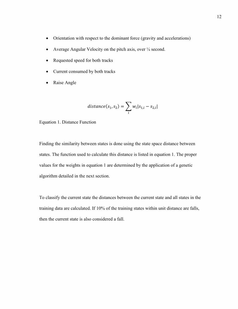
Equation 1. Distance Function
Finding the similarity between states is done using the state space distance between
states. The function used to calculate this distance is listed in equation 1. The proper
values for the weights in equation 1 are determined by the application of a genetic
algorithm detailed in the next section.
To classify the current state the distances between the current state and all states in the
training data are calculated. If 10% of the training states within unit distance are falls,
then the current state is also considered a fall.

13
Figure 4. Inuktun Near Example Stepfield.
Based on analysis of fall events we expect that the primary factors that cause a fall can
be tied to the angular velocities on the pitch axis, the raise angle, the throttle, and the
current orientation. Environmental differences (such as friction of the load bearing
surface) could be seen in track current consumption, but are not explored in this thesis.
Training process
Training is handled by capturing large quantities of training and testing data from test
runs in a simulated hazardous environment. The simulated hazardous environment is
built around stepfields[6], similar to what is shown in Figure 4. Stepfields allow for the
repeatable construction of difficult to navigate terrain. In the course of our experiments
we will use stepfields to create relatively simple, well defined climbing environments.
The training and testing data is automatically classified based on accelerometer readings
and controller inputs as “Not Fallen”, “Fallen”, and “Correcting”. The fallen and not

14
fallen classifications are for normal trainable states of data, and represent standard
operation of the robot. The correcting state is for the time between a robot falling, and
the next user control request. This period of time represents the user manually correcting
a fallen robot, during which several orientations which would be otherwise invalid are
experienced. To add an element of prediction to the fall classifier, states that occur ¼
second before a fall (phi > 90o) are also classified as falls.
A genetic algorithm is then used to optimize the weights of the distance finder. This
genetic algorithm scores a candidate set of weights by going through each testing state
and determining the classification given with the candidate weight set. The percent
correct classifications of falls and of non-falls are then combined with a 50% weight
given to each component. Due to the relative counts of fall states and not-fall states, this
typically means a fall classification is worth 10 non-fall classifications. Roulette wheel
selection on a population of size 16 with elitism for 2 individuals is then used for the
evolution process. Evolution continues until the user feels that a peak has been reached
(typically in less than 200 generations), and those peak weights are selected for use in
the classification component of the reflex controller.
Fall response
We will now detail the response that our controller will enact when falling. In a previous
section we determined that throttle is our only suitable control variable, but not how it
will be manipulated. In this section we will discuss the two response types that we are

15
considering, and their implications for an operator. Correctable falls in our testing
environment are always tied to the robot moving forward, meaning the robot always has
a forward throttle active. Our classification scheme states simply that if the user
continues moving forward they are likely to fall. Therefore, our response types are
centered on ceasing that movement. To this end we have two response types: halting
outright, and applying a reverse throttle.
Halting represents removing control from the operator temporarily. This is done in the
hope that the robot will correct itself out of a falling state if the halt is triggered before a
fall becomes critical. A fall is considered critical when the fall cannot be corrected by
simply ceasing forward movement. The human controller could then be alerted to the
probable fall, and allowed to take corrective action. The downside to this approach is
that to be useful it needs to be enacted before the fall enters the critical phase, which is
difficult to do due delays in the control loop.
Reversing represents not only removing operator control, but actively allowing the AI
subsystem to issue commands to the robot. Reversing as a response to falling was
developed during testing when halting was being triggered too late in the fall process to
be useful. The idea behind applying a reverse is that, while a fall may have entered the
critical stage, it has not yet become uncorrectable. Specifically, a short burst of a reverse
throttle will change the angular velocities enough that the robot is no longer in a fall
state. The downside to this approach is that false fall classifications tend to at best slow

16
the robot down, and at worst backtrack down from successfully conquered obstacles.
Another downside is that this approach may lead the robot into areas it should avoid,
such as reversing over a cliff. Therefore, reversing can be dangerous in certain
environments as the control system lacks the exteroceptive sensing required to prevent
such actions. Reversing also induces another falling risk. A reverse followed by a sudden
stop can be as bad as sudden acceleration in terms of inducing falls. To this end the
reverse response is implemented with a cool down phase, to slowly phase down the
throttle until it hits 0 again.
Each response is implemented such that it will be maximally activated for ½ second, to
prevent the control system from completely locking the operator out of the robot. An
override is also included in the control system. In addition, to prevent unnecessarily long
backtracking, the response is active for only twice the amount of time the robot was in a
fall classified state, with a minimum active time of 0.2 seconds.
Experiment process
For the purpose of this thesis we want to prove the viability of using an AI approach to
handling reflexes. For such an approach to be viable, it needs to be better than the
current system of no reflexes, and ideally would be better than a simple model based
reflex system.

17
We chose to simulate a user using our control system as a worst case operator. This
operator applies a constant forward throttle while the robot is in a predetermined fixed
raise configuration. We then test this against a simple physically based classifier and our
distance based classifier, with both the reverse and halting fall responses. We also test
this against a control group, the „no-reflex‟ controller, which does not attempt to classify
falls.
Physically based classifier
For comparison purposes we implement a simple physically based classifier. This
classifier takes the current phi and time averaged angular velocity, and calculates what
phi will be in ¼ second. If the projected phi value is greater than 90o then the current
robot state is classified as a fall.
Testing process
Each test set will take place on a specific step field configuration, with a specified
starting configuration consisting of a group of raise angles and throttle speeds. Each of
the 5 controllers will be tested on each starting configuration 5 times. These
configurations are enumerated, and then randomized for testing. The test proctor will
move the robot to a specified starting position, and indicate to the control agent that it
can begin the test. The control agent will then try to attain the desired raise angle. Due to
limitations of the control interface with the Inuktun, the attained raise angle is only
accurate to +/- 10o. Once the target raise angle is achieved to sufficient accuracy the

18
agent begins a timed application of forward throttle at the speed specified by the test run
parameters, with the specified reflex controller configuration active. If the robot falls, or
encounters an insurmountable obstacle, the test proctor indicates to the agent to stop the
test, and test statistics are then recorded. The robot is then reset for the next test run.
Environment configurations
For the purposes of testing we look at two stepfield configurations and one carpeted flat
surface for testing. Both stepfields consist of a small stepfield with 1.5” blocks leading
into a larger stepfield with 3” blocks. The larger stepfield always includes an
insurmountable wall along the outer edge to reduce the risk of falling damage to the
robot. If a robot reaches the rear wall of a stepfield course, it is considered to have
“completed” the course.

19
Figure 5. Ideal Climbing Stepfield. The first stepfield is intended to showcase responses in the simple climbing case. To that
extent the stepfield consists of two 1.5” climbs and one 3” climb. The simple climbing
stepfield uses the block configuration shown in Figure 5. Based on past experience, we
expect the majority of robot configurations to reach the large stepfield, where most will
fall or become stuck at the 3” climb. This is due largely to physical limitations in the
ability of certain raise configurations to climb the obstacle. This stepfield is also used for
training and testing data collection.

20
Figure 6. Low Hill with Some Noise Stepfield.
The testing configuration shown in Figure 6 makes the ideal climbing case more difficult
by include a 2 block hill on the small stepfield, and adding noise to the generated field
pattern. We expect the robot configurations to have more difficulty surmounting the first
hill, with an increased number of falls at this point, but to be otherwise similar to the
ideal climbing case.
Finally, the flat carpeted surface case is intended to test controller responses to rapid
acceleration from a dead stop. We expect all of the no-reflex controller runs in this
configuration to fall quickly, and expect the reflex based controllers to fare better.

21
CHAPTER III
RESULTS
This chapter details the numerical results from experiments carried out on an Inuktun
VGTVTM Extreme for the three test cases.
Genetics training
Training and Testing data were taken from the Ideal Climbing Stepfield, and run through
the genetic algorithm based optimizer. The training data consists of approximately 5
minutes of data with 18 falls, at varying raise angles. The testing data consists of
approximately 2 minutes of data with 6 falls. The relatively short period of data is due to
the time required to optimize weights when more data is collected, and the relatively
small number of falls that can be experienced on the ideal stepfield. In retrospect, we do
believe more testing data would have been appropriate.
After 200 generations the best scoring distance based classifier correctly classified 90%
of the testing data, with correct classification of 85% of falls, and 95% of non-falls. The
classifier generated the following weights:

22
Table 1 Distance Function Weights
Parameter Weight Value Range Relative Weight Current Angular Velocity 0.05 0-15 0.8 ¼ s Angular Velocity 0.5 0-10 5.0 Phi 2.39 0-Pi/2 3.8 Raise Angle 0.005 0-90 0.5 Throttle 0.018 -128 – 127 4.5 Track Current 0.005 0-255 1.2
Table 1 suggests that whether or not a given state is in danger of falling is based heavily
on the time averaged angular velocity, current throttle, and phi.
Ideal climbing case
The ideal climbing case consists of 3 well defined transitions: a 1.5” climb from lab
carpet to wooden blocks, a 1.5” climb from wooden blocks to wooden blocks, and a 3”
climb from wooden blocks to wooden blocks. These transitions are at 0”, 9”, and 27”
respectively.
Each reflex type is tested along 2 variables: full or half throttle (FT/HT in tables), and a
20, 45, or 70 degree target raise angle. This gives 6 possible starting configurations a
reflex type can be tested by, and each test was repeated 5 times, for a total of 30 tests for
each reflex type.

23
Table 2 Ideal Climbing Case, Completions, Averages
Reflex Type Time (s)- FT Time (s)- HT Corrections Count None 5.5 10.4 0 7
Velocity, Halt 8.5 9.9 2.1 7
Velocity, Reverse 7.3 10.1 2 6
Distance, Halt 6.0 9.9 1.6 7
Distance, Reverse 9.0 11.2 4.4 9
Table 2 shows data on the configurations that reached the end of the course. The only
robot configurations to successfully complete the course were those with a target raise
angle of 20; all other configurations were stopped by the large climb obstacle at 27”, or
earlier. This data indicates that the distance based reflex controller with reverse response
leads to more completions, though at a cost of increased completion time due to the
backtracking and speed loss that comes from the reverse response. All other reflex
controllers are on par with each other.
Table 3 Ideal Climbing Case, Distance = 0”, Averages
Reflex Type Time(s)- FT Time(s)- HT Corrections Fall Count None 2.3 3.0 0 9 Velocity, Halt 2.8 3.4 1.7 15 Velocity, Reverse 3.6 3.3 1.5 11 Distance, Halt 3.6 4.3 2.3 12 Distance, Reverse 4.3 6.1 4.9 7
Table 3 shows data on the configurations that fell at the first obstacle. We observe that
the distance based reflex controller with reverse response is less likely to fall than any
other reflex controller, and that all other reflex controllers fair worse than no the no-

24
reflex case. We also observe that all reflex controllers took more time to completely fall,
indicating that the controllers are able to delay a fall by varying amounts of time.
It is worth noting that two falls were recorded for each velocity based reflex controller at
the 9” obstacle. These were not included in Table 3 to prevent skewing of the time data.
Table 4 Ideal Climbing Case, Distance = 27", Averages
Reflex Type Time(s)- FT Time(s)- HT Corrections Fall Count Active Count
None 5.5 8.4 0 (67%) 14 21 Velocity, Halt 10.3 9.6 2.6 (50%) 7 14 Velocity, Reverse 13.8 10.4 5.5 (67%) 12 18 Distance, Halt 6.9 9.8 2.3 (61%) 11 18 Distance, Reverse 7.4 13.9 3.9 (61%) 14 23
Table 4 shows summary information on the falls surrounding the 3” climb obstacle,
where “Active Count” is the number of robot configurations that did not fall before this
point. This table indicates that each controller is performing on par or better than the no-
reflex case.
Hill climbing with low noise case
The hill climbing case consists of 2 stepfield hills with low noise added to the structures.
The first wall occurs at 6”, peaking at 3” above the plane, with a maximal 45o angle. The
second wall occurs at 27”, peaking at 3” above the plane.
25
Each reflex type is tested along 2 variables: full or half throttle, and a 20 or 40 degree
target raise angle. This gives 4 possible configurations a reflex type can be tested by, and
each test was repeated 5 times, for a total of 20 tests for each reflex type. The exclusion
of the 70o target raise angle and the slight decrease of the 45 o target raise angle were due
to the overall poor results these configurations had in the ideal climbing case. In the
ideal case, only 10% of the configurations with a target raise angle of 70 o overcame the
first obstacle.
The primary issues encountered in this test run were twofold. First, 10% of the robot
configurations would reach the transition from lab carpet to the stepfield, and stop,
unable to overcome the 1.5” climb. This was not observed in the first test, and may be
due to mechanical wear on the robot. Second, a further 30% of the configurations could
not climb the first wall- these configurations typically stopped on coming in contact with
the wall, possibly due to mechanical wear. Due to these issues, and the nature of how
data was recorded, data on the configurations that stopped at the first two obstacles
cannot be reliably disambiguated from data on configurations that fell at those first
obstacles. The only data that can be reliably extracted is the number of configurations to
reach the second hill.

26
Table 5 Hill Climbing Case, Distance > 20", Averages
Reflex Type Time(s)- FT Time(s)- HT Corrections Count None 6.0 7.6 0 7 Velocity, Halt 7.0 --- 4.5 2 Velocity, Reverse 12.2 11.7 2.4 5 Distance, Halt 6.0 12.6 1.5 2 Distance, Reverse 9.4 --- 6.5 2
Table 5 indicates that the no-reflex controller case outperformed all other controllers in
terms of reaching the final stage of the course. It should also be noted that the only
configuration to complete the course was based on a no-reflex controller. This data
assumes that the probability of getting stuck is uniformly distributed.
Flat carpeted surface case
The final test case looks at falls induced by a sudden acceleration from the stopped state.
This case looks at going from zero to full throttle with a raise angle of 90o, which has
been identified as the second major source of falls, along with attempting to climb
obstacles.

27
Table 6 Flat Carpeted Surface Case, Averages
Reflex Type Time(s) Corrections Completions None 1.7 0 0 Velocity, Halt 1.4 2 0 Velocity, Reverse 4.2 1.4 0 Distance, Halt 5.0 2.4 2 Distance, Reverse 3.5 2.4 2
Table 6 gives the data for the flat carpeted surface case. We note that the only
completions ending without a fall are the controllers using distance based classifiers. The
poor performance of the physically based classifiers may be due to a combination of
control loop delay and delays introduced by the low pass accelerometer filter, or due to
angular acceleration not being considered in the projection.

28
CHAPTER IV
DISCUSSION AND SUMMARY
This chapter will discuss the implications of the experiment data. We will focus on
whether or not actively taking control of the robot, as opposed to cutting off human
control, provides better results. We will also compare our distance based learning reflex
controller to the simple angular velocity based reflex controller, and compare both to the
no-reflex test case.
Response type: Halt or reverse?
The response types were originally developed in the context of developing an assistive
robot teleoperation system for human consumption. In that context, halting before a fall
becomes „critical‟ is intended to prevent the robot from entering a fall, and to alert the
user to the danger of proceeding. Reversing, by contrast, assumes that the robot has
already entered the critical stage of a fall, and that applying a reverse throttle will
remove enough angular velocity to prevent the fall.
In these experiments simply halting is consistently shown to be either on par or worse
than doing nothing. This is likely due to the situations in which a halt is triggered. A halt
is typically triggered as the track and middle wheel come into contact with an obstacle.
With the forward momentum present in the robot, this typically means the middle wheel

29
will come in hard contact with the obstacle. Once the reflex response timeout finishes
the previous throttle is reapplied by the testing agent. This means that the robot tries to
apply a forward throttle when it is in direct contact with what is effectively a wall, which
ends with the robot trying to climb up the wall. When this happens an angular
momentum is induced which is not countered by other forces. This in turn leads to a fall,
or a retriggering of the reflex response. If the operator did not immediately apply a
forward throttle, but rather tried to correct the problem in some way, this response
method would likely have seen better statistics.
Another factor in halting performance is the delay between a state being classified as a
probable fall and the halt being acted on by the robot. There is an estimated 0.15s delay
between readings on the accelerometer changing, to a command being processed by the
robot. This time lag may be enough for the robot to enter the critical stage of a fall,
beyond which merely halting input from the user is not enough to save the robot from
falling.
Responding with a reverse throttle is not shown to be universally better then halting.
Reversing is better than halting for aspects of each test case. On smaller obstacles in the
ideal climbing case using a reverse leads to fewer falls than does halting; but on the
larger obstacle and in terms of completion, using reverse is more appropriate with a
distance based classifier then a velocity based classifier. This holds true on all the data.

30
Based on the data, discussion, and specifically limitations stemming from the time delay
between sensor readings and robot response, we believe reversing is a better response
type then halting for reflex controllers. We also believe that if the time delay issue could
be resolved then halting would be a more appropriate response, but would still face
issues with the robot halting in a bad spatial relationship relative to an obstacle.
Fall classifier: Distance based, velocity based, or nothing?
Velocity based classifiers tended to show worse performance then both the distance
based classifier and the control classifier. The velocity based classifier is based on the
principle of predicting what the orientation of the robot will be one quarter second from
the present, based on the current angular velocity and orientation readings. In testing it
was often noted that the reflex would typically only be triggered after it was needed,
suggesting that this reflex controller is suffering from the time lag for changes from the
accelerometer to reach the reflex and commands to then be sent to the robot.
Reflex controllers using distance based classifiers generally performed better than the
those controllers using velocity based classifiers, and on par or better than the no-reflex
controller. In the hill climbing case the distance based reflex controllers performed
worse than all alternatives. Additionally, it was observed that distance based reflex
controllers were subject to far more false positive fall classifications then velocity based
controllers, which is why the correction counts for most of the distance based reflex
controllers are much higher than others. The false positive issue may be due to a

31
deficiency in the training or the testing data, or may be a fundamental issue with the
classification approach. Overall we feel that the better performance shown in terms of
completion and fall likely hoods make this a better choice than the velocity based reflex
controllers.
The no-reflex controller is typified by powering over obstacles. It works best on fast
robot configurations with a low raise angle, and uses its forward momentum and low
center of gravity to force itself over obstacles. While this approach works in many cases,
it very quickly causes larger raise angles (typically anything much over 30o) to fall,
which is clearly not ideal.
Based on the performance metrics from the data collected, we recommend a distance
based reflex controller over a velocity based reflex controller. If the time delay issue can
be resolved a velocity based approach should be on par with the distance based approach
performance wise, though the distance based approach may be better able to sense falls
not due simply to angular velocity, such as those where raise angles or other factors may
come into play.
Summary
A distance based reflex controller with reversing response to falling has been shown to
be better than a physically based model approach at dealing with system limitations and
preventing falls. It has also been shown to be better than taking no corrective action in

32
several test cases. This indicates that the approach of developing an assistive reflex
based controller for robot protection based on AI principles has merit, and is worth
exploring further.

33
REFERENCES
[1] R. Murphy, S. Tadokoro, D. Nardi, A. Jacoff, P. Fiorini, et al., "Springer
Handbook of Robotics," Springer Science and Business Media, 2008.
[2] C. F. Touzet, "Neural reinforcement learning for behaviour synthesis," Robotics
and Autonomous Systems, vol. 22, pp. 251-281, 1997.
[3] N. Kohl and P. Stone, "Machine learning for fast quadrupedal locomotion,"
presented at the Proceedings of the 19th national conference on Artifical
intelligence, San Jose, California, 2004.
[4] P. Maes and R. A. Brooks, "Learning to coordinate behaviors," presented at the
Proceedings of the eighth National conference on Artificial intelligence - Volume
2, Boston, Massachusetts, 1990.
[5] Inuktun Services Ltd. (2009, 3/29/2011). VGTV Spec Sheet.
[6] A. Jacoff, A. Downs, A. Virts, E. Messina, "Stepfield pallets: repeatable terrain
for evaluating robot mobility," presented at the Proceedings of the 8th Workshop
on Performance Metrics for Intelligent Systems, Gaithersburg, Maryland, 2008.

34
CONTACT INFORMATION
Name: Matthew Moss
Professional Address: c/o Dr. Robin Murphy Department of Computer Science HRBB 333 Texas A&M University College Station, TX 77843
Email Address: [email protected]
Education: B.S., Computer Science, Texas A&M University, May 2011 Undergraduate Research Scholar