learning outcomes of using real-life (or everyday) examples in mechanics stream … · learning...
TRANSCRIPT

Paper ID #11441
Learning Outcomes of using Real Life (or Everyday) Examples in MechanicsStream of Courses
Prof. Raghu Echempati P.E., Kettering University
Professor Echempati is a professor of Mechanical Engineering at Kettering University, Flint, MI. He is amember of ASME, ASEE and SAE. He won several academic and other technical awards.
c©American Society for Engineering Education, 2015
Page 26.1075.1
Learning Outcomes of using Real Life (or Everyday) Examples in Mechanics
Stream of Courses
Abstract
The author received a mini-grant from E^3 (Everyday Examples in Engineering) Organization
the purpose of which is to help instructors both to use the existing examples from the
organization and also to develop more examples of common interest to the students taking
courses in the math, science and engineering areas. Per the information provided on the URL of
this organization (http://www.engageengineering.org/?page=40), there are three types of
Everyday Examples in Engineering (E3s). First are lesson plans and solutions, most of which
have been prepared using the principle of the 5Es: Engage, Explore, Explain, Elaborate and
Evaluate. The second type are demonstrations, including directions for building and using the
demonstrations. The third type are lists of engineering ideas that could be used to illustrate
engineering concepts. All of the Everyday Examples are organized by course area, which are
listed on their webpage. While developing the new examples, one of the main things is to
innovatively come up with ideas that every student has already seen or experienced in daily life.
Based on this presumption, the students use the physics and engineering principles to formulate
and to solve the problems posed in those examples using justifiable engineering assumptions.
Out of the three types discussed above, the author along with the students in Solid Mechanics
and Finite Element Analysis courses has mostly used the first types (lesson plans and solutions)
and some of third types (development of engineering ideas to illustrate engineering concepts).
The author has used some of the available examples while teaching the junior level Solid
Mechanics course and the senior level Finite Element Analysis course, and asked the students to
come up with new ideas and examples. One of the examples was to study various bookshelf
designs and perform bending analysis that yields smallest maximum deformation. The students
have to figure out the weight distributions due to books and calculate the maximum deflection of
the shelf made from different materials and different cross sections. This way they know why a
certain cross section and material are used for carrying heavy books in libraries. They can also
come up with new designs for improving the aesthetics and life of those (although we didn‟t do
much in this direction). Another example is to study Van Phillips‟s prosthetic leg and analyze it
as a curved beam. This was also modeled in NX9.0 to compare the results.
In this paper the author will enumerate different examples and present the assessment and
learning outcomes of using real life examples in the classes.
Introduction
As instructors, we routinely try to use several real life examples in the classes we teach, whether
they are engineering or non-engineering subjects. Other fields such as medical, fine arts, media
and communication, etc., cannot do away without using and practicing real life scenarios.
Bringing real life examples to impart engineering experience to a student has been very
Page 26.1075.2
challenging perhaps due to the way the curricula have been designed. Laboratory experiments
tend to supplement what we teach in theory classes; however, not always they go hand in hand to
get the students‟ attention and ability to gain insights in to a clear understanding of the
underlying concepts discussed in the theory that they perceive. As instructors, we try our level
best to narrow this gap by bringing demonstration apparatuses to classes, involve industry
speakers to speak to the class, or show media clips, etc., which certainly help the majority of
students to learn engineering principles just in time. Organizations such as “engage” funded by
the NSF [1] provide several lesson plans and solutions that guide the instructors to readily bring
those for use in their classrooms. All lesson plans and examples in “engage” are organized under
each department and by course areas such as:
Mathematics (Calculus and Differential Equations), Chemistry, Mechanical and Electrical
Engineering (Circuits, Control Systems, Dynamics, Elasticity and Plasticity, Engineering Design,
Engineering Graphics, Fluids, Introduction to Engineering, Manufacturing, Material Failure,
Mechanics, Statics, Stress and Strain, Thermodynamics), Physics, Properties of Materials, and
other Examples & Activities for Pre-College Students.
If one were to go through their website and the list of lessons, it will become clear that the field
of mechanical engineering and physics dominates compared to the other fields and areas, thus
giving a huge scope and opportunity to develop more lesson plans and examples in the other
academic areas and courses. Although most of these examples are provided by and used by a
limited number of faculty, opportunities are there to market them more effectively to students
and other faculty. These examples serve as a repository to the students providing some sort of
„blended‟ or „flipped classroom‟ atmosphere.
Numerous studies support these teaching methods [2, 3]. Blumenfeld et al. [4] elaborate on the
processes of PBL: "Project-based learning is a comprehensive perspective focused on teaching
by engaging students in investigation. Within this framework, students pursue solutions to
nontrivial problems by asking and refining questions, debating ideas, making predictions,
designing plans and/or experiments, collecting and analyzing data, drawing conclusions,
communicating their ideas and findings to others, asking new questions, and creating artifacts."
There are numerous other papers presented on these topics at ASEE and other educational
conferences [5, 6].
Many examples were developed by the students from the Solid Mechanics and Finite Element
Analysis related classes that the instructor taught in Spring 2014 and during other academic
terms. Some of these are as follows:
a) Axially-loaded members to determine the stress and deflection
i. Light hanger in Café on the Campus – understand the load, geometry and material to
estimate the safety factor in the design of those
ii. Cable wires on highway hanging bridges – understand the load, geometry and
material for the wires and the miscellaneous parts to estimate the weight of the bridge
iii. Air-conditioning ducts and decorating panel hanging wires in the Café
iv. Rods or beams supporting the running track in the recreation center
v. Bungee cords used for kids entertainment at a local area Mall
vi. „Tug of war‟ between a crocodile and an elephant‟s trunk (ill-defined problem)
Page 26.1075.3
b) Torsion-loaded members to determine the stress and deflection
i. Twist drill – understand cutting forces and estimate torsional shear stress and
deflection in the drill
ii. Torso twisting to estimate stresses in various anatomical members of human body
(ill-defined problem)
c) Bending and torsion principles
i. Stop sign on the roads – bending and torsion of vertical poles based on geometry
ii. Skating board mechanics – I discussed a sample lesson on this from Statics module of
E^3 examples
iii. Analysis of bookshelves in the university library – distributed load
iv. Model of a cantilever beam with several pointed loads – wing plane spar
v. Pencil sharper
vi. Pressurized cylinders
Brief details of the bookshelf project from solid mechanics course are presented below:
Bookshelf Mini-Project (as reported by the student group)
Introduction
The purpose of this project is to study the load distribution on existing bookshelves, their
durability and robustness to carry a variety of book loads. Based on these self-studies, they
are asked to find the ideal distances between the supports on a bookshelf made of three
different cross sections and two different materials. Calculated values for the load, moment
of inertial, and distance to the neutral axis are based off of measurements taken from a
sample bookshelf containing books.
Actual data
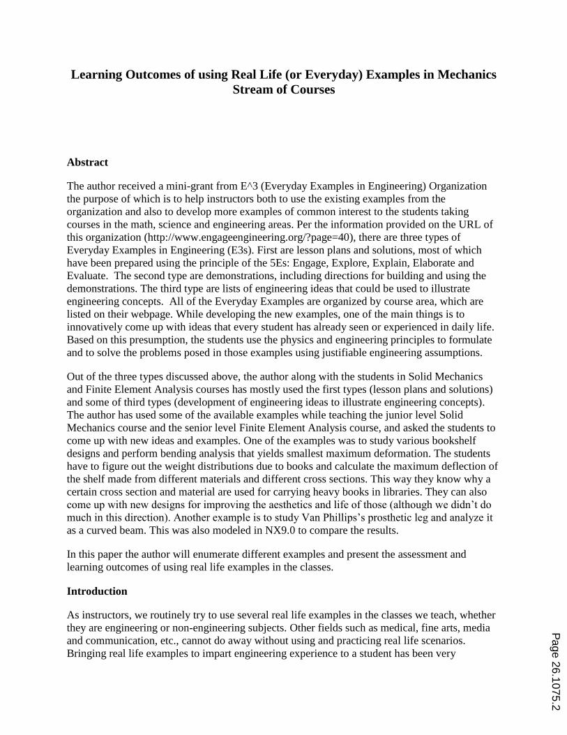
The students visited the library and other places on campus and took photographs of
various bookshelves. They used measurement devices to obtain the geometric dimensions
and weight of the books, as well as, the bookshelves. They submitted a report containing
detailed calculations and the photographs. Figure 1 shows few pictures of the shelf with the
measurement equipment used, and Figure 2 shows the model of the beam that the students
used showing the distributed load due to books. It is curious to observe how thick and
heavy some books can be for the students to carry in their backpack every day. Figure 3
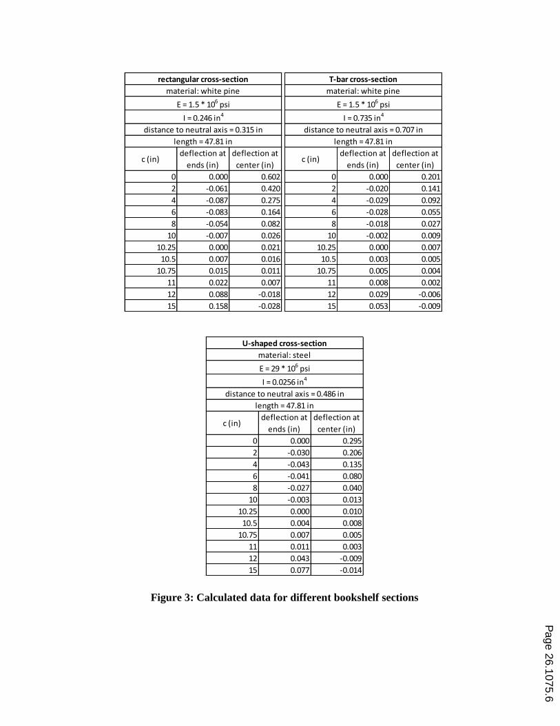
shows typical data and calculations carried out for these.
Page 26.1075.4
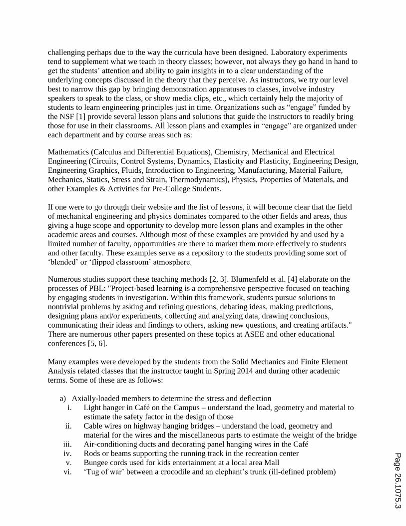
Modeling and Calculations
As mentioned before, the book shelf is modeled as a double overhang beam with non-
uniform distributed load. This is shown in Figure 2. Total weight of the books was obtained
by measurements using a bathroom balance. Linear dimensions were obtained by a ruler and
Vernier calipers.
Calculations
Tabular data in Figure 3 shows calculations of deflections at two critical locations of the
beam as a function of the overhang amount. The last column is actually for a horizontal
channel section. Standard beam deflection tables and excel math program have been used in
arriving at this data. Hand calculations were also expected to validate some of the results.
Figure 1: Book width=6.25 inch; weight=20.4 lbf; shelf=(47.81 x 11.82 x 0.63)
inch
Figure 2: Distributed beam model of each book shelf
Page 26.1075.5
c (in)deflection at
ends (in)
deflection at
center (in)c (in)
deflection at
ends (in)
deflection at
center (in)c (in)
deflection at
ends (in)
deflection at
center (in)
0 0.000 0.602 0 0.000 0.201 0 0.000 0.295
2 -0.061 0.420 2 -0.020 0.141 2 -0.030 0.206
4 -0.087 0.275 4 -0.029 0.092 4 -0.043 0.135
6 -0.083 0.164 6 -0.028 0.055 6 -0.041 0.080
8 -0.054 0.082 8 -0.018 0.027 8 -0.027 0.040
10 -0.007 0.026 10 -0.002 0.009 10 -0.003 0.013
10.25 0.000 0.021 10.25 0.000 0.007 10.25 0.000 0.010
10.5 0.007 0.016 10.5 0.003 0.005 10.5 0.004 0.008
10.75 0.015 0.011 10.75 0.005 0.004 10.75 0.007 0.005
11 0.022 0.007 11 0.008 0.002 11 0.011 0.003
12 0.088 -0.018 12 0.029 -0.006 12 0.043 -0.009
15 0.158 -0.028 15 0.053 -0.009 15 0.077 -0.014
length = 47.81 in
distance to neutral axis = 0.315 in
I = 0.246 in4
E = 1.5 * 106 psi
length = 47.81 in
distance to neutral axis = 0.486 in
I = 0.0256 in4
E = 29 * 106 psi
length = 47.81 in
E = 1.5 * 106 psi
I = 0.735 in4
distance to neutral axis = 0.707 in
material: white pine material: white pine material: steel
rectangular cross-section U-shaped cross-sectionT-bar cross-section
Figure 3: Calculated data for different bookshelf sections
Page 26.1075.6
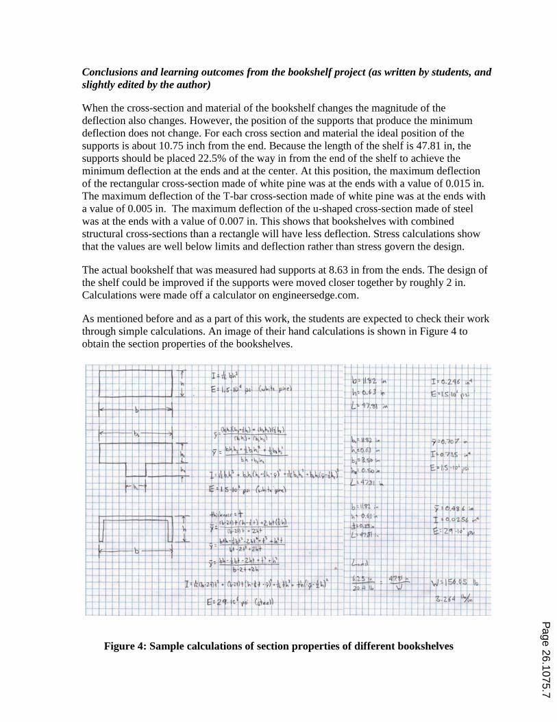
Conclusions and learning outcomes from the bookshelf project (as written by students, and
slightly edited by the author)
When the cross-section and material of the bookshelf changes the magnitude of the
deflection also changes. However, the position of the supports that produce the minimum
deflection does not change. For each cross section and material the ideal position of the
supports is about 10.75 inch from the end. Because the length of the shelf is 47.81 in, the
supports should be placed 22.5% of the way in from the end of the shelf to achieve the
minimum deflection at the ends and at the center. At this position, the maximum deflection
of the rectangular cross-section made of white pine was at the ends with a value of 0.015 in.
The maximum deflection of the T-bar cross-section made of white pine was at the ends with
a value of 0.005 in. The maximum deflection of the u-shaped cross-section made of steel
was at the ends with a value of 0.007 in. This shows that bookshelves with combined
structural cross-sections than a rectangle will have less deflection. Stress calculations show
that the values are well below limits and deflection rather than stress govern the design.
The actual bookshelf that was measured had supports at 8.63 in from the ends. The design of
the shelf could be improved if the supports were moved closer together by roughly 2 in.
Calculations were made off a calculator on engineersedge.com.
As mentioned before and as a part of this work, the students are expected to check their work
through simple calculations. An image of their hand calculations is shown in Figure 4 to
obtain the section properties of the bookshelves.
Figure 4: Sample calculations of section properties of different bookshelves
Page 26.1075.7
Other observations and example titles of other mini-projects
Other examples involving axial loading (cable wires of a bridge, etc., as given previously),
torsion loaded members (twist drill, etc.), and combined bending and torsion (pencil sharpener,
etc.) proved rich source for the solid mechanics and the machine design students to think,
conduct group discussions, make justifiable engineering assumptions, think-pair-share,
modeling, carry out analysis, and validate using simple hand calculations. Some students used
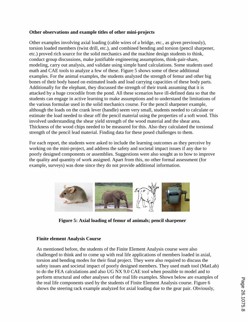
math and CAE tools to analyze a few of these. Figure 5 shows some of these additional
examples. For the animal examples, the students analyzed the strength of femur and other big
bones of their body based on estimated loads and load carrying capacities of these body parts.
Additionally for the elephant, they discussed the strength of their trunk assuming that it is
attacked by a huge crocodile from the pond. All these scenarios have ill-defined data so that the
students can engage in active learning to make assumptions and to understand the limitations of
the various formulae used in the solid mechanics course. For the pencil sharpener example,
although the loads on the crank lever (handle) seem very small, students needed to calculate or
estimate the load needed to shear off the pencil material using the properties of a soft wood. This
involved understanding the shear yield strength of the wood material and the shear area.
Thickness of the wood chips needed to be measured for this. Also they calculated the torsional
strength of the pencil lead material. Finding data for these posed challenges to them.
For each report, the students were asked to include the learning outcomes as they perceive by
working on the mini-project, and address the safety and societal impact issues if any due to
poorly designed components or assemblies. Suggestions were also sought as to how to improve
the quality and quantity of work assigned. Apart from this, no other formal assessment (for
example, surveys) was done since they do not provide additional information.
Finite element Analysis Course
As mentioned before, the students of the Finite Element Analysis course were also
challenged to think and to come up with real life applications of members loaded in axial,
torsion and bending modes for their final project. They were also required to discuss the
safety issues and societal impact of poorly designed members. They used math tool (MatLab)
to do the FEA calculations and also UG NX 9.0 CAE tool when possible to model and to
perform structural and other analyses of the real life examples. Shown below are examples of
the real life components used by the students of Finite Element Analysis course. Figure 6
shows the steering rack example analyzed for axial loading due to the gear pair. Obviously,
Figure 5: Axial loading of femur of animals; pencil sharpener
Page 26.1075.8
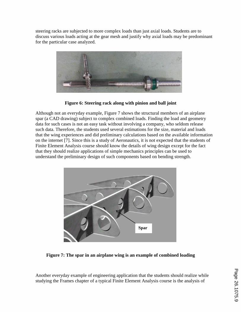
steering racks are subjected to more complex loads than just axial loads. Students are to
discuss various loads acting at the gear mesh and justify why axial loads may be predominant
for the particular case analyzed.
Figure 6: Steering rack along with pinion and ball joint
Although not an everyday example, Figure 7 shows the structural members of an airplane
spar (a CAD drawing) subject to complex combined loads. Finding the load and geometry
data for such cases is not an easy task without involving a company, who seldom release
such data. Therefore, the students used several estimations for the size, material and loads
that the wing experiences and did preliminary calculations based on the available information
on the internet [7]. Since this is a study of Aeronautics, it is not expected that the students of
Finite Element Analysis course should know the details of wing design except for the fact
that they should realize applications of simple mechanics principles can be used to
understand the preliminary design of such components based on bending strength.
Figure 7: The spar in an airplane wing is an example of combined loading
Another everyday example of engineering application that the students should realize while
studying the Frames chapter of a typical Finite Element Analysis course is the analysis of
Spar
Page 26.1075.9
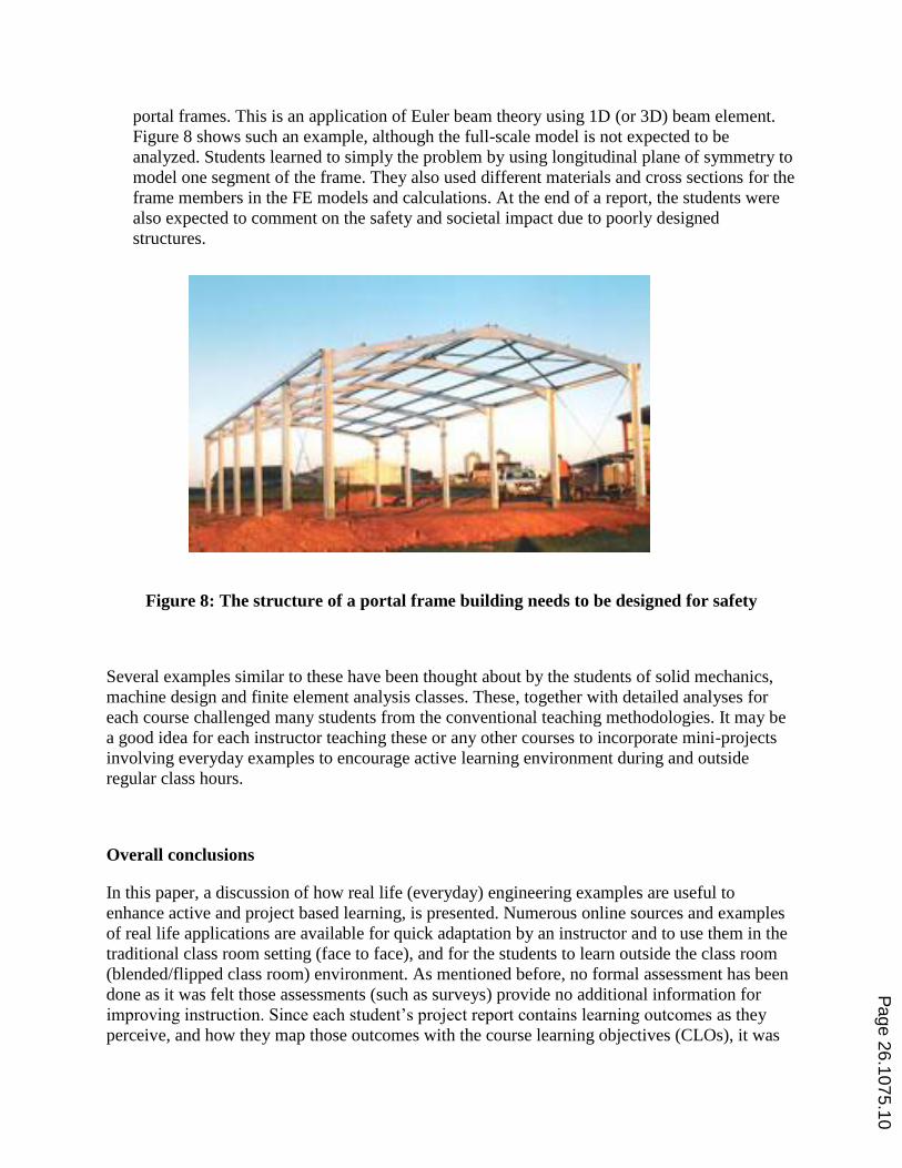
portal frames. This is an application of Euler beam theory using 1D (or 3D) beam element.
Figure 8 shows such an example, although the full-scale model is not expected to be
analyzed. Students learned to simply the problem by using longitudinal plane of symmetry to
model one segment of the frame. They also used different materials and cross sections for the
frame members in the FE models and calculations. At the end of a report, the students were
also expected to comment on the safety and societal impact due to poorly designed
structures.
Figure 8: The structure of a portal frame building needs to be designed for safety
Several examples similar to these have been thought about by the students of solid mechanics,
machine design and finite element analysis classes. These, together with detailed analyses for
each course challenged many students from the conventional teaching methodologies. It may be
a good idea for each instructor teaching these or any other courses to incorporate mini-projects
involving everyday examples to encourage active learning environment during and outside
regular class hours.
Overall conclusions
In this paper, a discussion of how real life (everyday) engineering examples are useful to
enhance active and project based learning, is presented. Numerous online sources and examples
of real life applications are available for quick adaptation by an instructor and to use them in the
traditional class room setting (face to face), and for the students to learn outside the class room
(blended/flipped class room) environment. As mentioned before, no formal assessment has been
done as it was felt those assessments (such as surveys) provide no additional information for
improving instruction. Since each student‟s project report contains learning outcomes as they
perceive, and how they map those outcomes with the course learning objectives (CLOs), it was
Page 26.1075.10
felt that sufficient feedback is available from each report. Moreover, each report contains an
attempt to identify the real life applications, safety and societal impacts of poorly designed
members. Information such as this provides the instructor some confidence that most of what has
been taught is presumably realized by the students.
The general feedback from the students of solid mechanics and other courses taught by the
author, and the overall learning outcomes by assigning the mini-projects was generally positive;
however, some of the group members felt that it was a lot of work while others felt that the
project problems were not well-defined. Ill-defined problems such as a few of these with
ambiguous specifications and requirements are a necessary ingredient of creativity and
innovation. Due to their heavy workload and perhaps non-uniformity of exposure in other classes
of discussing „everyday examples‟, few students seem to be not convinced that assigning mini-
projects is a good idea. As per their overall performance in the classes, it has been consistently
very good with an additional value added to their learning experiences for analyzing real life
everyday examples.
In spite of the above arguments, a more formal assessment and learning outcomes of including
the real life examples needs to be undertaken; however, the feedback shows that many students
appreciated the idea of generating such examples which encouraged them to think critically after
going through and understanding the already developed lesson plans and their solution
procedures. The inherent ambiguity in the data collection to formulate and to solve the problem
proved to be rewarding by way of an appreciation for making justifiable engineering
assumptions. In the meanwhile, all the examples developed by the students will be shared with
interested faculty teaching these classes so that in turn, they too can develop few more examples
for reference by the teaching community.
Acknowledgements
The author wish to sincerely acknowledge the mini-grant support and help provided by Stevens
Institute of Technology, New Jersey (E^3 Examples). Acknowledgements are also due to
students from Kettering University for fabricating several table top models for demonstration in
class rooms. Finally, the author wishes to acknowledge the Indian Institute of Technology,
Gandhinagar, Ahmedabad, India for the sabbatical appointment they gave me during which time
several drafts of this paper have been prepared.
References
1. “engage – Engaging Students in Engineering” funded by the National Science Foundation available at:
http://www.engageengineering.org/?page=40
2. http://en.wikipedia.org/wiki/Active_learning
3. http://en.wikipedia.org/wiki/Project-based_learning
4. Blumenfeld et al (1991): "Motivating Project-Based Learning: Sustaining the Doing, Supporting the
Learning", Educational Psychologist, 26(3&4) 369-398.
5. Greeno, J. G. (2006): “Learning in activity”, R. K. Sawyer (Ed.), The Cambridge handbook of the learning
sciences (pp. 79-96). New York: Cambridge University Press.
Page 26.1075.11
6. Tinker, D., Choate, R., and Lenoir, J. (2014): “Project-Based Learning: The Evolution of a Senior Project
to a Laboratory Test Bed”, ASEE Southeast Section Conference.
7. http://en.wikipedia.org/wiki/Spar_%28aeronautics%29
Page 26.1075.12