learning human welder movement in pipe gtaw: a … · robotic welding is often preferred for its...
TRANSCRIPT

WELDING RESEARCH
WELDING JOURNAL / OCTOBER 2014 , VOL. 93388-s
Introduction Gas tungsten arc welding (GTAW)(Ref. 1) is the primary process used forprecise joining of metals. The GTAWprocess is illustrated in Fig. 1. An arc isestablished between the nonconsum-able tungsten electrode and the basemetal. The base metal is melted by thearc forming a liquid weld pool thatjoins the two pieces of base metal to-gether after solidification. Manual
GTAW is commonly used in industry,especially for applications where feed-back from the process may help tomaintain weld quality and overcomepossible process variations. In thisprocess, skilled welders can oftenmake adjustments based on their observation of the liquid weld poolsurface. Those real-time adjustments oftenlead to desired weld bead geometrycharacterized by backside bead width
wb and positive reinforcement hb —Fig. 2. Welding robots are preferred inmany applications since they outper-form human welders whose perform-ance degrades because of their physi-cal limitations (inconsistent concen-tration, fatigue, stress, and long-termhealth issues). Unfortunately, currentindustrial welding robots are basicallyarticulated arms with a prepro-grammed set of movements, and theylack the intelligence skilled humanwelders possess. They require preci-sion prepared workpieces with littlevariation in geometry and materialproperties. Therefore, their applica-tions are mostly limited to assemblylines for mass-produced products,such as automobiles, where workpiecepreparation is controllable at reason-able costs. However, as outlined in the nation-al robotic report (Ref. 2), the trend inmanufacturing is to produce cus-tomized products in small batcheswhere ideal automated productionlines are not cost effective. As such,welding robots that possess intelli-gence comparable to skilled weldersbut with fewer physical restrictionsand that can work in harsh environ-ments will be one of the keys to main-taining a competitive manufacturingindustry despite relatively high laborcosts/wages. The resultant intelligentwelding robots may also help resolvethe skilled welder shortage issue themanufacturing industry is currentlyfacing. In this research, a novel human-
Learning Human Welder Movement in Pipe GTAW:A Virtualized Welding Approach
A human welder’s speed adjustment under different welding currents was established through virtualized welding
BY Y. K. LIU, Z. SHAO, AND Y. M. ZHANG
ABSTRACT Robotic welding is often preferred for its outperformance over human welders whoare subject to physical limitations to maintain the needed consistency. Unfortunately, industrial welding robots are basically articulated arms with a preprogrammed set ofmovements, lacking the intelligence skilled human welders possess. This paper aims topresent a virtualized welding system that enables learning from human welderintelligence for transferring into a welding robot. In particular, a 6DOF UR5 industrialrobot arm equipped with sensors observed the welding process and performed actualwelding. A human welder operated a virtualized welding torch to adjust the weldingspeed based on the visual feedback from the sensors, and the motion of the virtualizedtorch was recorded and tracked by the robot arm. Nine such teleoperated welding experiments were conducted on pipe using gas tungsten arc welding (GTAW) under differentwelding currents to correlate the welding speed to the welding current. Robotic weldingexperiments, with the robot travel speed determined per the given welding current fromthe resultant correlation, verified that for top part of the pipe between 11 and 1 o’clock,adjusting the welding speed per the current used is adequate to generate acceptablewelds. The obtained correlation between the welding speed and welding current couldbe used in humanmachine cooperative control. It may also provide a constraint for automated welding process control. A foundation is thus established to utilize human intelligence and transfer it to welding robots.
KEYWORDS • Virtualized Welding • Welding Robots • Gas Tungsten Arc Welding (GTAW) • Pipe Welding
Y. K. LIU and Y. M. ZHANG ([email protected]) are with the Institute for Sustainable Manufacturing and Department of Electrical and Computer Engineering, University of Kentucky, Lexington, Ky. Z. SHAO is with Adaptive Intelligent Systems LLC, Lexington, Ky.
Liu et al Supp Oct 2014 WJ_Layout 1 9/12/14 11:31 AM Page 388

WELDING RESEARCH
OCTOBER 2014 / WELDING JOURNAL389-s
machine cooperative welding para-digm, virtualized welding (Ref. 3), isutilized to transfer human intelligenceto welding robots. In this framework,a welding robot working in the actualwelding environment was augmentedwith sensors to observe the workpieceand reconstruct the 3D weld pool sur-face. The obtained data from the sen-sors as feedback from an actual weld-ing process is viewed by a humanwelder in a virtualized welding envi-ronment, and the welder adjusts thewelding parameters accordingly. Thedata and adjustments would also berecorded/analyzed to model how thewelder responded to the 3D weld poolsurface, which is believed to be themajor source of feedback informationa welder may acquire during the weld-ing process, to enable transformationof human intelligence to the weldingrobot to form autonomous intelligentwelding robots. This research serves asthe first study in modeling and analyz-ing human adjustment using the pro-posed virtualized welding platform. Major welding parameters in manu-al GTAW include welding current,welding speed, torch orientation, andarc length. In a particular automatedcontrol system, however, only a fewselected parameters should be adjust-ed to compensate against the effectsfrom possible variations in theprocess. Among all the major weldingparameters, an increase in the weldingcurrent and a decrease in the weldingspeed will significantly increase theheat input into the welding process,
thus consider-ably influencingthe weld poolsurface geome-try. In the au-thors’ previousstudies (Refs.4–6), weldingcurrent was uti-lized to controlthe weldingprocess. Howev-er, in many pipewelding applica-tions, the pipe isoften fixed and cannot be rotated dur-ing welding (e.g., 5G fixed position,that is, the axis of the pipes is horizon-tal; the pipe stays stationary duringwelding; and the welding torch will bemoving along the weld joint (Ref. 7). Normally, welders choose a prede-fined welding current and move thetorch along the pipe since the move-ment of the torch can be convenientlyadjusted by a human welder to over-come the effects from variations. Inthis study, a welder’s movement alongthe welding direction was studied. Al-though other welding parameters(such as torch orientation and arclength) can certainly have an impacton the welding process, for the toppart of the pipe, controlling the weld-ing speed, as confirmed by experi-ments, is sufficient to generate satis-factory welds. The learned correlation betweenthe welding current and welder’s cor-responding movement (i.e., the weld-
ing speed) can be used for human-machine cooperative controlled pipewelding applications where an un-skilled human welder operates a virtu-alized welding torch determining thewelding speed while the welding ma-chine could compensate for his/her in-correct movement by adjusting thewelding current. For automated weld-ing machines that need to simultane-ously control the frontside weld poolcharacteristic parameters and backsideweld penetration by adjusting weldingcurrent and speed, the proposed corre-lation could also provide aninterval/constraint for welding processinput parameters, which will then beutilized to calculate the optimizedwelding current and speed. The remainder of the paper is or-ganized as follows: In the next section,related work is detailed. In the thirdsection, an overview of the virtualwelding system is provided. In thefourth section, experimentation is de-tailed and data from nine teleoperated
Fig. 1 — Illustration of GTAW.
Fig. 2 — Weld pool and complete joint penetration.
Fig. 3 — General view of the virtualized welding system. It consists of a real welding workstation and virtual welding workstation. Data communication between these two workstations isthrough Ethernet.
Liu et al Supp Oct 2014 WJ_Layout 1 9/12/14 11:32 AM Page 389
WELDING RESEARCH
welding experiments are presented/analyzed. A linear correlation wasfound between welding current andspeed. Automated welding experi-ments were conducted under differentwelding currents, in which the pro-posed correlation was utilized to calcu-late the welding speed needed for eachwelding current. Experimental resultsare presented in the fifth section, fol-lowed by conclusions.
Related Work Welding process sensing and con-trol are fundamental problems in au-
tomated welding.While the back-side bead width(illustrated in Fig.2) that quantifiesthe weld jointpenetration is di-rectly observablefrom the backsideof the workpiece,topside sensorsthat may be con-veniently at-tached to thewelding torch arepreferred. Vari-ous topside sen-sors have beenproposed basedon pool oscilla-tion (Ref. 8), ul-trasonic (Ref. 9),infrared (Refs.10, 11), radi-
ographic (Ref. 12), and other methods.The vision-based sensing method,however, is more direct and promi-nent. The weld pool geometry is be-lieved to provide valuable insights intothe state of the welding process. Several 3D weld pool measurementmethods have been proposed, includ-ing model-based reconstruction (Ref.13), stereo-vision measurement (Refs.14, 15), shape from shading (Refs. 16,17), and structured light-based sens-ing (Refs. 18, 19). Depending on thesensing method used, the weldingprocess control systems can also becategorized into pool oscillation-based
control (Ref. 20), radiography-basedcontrol (Ref. 21), thermal-based con-trol (Refs. 22, 23), and vision-basedcontrol (Refs. 24–31). Among all the above control meth-ods, the vision-based control methodis more direct as an emulation of theestimation and decision-makingprocess of a human welder. Zhang(Refs. 25, 26) proposed an adaptivepredictive and neuro-fuzzy model-based control algorithm to control thefrontside weld pool width and back-side bead width. Chen (Refs. 27, 28)proposed a self-learning fuzzy neuralnetwork controller to simultaneouslycontrol the weld pool length andwidth. Tsai (Ref. 29) proposed an au-tomatic pulsed GTA pipe welding sys-tem with fuzzy control technique tocontrol the width of the pool. Liu andZhang (Refs. 30, 31) controlled theweld pool geometry and weld penetra-tion using a recently developed 3Dweld pool sensing method detailed in(Ref. 19). Human welder intelligence-basedmodeling and control provides an al-ternative route to develop weldingprocess control algorithms. Conven-tional welding process control meth-ods (Refs. 20–31) typically involve twosteps: modeling of the welding processand design of the control algorithm.As an alternative method in this pa-per, the design of the control algo-rithm becomes a one-step process —modeling a human welder’s responseas a function of feedback from the sen-sor. The design becomes simpler and
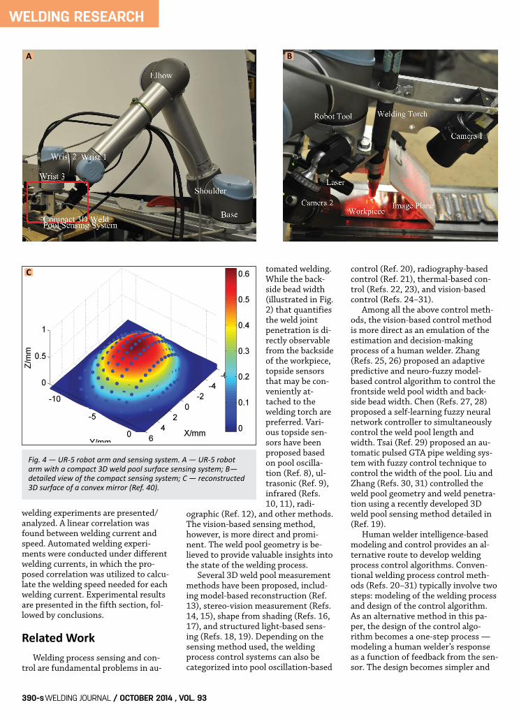
Fig. 4 — UR5 robot arm and sensing system. A — UR5 robotarm with a compact 3D weld pool surface sensing system; B—detailed view of the compact sensing system; C — reconstructed3D surface of a convex mirror (Ref. 40).
A B
C
WELDING JOURNAL / OCTOBER 2014 , VOL. 93390-s
Liu et al Supp Oct 2014 WJ_Layout 1 9/12/14 11:33 AM Page 390

WELDING RESEARCH
less designer dependent. In addition,human responses are considered reli-able and robust for applications wherehuman welders are currently relied onbefore other effective methods are ad-equately developed. Learning a humanwelder’s response would provide a con-venient method to take advantage ofvaluable human welder experience andprovide the foundation to exceed a hu-man welder’s physical limitations(Refs. 4–6). Welder training systems have beeninvestigated in the manufacturing in-dustry to accelerate the learning
process and compen-sate for the shortageof a welding instruc-tor (e.g., EWI Ad-vanceTrainerTM (Ref.32) and RealWeldTrainerTM (Ref. 33)).Recently, virtual re-ality (VR) has beenrecognized for itsvalue in weldertraining (Ref. 34).Some sophisticatedsystems for trainingwith a head-mount-ed display (HMD)have been proposedrecently, such asARC+ (Ref. 35), theFronius virtual weld-ing system (Ref. 36),and VRTEX 360°
(Ref. 37). However,these systems do not employ a see-through method; instead, they applyfully simulated environment on thedisplay. Among these VR methods, VRTEX360 is considered one of the most so-phisticated welder training systems. Amock-up welding torch is equippedwith sensors so that it can be fullytracked. A welder’s helmet is fittedwith HMD to provide simulated im-ages. As a training tool, the imagesshown to the trainee are entirely simu-lated. While this may be adequate for
the purpose of training, it is unlikelyto be able to simulate the complexityand possible variations in a real weld-ing environment. Another drawback isthat the focus distance is fixed in mostdisplay types, resulting in poor eye ac-commodation. In this study, we chose to use aug-mented reality (AR) techniques (Refs.38, 39) for the visualization aspect ofvirtualized welding. This AR allows auser to see the real world with virtualobjects superimposed upon or com-posited with the real world. AlthoughAR has been used in many applicationareas including education, health care,military, and entertainment, its appli-cation in welding and welder intelli-gence learning has not yet been reported.
Virtualized WeldingSystem Overview
The virtualized welding system uti-lized in this study (shown in Fig. 3)consists of two workstations — awelding station and virtual station. Inthe virtual station, a human weldercan view the mockup where the weldpool images (from direct viewing oreye view camera) is rendered and dis-played, and moves the virtual weldingtorch accordingly as if he/she is rightin front of the workpiece. The humanwelder movement is accurately cap-
Fig. 5 — A — Detailed view of the virtual station. Major components include a Leap motion tracking sensor, mockup pipe,computer screen, highresolution camera, and projector; B —virtual welding torch.
Fig. 6 — Visualization of the pipe. A — Eye view of the workpiece;B — virtual view of the mockup. The image from the eye viewcamera has been visualized on the mockup. C — Closeup view; D— the mockup at different points of view.
A A
B
B
DC
OCTOBER 2014 / WELDING JOURNAL 391-s
Liu et al Supp Oct 2014 WJ_Layout 1 9/12/14 11:33 AM Page 391

WELDING RESEARCH
WELDING JOURNAL / OCTOBER 2014, VOL. 93392-s
tured by a Leap motion sensor, andthe obtained 3D virtual welding torchtip coordinates will be sent to the PC.The robot arm equipped with thewelding torch receives commands viaEthernet from the PC including thenext pose (robot tool 3D position andorientation) and robot tool movementspeed. It then executes the commandand sends the current robot tool posi-tion back to the PC.
Welding Station
The welding station consists of anindustrial welding robot, eye viewcamera, and a compact 3D weld poolsurface sensing system (Ref. 40). Therobot utilized in this study (depictedin Fig. 4A) is a Universal Robot, UR-5,with six degrees of freedom (DOF).The UR-5 industrial robot is a six-jointed robot arm with a low weight of18 kilos, lifting ability of 5 kilos, andworking radius of 85 cm, respectively.The repeatability of the robot is ±0.1mm. The robot is connected to a con-troller, which is used to control themotions of the robot. There is a touch
pad user interface that allows the userto program, control, and move the ro-bot. The robot can also be pro-grammed using URScript, a script lan-guage developed by the robot manu-facturer. The robot (client) and PC(server) is communicated via Ethernetusing TCP/IP protocol and socket pro-gramming. Figure 4B shows the developedcompact 3D weld pool surface sensingsystem for our robotic welding system(Ref. 40). In this system, a low-powerlaser (19 by 19 structure light pattern)is projected to the weld pool surface,and its reflection from the specularweld pool surface is intercepted andimaged by a CCD camera (camera 1 inFig. 4B). It is known that arc light is anomnidirectional light source. Its inten-sity decreases quadratically with thedistance traveled, but the laser, due toits coherent nature, does not signifi-cantly lose its intensity. Hence, it ispossible to intercept the reflection ofthe illumination laser from the weldpool surface with an imaging planeplaced at an appropriate distance fromthe arc.
From the distorted reflection pat-tern on the imaging plane and the as-sumption of a smooth weld pool sur-face, the 3D shape of the weld poolsurface can be obtained. By using aspecific image processing and recon-struction algorithm (Ref. 19), a 3Dspecular weld pool can be reconstruct-ed in real time. This 3D weld poolgeometry information will be utilizedto correlate the welder’s movementand the 3D weld pool geometry to en-able the adaptive and accurate controlof the welding process. To verify theeffectiveness and accuracy of the com-pact 3D weld pool surface sensing sys-tem, a spherical convex mirror withknown geometry (Edmund OpticsNT64-057) is used as a benchmark(Ref. 40). The reconstructed 3D weldpool surface is depicted in Fig. 4C. It isobserved that most of the height er-rors are within 0.06 mm, especially inthe central range of the weld pool.
Virtual Station
The visualization system employs acomputer screen for displaying therendered visual information from theeye view camera over the flat work-piece — Fig. 5. If the workpiece is a3D-shaped object (e.g., pipe), the visu-alization system employs a mockuppipe with the same dimensions as anactual pipe and projects renderedvideo on its surface. The 3D scanningsystem consists of a high-resolutioncamera and projector. By utilizing thestructured light scan algorithm (Ref.41) with subpixel refinement (Ref. 42)for reconstructing the geometry of a3D object, this system can provide ahigh accuracy point cloud and mesh ofthe mockup. In the authors’ previous paper (Ref.40), virtual welding for a flat work-piece has been discussed. In this study,a pipe welding application with 3D vi-sualization is examined. Figure 5Bshows the virtual welding torch. Figure 6 shows the visualization of
Fig. 7 — A–C — Sample images from camera 2 (eye view) with welding currents 45, 50,and 55 A, respectively. D–F — Corresponding images from camera 1 (structured lightlaser dots that will then be used for 3D weld pool reconstruction) corresponding to A–C.
Table 1 — Welding Parameters
Current(A) Welding Arc Length Argon Speed mm Flow Rate (mm/s) (L/min)
45, 50, 55 — 4 11.8
A B C
D E F
Liu et al Supp Oct 2014 WJ_Layout 1 9/12/14 11:34 AM Page 392
WELDING RESEARCH
OCTOBER 2014 / WELDING JOURNAL393-s
the pipe. Both the eye view of theworkpiece (Fig. 6A) and virtual view ofthe mockup (together with the visual-ized eye view image) are presented. Itwill be shown that the proposed sys-tem is able to conduct virtual weldingexperiments whose data will then berecorded and utilized to form a welderresponse model.
Experimentation
Nine teleoperated experiments areconducted in this section, and the ex-perimental results are presented plusanalyzed.
Experiment
Stainless steel pipe was welded us-ing the direct current electrode nega-tive GTAW process. The material ofthe pipe was stainless steel 304. Theouter diameter and wall thickness ofthe pipe were 113.5 and 2.03 mm, re-spectively. The welding parameters areillustrated in Table 1. The welding cur-rent was selected as one of the threetypical values representing small,medium, and large welding current(45, 50, and 55 A). The arc length wasmaintained at 4 mm. The humanwelder observes the virtualized weldpool rendered on the mockup pipe and controls the virtual welding torchmovement (i.e., welding speed) accordingly.
Figure 7 de-picts sample im-ages captured inthese welding ex-periments withthe welding cur-rent being 45, 50,and 55 A, respec-tively. Figure 7A–Care the imagescaptured by cam-era 2 (i.e., eyeview). As can beobserved, different welding currentsand welding speeds generate differentweld pool shapes. The welder can ob-serve the weld pool and move the vir-tual welding torch accordingly basedon this visual feedback. It is noted thatimages from the eye view camera areonly for a human welder to view andcontrol the welding process. For an au-tomated welding task, however, eyeview images can only be used to get 2Dinformation from the weld pool (weldpool width and length). 3D weld poolgeometry is relatively difficult to beextracted from these images. Instead,images from camera 1 (in Fig. 4B) willbe utilized to reconstruct 3D weld poolshape using a specific image process-ing and reconstruction algorithm (Ref. 19). Figure 7D–F are the images fromcamera 1 (structured light laser reflec-tion dots). It is observed that differentweld pool shapes (shown in Fig. 7A–C)
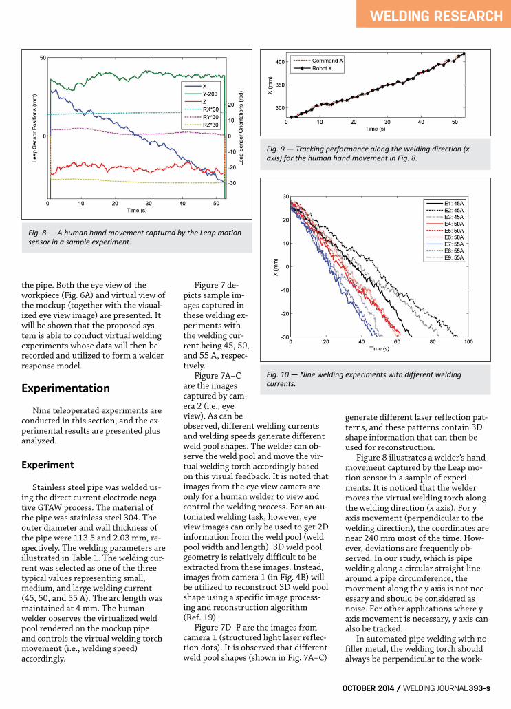
generate different laser reflection pat-terns, and these patterns contain 3Dshape information that can then beused for reconstruction. Figure 8 illustrates a welder’s handmovement captured by the Leap mo-tion sensor in a sample of experi-ments. It is noticed that the weldermoves the virtual welding torch alongthe welding direction (x axis). For yaxis movement (perpendicular to thewelding direction), the coordinates arenear 240 mm most of the time. How-ever, deviations are frequently ob-served. In our study, which is pipewelding along a circular straight linearound a pipe circumference, themovement along the y axis is not nec-essary and should be considered asnoise. For other applications where yaxis movement is necessary, y axis canalso be tracked. In automated pipe welding with nofiller metal, the welding torch shouldalways be perpendicular to the work-
Fig. 8 — A human hand movement captured by the Leap motionsensor in a sample experiment.
Fig. 10 — Nine welding experiments with different welding currents.
Fig. 9 — Tracking performance along the welding direction (xaxis) for the human hand movement in Fig. 8.
Liu et al Supp Oct 2014 WJ_Layout 1 9/12/14 11:34 AM Page 393

WELDING RESEARCH
WELDING JOURNAL / OCTOBER 2014, VOL. 93394-s
piece. Once the x axis movement is ac-curately tracked, the movement alongthe z axis and x, y, z orientations canbe properly determined. It will beshown in the automated welding ex-periment section that satisfactorywelds can be obtained for welding thetop part of the pipe. For full positionpipe welding, however, this is not thecase. In positions other than the toppart of the pipe, a certain angle be-tween the welding torch and pipe sur-face may be required to provide addi-tional control on the arc pressure act-ing on the weld pool against gravita-tional force (Ref. 7). Future study will focus on full posi-tion pipe welding where the torch ori-entation will also be tracked, learned,and adjusted. Figure 9 shows the tracking per-formance in the x direction. It is ob-served that using the proposed predic-tive control algorithm in Ref. 3, the ro-bot can track the human movementwith sufficient accuracy.
Data Processing
Nine teleoperated experimentswere conducted by a human welder. Inexperiments 1–3, the welding currentis set at 45 A. In experiments 4–6, thewelding current was set at 50 A. In ex-periments 7–9, the welding currentwas set at 55 A. Other welding param-eters were the same as those specifiedin Table 1. Figure 10 presents the x position
data in nine experi-ments. Generally,for relatively largerwelding current (55A), the humanwelder moved thetorch at greaterspeeds (or finishedwelding with lesstime, in about 45 to50 s). For mediumwelding current (50A), the humanwelder used medi-um movementspeeds throughoutthe experiments and finished thewelding task in about 60 s. For smallwelding current (45 A), the welderused a lower welding speed and finish-es the welding tasks in about 70 to 90s. It is noticed, however, that speedvariations occurred in these experi-ments for the same welding current.This is understandable because the hu-man welder determines his/her move-ment based on his observation of theweld pool. However, trends in thewelding speed with respect to thewelding current can be easily ob-served. In the next subsection, these datawill be utilized to learn the humanmovement. It is observed in Fig. 10 that a hu-man hand movement contains highfrequency and needs to be filtered be-fore learning. A low-pass filter was de-signed as follows
where Dx,k is x position coordinate be-fore filtering at instant k while Dxf,kand Dxf, k–1 are filtered x position coor-dinates at instant k and k–1, respec-tively. Sxf,k is the filtered speed alongthe x axis, and Ts is the sampling time(0.5 s). α∈ (0,1) is the smoothing co-efficient. As α becomes larger, the po-sition deviates from the actual humanmovement but with better robustnessand smoothness. It is observed that α= 0.9 can achieve a good tradeoff be-tween tracking a human movementand smoothness. Figure 11 shows the filtered posi-tion and speed in experiment 4. It isobserved that the filter is able tosmooth the position and speed signal.
D D D
S D D Txf ,k xf ,k x ,k
xf ,k xf ,k xf ,k s
(1 )
( )/(1)
1
1
= α + −α
= −
⎧⎨⎪
⎩⎪
−
−
Fig. 11 — Comparison between before and after filtering (x position and welding speed) in experiment 4.
Fig. 12 — Normalized power spectrum before and after filtering in nine welding experiments. A — The x position; B — welding speed.
A
B
Liu et al Supp Oct 2014 WJ_Layout 1 9/12/14 11:35 AM Page 394
Large oscillations in the speed are suf-ficiently depressed. To further understand the filter ef-fect, frequency domain analysis is pre-sented. Figure 12 shows the normal-ized power spectrum for the x positionand movement speed in nine experi-ments. For a position signal, the ma-jority of the signal power is centeredbelow 1 Hz (i.e., the majority of theenergy for position response is below
1 Hz). This makessense because thehuman welder ad-justment should beslow given the rela-tively slow GTAWprocess. No notice-able differences areobserved by apply-ing the low-pass filter.
For movementspeed, on the otherhand, the normal-ized signal powerhas been sufficientlysuppressed for fre-quencies larger than0.5 Hz. This is ex-pected because large,high-frequencymovement corre-sponds to thetremor of the hu-man hand andshould be sup-pressed. It is ob-served that the pro-posed filter is able tosuppress the high-
frequency movement that might de-grade the welding performance. Because the smoothness of the hu-man hand movement varies from per-son to person, it is evident that differ-ent welders should have differentsmoothing coefficients. To obtain thesmoothing coefficient for a specificoperator, a training period can be con-ducted and the process described inthis section can be applied accordingly.
Learning Result and Analysis
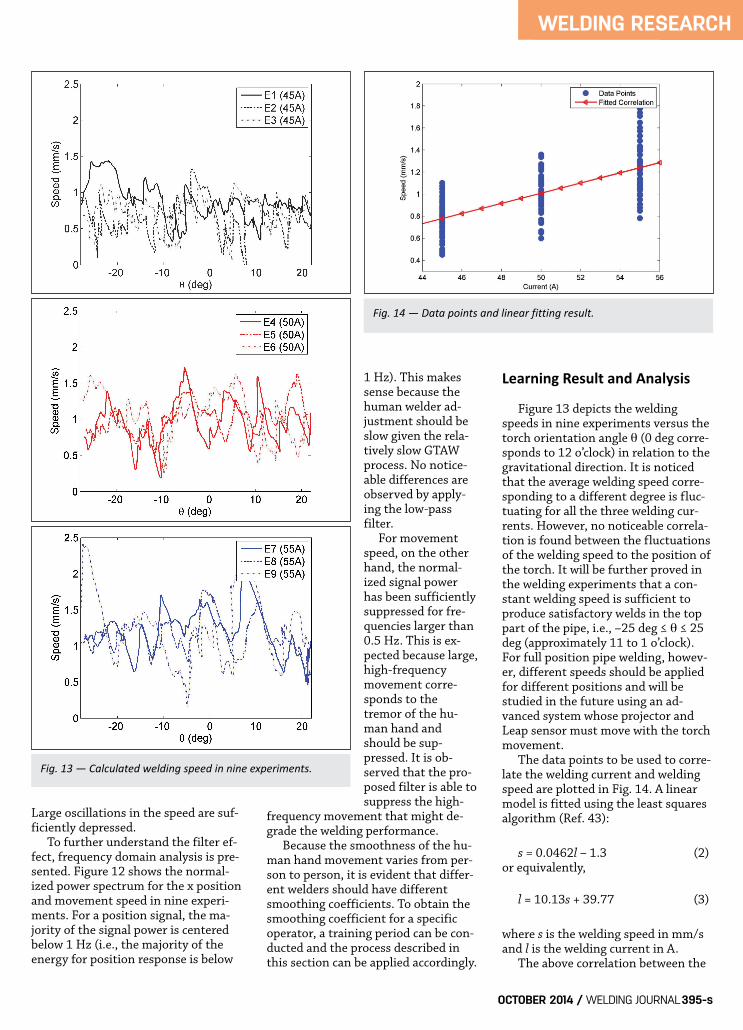
Figure 13 depicts the weldingspeeds in nine experiments versus thetorch orientation angle θ (0 deg corre-sponds to 12 o’clock) in relation to thegravitational direction. It is noticedthat the average welding speed corre-sponding to a different degree is fluc-tuating for all the three welding cur-rents. However, no noticeable correla-tion is found between the fluctuationsof the welding speed to the position ofthe torch. It will be further proved inthe welding experiments that a con-stant welding speed is sufficient toproduce satisfactory welds in the toppart of the pipe, i.e., –25 deg ≤ θ ≤ 25deg (approximately 11 to 1 o’clock).For full position pipe welding, howev-er, different speeds should be appliedfor different positions and will bestudied in the future using an ad-vanced system whose projector andLeap sensor must move with the torchmovement. The data points to be used to corre-late the welding current and weldingspeed are plotted in Fig. 14. A linearmodel is fitted using the least squaresalgorithm (Ref. 43):
s = 0.0462l – 1.3 (2)or equivalently,
l = 10.13s + 39.77 (3)
where s is the welding speed in mm/sand l is the welding current in A. The above correlation between the
WELDING RESEARCH
OCTOBER 2014 / WELDING JOURNAL395-s
Fig. 13 — Calculated welding speed in nine experiments.
Fig. 14 — Data points and linear fitting result.
Liu et al Supp Oct 2014 WJ_Layout 1 9/12/14 11:44 AM Page 395

welding current and welding speed canbe used for human-machine coopera-tive teleoperated pipe welding applica-tions where an unskilled humanwelder operates the torch (determin-ing the actual welding speed) while thewelding machine could compensatehis/her inaccurate movement (inaccu-rate welding speed) by adjusting thewelding current. It could also be used to provide aparameter interval for simultaneouslycontrolling the frontside weld poolsurface characteristic parameters andbackside joint penetration in automat-ed welding. This learned correlation
will then be applied in welding experi-ments to demonstrate the effective-ness of the learned welding speedfrom the human welder.
Automated WeldingExperiment Automated welding experimentsusing learned welding speeds wereconducted, and the experimental re-sults are presented/analyzed. Thewelding parameters are the same asthose listed in Table 1. Three weldingexperiments are conducted with thewelding current set at 45, 50, and 55
A, respectively, and the arc lengthmaintained at 4 mm. It is observedfrom Fig. 15 that by applying thelearned welding speed, satisfactorywelds are obtained. Consistent back-side weld bead widths were obtainedin all three experiments. For a 45-Awelding current, the backside beadwidth was maintained at about 3.5mm for all positions (from –25 to 25deg). Similarly, for welding currents of50 and 55 A, backside bead widthswere properly maintained at about 3.7and 3.6 mm. To further demonstrate the pro-posed model in generating satisfactory
WELDING RESEARCH
WELDING JOURNAL / OCTOBER 2014, VOL. 93396-s
Fig. 15 — Automated welding experiment results using different welding currents. A, D — Front and back view of the welds for weldingcurrent 45 A; B, E — front and back view of the welds for welding current 50 A; C, F — front and back view of the welds for welding current 55 A.
A B
C D
E F
Liu et al Supp Oct 2014 WJ_Layout 1 9/12/14 11:36 AM Page 396

welds under varying welding currents,the welding experiment was conductedby varying the welding current duringan experiment from 48 to 53 A then to45 A, and the welding speed calculatedby Equation 2 is sent to the weldingrobot. An acceptable weld is shown in Fig.16. Specifically, a welding current of48 A was first applied for 20 s — Fig.17. The calculated welding speed was0.918 mm/s and the obtained backsidebead width was about 3.8 mm. Thenthe welding current increased to 55 Aand lasted for 20 s. By increasing thewelding speed to about 1.15 mm/s, anearly consistent backside bead widthwas achieved. Finally, the welding cur-rent was set to 45 A for 20 s and thecalculated welding speed was 0.78mm/s. The backside bead width waswell maintained to about 3.9 mm. It is concluded that by controllingthe welding speed, satisfactory weldscan be achieved, given the other weld-ing parameters are maintained at theirnominal values. If these welding pa-rameters deviate from their nominal
values, controllingthe welding speedmight not be suffi-cient to produce sat-isfactory welds.However, thelearned weldingspeeds for differentwelding currents canprovide an addition-al constraint in de-signing a controllerfor the weldingprocess. The 3D weldpool shape will becorrelated to thewelder’s movement,and an adaptive con-trol scheme will bedeveloped to copewith complex varia-
tions in the process parameters in theauthors’ future research.
Conclusions This research utilized a new humanmachine welding paradigm, virtualizedwelding, to learn a human welder’sspeed adjustment under differentwelding currents. Learning experi-ments through teleoperation wereconducted by a human welder to gen-erate satisfactory welds under differ-ent welding currents. A correlation be-tween the welding current and weldingspeed was proposed for GTAW pipewelding with specified welding condi-tions. Consistent penetration and sat-isfactory welds were generated in au-tomated welding experiments. It isalso observed that for the top part ofthe pipe welding, instead of manipu-lating a full set of welding parameters(including torch orientation and arclength, etc.), adjusting the weldingspeed was sufficient to generate satis-factory welds.
Future work of the authors is tofurther study skilled human welders’intelligence in dynamic welding condi-tions and adaptively control the weld-ing process. Full position pipe weldingwill also be studied where weldingspeed and torch orientation could besimultaneously controlled to generatesatisfactory welds.
This work was funded by the Na-tional Science Foundation under grantIIS-1208420. Y. K. Liu would like tothank M. Khattak and B. Fu at theUniversity of Kentucky for their helpin robot programming and welding ex-periments.
1. O’Brien, R., ed. 1998. Volume 2 – Welding processes. Welding Handbook,8th Edition, American Welding Society,Miami, Fl. 2. A roadmap for US robotics: from in-ternet to robotics. May 2009.http://www.usrobotics.us/reports/ccc%20Re-port.pdf. 3. Liu, Y. K., Zhang, Y. M., Fu, B., andYang, R. G. Nov. 10–13, 2013. Predictivecontrol for robot arm teleoperation. Proc.39th Annual Conference of IEEE IndustrialElectronics Society (IECON13). Vienna, Aus-tria. 4. Liu, Y. K., Zhang, W. J., and Zhang, Y.M. Dynamic neuro-fuzzy based human in-telligence modeling and control in GTAW.IEEE Transactions on Automation Scienceand Engineering (in press). DOI:10.1109/TASE.2013.2279157. 5. Liu, Y. K., Zhang, Y. M., and Kvidahl,L. 2014. Skilled human welder intelligencemodeling and control: Part 1 – Modeling.Welding Journal 93(2): 46-s to 52-s. 6. Liu, Y. K., Zhang, Y. M., and Kvidahl,
WELDING RESEARCH
OCTOBER 2014 / WELDING JOURNAL 397-s
Fig. 16 — Automated welding experiment results using varying welding currents from 48 to 53 to 45 A. A — Front view of weld; B — backview of weld.
Fig. 17 — Welding current and speed in Fig. 16.
A B
References
Acknowledgments
Liu et al Supp Oct 2014 WJ_Layout 1 9/12/14 11:37 AM Page 397
L. 2014. Skilled human welder intelligencemodeling and control: Part II – Analysisand control applications. Welding Journal93(5): 162-s to 170-s. 7. Cary, H. B., and Helzer, S. C. 2005.Modern Welding Technology. Pearson/Pren-tice Hall. 8. Renwick, R., and Richardson, R.1983. Experimental investigation of GTAweld pool oscillations. Welding Journal62(2): 29-s to 35-s. 9. Hardt, D., and Katz, J. 1984. Ultra-sonic measurement of weld penetration.Welding Journal 63(9): 273-s to 281-s. 10. Nagarajan, S., Banerjee, P., Chen,W., and Chin, B. 1992. Control of the weld-ing process using infrared sensors. IEEETransactions on Robotics and Automation8(1): 86–93. 11. Ghanty, P., Vasudevan, M., Mukher-jee, D. P., et al. 2008. Artificial neural net-work approach for estimating weld beadwidth and depth of penetration from in-frared thermal image of weld pool. Scienceand Technology of Welding and Joining 13(4):395–401. 12. Rokhlin, S. I., and Guu, A. C. 1990.Computerized radiographic sensing andcontrol of an arc welding process. WeldingJournal 69(3): 83-s to 97-s 13. Zhang, G. J., Yan, Z. H., and Lin, L.2006. Reconstructing a three-dimensionalGMAW-P weld pool shape from a two-di-mensional visual image. Measurement Sci-ence and Technology 17(7): 1877–1882. 14. Steele, J., Mnich, C., Debrunner, C.,Vincent, T., and Liu, S. 2005. Developmentof closed-loop control of robotic weldingprocesses. Industrial Robot: An InternationalJournal 32(4): 35–55. 15. Zhao, C. X., Richardson, I. M., Ken-jeres, S., Kleijn, C. R., and Saldi, Z. 2009. Astereo vision method for tracking particleon the weld pool surface. Journal of AppliedPhysics 105(12): 104–123. 16. Wang, J., Wang, W., and Chen, S.2009. Inspection of welding pool heightfrom shading in pulsed GTAW with wirefiller. Industrial Robot: An InternationalJournal 36(3): 270–276. 17. Li, L. P., Yang, X. Q., Zhang, F. Y.,and Lin, T. 2011. Research on surface re-cover of aluminum alloy GTAW-P poolbased on SFS. Robotic Welding, Intelligenceand Automation, Lecture Notes in ElectricalEngineering 88: 307–314. 18. Song, H. S., and Zhang, Y. M. 2007.Image processing for measurement ofthree-dimensional GTA weld pool surface.Welding Journal 86(10): 323-s to 330-s. 19. Zhang, W. J., Liu, Y. K., and Zhang,Y. M. May 6–9, 2013. Real-time measure-ment of the weld pool surface in GTAWprocess. Proc. 2013 IEEE International In-strumentation and Measurement TechnologyConference (I2MTC 2013), Minneapolis,Minn.
20. Andersen, K., Cook, G. E., Barnett,R. J., et al. 1997. Synchronous weld pooloscillation for monitoring and control.IEEE Transactions on Industry Applications33(2): 464–471. 21. Guu, A. C., and Rokhlin, S. I. 1992.Arc weld process control using radiograph-ic sensing. Materials Evaluation 50(11):1344. 22. Song, J. B., and Hardt, D. E. 1993.Closed-loop control of weld pool depth us-ing a thermally based depth estimator.Welding Journal 72(10): 471-s to 478-s. 23. Wikle III, H. C., Kottilingam, S.,Zee, R. H., and Chin, B. A. 2001. Infraredsensing techniques for penetration depthcontrol of the submerged arc weldingprocess. Journal of Materials ProcessingTechnology 113(1): 228–233. 24. Pietrzak, K. A., and Packer, S. M.1994. Vision-based weld pool width con-trol. Journal of Engineering for Industry-Transactions of ASME 116(1): 86–92. 25. Zhang, Y. M., Kovacevic, R., andWu, L. 1996. Dynamic analysis and identi-fication of gas tungsten arc weldingprocess for weld penetration control. Jour-nal of Engineering for Industry-Transactionsof ASME 118(1): 123–136. 26. Zhang, Y. M., and Kovacevic, R.1998. Neurofuzzy model-based predictivecontrol of weld fusion zone geometry. IEEETransactions on Fuzzy Systems 6(3):389–401. 27. Chen, S. B., Lou, Y. J., Wu, L., et al.2000. Intelligent methodology for sensing,modeling and control of pulsed GTAW:Part I — Bead-on-plate welding. WeldingJournal 79(6): 151-s to 163-s. 28. Chen, H., Lv, F., Lin, T. et al. 2009.Closed-loop control of robotic arc weldingsystem with full-penetration monitoring.Journal of Intelligent and Robotic Systems56(5): 565–578. 29. Tsai, C. H., Hou, K. H., and Chuang,H. T. 2006. Fuzzy control of pulsed GTAwelds by using real-time root bead imagefeedback. Journal of Materials ProcessingTechnology 176(1): 158–167. 30. Liu, Y. K., and Zhang, Y. M. 2013.Control of 3D weld pool surface. ControlEngineering Practice 21(11): 1469–1480. 31. Liu, Y. K., and Zhang, Y. M. 2014.Model-based predictive control of weldpenetration in gas tungsten arc welding.IEEE Transactions on Control Systems Tech-nology 22(3): 955–966. 32. EWI AdvanceTrainer™. 2011.http://www.ewi.org/ewi-advancetrainer%E2%84%A2-innovation-in-welder-training. 33. EWI RealWeld Trainer™. 2013.http://www.realweldsystems.com/tag/ewi/. 34. Fast, K., Gifford, T., and Yancey, R.2004. Virtual training for welding. Proc.3rd IEEE and ACM International Symposiumon Mixed and Augmented Reality: 298–299.
35. Choquet, C. 2008. Arc+: Today’s vir-tual reality solution for welders. Proc. Inter-national Conference of Safety and Reliabilityof Welded Components in Energy and Process-ing Industry. 36. Fronius International, Fronius Vir-tual Welding. 2011.http://www.fronius.com/cps/rde/xchg/SID-A0A61DDC-33C5ACA6/fronius_internation-al/hs.xsl/79_15490_ENG_HTML.htm. 37. The Lincoln Electric Co., VRTEX360—Virtual Reality Arc Welding(VRAW™) training trainer. 2011.http://www.Lincolnelectric.com/en-us/equip-ment/training-equipment/Pages/vrtex360.aspx. 38. Azuma, R. T. 1997. A survey of aug-mented reality. Teleoperators and VirtualEnvironments 6(4): 355–385. 39. van Krevelen, D. W. F., and Poelman,R. 2010. A survey of augmented realitytechnologies, applications and limitations.The International Journal of Virtual Reality9(2): 1–20. 40. Liu, Y. K., and Zhang, Y. M. 2014.Toward intelligent welding robot with hu-man knowledge: A remotely-controlled ap-proach. IEEE Transactions on AutomationScience and Engineering, accepted for publi-cation. 41. Lanman, D., and Taubin, G. 2009.Build your own 3D scanner: Optical trian-gulation for beginners. ACM SIGGRAPHAsia 2009 Courses. 42. Taylor, C. J., 2012. Implementinghigh resolution structured light by exploit-ing projector blur. Proc. 2012 IEEE Work-shop on Applications of Computer Vision(WACV), Breckenridge, Colo. 43. Astrom, K. J., and Wittenmark, B.1995. Adaptive Control. Addison-Wesley.
WELDING RESEARCH
WELDING JOURNAL / OCTOBER 2014, VOL. 93398-s
Change of Address? Moving?
Make sure delivery of your Welding Journal is not interrupted. ContactMaria Trujillo in the MembershipDepartment with your new address in-formation — (800) 443-9353, ext. 204;[email protected].
Liu et al Supp Oct 2014 WJ_Layout 1 9/12/14 11:39 AM Page 398