leaky bloch modal evolution of wideband reflectors with
TRANSCRIPT
Leaky Bloch modal evolution of wideband reflectorswith zero-contrast gratings from symmetric trapezoid
to triangle ridge shapes
Guohua Xing,a,b Shanwen Zhang,a,* and Robert Magnussonc
aChinese Academy of Sciences, Changchun Institute of Optics and Fine Mechanics and Physics,National Engineering Research Center for Diffraction Gratings Manufacturing and
Application, Changchun, Jilin, ChinabUniversity of Chinese Academy of Sciences, Beijing, China
cUniversity of Texas at Arlington, Department of Electrical Engineering, Arlington,Texas, United States
Abstract. We treat wideband subwavelength guided-mode resonant gratings with grating-depthdependent duty cycles. By rigorous numerical computations, we visualize Bloch modal evolu-tion while transforming the grating profile from trapezoid to triangle. Parametric optimization isachieved using the coordinate transformation method of Chandezon. With the increase of theprofile base angle, the higher mixed resonant modes TM1;1&2 attract and combine and interactwith the modes at both sides, forming wide reflection bands. This modal combination and inter-action are the key determinant of broadband reflectivity spectral location and width. The opti-mized structure exhibits 99% reflectivity across a 613-nm spectral range, spanning a 1438- to2051-nm wavelength range with a fractional bandwidth of ∼35%. It is shown that gratings withtrapezoidal profiles possess a good tolerance to groove depth variation, thus being easier to fab-ricate with a diamond-tip than triangular profile-based gratings. © The Authors. Published by SPIEunder a Creative Commons Attribution 4.0 Unported License. Distribution or reproduction of this work inwhole or in part requires full attribution of the original publication, including its DOI. [DOI: 10.1117/1.OE.59.12.127102]
Keywords: subwavelength grating; guided-mode resonance; leaky Bloch mode.
Paper 20201003 received Aug. 21, 2020; accepted for publication Nov. 12, 2020; publishedonline Dec. 2, 2020.
1 Introduction
When the phase-matching condition is satisfied between diffracted waves and leaky Blochmodes, guided-mode resonance (GMR) effects are excited on waveguide grating structures withsubwavelength periods.1–5 The high reflectance characteristic produced by GMR effects can beused in frequency selection devices, biochemical sensors, broadband lossless mirrors, polariza-tion control elements, tunable devices, and other applications. Wideband GMR reflectors withhigh reflectivity and polarization independence within the wideband spectrum have a higherreflectivity than many metal reflectors and simpler architecture than multilayer dielectric reflec-tors. Applications such as couplers, detectors, and lasers are of interest.6–10
Based on the effect of guided-mode resonance, researchers have designed a variety of gratingstructures, including high-contrast gratings (HCG)11 and zero-contrast gratings (ZCG).12
Moreover, many gratings based on the two structures with different periods and material char-acteristics have been proposed in Refs. 2 and 13–15. For example, in TM polarization, the two-part periodic grating structures have been shown to exhibit ∼500-nm bandwidth in Ref. 13, andthe four-part periodic grating exhibits ∼600 nm in Ref. 2. Because of the wide flat band possiblewith fractional bandwidth, Δλ∕λcenter up to ∼40%,12 and ease of fabrication using mature lithog-raphy and dry etching technologies, the grating groove in these structures is mainly rectangularwith the same duty cycle from the top to the bottom of the groove.11–17 In recent years, the impactof tapered sidewall profiles on the performance of GMR gratings has been studied, showing that
*Address all correspondence to Shanwen Zhang, [email protected]
Optical Engineering 127102-1 December 2020 • Vol. 59(12)
Downloaded From: https://www.spiedigitallibrary.org/journals/Optical-Engineering on 24 Nov 2021Terms of Use: https://www.spiedigitallibrary.org/terms-of-use
this tapering will reduce the bandwidth and reflectivity for both ZCG and HCG.18,19 Thesegratings with tapered profiles have a gap between adjacent slots, which is different from thetrapezoidal structures proposed here. The GMR grating with symmetrical triangle grooves isformerly presented in Ref. 20, and the optimized structures present a flat band of Δλ∕λcenter ≈33.3% with R0 > 99% in the 1432- to 1999-nm wavelength range. However, the reason why thegrating with triangle grooves exhibits high reflectivity in a wide spectrum range has not beenspecifically determined.
In this paper, to clarify the reason for the formation of wide bandwidth in triangular/trapezoidal resonant devices, we compute modal evolution under profile variation from the sym-metrical triangle to trapezoid when the thickness of grating groove changes while holding thebase angle constant. We find that there are multiple higher mixed modes TM1;1&2 in the trans-mission spectrum, which is mainly caused by the distortion of the transmission dip line in thewideband, and the convergence of these modes is the main factor for the formation of wideband.Subsequently, we demonstrate that the structures with trapezoid profiles provide a widebandreflectivity of 613 nm when the base angle is close to 62.8°. The GMR gratings with trapezoidalprofiles not only have wider spectral bands than gratings with triangular profiles but are morelikely to fabricate by grating ruling engines with diamond tools due to shallower groove depthand better tolerance range.21–23 Thus, these results provide an alternative structure for widebandGMR reflectors amenable to classic fabrication methods.
2 Resonant Grating Structures
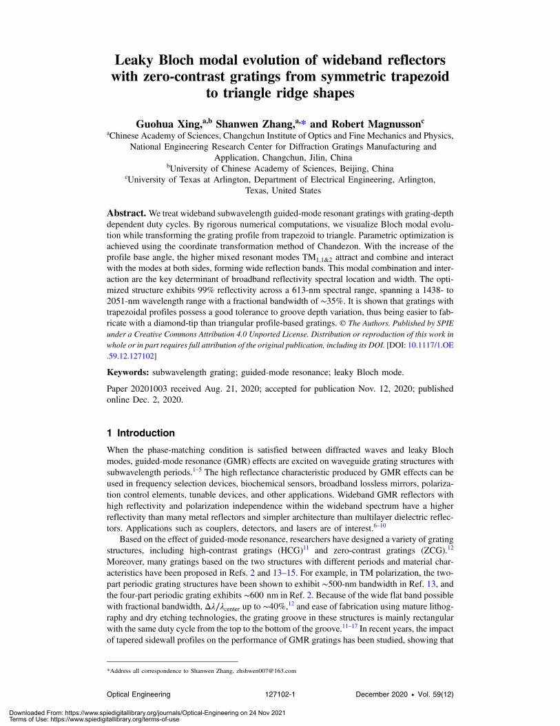
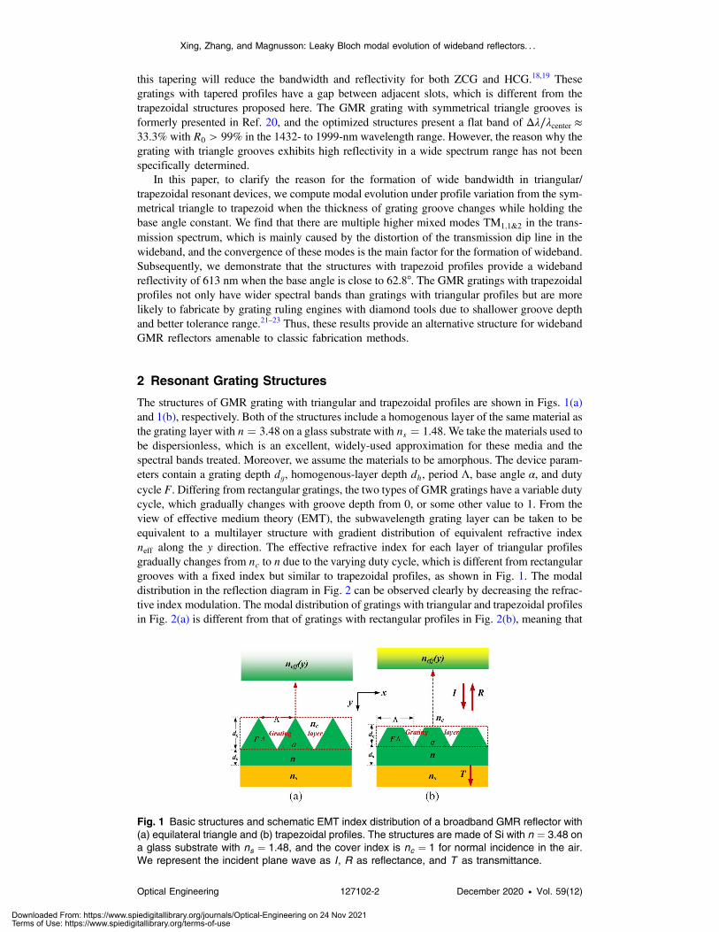
The structures of GMR grating with triangular and trapezoidal profiles are shown in Figs. 1(a)and 1(b), respectively. Both of the structures include a homogenous layer of the same material asthe grating layer with n ¼ 3.48 on a glass substrate with ns ¼ 1.48. We take the materials used tobe dispersionless, which is an excellent, widely-used approximation for these media and thespectral bands treated. Moreover, we assume the materials to be amorphous. The device param-eters contain a grating depth dg, homogenous-layer depth dh, period Λ, base angle α, and dutycycle F. Differing from rectangular gratings, the two types of GMR gratings have a variable dutycycle, which gradually changes with groove depth from 0, or some other value to 1. From theview of effective medium theory (EMT), the subwavelength grating layer can be taken to beequivalent to a multilayer structure with gradient distribution of equivalent refractive indexneff along the y direction. The effective refractive index for each layer of triangular profilesgradually changes from nc to n due to the varying duty cycle, which is different from rectangulargrooves with a fixed index but similar to trapezoidal profiles, as shown in Fig. 1. The modaldistribution in the reflection diagram in Fig. 2 can be observed clearly by decreasing the refrac-tive index modulation. The modal distribution of gratings with triangular and trapezoidal profilesin Fig. 2(a) is different from that of gratings with rectangular profiles in Fig. 2(b), meaning that
Fig. 1 Basic structures and schematic EMT index distribution of a broadband GMR reflector with(a) equilateral triangle and (b) trapezoidal profiles. The structures are made of Si with n ¼ 3.48 ona glass substrate with ns ¼ 1.48, and the cover index is nc ¼ 1 for normal incidence in the air.We represent the incident plane wave as I, R as reflectance, and T as transmittance.
Xing, Zhang, and Magnusson: Leaky Bloch modal evolution of wideband reflectors. . .
Optical Engineering 127102-2 December 2020 • Vol. 59(12)
Downloaded From: https://www.spiedigitallibrary.org/journals/Optical-Engineering on 24 Nov 2021Terms of Use: https://www.spiedigitallibrary.org/terms-of-use
the former slope more severely than the latter. The reason for the vertical mode loci in Fig. 2(a)is the dominance of the sublayer in the case of the triangular structure.
3 Theoretical Analysis
The optimization for these parameters of the GMR devices is achieved using the softwareDELTA based on the C-method.24,25 DELTA26 was developed by Lifeng Li at TsinghuaUniversity, and the software is used to simulate the surface relief diffraction gratings withan arbitrary refractive index. In this paper, we assume that the polarization of the incident planewave is TM, that is, the electric-field vector is in the xy plane.
3.1 Distribution of Guided-Mode Resonances for Gratings with EquilateralTriangle Profiles
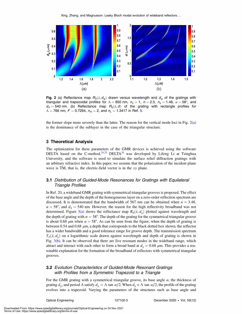
In Ref. 20, a wideband GMR grating with symmetrical triangular grooves is proposed. The effectof the base angle and the depth of the homogeneous layer on a zero-order reflection spectrum arediscussed. It is demonstrated that the bandwidth of 567 nm can be obtained when n ¼ 3.48,α ¼ 58°, and dh ¼ 540 nm. However, the reason for the high reflectivity broadband was notdetermined. Figure 3(a) shows the reflectance map R0ðλ; dgÞ plotted against wavelength andthe depth of grating with α ¼ 58°. The depth of the grating for the symmetrical triangular grooveis about 0.68 μm when α ¼ 58°. As can be seen from the figure, when the depth of grating isbetween 0.54 and 0.68 μm, a depth that corresponds to the black dotted box shown, the reflectorhas a wider bandwidth and a good tolerance range for groove depth. The transmission spectrumT0ðλ; dgÞ on a logarithmic scale drawn against wavelength and depth of grating is shown inFig. 3(b). It can be observed that there are five resonant modes in the wideband range, whichattract and interact with each other to form a broad band at dg ¼ 0.68 μm. This provides a rea-sonable explanation for the formation of the broadband of reflectors with symmetrical triangulargrooves.
3.2 Evolution Characteristics of Guided-Mode Resonant Gratingswith Profiles from a Symmetric Trapezoid to a Triangle
For the GMR grating with a symmetrical triangular groove, its base angle α, the thickness ofgrating dg, and period Λ satisfy dg ¼ Λ tan α∕2. When dg < Λ tan α∕2, the profile of the gratingevolves into a trapezoid. Varying the parameters of the structures such as base angle and
Fig. 2 (a) Reflectance map R0ðλ; dgÞ drawn versus wavelength and dg of the gratings withtriangular and trapezoidal profiles for Λ ¼ 850 nm, nc ¼ 1, n ¼ 2.5, ns ¼ 1.48, α ¼ 58°, anddh ¼ 540 nm. (b) Reflectance map R0ðλ; dÞ of the grating with rectangle profiles forΛ ¼ 766 nm, F ¼ 0.7264, nH ¼ 2, and nL ¼ 1.3417 in Ref. 5.
Xing, Zhang, and Magnusson: Leaky Bloch modal evolution of wideband reflectors. . .
Optical Engineering 127102-3 December 2020 • Vol. 59(12)
Downloaded From: https://www.spiedigitallibrary.org/journals/Optical-Engineering on 24 Nov 2021Terms of Use: https://www.spiedigitallibrary.org/terms-of-use
thickness of grating, the number, and location of resonant modes will change, so a differentreflection bandwidth will be observed in the reflection spectrum.
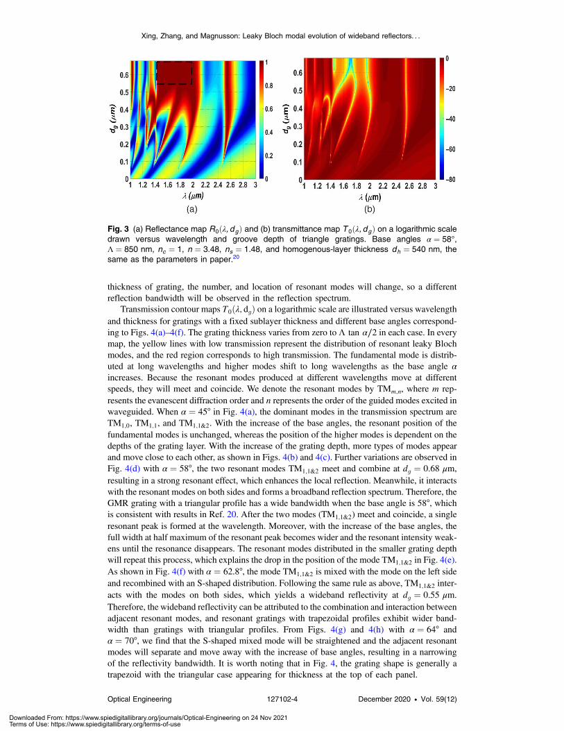
Transmission contour maps T0ðλ; dgÞ on a logarithmic scale are illustrated versus wavelengthand thickness for gratings with a fixed sublayer thickness and different base angles correspond-ing to Figs. 4(a)–4(f). The grating thickness varies from zero to Λ tan α∕2 in each case. In everymap, the yellow lines with low transmission represent the distribution of resonant leaky Blochmodes, and the red region corresponds to high transmission. The fundamental mode is distrib-uted at long wavelengths and higher modes shift to long wavelengths as the base angle αincreases. Because the resonant modes produced at different wavelengths move at differentspeeds, they will meet and coincide. We denote the resonant modes by TMm;n, where m rep-resents the evanescent diffraction order and n represents the order of the guided modes excited inwaveguided. When α ¼ 45° in Fig. 4(a), the dominant modes in the transmission spectrum areTM1;0, TM1;1, and TM1;1&2. With the increase of the base angles, the resonant position of thefundamental modes is unchanged, whereas the position of the higher modes is dependent on thedepths of the grating layer. With the increase of the grating depth, more types of modes appearand move close to each other, as shown in Figs. 4(b) and 4(c). Further variations are observed inFig. 4(d) with α ¼ 58°, the two resonant modes TM1;1&2 meet and combine at dg ¼ 0.68 μm,resulting in a strong resonant effect, which enhances the local reflection. Meanwhile, it interactswith the resonant modes on both sides and forms a broadband reflection spectrum. Therefore, theGMR grating with a triangular profile has a wide bandwidth when the base angle is 58°, whichis consistent with results in Ref. 20. After the two modes (TM1;1&2) meet and coincide, a singleresonant peak is formed at the wavelength. Moreover, with the increase of the base angles, thefull width at half maximum of the resonant peak becomes wider and the resonant intensity weak-ens until the resonance disappears. The resonant modes distributed in the smaller grating depthwill repeat this process, which explains the drop in the position of the mode TM1;1&2 in Fig. 4(e).As shown in Fig. 4(f) with α ¼ 62.8°, the mode TM1;1&2 is mixed with the mode on the left sideand recombined with an S-shaped distribution. Following the same rule as above, TM1;1&2 inter-acts with the modes on both sides, which yields a wideband reflectivity at dg ¼ 0.55 μm.Therefore, the wideband reflectivity can be attributed to the combination and interaction betweenadjacent resonant modes, and resonant gratings with trapezoidal profiles exhibit wider band-width than gratings with triangular profiles. From Figs. 4(g) and 4(h) with α ¼ 64° andα ¼ 70°, we find that the S-shaped mixed mode will be straightened and the adjacent resonantmodes will separate and move away with the increase of base angles, resulting in a narrowingof the reflectivity bandwidth. It is worth noting that in Fig. 4, the grating shape is generally atrapezoid with the triangular case appearing for thickness at the top of each panel.
Fig. 3 (a) Reflectance map R0ðλ; dgÞ and (b) transmittance map T 0ðλ; dgÞ on a logarithmic scaledrawn versus wavelength and groove depth of triangle gratings. Base angles α ¼ 58°,Λ ¼ 850 nm, nc ¼ 1, n ¼ 3.48, ns ¼ 1.48, and homogenous-layer thickness dh ¼ 540 nm, thesame as the parameters in paper.20
Xing, Zhang, and Magnusson: Leaky Bloch modal evolution of wideband reflectors. . .
Optical Engineering 127102-4 December 2020 • Vol. 59(12)
Downloaded From: https://www.spiedigitallibrary.org/journals/Optical-Engineering on 24 Nov 2021Terms of Use: https://www.spiedigitallibrary.org/terms-of-use

Fig. 4 Transmittance map T 0ðλ; dgÞ on a logarithmic scale drawn versus wavelength and thick-ness of grating with triangular and trapezoidal profiles with a fixed period Λ ¼ 850 nm and sub-layer thickness dh ¼ 540 nm. Eight different base angles α are considered to establish the modedynamics and attendant reflectance spectra. (a) α ¼ 45°; (b) α ¼ 51°; (c) α ¼ 54°; (d) α ¼ 58°;(e) α ¼ 61°; (f) α ¼ 62.8°; (g) α ¼ 64°; (h) α ¼ 70°.
Xing, Zhang, and Magnusson: Leaky Bloch modal evolution of wideband reflectors. . .
Optical Engineering 127102-5 December 2020 • Vol. 59(12)
Downloaded From: https://www.spiedigitallibrary.org/journals/Optical-Engineering on 24 Nov 2021Terms of Use: https://www.spiedigitallibrary.org/terms-of-use
The resonance structure architecture studied here has a very complex design. There is not asimple theoretical model or analytical formulation available that would bring improved trans-parency to the details of the physical processes at work. The multiple modes supported existbetween a flat surface at the lower side and a corrugated surface at the top side. The guidingconditions differ dramatically from those of a slab waveguide or a grating between parallelplanes that is the usual configuration. Nevertheless, apart from the complex mode distributiondetails, the lateral Bloch modes radiate across a bandwidth such that if the reradiated waves arein phase, wideband forms. This has been shown by Lalanne et al.3 in a far simpler case. Theprinciples divulged therein are still at work in this complex case.
3.3 Effect of the Homogeneous Thickness on Broadband ReflectionSpectrum of the GMR Gratings with the Symmetric Trapezoidand Triangle Ridge Shape
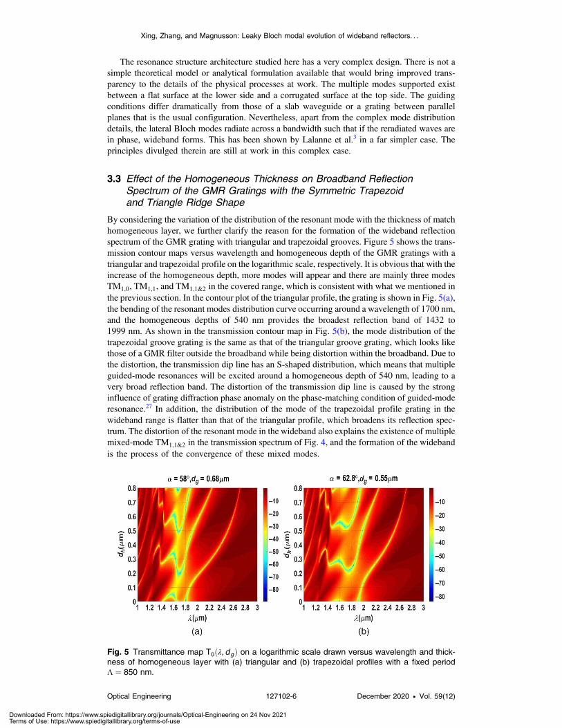
By considering the variation of the distribution of the resonant mode with the thickness of matchhomogeneous layer, we further clarify the reason for the formation of the wideband reflectionspectrum of the GMR grating with triangular and trapezoidal grooves. Figure 5 shows the trans-mission contour maps versus wavelength and homogeneous depth of the GMR gratings with atriangular and trapezoidal profile on the logarithmic scale, respectively. It is obvious that with theincrease of the homogeneous depth, more modes will appear and there are mainly three modesTM1;0, TM1;1, and TM1;1&2 in the covered range, which is consistent with what we mentioned inthe previous section. In the contour plot of the triangular profile, the grating is shown in Fig. 5(a),the bending of the resonant modes distribution curve occurring around a wavelength of 1700 nm,and the homogeneous depths of 540 nm provides the broadest reflection band of 1432 to1999 nm. As shown in the transmission contour map in Fig. 5(b), the mode distribution of thetrapezoidal groove grating is the same as that of the triangular groove grating, which looks likethose of a GMR filter outside the broadband while being distortion within the broadband. Due tothe distortion, the transmission dip line has an S-shaped distribution, which means that multipleguided-mode resonances will be excited around a homogeneous depth of 540 nm, leading to avery broad reflection band. The distortion of the transmission dip line is caused by the stronginfluence of grating diffraction phase anomaly on the phase-matching condition of guided-moderesonance.27 In addition, the distribution of the mode of the trapezoidal profile grating in thewideband range is flatter than that of the triangular profile, which broadens its reflection spec-trum. The distortion of the resonant mode in the wideband also explains the existence of multiplemixed-mode TM1;1&2 in the transmission spectrum of Fig. 4, and the formation of the widebandis the process of the convergence of these mixed modes.
Fig. 5 Transmittance map T0ðλ; dgÞ on a logarithmic scale drawn versus wavelength and thick-ness of homogeneous layer with (a) triangular and (b) trapezoidal profiles with a fixed periodΛ ¼ 850 nm.
Xing, Zhang, and Magnusson: Leaky Bloch modal evolution of wideband reflectors. . .
Optical Engineering 127102-6 December 2020 • Vol. 59(12)
Downloaded From: https://www.spiedigitallibrary.org/journals/Optical-Engineering on 24 Nov 2021Terms of Use: https://www.spiedigitallibrary.org/terms-of-use
4 Results
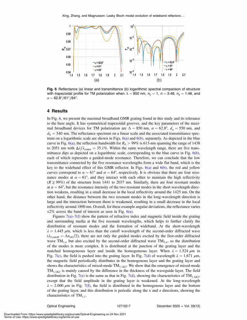
In Fig. 6, we present the maximal broadband GMR grating found in this study and its toleranceto the base angle. It has symmetrical trapezoidal grooves, and the key parameters of the maxi-mal broadband devices for TM polarization are Λ ¼ 850 nm, α ¼ 62.8°, dg ¼ 550 nm, anddh ¼ 540 nm. The reflectance spectrum on a linear scale and the associated transmittance spec-trum on a logarithmic scale are shown in Figs. 6(a) and 6(b), separately. As depicted in the bluecurve in Fig. 6(a), the reflection bandwidth for R0 > 99% is 613-nm spanning the range of 1438to 2051 nm with Δλ∕λcenter ¼ 35.1%. Within the same wavelength range, there are five trans-mittance dips as depicted on a logarithmic scale, corresponding to the blue curve in Fig. 6(b),each of which represents a guided-mode resonance. Therefore, we can conclude that the lowtransmittance connected by the five resonance wavelengths form a wide flat band, which is thekey to the wideband effect of this GMR reflector. In Figs. 6(a) and 6(b), the red and yellowcurves correspond to α ¼ 61° and α ¼ 64°, respectively. It is obvious that there are four reso-nance modes at α ¼ 61°, and they interact with each other to maintain the high reflectivity(R ≥ 99%) of the structure from 1441 to 2037 nm. Similarly, there are four resonant modesat α ¼ 64°, but the resonance intensity of the two resonant modes in the short wavelength direc-tion weakens, resulting in a small decrease in the local reflectivity around the 1425 nm. On theother hand, the distance between the two resonant modes in the long-wavelength direction islarge and the interaction between them is weakened, resulting in a small decrease in the localreflectivity around 1890 nm. Overall, for these example angular deviations, the reflectance varies<2% across the band of interest as seen in Fig. 6(a).
Figures 7(a)–7(f) show the pattern of refractive index and magnetic field inside the gratingand surrounding media at the five resonant wavelengths, which helps to further clarify thedistribution of resonant modes and the formation of wideband. At the short-wavelengthλ ¼ 1.445 μm, which is less than the cutoff wavelength of the second-order diffracted wave(λ2;cutoff ¼ Λneff∕2), there are not only the guided modes excited by the first-order diffractedwave TM1;n but also excited by the second-order diffracted wave TM2;n, so the distributionof the modes is more complex. It is distributed at the junction of the grating layer and thematched homogeneous layer and inside the homogeneous layer. When λ ¼ 1.524 μm inFig. 7(c), the field is pushed into the grating layer. In Fig. 7(d) of wavelength λ ¼ 1.671 μm,the magnetic field periodically distributes in the homogenous layer and the grating layer andshows the characteristics of mixed-mode TM1;1&2. We show that the emergence of mixed-modeTM1;1&2 is mainly caused by the difference in the thickness of the waveguide layer. The fielddistribution in Fig. 7(e) is the same as that in Fig. 7(d), showing the characteristics of TM1;1&2,except that the field amplitude in the grating layer is weakened. At the long-wavelengthλ ¼ 2.000 μm in Fig. 7(f), the field is distributed in the homogenous layer and the bottomof the grating layer, and this distribution is periodic along the x and z directions, showing thecharacteristics of TM1;1.
Fig. 6 Reflectance (a) linear and transmittance (b) logarithmic spectral comparison of structurewith trapezoidal profile for TM polarization when Λ ¼ 850 nm, nc ¼ 1, n ¼ 3.48, ns ¼ 1.48, andα ¼ 62.8°∕61°∕64°.
Xing, Zhang, and Magnusson: Leaky Bloch modal evolution of wideband reflectors. . .
Optical Engineering 127102-7 December 2020 • Vol. 59(12)
Downloaded From: https://www.spiedigitallibrary.org/journals/Optical-Engineering on 24 Nov 2021Terms of Use: https://www.spiedigitallibrary.org/terms-of-use

Resonant wideband reflectors, in general, can be compared to Bragg reflectors. DistributedBragg reflectors (DBRs), which consist of multiple layers of materials with alternating high andlow refractive index, often 10 to 100 layers, have been widely used as high reflectivity mirrors insurface-emitting lasers, for example. The main practical difference between the resonant reflec-tors and DBRs lies in the layer count. Other attributes have been compared as discussed in detailin the literature.28,29
5 Conclusion
In this paper, broadband GMR gratings with a depth-dependent duty cycle, including symmet-rical triangular and trapezoidal profiles, are designed and their modal evolution simulated undera variable base angle. A grating with a trapezoidal profile is found to provide a 613-nm spectralwidth for 99% reflectance, a ∼46-nm enhancement relative to triangular profiles.20 From the
Fig. 7 (a) The distribution of refractive index and amplitude of the internal magnetic field in theGMR grating with trapezoidal profiles and surrounding media at the resonance wavelengths forΛ ¼ 850 nm, α ¼ 62.8°, dh ¼ 540 nm and dg ¼ 550 nm. (b) λ ¼ 1.445 μm; (c) λ ¼ 1.524 μm;(d) λ ¼ 1.671 μm; (e) λ ¼ 1.769 μm; (f) λ ¼ 2.000 μm.
Xing, Zhang, and Magnusson: Leaky Bloch modal evolution of wideband reflectors. . .
Optical Engineering 127102-8 December 2020 • Vol. 59(12)
Downloaded From: https://www.spiedigitallibrary.org/journals/Optical-Engineering on 24 Nov 2021Terms of Use: https://www.spiedigitallibrary.org/terms-of-use

transmission spectrum, we observe the combination of mixed modes TM1;1&2 and the interactionwith other modes, with the increase of the base angle, explaining why quasi-equilateral triangularand trapezoidal grating profiles achieve broadband features at optimized parametric values. Asthe base angle continues to increase, the mixed-mode with S-shaped distribution will graduallystraighten and reduce the bandwidth. For the complex device architectures treated here, thereexist no simple analytical formulations; hence, rigorous numerical methods are essential for thediscovery of functional devices with superior performance. With a shallower groove depth andbetter tolerance range, gratings with trapezoidal profiles are easier to be fabricated by gratingruling engines that would be imbued with a high-resolution diamond-tipped scribes. Thus, theconclusions of this study have practical ramifications.
Acknowledgments
The authors acknowledge supports from the Fudan University-CIOMP Joint Fund (Grant No.Y9S133H190), and the International cooperation project (Grant No. Y8E43WH). The authorsdeclare no conflicts of interest.
References
1. D. Rosenblatt, A. Sharon, and A. A. Friesem, “Resonant grating waveguide structures,”IEEE J. Quantum Electron. 33(11), 2038–2059 (1997).
2. Y. Ding and R. Magnusson, “Resonant leaky-mode spectral-band engineering and deviceapplications,” Opt. Express 12(23), 5661–5674 (2004).
3. P. Lalanne, J. P. Hugonin, and P. Chavel, “Optical properties of deep lamellar gratings:a coupled Bloch-mode insight,” J. Lightwave Technol. 24(6), 2442–2449 (2006).
4. Y. H. Ko and R. Magnusson, “Wideband dielectric metamaterial reflectors: Mie scattering orleaky Bloch mode resonance?” Optica 5(3), 289–294 (2018).
5. R. Magnusson and M. Shokooh-Saremi, “Physical basis for wideband resonant reflectors,”Opt. Express 16(5), 3456–3462 (2008).
6. S. S. Wang and R. Magnusson, “Theory and applications of guided-mode resonance filters,”Appl. Opt. 32(14), 2606–2613 (1993).
7. M. C. Y. Huang, Y. Zhou, and C. J. Chang-Hasnain, “A surface-emitting laser incorporatinga high index-contrast subwavelength grating,” Nat. Photonics 1, 119–122 (2007).
8. P. Cheben et al., “A broad-band waveguide grating coupler with a subwavelength gratingmirror,” IEEE Photonics Technol. Lett. 18(1), 13–15 (2006).
9. C. C. Wang and S. D. Lin, “Resonant cavity-enhanced quantum-dot infrared photodetectorswith sub-wavelength grating mirror,” J. Appl. Phys. 113, 213108 (2013).
10. C. P. Sturmberg et al., “Fano resonances of dielectric gratings: symmetries and broadbandfiltering,” Opt. Express 23(24), A1672–A1686 (2015).
11. C. F. R. Mateus et al., “Broad-band mirror (1.12 − 1.62 μm) using a subwavelengthgrating,” IEEE Photonics Technol. Lett. 16(7), 1676–1678 (2004).
12. R. Magnusson, “Wideband reflectors with zero-contrast gratings,” Opt. Lett. 39(15),4337–4340 (2014).
13. C. F. R. Mateus et al., “Ultrabroadband mirror using low-index cladded subwavelengthgrating,” IEEE Photonics Technol. Lett. 16(2), 518–520 (2004).
14. A. Taghizadeh et al., “Hybrid grating reflector with high reflectivity and broad bandwidth,”Opt. Express 22(18), 21175–21184 (2014).
15. M. Shokooh-Saremi and R. Magnusson, “Wideband leaky-mode resonance reflectors:influence of grating profile and sublayers,” Opt. Express 16(22), 18249–18263 (2008).
16. H. Wu et al., “A multilayer-based high-performance multisubpart profile grating reflector,”IEEE Photonics Technol. Lett. 22(4), 203–205 (2010).
17. H. Wu et al., “A wideband reflector realized by a subwavelength multi-subpart profilegrating structure,” J. Opt. 15, 035703 (2013).
18. W. Yu, M. Ye, and Y. S. Yi, “Impacts of tapered sidewall profile on subwavelength gratingwideband reflectors,” J. Nanophotonics 9, 093058 (2015).
Xing, Zhang, and Magnusson: Leaky Bloch modal evolution of wideband reflectors. . .
Optical Engineering 127102-9 December 2020 • Vol. 59(12)
Downloaded From: https://www.spiedigitallibrary.org/journals/Optical-Engineering on 24 Nov 2021Terms of Use: https://www.spiedigitallibrary.org/terms-of-use

19. X. Y. Wenxi and Y. Yi, “Impacts of tapered sidewall profiles with high aspect ratio on sub-wavelength grating structure,” IEEE Photonics Technol. Lett. 27(13), 1437–1440 (2015).
20. S. Zhang, Y. H. Ko, and R. Magnusson, “Broadband guided-mode resonant reflectors withquasi-equilateral triangle grating profiles,” Opt. Express 25(23), 28451–28458 (2017).
21. X. Li et al., “300 mm ruling engine producing gratings and Echelles under interferometriccontrol in China,” Appl. Opt. 54(7), 1819–1826 (2015).
22. Jirigalantu et al., “Ruling of Echelles and gratings with a diamond tool by the torqueequilibrium method,” Appl. Opt. 55(28), 8082–8088 (2016).
23. S. Zhang et al., “Groove shape characteristics of Echelle gratings with high diffractionefficiency,” Opt. Commun. 387, 401–404 (2017).
24. J. Chandezon, D. Maystre, and G. Raoult, “A new theoretical method for diffraction gratingsand its numerical application,” J. Opt. 11(4), 235–241 (1980).
25. J. Chandezon et al., “Multicoated grating: a differential formalism applicable in the entireoptical region,” J. Opt. Soc. Am. 72(7), 839–846 (1982).
26. L. Li et al., “Rigorous and efficient grating-analysis method made easy for opticalengineers,” Appl. Opt. 38(2), 304–313 (1999).
27. G. C. Park, A. Taghizadeh, and, , and I. S. Chung, “Hybrid grating reflectors: origin ofultrabroad stopband,” Appl. Phys. Lett. 108(14), 141108 (2016).
28. K. J. Lee and R. Magnusson, “Single-layer resonant high reflector in TE polarization: theoryand experiment,” IEEE Photonics J. 3(1), 123–129 (2011).
29. M. Niraula, J. W. Yoon, and R. Magnusson, “Single-layer optical bandpass filter technol-ogy,” Opt. Lett. 40(21), 5062–5065 (2015).
Guohua Xing is a PhD student at the University of the Chinese Academy of Sciences. Shereceived her BS degree in applied physics from Yantai University in 2018. Her current researchinterests include GMR gratings.
Biographies for the other authors are not available.
Xing, Zhang, and Magnusson: Leaky Bloch modal evolution of wideband reflectors. . .
Optical Engineering 127102-10 December 2020 • Vol. 59(12)
Downloaded From: https://www.spiedigitallibrary.org/journals/Optical-Engineering on 24 Nov 2021Terms of Use: https://www.spiedigitallibrary.org/terms-of-use