leaflet doorscan-2p / 4p-1600 -...
TRANSCRIPT

DoorScan-2P / 4P-1600 English
! TYPE TESTED
Active infrared sensor for approach detection at industrial doors up to 1600 mm wide Translation of original operating instructions for device version V.02.
Safety InformationThe device must only be operated with Safety Extra Low Voltage (SELV) which complies with the stipulations in the safety standards based on IEC 60950.This device must be installed and maintained only by qualified, trained personnel.
Delivery package
A) Mounting sensor strip
1. If necessary, cut the sensor strip to the required length (using saw).
2. Place the sensor strip in the required mounting position.Mounting height: 1500-3500 mm
3. Align the mounting holes with the groove in the sensor strip.
4. Screw on the sensor strip.Observe maximum screw head height: 3.5 mm.
5. Repeat steps 1-4 on the opposite side of the door.
6. Drill thru-hole for connecting the hinge side and side opposite hinge.Diameter: approx. 8 mm
Note: Bore on left of interface facilitates cable routing.
50 mm 50 mm
dia. 8 mm
Sensor strip (2x)
End caps with mounting set (4x)
Sensor apertures (2x)
Cable holders (4x)
Transmitter module (2x) Receiver module (2x)
Interface module (1x)
Module connecting cable - ribbon cable (2x)
Door transition cable for door control with accessories (1x)
Connecting cable between hinge side and side opposite hinge (1x)
Operating instructions
The number of parts may vary depending on the version
Transmitter module (2x) Receiver module (2x)
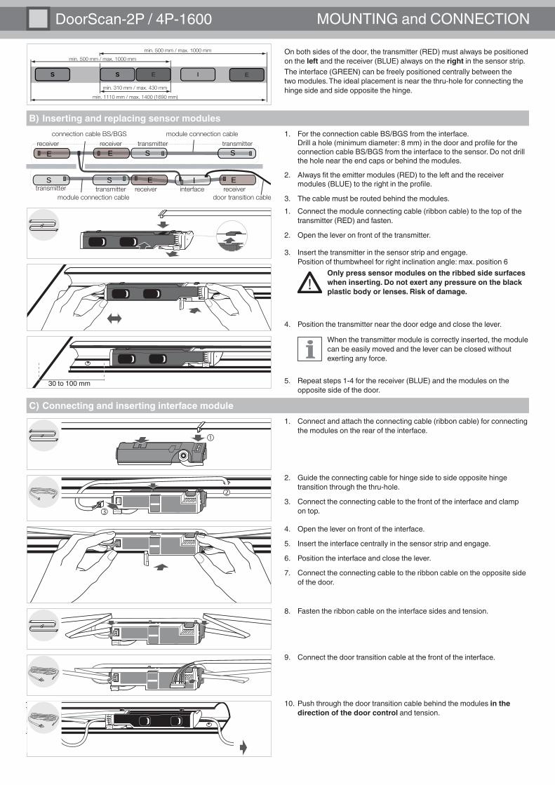
DoorScan-2P / 4P-1600 MOUNTING and CONNECTION
C) Connecting and inserting interface module1. Connect and attach the connecting cable (ribbon cable) for connecting
the modules on the rear of the interface.
2. Guide the connecting cable for hinge side to side opposite hinge transition through the thru-hole.
3. Connect the connecting cable to the front of the interface and clamp on top.
4. Open the lever on front of the interface.
5. Insert the interface centrally in the sensor strip and engage.
6. Position the interface and close the lever.
7. Connect the connecting cable to the ribbon cable on the opposite side of the door.
9. Connect the door transition cable at the front of the interface.
8. Fasten the ribbon cable on the interface sides and tension.
B) Inserting and replacing sensor modules
1. Connect the module connecting cable (ribbon cable) to the top of the transmitter (RED) and fasten.
2. Open the lever on front of the transmitter.
4. Position the transmitter near the door edge and close the lever.
5. Repeat steps 1-4 for the receiver (BLUE) and the modules on the opposite side of the door.
!Only press sensor modules on the ribbed side surfaces when inserting. Do not exert any pressure on the black plastic body or lenses. Risk of damage.
30 to 100 mm
10. Push through the door transition cable behind the modules in the direction of the door control and tension.
S S E E I
min. 500 mm / max. 1000 mm
min. 500 mm / max. 1000 mm
min. 310 mm / max. 430 mm
min. 1110 mm / max. 1400 (1690 mm)
On both sides of the door, the transmitter (RED) must always be positioned on the left and the receiver (BLUE) always on the right in the sensor strip.The interface (GREEN) can be freely positioned centrally between the two modules. The ideal placement is near the thru-hole for connecting the hinge side and side opposite the hinge.
3. Insert the transmitter in the sensor strip and engage.Position of thumbwheel for right inclination angle: max. position 6
When the transmitter module is correctly inserted, the module can be easily moved and the lever can be closed without exerting any force.
�
�
�
module connection cable
module connection cable
connection cable BS/BGS
door transition cable
IS S
S SE E
E Etransmitter receiver interface receiver transmitter
transmitter transmitter receiver receiver 1. For the connection cable BS/BGS from the interface.
Drill a hole (minimum diameter: 8 mm) in the door and profile for the connection cable BS/BGS from the interface to the sensor. Do not drill the hole near the end caps or behind the modules.
2. Always fit the emitter modules (RED) to the left and the receiver modules (BLUE) to the right in the profile.
3. The cable must be routed behind the modules.

English
D) Door control connection
Option A: vertical
1.
3. Insert the tension relief into the end cap cut-out.
Option B: horizontal
1.
3. Push the tension relief through the hole until it engages.
F) Closing sensor
1. Fit cable holders.
2. Insert sensor aperture.
3. Screw on end caps.
E) Adjusting and teaching in sensor
1. Depending on the position of the door control, select the appropriate end cap (right/left) for the cable exit in order to prepare the cable duct.Depending on the subsequent routing of the cable toward the door control, the end caps offer two cable routing options.
L R
4. Push the cable sheathing onto the tension relief using a large Phillips screwdriver and push in the hollow rivet.
2. Break out the predetermined end-cap cut-out using pliers.
2. Break out the internal dome using a suitable screwdriver.
The door transition cable is routed downward through the end cap.
The door transition cable is routed straight through the end cap.
or
5. Fit the prepared end cap onto the sensor strip and feed through the door transition cable.
6. Connect the door transition cable to the door control and switch on the supply voltage.
BGS
OUT
BS O
UTST
AND
BYTE
ST 0 V
24 V
6 5 4 3 2 1
See DoorScan settings on following double page.
� 24 V ð brown (BN)� 0 V ð blue (BU)� TEST ð gray (GY)� STANDBY ð pink (PK)� BS OUT ð black (BK)� BGS OUT ð white (WH)
�
�
� � �

DoorScan-2P / 4P-1600 SETTINGS
* Default setting
Adjusting the inclination angleTurn the thumbwheel on the transmitter and then on the receiver until the appropriate setting is displayed at the line marking.
0 ð smallest angle 18 ð largest angle
Setting DIP switch row 1 and row 21. Set DIP switch row 1 and row 2 on interface as described below.
Combinations of the individual options may be used. When switching a DIP switch, the relevant LED flashes in the LED field. The changes are not saved while the LED is still flashing.
2. Press the Teach button (RED) 1x to save the settings.
66
44
88
R BGS
ON
BOOST GRID
L BS ON ON
1 2 3 4
TST-
TST+
BGS-DON
BGS-L
After saving, press the Teach button once at any time to see the settings.
1 2 3 4
Recommended settings according to DIN 18650/EN 16005:• Position 6 for 1900-2200 mm mounting height (default setting)• Position 5 for 2500 mm mounting height• Position 4 for 3000 mm mounting height• Position 3 for 3500 mm mounting height
The transmitter and receiver must always be adjusted the same.
Row
1
DIP 1 (L/R) DIP 2 (BS/BGS) DIP 3 (BOOST mode) DIP 4 (GRID mode)Secondary closing edge, right or
left of interfaceInterface on side opposite hinge
(BGS) or on hinge side (BS)Increased sensitivity ** Deep grid ***
Right* Left Side opposite hinge* (BGS)
Hinge side (BS) No* Yes No* Yes
OFF OFF OFF OFF OFF OFF OFF OFF
Row
2
DIP 1 (TST+/TST-) DIP 2 (BGS-L/BGS-D)Test signal polarity BGS Out switching mode
Test at 0 V -* Test at 24 V + Dark ON Light ON*
OFF OFF OFF
ON
OFF
ON
ONOFF
ON ON ON
ON ON ON ON ON ON ON
TEACH
1x
DIP switches – row 2
DIP switches – row 1
LED field
DoorScan detection fieldThe sensor uses an active-infrared principle and forms a continuous rectangular detection field on each side of the door. If a person or object breaks one or more of the light beams, the sensor’s output is triggered.The detection field composed of 10 beams adapts automatically to the door width, whereby the sensor disables any superfluous beams. The slightly inclined position of the outer beams means that the main and secondary closing edges of the doors are more secure. The sensor system is modular and can be adapted to a wide range of door widths and ambient conditions as follows:
** BOOST mode = increased sensitivity: optional settingUse e.g. for large mounting heights, dark floors or chromed doormats. The response time is increased to 200 ms.
***GRID mode = application for deep grid: optional settingTeach-in process: Cover the grid (cardboard/paper/carpet) so that at least two beams of the sensor mo-dule impinge on the cover. If more than one transmitter/receiver module is used on the relevant door side, the grid must be covered so that all the transmitter beams impinge on the cover during teach-in of the floor surface.
DIP 3 and DIP 4No function
Note on GRID mode: When GRID mode is active, signal tracking is disabled and the detection height is set to approx. 200 mm. GRID mode should therefore be activated even in the case of ramps and steps located within the detection area.
* Default setting

English
Display elementsReceiverInterface
During teach-in, the sensor first learns the floor surface and then, during a subsequent door opening run, the detection area.
Commissioning (teaching and blanking)
Teach LED (YELLOW) on interface lights up or flickers:Sensor is ready for teach-in.
1. Press Teach button (RED): 1x if LED is lit up / 2x if LED is flickering
BLANK
STATUS
R
TST-
TST+BGS
BGS-D
ON
ON
BGS-LBOOST GRID
L BS ON ON
1 2 3 4
1 2 3 4 TEACH
BGS
OUT
BS O
UTST
AND
BYTE
ST 0 V
24 V
6 5 4 3 2 1 64
8
Teach LED flashes slowly: Floor surface is being taught in.
Teach LED flashes rapidly: Teach-in of the floor surface is completed. Teach-in of the surroundings begins.
Blank LED (green) StatusLights up Blanking active
Does not light up Blanking inactive or only partly active
DIP LED (green) StatusLights up DIP in ON positionDoes not light up DIP in OFF positionFlashes slowly (1Hz) Setting changed
Status LED (red) Status
Lights up Detection or STANDBY mode active
Flashes Fault indicationDoes not light up No detection
Teach LED (yellow) StatusLights up Teach mode readyFlashes slowly (1Hz) Teach in floor surfaceFlashes rapidly (2 Hz)
Teach-in blanking (door opening)
Flickers (8Hz) Teach-in requiredDoes not light up Sensor ready for operation
Status LED (red) StatusLights up DetectionFlashes Fault indicationDoes not light up No detection
!Before teach-in, remove all objects from the door area that are not part of the normal surroundings and leave the sensor detection area.
TEACH
TEACH
TEACH
TEACH
or
2. Start a door opening run at standard speed within 20 s (with button or remote control).During the door opening run, the surroundings, any walls present and the opposite door post are taught in.
3. Teach LED is off.
If the sensor detects walls in the detection area during door opening, these are also taught into the sensor and suppressed (blanking), in order to enable full door opening during subsequent operation. Following successful blanking, the sensor will operate correctly over the full door opening range If the wall contains elements that do not lend them-selves to blanking, the sensor permits blanking until these elements are detected.
If there is no wall located in the door area, the Blank LED is off. The sensor is ready for operation.
BLANK or
1x
!!Check the effectiveness of the detection field before closing the sensor.
If the red status LED flashes, see Fault indication on the following page.
If the LEDs flash after the teach-in process, the sensor is not ready for operation. See Fault indication and Application Notes on the following pages.
4. If there is a wall present in the door area:
ð
ð
ð
ð
ð
Teach-in process1.
2.
2 x
3.
4.• The Blank LED lights up: Wall was fully taught in.• The Blank LED is off: The wall was not fully taught in. If the door
does not open fully in this case, switch on wall suppression at the drive.
The sensor is ready for operation.

DoorScan-2P / 4P-1600 APPLICATION NOTES
Fault indications
Yellow teach LED on interface flickers
Red status LED on interface is off
Receiver LED off Receiver failure
System error in receiver
Transmitter and receiver module not correctly aligned to each other
Transmitter module failure
Grid in detection area
Receiver module defective
Interface module defective
Replace receiver module
Check contacts of all modules with ribbon cable Replace transmitter module
Activate Grid mode
Replace interface
Receiver LED flashes 4x
Red status LED on interface flashes 4x
Error after wall teach-in
Yellow teach LED on interface flickers
Red status LED on interface is on
Red status LED on interface flashes 3x
Receiver LED flashes 1x
Receiver LED flashes 1x
Receiver LED is on
Receiver LED flashes rapidly
Signal strength too low
Door or sensor profile warped
Very dark or reflective floor surface
Inclination angle of receiver module:a) reduce progressively until the sensor switches to detection, note the settingb) increase progressively until the sensor switches to detection, note the settingc) set to the mean of the two values
Activate Boost mode. Caution! The response time of the sensor is extended.
Wall is detected despite teach-in run
Yellow Teach LED on interface is off
Red status LED on interface is on
Receiver LED is on
Yellow Teach LED on interface is off
Red status LED on interface is on
Receiver LED is on
Door no longer closes after lengthy time in open position
There is a ramp in front of the door or the floor level is lower in the open position (-10 cm) than in the closed position
Activate Grid mode
Suppress sensor strip at door drive
Carry out wall teach-in run at higher door speed. The speed can be reduced again after the teach-in run
Carry out wall teach-in run at normal or higher door speed
Increase angle setting of transmitter and receiver modules (pos. ≥ 12)
Change DIP switch 1 setting
Receiver remains on detection even after detected object has been removed
There are bumps (> 5 cm) on the floor in the detection area
Incorrect assignment of interface to secondary closing edge
Angle of transmitter and receiver module set too steep on side opposite hinge
Door speed slower during teach-in run than during operation
No smooth wall
Fault during operation
Reversing speed higher than normal opening speed
Red status LED on interface is off
Red status LED on interface flashes rapidly
Yellow teach LED on interface is off
Yellow teach LED on interface flickers
Receiver module access violation
Incorrect assignment of interface to hinge side (BS) / side opposite hinge (BGS)
Repeat teach operation
Activate Grid mode and adapt floor level during teach operation is necessary
Remove object
Change DIP switch 2 setting
Repeat teach operation
Interface access violation (green DIP LEDs flash
Sensor on side opposite hinge is lower than on the hinge side (step, threshold)
Sensor on side opposite hinge detects object
Base width much too large
Object in detection field
Base width too large
Receiver LED flashes 1x
Receiver LED flashes 2x
Receiver LED flashes 3x
Red status LED on interface flashes 2x
Turn angle adjuster to same positionCheck that transmitter and receiver modules are correctly engaged in the profile and not subjected to any pressure through cables etc. Check transmitter and receiver modules for damage (concealed plastic tab at adjustment wheel), replace if necessary)
Reduce module distance
Remove object or increase distance to side wall reveal
Reduce module distance
Switch operating voltage off and on again Replace receiver module
Check contacts of all modules with ribbon cable Replace receiver module
Error after floor teach-in

English
Application Notes
Special doors (e.g. glass doors)If a cable cannot be routed through the door, install an interface on both door sides. For this purpose, an additional interface and an additional DoorScan Transfer Loop are required (see accessories).
Horizontal handles1. Position the transmitter and receiver as described in the mounting
instructions.
2. Set the inclination angle so that the detection field is located in front of the handle.
Narrow door frames with normal and rack-and-pinion door closers
In the case of narrow door frames with normal and rack-and-pinion door closers, transmitters and receivers can be operated in separate sensing strips.
Doors with door revealsOn doors with wide door reveals, the transmitter requires a sufficient clea-rance from the door reveals. At the standard mounting height of 1900-2100 mm, this clearance is approx. 170 mm. At greater mounting heights, the clearance increases to approx. 200 mm.The receiver can usually be positioned at a distance of 100 mm from the closing edge.
170 to 200 mm 100 mm
> 120 mm
25 to 30 mm
> 120 mm
25 to 30 mm25 to 30 mm
Transmitter 1
Transmitter 2
Transmitter 2
Transmitter 1
Receiver 1
Receiver 2
Receiver 2
Receiver 1
For further tips and tricks regarding application-related settings, please visit www.pepperl-fuchs.com
Vertical handlesSensor strip fits behind handle.The handle is positioned at a distance of less than 300 mm from the main closing edge.For standard-compliant protection according to DIN 18650/EN 16005 you additionally need 1 transmitter module, 1 receiver module and 1 connec-ting cable module (ribbon cable) for each door side --> (see Accessories).
Left handle1. Position the transmitter 1 as far to the left as possible.
2. Position transmitter 2 approx. 25–30 mm to the right of transmitter 1 or 10 mm to the right of the handle. Transmitter 2 must not be behind the handle.
3. Position receiver 2 approx. 100 mm from the secondary closing edge. Position receiver 1 approx. 25 - 30 mm to the left of receiver 2.
Right handle4. Position receiver 1 as far to the right as possible.
5. Position receiver 2 approx. 25–30 mm to the left of receiver 1 or 10 mm to the left of the handle. Receiver 2 must not be behind the handle.
6. Position transmitter 2 approx. 100 mm from the secondary closing edge.
7. Position transmitter 1 approx. 25 - 30 mm to the right of transmitter 2.
If teach-in is not possible in either case, increase the inclination angle or move the first transmitter. The door may, however, no longer be protected in accordance with DIN 18650/ EN 16005.
25 to 30 mm
Approx. 100 mm
Faults due to multiple sensors interfering with one anotherFor swinging doors that converge, e.g., with adjacent doors, undesirable stop signals may occur due to mutual interference if the measuring spots overlap. Overlap of the measuring spots can be minimized by moving each of the sensors. On double swinging doors, the sensors on the two swinging doors will not interfere with one another. It is not possible for multiple sensor systems to cause any danger by interfering with one another.

Functional principle Active infrared scanner with background evaluation
Mounting height min 1500 mm; max 3500 mm for vertical CA reference bodies
Light source IRED, 850 nmOperating voltage 24 VDC +/-20%Switching mode Hinge side (BS) light on / side opposite
hinge (BGS) can be switched to light on/dark on
Switching voltage/current npn / 30 V DC / max. 100 mACurrent consumption max 200 mAResponse time 52 ms / 200 ms in BOOST modeAmbient temperature -30 ... 60°CRelative humidity 25% .. 95%, non-condensingDegree of protection IP54 in accordance with EN60529Connection Connector strip with connecting cable,
6-wireMaterial Sensing strip: aluminum / End cap: PA /
Sensor aperture: PC
Function SettingDIP switches Row 1: Switch 1-4 down (OFF)
Row 2: Switch 1 down (OFF).Switch 2 up (ON)
Thumbwheel Position 0
Pepperl+Fuchs World HeadquartersPepperl+Fuchs GmbHLilienthalstrasse 200D-68307 Mannheim . Germany
E-mail: [email protected]
Asia Pacific HeadquartersPepperl+Fuchs Pte Ltd. . Singapore 139942E-mail: [email protected]
USA HeadquartersPepperl+Fuchs Inc. Twinsburg . USAE-mail: [email protected]
DOCT-2727A
Part no. 246732 12/2013
Technical data
Default settings
Contact
Accessories
Weather caps for protection against climatic conditions (can be cut to required length)DoorScan Weather Cap L1200 Length: 1200 mmDoorScan Weather Cap L1600 Length: 1600 mm
End cap setsDoorScan End Caps Standard end cap set (left/right)
Additional sensor modules for customized configurationsDoorScan-I/30 Interface moduleDoorScan-R Receiver moduleDoorScan-T Transmitter module
Connecting cableDoorScan Connection Cable 5p Module connecting cable - ribbon cable with 5 connectorsDoorScan Transfer Loop Door transition cable to door controlDoorScan Cable BS/BGS Connecting cable between hinge side and side opposite hinge
Note:The operating instructions in the languages French, Italian and Spanish are available for downloading on the Internet www.pepperl-fuchs.com
Functional safety related parameters
Safety Integrity Level SIL2Performance level (at 40°C) PL dCategory Cat. 2MTTFd 112.7 aMission Times (TM) 10 a