leaflet 6-1 inspection of wooden structures · and spruce structures indicates deterioration and a...
TRANSCRIPT

CAP 562 Civil Aircraft Airworthiness Information and Procedures
Part 6 Leaflet 6-1 Page 1
Part 6 Structures
Leaflet 6-1 Inspection of Wooden Structures
1 Introduction
1.1 This Leaflet gives guidance on the inspection of wooden aircraft structures forevidence of deterioration of the timber and glued joints. It should be read inconjunction with the relevant aircraft manuals, approved Maintenance Schedules andmanufacturers’ instructions, from which details of particular structures may beobtained.
1.2 Information on the conversion of timber into aircraft parts is given in Leaflet 2–3 andon the use of synthetic resin adhesives in Leaflet 2–4.
2 CAA Policy
Airworthiness Notice No. 50 describes the extent of the deterioration which has beenfound in wooden structures and the dismantling which may be necessary to enablethorough inspections to be carried out.
2.1 While this Airworthiness Notice expresses concern at the extent of deteriorationfound in some aircraft, it is also pointed out that there is no reason why aircraftmanufactured in these materials should not have a satisfactory life provided they areprotected from the adverse effects of extreme temperature and humidity and arekept in suitable hangars when not in use.
3 Glued Structures
Provided that protective varnish was applied to all exposed wood surfaces after gluingand satisfactorily maintained during the life of an aircraft, rapid deterioration of timberand glued joints would be unlikely. However, access to internal structure is oftendifficult or even impossible and deterioration takes place for a variety of reasons.
3.1 Some of the main factors which may cause deterioration are:
a) Chemical reactions of the glue itself due to ageing or moisture, to extremes oftemperature or to a combination of these factors.
b) Mechanical forces due mainly to timber shrinkage.
c) Development of mycological growths (i.e. fungus).
d) Oil percolating from the engine installation.
e) Fuel contamination due to system leaks or spillage in the tank bays.
f) Blockage of water drainage holes.
3.2 Aircraft which are exposed to large cyclic changes of temperature and humidity areespecially prone to timber shrinkage which in turn may lead to glue deterioration. Theamount of movement of timber members due to these changes varies with thevolume of each member, the rate of growth of the tree from which the timber wascut and the way in which the timber was converted. Thus, two major members in an
1 July 1990

CAP 562 Civil Aircraft Airworthiness Information and Procedures
Part 6 Leaflet 6-1 Page 2
aircraft structure, secured to each other by glue, are unlikely to have identicalcharacteristics and differential loads will, therefore, be transmitted across the gluefilm with changes of humidity. This will impose stresses in the glued joint which, intemperate zones, can normally be accommodated when the aircraft is new and forsome years afterwards. However, with age the glue tends to deteriorate, even whenthe aircraft is maintained under ideal conditions and stresses at the glued joint, dueto changes in atmospheric conditions, may cause failure of the joint.
3.2.1 In most wooden aircraft of monoplane manufacture the main spars are of boxformation consisting of long top and bottom transverse members (i.e. spar booms)joined by plywood webs. The spar booms may be built up from laminations gluedtogether and at intervals vertical wooden blocks are positioned between the twobooms to add support to the plywood sides.
3.2.2 The main spars carry most of the loads in flight and are, at times, subject to flexing.The glued joints should, therefore, be free from deterioration but, unless the spar isdismantled or holes cut in the webs, internal inspection may be virtually impossible.
3.2.3 Long exposure to inclement weather or strong sunlight will tend to destroy theweatherproofing qualities of fabric coverings and of surface finishes generally. Iffabric-covered ply structures are neglected under these conditions the surface finishwill crack, allowing moisture to penetrate to the wooden structure and resulting inconsiderable deterioration through water soakage.
4 Survey of Structure
Before commencing a detailed examination of an aircraft structure, the aircraft shouldbe inspected externally for signs of gross deformation, such as warped wingstructures, tail surfaces out of alignment or evidence of obvious structural failure. Insome cases of advanced deterioration this assessment may be sufficient topronounce the aircraft beyond economical repair and thus avoid further work.
4.1 Whenever possible the aircraft should be housed in a dry, well ventilated hangar andall inspection panels, covers and hatches removed before continuing with the survey.The aircraft should be thoroughly dried out before examining glued joints or carryingout repairs.
4.1.1 Immediately after opening the inspection panels, etc., each component should bechecked for smell. A musty smell indicates fungoid growth or dampness and, ifpresent, necessitates further examination to establish which areas are affected.
4.1.2 Where the wings, fuselage or tail unit are designed as integral stressed structures,such as inner and outer ply skins glued and screwed to structural members (Figure 1)no appreciable departure from the original contour or shape is acceptable.
Figure 1 Double Skin Structure
PLY SKINS
1 July 1990

CAP 562 Civil Aircraft Airworthiness Information and Procedures
Part 6 Leaflet 6-1 Page 3
4.1.3 Where single skin plywood structures are concerned, some slight sectionalundulation or panting between panels may be permissible provided the timber andglue is sound. However, where such conditions exist, a careful check must be madeof the attachment of the ply to its supporting structure and moderate pressure withthe hand, to push the ply from the structure, should be used. A typical example of adistorted single skin structure is illustrated in Figure 2.
4.1.4 The contours and alignment of leading and trailing edges are of particular importanceand a careful check should be made for deformities. Any distortion of these light plyand spruce structures indicates deterioration and a careful internal inspection shouldbe made for security of these parts to the main wing structure. If a generaldeterioration is found in these components the main wing structure may also beaffected.
4.1.5 Where there are access panels or inspection covers on the top surfaces of wings ortailplane, care is necessary to ensure that water has not entered at these pointswhere it can remain trapped to attack the surrounding structure.
4.2 Splits in the proofed fabric covering on plywood surfaces should be investigated byremoving the defective fabric in order to ascertain whether the ply skin beneath isserviceable. It is common for a split in the ply skin to be the cause of a similar defectin the protective fabric covering.
4.3 Fabric having age cracks and thick with repeated dopings, may indicate that thestructure underneath has not been critically examined for a considerable time.Insertion patches in the fabric could also indicate that structural repairs have beenmade at that point.
4.4 Whilst a preliminary survey of the external structure may be useful in roughlyassessing the general condition of the aircraft, it should be noted that timber and gluedeterioration often takes place inside a structure without any external indications.Where moisture can enter a structure, it will tend to find the lowest point, where itwill stagnate and promote rapid deterioration. Other causes of glue deterioration arelisted in paragraph 3.1.
5 Inspection of Timber and Glued Joints
Assessment of the integrity of glued joints in aircraft structures presents considerabledifficulties since there is no positive non-destructive method of examination whichwill give a clear indication of the condition of the glue and timber inside a joint. Theposition is made more difficult by the lack of accessibility for visual inspection.
5.1 The inspection of a complete aircraft for glue or wood deterioration will necessitatechecks on remote parts of the structure which may be known, or suspected troublespots and, in many instances, are boxed in or otherwise inaccessible. In suchinstances, considerable dismantling is required and it may be necessary to cut access
Figure 2 Single Skin Structure
1 July 1990

CAP 562 Civil Aircraft Airworthiness Information and Procedures
Part 6 Leaflet 6-1 Page 4
holes in ply structures to facilitate the inspection; such work must be done only inaccordance with approved drawings or the repair manual for the aircraft concernedand, after the inspection has been completed, the structure must be made good andprotected in an approved manner.
5.2 All known or suspected trouble spots must be closely inspected regardless of logbook records indicating that the aircraft has been well maintained and properlyhoused throughout its life.
NOTE: Where access is required and no approved scheme exists, a scheme should beobtained from the aircraft manufacturer or an Organisation appropriately approvedby the CAA for such work.
5.3 Access Holes
In general, access holes are circular in shape and should be cut with a sharptrepanning tool to avoid jagged edges. It is essential to avoid applying undue pressureto the tool, especially towards the end of the cut, otherwise damage may be causedto the inner face of the panel by stripping off the edge fibres or the ply laminations.
5.3.1 Where rectangular access holes are prescribed care is necessary to ensure that theyare correctly located and that corner radii are in accordance with drawingrequirements.
5.3.2 The edges of all access holes must be smoothed with fine glasspaper, preferablybefore inspection is commenced, since contact with the rough edges may causewood fibres to be pulled away.
5.4 It is important that the whole of the aircraft structure, including its components, e.g.tailplane, elevators, etc., is inspected in detail before any decision is reachedregarding general condition. It is possible for the main airframe to be in good conditionbut for a marked deterioration to have occurred in, for example, a control surface..
Figure 3 Glue Line Checks
METAL FITTING
REINFORCING MEMBERS
ACCESS HOLE
WEB
SOLID BOOM
SPARS
LAMINATED BOOM
BUSH
FRAME
LONGERON
PLY SKIN
FUSELAGE
ARROWS SHOW POSITIONS TO CHECK WITH FEELER GAUGE
1 July 1990
CAP 562 Civil Aircraft Airworthiness Information and Procedures
Part 6 Leaflet 6-1 Page 5
5.5 Glue Line
When checking a glue line (i.e. the edge of the glued joint) for condition, all protectivecoatings of paint should be removed by careful scraping; it is important to ensure thatthe wood is not damaged during the scraping operation and scraping should ceaseimmediately the wood is revealed in its natural state and the glue line is clearlydiscernible.
5.5.1 The inspection of the glue line is often facilitated by the use of a magnifying glass.Where the glue line tends to part or where the presence of glue cannot be detectedor is suspect, then, providing the wood is dry, the glue line should be probed with athin feeler gauge and, if any penetration is possible, the joint should be regarded asdefective.
NOTE: It is important to ensure that the surrounding wood is dry, otherwise a falseimpression of the glue line would be obtained due to closing of the joint by swelling.In instances where pressure is exerted on a joint, either by the surrounding structureor by metal attachment devices such as bolts or screws, a false impression of theglue condition could be obtained unless the joint is relieved of this pressure beforethe glue line inspection is carried out.
5.5.2 The choice of feeler gauge thickness will vary with the type of structure, but a roughguide is that the thinnest possible gauge should be used. Figure 3 indicates the pointswhere checks with a feeler gauge should be made.
5.6 Timber Condition
Dry rot and wood decay are not usually difficult to detect. Dry rot is indicated by smallpatches of crumbling wood, whilst a dark discolouration of the wood surface or greystreaks of stain running along the grain are indicative of water penetration. Wheresuch discolouration cannot be removed by light scraping the part should be rejected,but local staining of the wood by the dye from a synthetic adhesive hardener can, ofcourse, be disregarded.
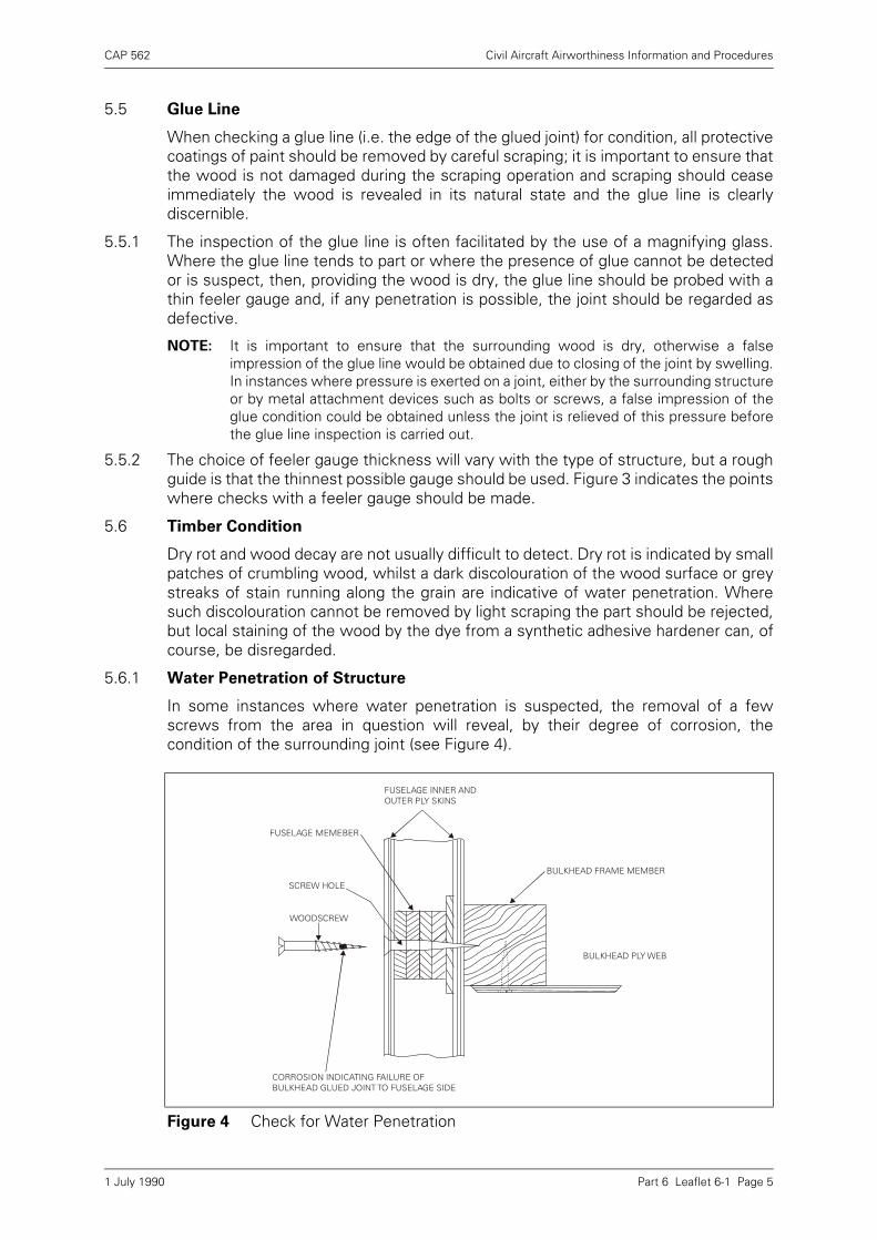
5.6.1 Water Penetration of Structure
In some instances where water penetration is suspected, the removal of a fewscrews from the area in question will reveal, by their degree of corrosion, thecondition of the surrounding joint (see Figure 4).
Figure 4 Check for Water Penetration
FUSELAGE INNER AND OUTER PLY SKINS
BULKHEAD FRAME MEMBER
BULKHEAD PLY WEB
FUSELAGE MEMEBER
SCREW HOLE
WOODSCREW
CORROSION INDICATING FAILURE OF BULKHEAD GLUED JOINT TO FUSELAGE SIDE
1 July 1990
CAP 562 Civil Aircraft Airworthiness Information and Procedures
Part 6 Leaflet 6-1 Page 6
a) Slight corrosion of the screw due to the adhesive will occur following the originalmanufacture, therefore, the condition of the screw should be compared with thatof a similar screw, removed from another part of the structure known to be freefrom water soakage.
NOTE: Plain brass screws are normally used for reinforcing glued wooden members,although zinc coated brass is sometimes used. Where hard woods such asmahogany or ash are concerned, steel screws are sometimes used. Unlessotherwise specified by the aircraft manufacturer, it is usual to replace screws withnew screws of identical length but one size larger.
b) Another means of ascertaining if water penetration has taken place is to removethe bolts holding fittings at spar root-end joints, aileron hinge brackets, etc. (seeFigure 3). Primary joints may have bushed holes and the bushes should also bewithdrawn. Corrosion on the surface of these bolts and bushes and timberdiscolouration, will provide a useful indication of any water penetration which hastaken place. Bolts and bushes should be smeared with an approved protectivetreatment before being refitted through wooden members.
NOTE: When refitting bolts it is important to ensure that the same number of shrinkagewashers are fitted as were fitted originally.
c) Experience of a particular aircraft will indicate those portions of the structure mostprone to water penetration and moisture entrapment (e.g. at window rails or thebottom lower structure of entry doors), but it must be borne in mind that this is notnecessarily indicative of the condition of the complete aircraft.
d) Where drain holes have become blocked, water soakage will invariably be found.Drain holes should be cleared during routine maintenance.
5.6.2 Water Penetration of Top Surfaces
As indicated in paragraph 3.2.3, the condition of the proofed-fabric covering on plysurfaces is of great importance. If any doubt exists regarding its proofing qualities orif there are any signs of poor adhesion, cracks, or other damage, it should be peeledback to reveal the ply skin.
a) The condition of the exposed ply surface should be examined and if waterpenetration has occurred, this will be shown by dark grey streaks along the grainand a dark discolouration at ply joints or screw countersunk holes, together withpatches of discolouration. If these marks cannot be removed by light scraping or,in the case of advanced deterioration, where there are small surface cracks orseparation of the ply laminations, then the ply should be rejected. Where evidenceof water penetration is found, sufficient of the surfaces should be stripped todetermine its extent.
b) Providing good care is taken of the protective covering from the beginning, muchdeterioration can be avoided.
5.6.3 Miscellaneous Defects
During the inspection of the aircraft, the structure should be examined for otherdefects of a more mechanical nature. Guidance on such defects is given in thefollowing paragraphs.
a) Shrinkage. Shrinkage of timber, as well as inducing stresses in glued joints, cancause looseness of metal fittings or bolts and, if fluctuating loads are present, canresult in damage to the wood fibres at the edges of the fittings or around the boltholes. Shrinkage can be detected by removing any paint or varnish as described inparagraph 5.5 and attempting to insert a thin feeler gauge between the timber andthe fitting or bolt head.
1 July 1990
CAP 562 Civil Aircraft Airworthiness Information and Procedures
Part 6 Leaflet 6-1 Page 7
b) Elongated Bolt Holes. Where bolts secure fittings which take load-carryingmembers, or where the bolts are subject to landing or shear loads, the bolt holesshould be examined for elongation or surface crushing of the wood fibres. Thebolts should be removed to facilitate the examination and, in some cases, the boltitself may be found to be strained. Rectification of elongated bolt holes must becarried out in accordance with the approved Repair Manual, the usual methodbeing to open out the holes and fit steel bushes.
c) Bruising and Crushing. A check should be made for evidence of damage suchas bruises or crushing of structural members, which can be caused, for example,by overtightening bolts. Repair schemes for such damage are governed by theextent and depth of the defect.
d) Compression Failures. Compression failures, sometimes referred to ascompression 'shakes', are due to rupture across the wood fibres. This is a seriousdefect which at times is difficult to detect and special care is necessary wheninspecting any wooden member which has been subjected to the abnormalbending or compression loads which may occur during a heavy landing. In the caseof a member having been subjected to an excessive bending load, the failure willappear on the surface which has been compressed, usually at a position ofconcentrated stress such as at the end of a hardwood packing block; the surfacesubjected to tension will normally show no defects. In the case of a member takingan excessive direct compression load, the failure will usually be apparent on allsurfaces. Where a compression failure is suspected, a hand torch shone along themember, with the beam of light running parallel to the grain, will assist in revealingthis type of failure.
e) Previous Repairs. When examining a structure for signs of the defectsmentioned above, particular attention should be paid to the integrity of repairswhich may have been carried out previously.
6 Joint Failure
A glued joint may fail in service as a result of an accident or due to excessivemechanical loads having been imposed upon it, either in tension or in shear. It is oftendifficult to decide the nature of the load which caused the failure, but it should beborne in mind that glued joints are generally designed to take shear loads.
6.1 If a joint is designed to take tension loads, it will be secured by a number of bolts orscrews (or both) fairly closely pitched in the area of tension loading. If a failure occursin this area, it is usually very difficult to form an opinion of the actual reasons for it,due to the considerable break-up of the timber occurring in close proximity with thebolts.
6.2 In all cases of glued joint failure, whatever the direction of loading, there should be afine layer of wood fibres adhering to the glue, whether or not the glue has come awaycompletely from one section of the wood member. If there is no evidence of fibreadhesion, this may indicate glue deterioration, but if the imprint of wood grain isvisible in the glue this is generally due to 'case hardening' of the glue duringmanufacture of the joint and the joint has always been below strength. If the glueexhibits a certain amount of crazing or star shaped patterns, this indicates too rapidsetting, or the pot life of the glue having been exceeded. In these cases, the otherglued joints in the aircraft should be considered suspect.
NOTE: The use of a magnifying glass will facilitate the above inspections.
1 July 1990
CAP 562 Civil Aircraft Airworthiness Information and Procedures
Part 6 Leaflet 6-1 Page 8
6.3 Damage caused by a heavy landing may be found some distance away from thelanding gear attachment points. Secondary damage can be introduced bytransmission of shock from one end of a strut or bracing to its opposite end, causingdamage well away from the point of impact. A thorough inspection of the existingpaint or varnish at suspected primary or secondary impact points may reveal, bycracks or flaking, whether damage has actually occurred.
1 July 1990
CAP 562 Civil Aircraft Airworthiness Information and Procedures
Part 6 Leaflet 6-2 Page 1
Leaflet 6-2 Inspection of Metal Aircraft Structures
1 Introduction
This Leaflet gives general guidance on the inspection of those parts of a metal aircraftstructure which, because of their remoteness, complexity or boxed-in design, are notreadily accessible for routine maintenance or require special attention in the light ofoperational experience.
2 General
Deterioration may arise from various causes and can affect various parts of thestructure according to the design of the aircraft and the uses to which it is put.Therefore, this Leaflet should be read in conjunction with the appropriatemanufacturer’s publications and the Maintenance Schedule for the aircraftconcerned.
2.1 Although considerable guidance may be given in the appropriate publications as tosuitable opportunities for inspecting normally inaccessible structures (e.g. when awing tip is removed permitting access to the adjacent wing structure) experienceshould indicate to the operator further opportunities for such inspections which canbe included in the Maintenance Schedule. Apart from the airworthiness aspects,these combined inspections could often be to the operator’s advantage, since theywould obviate the need for future dismantling.
2.2 Where access has been gained to a part of the structure which is normallyinaccessible, advantage should be taken of this dismantling to inspect all parts ofsystems thus exposed.
3 Corrosion
The presence of corrosion in aircraft structures is liable to result in conditions whichmay lead to catastrophic failures. It is therefore essential that any corrosive attack isdetected and rectified in the earliest stages of its development.
3.1 In general, no corrosive attack on an aircraft structure will occur without the presenceof water in some form. However, a fact less well appreciated is that, in a wide varietyof ambient conditions, condensation will form on various parts of the structure andthis is one of the main causes of corrosion.
3.1.1 By the nature of their operation, aircraft are exposed to frequent changes ofatmospheric temperature and pressure and to varying conditions of relative humidity;therefore, all parts of the structure are subject to some form of condensation. Theresultant water takes into solution a number of corrosive agents from the atmosphereor from spillages (which convert the water into a weak acid) and will corrode mostmetal surfaces where the protective treatment has been damaged or is inadequate.Cases of serious corrosion have been found in both closed and exposed parts ofstructures of aircraft operated under a wide variety of conditions.
3.1.2 Corrosion can be intergranular; therefore, the removal of the surface products ofcorrosion followed by reprotection is not necessarily effective. Once the surface ispenetrated the reduction in strength due to corrosion is disproportionate to thereduction in thickness of the metal.
1 July 1990

CAP 562 Civil Aircraft Airworthiness Information and Procedures
Part 6 Leaflet 6-2 Page 2
3.2 Air-conditioned Compartments
In air-conditioned compartments, condensation will occur where the warm inside airimpinges on the colder areas of the structure such as the inner surfaces of a pressurecabin skin. Considerable quantities of water will tend to collect and run down theinside of the cabin walls.
3.2.1 To avoid corrosion it is important to ensure that the water is unimpeded in its flowdown to the bilge area. The structure and all drain holes through stringers, etc., shouldbe kept clean and free from obstructions and drainage ducts should be checked forclearance and damage. A check should be made to ensure that water or moisture isnot being trapped by the thermal acoustic lining or any other form of upholstery.
3.2.2 Water collecting in the lower parts of the structure and in the bilge area can be highlycontaminated. It will not only contain the corrosive agents mentioned in paragraph3.1.1, but also other impurities due to fumes, spillages, etc., emanating from thegalley, toilets and smoking compartments, thus intensifying the corrosive nature ofthe water. At specified periods these parts of the structure should be thoroughlycleaned and carefully inspected for signs of corrosion and for deterioration of theprotective treatment.
3.2.3 Thermal acoustic linings usually have a waterproof covering on the side adjacent tothe structure, or the thermal acoustic material may be completely enveloped in awaterproof covering. Any damage to the waterproof covering may lead toconsiderable absorption of water into the lining, setting up corrosion between thedamaged lining and the surrounding structure.
NOTE: Water soakage of upholstery and especially of thermal acoustic linings can alsoresult in an appreciable increase in aircraft weight. Instances have also occurredwhere saturated compartment linings have caused electrical failures.
3.3 Structural Parts Susceptible to Corrosion
The manufacturer’s publications give general guidance on the inspection of thoseparts of the structure which are most likely to be attacked by corrosion. Nevertheless,it should be noted that, in the light of operational experience, other parts of thestructure may require special attention. Engineers should be on the alert for any signsof corrosion in parts of the structure not specifically mentioned in the manufacturer’spublications or instructions.
3.3.1 In 'blind' or boxed-in structures where accessibility is difficult and where cleaning andmaintenance are awkward, dirt and dust tend to collect and lodge in various parts.This dirt and dust acts as a 'wick' for moisture which, in the course of time, will workthrough any inadequate protective treatment and penetrate to the metal to act as anelectrolyte. Even on new aircraft the problem is still present in some boxed-in orintricate structures.
NOTE: Protective treatments with a rough surface finish, such as primer paints, tend to holddust and dirt and cleaning is rendered more difficult because of this tendency of dustand dirt to adhere to such surfaces. Hard gloss finishes, such as epoxy resin paints,will provide a more effective and lasting protection.
3.3.2 Completely boxed-in structures should be adequately vented to prevent stagnation ofthe internal air. It is important to ensure that vents and drain holes are clear, are of thecorrect size and are unobstructed by ice in freezing conditions on the ground.
3.3.3 Honeycomb structures, especially those in components of small cross-sectional area(e.g. wing flaps), are often prone to the collection of water if careful attention has notbeen given to the sealing around attachment screw holes and at skin joints to preventingress of moisture. Cases are known where the trapped water in the structure has
1 July 1990

CAP 562 Civil Aircraft Airworthiness Information and Procedures
Part 6 Leaflet 6-2 Page 3
frozen and caused distortion of the outer skin of the component due to internalexpansion.
3.3.4 Fuselage keel areas, structures concealed by upholstery (see e.g. paragraph 3.2) andthe double skin of freight bay floors, are typical areas liable to corrosion. Specialattention should be given to all faying surfaces in these areas and particularly thefaying surfaces of stringers to skin panels and skin lap joints. In general, visualinspection supplemented by radiological methods of examination is a satisfactoryway of detecting corrosion, provided it is expertly carried out and proper correlationbetween the findings of each method is maintained. In some instances, however,normal methods of visual inspection supplemented by radiological examination havenot proved satisfactory and dismantling of parts of the structure may be required toverify the condition of the faying surfaces.
3.3.5 Structures manufactured from light gauge materials which are spot-welded together,such as the faying surfaces of stringers mentioned in the previous paragraph, areliable to serious and rapid corrosion as this method of attachment precludes thenormal anti-corrosive treatments (e.g. jointing compound) at the faying surfaces.Cases of serious corrosion have also been found in similar structures riveted togetherwhere the jointing compound has been found to be inadequate.
3.3.6 In some instances, where stringers are of top-hat section and are bonded to the panelby a thermosetting adhesive, corrosion has been known to affect the stringers, thepanel and the bonding medium; such stringers are often sealed at their ends toprevent the ingress of moisture, etc. Where adhesive is used to attach a doubler to askin, corrosion can occur between the surfaces and will eventually be indicated by aquilted appearance.
3.4 Exhaust Gases
Structural parts which are exposed to exhaust gases are prone to corrosion due to thesulphur content of exhaust gases and jet efflux. Although this problem can bereduced by regular and thorough cleaning, particular attention should be given to thecondition of the protective treatment of these structures.
3.5 Stress Corrosion
3.5.1 Stress corrosion in aluminium tends to occur mainly in the high-strength alloys and isdue to locked-in stresses resulting from some aspects of heat treatment orinappropriate assembly practices. Stress corrosion takes the form of cracking which,in conjunction with other corrosion, can lead to the sudden and complete failure ofstructural parts.
3.5.2 Stress corrosion cracking in titanium depends on the composition of the alloy, itsprocessing and its notch sensitivity. Some titanium alloys may develop rapid crackgrowth if contaminated with a saline solution after a crack has been initiated.
3.6 Fretting
Fatigue failures often result from fretting at structural bolted joints. Fretting isrevealed by black or greyish brown powder or paste around the periphery of the fayingsurfaces and may result in the formation of cracks at the outer edge of the frettedarea; these cracks may develop across the component and will not necessarily passthrough the bolt hole. Dismantling of suspect parts is usually necessary and aninspection by penetrant dye, magnifying lens, eddy current or ultrasonic (surfacewave) methods should be carried out.
1 July 1990

CAP 562 Civil Aircraft Airworthiness Information and Procedures
Part 6 Leaflet 6-2 Page 4
4 Spillage
Spillage or system leaks of extraneous fluids which may penetrate the structureduring maintenance, repair or operation of the aircraft, should be carefully traced andthoroughly cleaned out. Where required, any protective treatment should be restored.Fluids such as ester-based engine oils, glycol defrosting fluids, etc., will damage mostprotective treatments not intended to be in contact with them. Accidental spillage ofrefreshments such as mineral waters, coffee, etc., have a particularly deleteriouseffect on floor structures.
4.1 With an aircraft in operation there are areas where spillages invariably occur, such asin galleys and toilet compartments. Here, careful cleaning and the maintenance of anyspecial floor protection is important. The floor structures around and below thesecompartments should receive special attention to ensure protection against seepageand corrosion. Where animals are carried, special precautions are essential becausecorrosion due to animal fluid can cause rapid deterioration of metals. The floor andsides of compartments in which animals are housed should be protected by suitablemeans against seepage and the structure below the floor should be carefullyinspected for any signs of seepage or corrosion.
NOTE: Where animals are not housed in containers specially designed for air transport,unbroken impervious sheeting such as waterproof canvas or heavy polythene sheet,should be laid on the floor and fixed at the required height on the fuselage sides andbulkheads to prevent any seepage into the aircraft structure. A form of matting,preferably made of absorbent material, should be laid on the sheeting to preventdamage due to animal movements.
4.2 Battery compartments should be examined for any signs of acid corrosion.Compartment vents should be clean and undamaged and the anti-sulphuric protectivetreatment should be carefully maintained. Special attention should be given to thestructure in the immediate vicinity of the battery for any signs of corrosion caused byacid spillage or a damaged battery. It should be noted that heavy concentrations ofbattery fumes, resulting from faulty compartment venting or a runaway battery, mayalso lead to corrosion in the surrounding structure.
NOTE: If there is any indication of corrosion, the parts affected should be cleaned with asolution of water and washing soda, then rinsed with fresh water and dried out. After24 hours a re-check should be made for further signs of corrosion and, if satisfactory,the protective treatment should be restored.
4.3 The spillage of mercury in an aircraft can have devastating effects on any aluminiumalloy skin or structure with which it comes into contact.
5 Corrosive Effects of Agricultural Chemicals
On aircraft used for crop spraying or dusting, considerable attention and special careshould be given to the inspection of the structure owing to the highly corrosive natureof certain of the chemicals used for these purposes. The corrosive effect of some ofthe chemicals used for agricultural purposes may not always be fully known. Somechemicals which were considered to be harmless to aircraft materials, have proved,in the course of time, to be corrosive.
5.1 Thorough cleaning of the whole aircraft structure after agricultural spraying operationsis very important. Unless otherwise specified by the manufacturer of the chemical,the aircraft should be thoroughly washed, both internally and externally, with copioussupplies of clean water. Engine intakes and exhausts and other openings, should beblanked during the washing to prevent the ingress of water. After washing, it is
1 July 1990

CAP 562 Civil Aircraft Airworthiness Information and Procedures
Part 6 Leaflet 6-2 Page 5
essential to check that no pockets of chemicals or water remain trapped in thestructure, that all drains are clear and that all covers or devices used to prevent theingress of chemicals are properly refitted.
5.2 A check should be made to ensure that the spray equipment tanks, pipes, pumps,etc., are leak-proof and that spray booms or spray nozzles are in their correctpositions.
5.3 When filling up with chemical spray fluids care is necessary to avoid spillage. Wherethere is no provision to prevent spilled fluid finding its way into the structure, it isessential to avoid over-filling and the chance of accidental spillage can be reduced byusing the proper filling equipment. If spillage does occur, it should be cleaned outimmediately before it has penetrated into parts of the structure where cleaning wouldbe more difficult.
6 Metal Fatigue
Metal fatigue can be briefly described as a weakening of a metal part under repeatedapplications of a cycle of stress. The weakening effect can be seriously acceleratedby corrosion of the metal.
6.1 In the early stages, fatigue damage is difficult to detect by visual inspection and oneof the methods of non-destructive examination outlined in the Part 4 series of Leaflets(see also paragraph 9) is usually specified; the method used depending on the type ofstructure and material concerned. In the majority of cases the presence of fatiguedamage is revealed by the formation of a small hairline crack or cracks.
6.2 Those parts of a structure where fatigue damage may occur are determined by designcalculations and tests based on the expected operational use of the aircraft andsubstantiated by operational experience. At the periods specified in the appropriatepublications, examination or renewal of the parts will be required. These periods areusually in terms of flying time or the number of landings, or from readings logged byload recording instruments. With certain materials and structures, renewal orsampling checks may be required on a calendar basis.
6.3 It is important to note that some parts of a structure may be liable to fatigue damageresulting from unforeseen causes, e.g. parts damaged or strained on assembly,invisible damage to the structure during assembly or maintenance work, or fretting(see Leaflet 6–7). When carrying out inspections it is important to check carefully forany signs of cracks emanating from points of stress concentration such as bolt-holes,rivets, sharp changes in section, notches, dents, sharp corners, etc. Fatigue damagecan also be caused by pits and notches created by corrosion, although the corrosionmay no longer be active. During the application of repeated stress cycles, crevicescan be opened up and may eventually result in a fatigue failure.
NOTE: Poor fitting or malassembly can reduce fatigue life considerably. A spar has beenknown to fail under tests at a fraction of its normal life as a result of the stressconcentration caused by a tool mark in a bolt-hole. Defects such as a burr on a boltcan cause a scratch inside the bolt-hole, which can seriously accelerate fatiguedamage in a stressed member.
7 Cleanliness
It is important that aircraft should be thoroughly cleaned periodically and referenceshould be made to Leaflet 2–6.
1 July 1990

CAP 562 Civil Aircraft Airworthiness Information and Procedures
Part 6 Leaflet 6-2 Page 6
7.1 Care should be taken not to damage protective treatments when using scrubbingbrushes or scrapers and any cleaning fluids used should have been approved by theaircraft manufacturer. For final cleaning of a boxed-in type of structure an efficientvacuum cleaner, provided with rubber-protected adaptors to prevent damage, shouldbe used. The use of air jets should be avoided as this may lead to dirt, the productsof corrosion, or loose articles, being blown from one part of the structure to another.
8 Inspection
The structure should be maintained in a clean condition and a careful check should bemade for any signs of dust, dirt or any extraneous matter, especially in the moreremote or 'blind' parts of the structure. Loose articles such as rivets, metal particles,etc., trapped during manufacture or repair, may be found after the aircraft has beenin operation for some considerable time. It is important to examine these loosearticles to ensure that they did not result from damaged structure. It is generally easyto determine if a loose article has formed part of the structure by its condition, e.g. anunformed rivet could be considered as a loose article, but a rivet which had beenformed would be indicative of a failure.
8.1 General
8.1.1 The structure should be examined for any signs of distortion or movement betweenits different parts at their attachment points, for loose or sheared fasteners (whichmay sometimes remain in position) and for signs of rubbing or wear in the vicinity ofmoving parts, flexible pipes, etc.
8.1.2 The protective treatment should be examined for condition. On light alloys a checkshould be made for any traces of corrosion, marked discolouration or a scaly, blisteredor cracked appearance. If any of these conditions is apparent the protective treatmentin the area concerned should be carefully removed and the bare metal examined forany traces of corrosion or cracks. If the metal is found satisfactory, the protectivetreatment should be restored.
NOTE: To assist in the protection of structures against corrosion some manufacturers mayattach calcium chromate and/or strontium chromate sachets to the vulnerable partsof the structure. The presence of chromate in the sachets can be checked by feelduring inspection. After handling these materials, the special precautions, e.g. handwashing, given in the manufacturer’s manual, should be followed.
8.1.3 In most cases where corrosion is detected in its early stages, corrective treatmentwill permit the continued use of the part concerned. However, where the strength ofthe part may have been reduced beyond the design value, repair or replacement maybe necessary. Where doubt exists regarding the permissible extent of corrosion, themanufacturer should be consulted.
8.1.4 The edges of faying surfaces should receive special attention (see alsoparagraph 3.3.4); careful probing of the joint edge with a pointed instrument mayreveal the products of corrosion which are concealed by paint. In some instancesslight undulations or bumps between the rivets or spot welds, or quilting in areas of
NOTES: 1) A wing structure has been known to have had a rib sheared at its sparattachments due to the accidental application of an excessive load, without anyexternal evidence of damage, because the skin returned to its original contourafter removal of the load.
2) For the inspection of bolted joints see Leaflet 6–7.
1 July 1990

CAP 562 Civil Aircraft Airworthiness Information and Procedures
Part 6 Leaflet 6-2 Page 7
double skins due to pressure from the products of corrosion, will indicate an advancedstate of deterioration. In some cases this condition can be seen by an examination ofthe external surface, but as previously mentioned in this Leaflet, dismantling of partsof the structure to verify the condition of the joints may be required.
8.2 Visual Examination
Nearly all the inspection operations on aircraft structures are carried out visually and,because of the complexity of many structures, special visual aids are necessary toenable such inspections to be made. Visual aids vary from the familiar torch andmirrors to complex instruments based on optical principles and, provided the correctinstrument is used, it is possible to examine almost any part of the structure.
NOTE: Airworthiness Requirements normally prescribe that adequate means shall beprovided to permit the examination and maintenance of such parts of the aeroplaneas require periodic inspection.
8.2.1 Light Probes
It is obvious that good lighting is essential for all visual examinations and special lightprobes are often used.
a) For small boxed-in structures or the interior of hollow parts such as the bores oftubes, special light probes, fitted with miniature lamps, as shown in Figure 1, areneeded. Current is supplied to the lamp through the stem of the probe from abattery housed in the handle of the probe. These small probes are made in a largevariety of dimensions, from 5 mm (3/16 in) diameter with stem lengths from 50 mm(2 in) upwards.
b) Probes are often fitted with a magnifying lens and attachments for fitting an angledmirror. Such accessories as a recovery hook and a recovery magnet may also formpart of the equipment.
NOTES: 1) To avoid damage to the structure, the probing of a joint with a pointedinstrument should be carried out with discretion by an experienced person.Any damage done to the protective paint coating, however small, should bemade good.
2) Where dismantling of parts of the structure is required, reference should bemade to Leaflet 6–4.
Figure 1 Typical Light Probe
1 July 1990
CAP 562 Civil Aircraft Airworthiness Information and Procedures
Part 6 Leaflet 6-2 Page 8
c) For the larger type of structure, but where the design does not permit the use ofmains-powered inspection lamps, it is usually necessary to use a more powerfullight probe. This type of light probe consists of a lamp (typically an 18 watt, 24 volttype) which is protected by a stiff wire cage and mounted at one end of a semi-flexible tube or stem. On the other end is a handle with a light switch and electricalconnections for coupling to a battery supply or mains transformer. As the diameterof the light probe is quite small it can be introduced through suitable apertures tothe part of the structure to be inspected.
NOTE: Where spillage or leakage of flammable fluids may have occurred or wheninspecting fuel tanks, etc., it is important to ensure that the lighting equipment usedis flameproof, e.g. to BS 229.
8.2.2 Inspection Mirrors
Probably the most familiar aid to the inspection of aircraft structures is a small mirrormounted at one end of a rod or stem, the other end forming a handle. Such a mirrorshould be mounted by means of a universal joint so that it can be positioned at variousangles thus enabling a full view to be obtained behind flanges, brackets, etc.
a) A useful refinement of this type of mirror is where the angle can be adjusted byremote means, e.g. control of the mirror angle by a rack and pinion mechanisminside the stem, with the operating knob by the side of the handle, thus permittinga range of angles to be obtained after insertion of the instrument into the structure.
b) Mirrors are also made with their own source of light mounted in a shroud on thestem and are designed so as to avoid dazzle. These instruments are often of themagnifying type, the magnification most commonly used being 2X.
8.2.3 Magnifying Glasses
The magnifying glass is a most useful instrument for removing uncertainty regardinga suspected defect revealed by eye, for example, where there is doubt regarding thepresence of a crack or corrosion. Instruments vary in design from the small simplepocket type to the stereoscopic type with a magnification of 20X. For viewing insidestructures, a hand instrument with 8X magnification and its own light source is oftenused.
a) Magnification of more than 8X should not be used unless specified. A too powerfulmagnification will result in concentrated viewing of a particular spot and will notreveal the surrounding area. Magnification of more than 8X may be used, however,to re-examine a suspected defect which has been revealed by a lowermagnification.
b) When using any form of magnifier it is most important to ensure that the surfaceto be examined is sufficiently illuminated.
8.2.4 Endoscopes (Leaflet 4–9)
An endoscope (also known as an introscope, boroscope or fibrescope, depending onthe type and the manufacturer) is an optical instrument used for the inspection of theinterior of structure or components. Turbine engines, in particular, are often designedwith plugs at suitable locations in the casings, which can be removed to permitinsertion of an endoscope and examination of the interior parts of the engine. Inaddition, some endoscopes are so designed that photographs can be taken of thearea under inspection, by attaching a camera to the eyepiece; this is useful forcomparison and record purposes.
a) One type of endoscope comprises an optical system in the form of lenses andprisms, fitted in a rigid metal tube. At one end of the tube is an eyepiece, usually
1 July 1990

CAP 562 Civil Aircraft Airworthiness Information and Procedures
Part 6 Leaflet 6-2 Page 9
with a focal adjustment and at the other end is the objective head containing alamp and a prism. Depending on the design and purpose of the instrument avariety of objective heads can be used to permit viewing in different directions. Theelectrical supply for the lamp is connected near the eyepiece and is normallysupplied from a battery or mains transformer.
i) These instruments are available in a variety of diameters from approximately6 mm (¼in) and are often made in sections which can be joined to make any lengthrequired. Right-angled instruments based on the periscope principle are alsoavailable for use where the observer cannot be in direct line with the part to beexamined.
b) A second type of endoscope uses 'cold light', that is, light provided by a remotelight source box and transmitted through a flexible fibre light guide cable to theeyepiece and thence through a fibre bundle surrounding the optical system to theobjective head. This type provides bright illumination to the inspection area,without the danger of heat or electrical sparking and is particularly useful insensitive or hazardous areas.
c) A third type of endoscope uses a flexible fibre optical system, thus enablinginspection of areas which are not in line with the access point.
9 Non-destructive Examination
In cases where examination by visual means is not practicable or has left someuncertainty regarding a suspect part, the use of one of the methods of non-destructive examination will normally determine the condition of the part.
9.1 A brief outline of the methods of non-destructive examination most commonly usedon aircraft structures is given in the following paragraphs. For further information onthese and other methods reference should be made to the Part 4 series of Leaflets.The selection of the method to be used will depend largely on the design of thestructure, its accessibility and the nature of the suspected defect.
9.2 Penetrant Dye Processes (Leaflet 4–2 and 4–4)
These processes are used mainly for checking areas for those defects which breakthe surface of the material, which may be too small for visual detection by 2Xmagnification and where checking at higher magnifications would be impractical.Basically, the process consists of applying a red penetrant dye to the bare surfaceunder test, removing after a predetermined time any excess dye and then applying adeveloper fluid containing a white absorbent. Any dye which has penetrated into adefect (e.g. crack) is drawn to the surface by the developer and the resultant stain willindicate the presence and position of the defect.
NOTE: Penetrant dye processes of inspection for the detection of surface defects requireno elaborate equipment or specialised personnel. It is emphasised that thecleanliness of the surface to be tested is of prime importance if this process is toreveal microscopic cracks.
9.2.1 The manufacturer’s detailed instructions regarding the applications of the processshould be carefully followed. The most suitable processes for testing parts of aircraftstructures 'in situ' are those which employ water-washable dye penetrants, with thepenetrant and developer contained in aerosol packs.
9.2.2 The characteristics of the red marks, such as the rapidity with which they develop andtheir final size and shape, provide an indication as to the nature of the defect revealed.
1 July 1990

CAP 562 Civil Aircraft Airworthiness Information and Procedures
Part 6 Leaflet 6-2 Page 10
9.2.3 After test, the developers should be removed by the method prescribed by theprocess manufacturer and the protective treatment should be restored.
NOTE: A similar process to the Penetrant Dye Process is the Fluorescent PenetrantProcess. However, this process is less adaptable for testing aircraft parts 'in situ'because portable 'black light' lamps are used to view the parts and dark roomconditions are generally required.
9.3 Radiographic Examination (Leaflet 4–6)
The use of radiography will often facilitate the examination of aircraft structures andit is used for the detection of defects in areas which cannot be examined by othermeans because of inaccessibility or the type of defect.
9.3.1 Radiography can be a valuable aid to visual inspection and the examination of certainparts of an aircraft structure by an X-ray process will often result in a morecomprehensive inspection than would otherwise be possible. However, radiographicmethods can be both unsatisfactory and uneconomical unless great care is taken inthe selection of suitable subjects. In this respect the opinion of the aircraftmanufacturer should be sought.
9.3.2 During routine inspections, the use of radiography based on reliable techniques ofexamination can result in more efficient and rapid detection of defects. In someinstances, defects such as cracking, loosening of rivets, distortion of parts and seriouscorrosion of the pitting type can be detected by this method. It should be borne inmind, however, that a negative result given by a general NDT method such asradiography is no guarantee that the part is free from all defects.
9.3.3 Where radiography is used for the detection of surface corrosion it is recommendedthat selected areas should be radiographed at suitable intervals, each time simulatingthe original radiographic conditions, so that the presence of corrosion will becomeapparent by a local change in the density of succeeding radiographs.
9.3.4 The accurate interpretation of the radiographs is a matter which requires considerableskill and experience if the maximum benefits are to be obtained. It is essential thatthe persons responsible for preparing the technique and viewing the results have anintimate knowledge of the structure.
NOTE: Close contact should be maintained with the aircraft manufacturer who will beaware of problem areas on an aircraft and be able to advise on particular inspectiontechniques.
9.4 Ultrasonic Examination (Leaflet 4–5)
In some instances ultra-sonic examination is the only satisfactory method of testingfor certain forms of defects. Ultrasonic flaw detectors can be used to check certainaircraft parts 'in situ' and it is sometimes an advantage to use this method to avoidextensive dismantling which would be necessary in order to use some other method.The chief value of ultrasonic examination in such circumstances is that cracks onsurfaces which are not accessible to visual examination should be revealed. Thussolid extrusions, forgings and castings which are backed by skin panels, but whichhave one suitably exposed smooth surface, can be tested for flaws on their interfacesurface without breaking down the interface joint. On some aircraft, spar booms andsimilar extruded members require periodic examination for fatigue cracks, but theareas of suspected weakness may be inaccessible for examination by the penetrantdye method. In such cases radiography may be recommended, but where ultrasonictesting can be used it will give quicker results on those parts which lend themselvesto this form of testing and may also be useful to confirm radiographic evidence.
1 July 1990
CAP 562 Civil Aircraft Airworthiness Information and Procedures
Part 6 Leaflet 6-2 Page 11
9.5 Eddy Current Examination (Leaflet 4–8)
Eddy current methods can detect a large number of physical and chemical changesin a conducting material and equipment is designed specifically to perform particulartypes of test, e.g. flaw detection, conductivity measurement and thicknessmeasurement.
9.5.1 The main advantages of this method of inspection are that it does not requireextensive preparation of the surface or dismantling of the part to be tested and doesnot interfere with other work being carried out on an aircraft. In addition, small,portable, battery-operated test sets can be used in comparatively inaccessible partsof the structure.
9.5.2 Eddy current testing is usually of the comparative type, indications from a referencepiece or standard being compared with indications from the part under test. Atechnique for detecting a particular fault is established after trials have indicated amethod which gives consistent results.
9.6 Magnetic Flaw Detection (Leaflet 4–7)
Magnetic flaw detection methods are seldom used on aircraft structures and aregenerally restricted to the manufacturing, fabrication and inspection of parts. Themethod has, however, sometimes been used where other non-destructive testingmethods have proved to be unsatisfactory. Before using the method, the effects ofmagnetisation on adjacent structure, compasses and electronic equipment should beconsidered and it should be ensured that the magnetic ink or powder can besatisfactorily removed. If this method is used, demagnetisation and a test for remnantmagnetism must be carried out to ensure that there will be no interference with theaircraft avionic systems and magnetic compasses.
1 July 1990

INTENTIONALLY LEFT BLANK
CAP 562 Civil Aircraft Airworthiness Information and Procedures
Part 6 Leaflet 6-3 Page 1
Leaflet 6-3 Inspection of Metal Aircraft After Abnormal
Occurrences
1 Introduction
1.1 Aircraft are designed to withstand flight and landing loads within specified limits;these limits are calculated to allow for all normal manoeuvres and exercises whichmay be undertaken by that aircraft and include safety factors to allow for unforeseencircumstances. If design limits are exceeded due to abnormal occurrences, theintegrity of the structure may be jeopardised and safety impaired. Any report orevidence on the aircraft which suggests that the design limits have been exceededor equipment damaged should, therefore, be followed by a careful inspectionappropriate to the nature of the occurrence and in accordance with the ApprovedMaintenance Manual.
1.2 The types of occurrence which may lead to structural damage are considered in thefollowing paragraphs, but these should be considered as a general guide and not as acomplete list; additional inspections may be required on some aircraft and these willbe described in the appropriate manuals. Inspections peculiar to helicopters aredescribed in paragraph 8 of this leaflet and some guidance on the inspection ofwooden aircraft structures is given in Leaflet 6–1.
1.3 General
The appropriate aircraft Maintenance Manual and other relevant literature, such asService Bulletins, should be consulted to ascertain the particular inspections whichare necessary and the areas where damage has been known to occur in similarcircumstances on aircraft of the same type. The aircraft should then be viewed forobvious damage such as distortion or twisting of the main structure, before carryingout the detailed inspections applicable to the particular incident.
1.4 The repairs necessary, if damage is found during inspection, are outside the scope ofthis Leaflet and reference should be made to Leaflet 6–4 and to the manufacturer’sOverhaul and Repair Manuals.
1.5 The subject headings are as follows:
Paragraph Subject Page
1 Introduction 1
2 Heavy or Overweight Landings 2
3 Burst Tyre Incidents 4
4 Tyre Explosion 5
5 Flight Through Severe Turbulence 5
6 Lightning Strikes 6
7 Damage from Jet Blast 7
8 Helicopters 7
9 Other Occurrences 8
1 July 1990
CAP 562 Civil Aircraft Airworthiness Information and Procedures
Part 6 Leaflet 6-3 Page 2
1.6 Related CAAIP Leaflets:
2 Heavy or Overweight Landings
2.1 An aircraft landing gear is designed to withstand landing at a particular aircraft weightand vertical descent velocity. If either of these parameters is exceeded during alanding, then it is probable that some damage may be caused to the landing gear orits supporting structure. Overstressing may also be caused by landing with drift orlanding in an abnormal attitude, e.g. nose or tail wheel striking the runway before themain wheels.
2.2 Some aircraft are fitted with heavy landing indicators, which give a visual indicationthat specified 'g' forces have been exceeded, but in all cases of suspected heavylandings, the flight crew should be consulted for details of aircraft weight, fueldistribution, landing conditions and whether any noises indicative of structural failurewere heard.
2.3 The damage which may be expected following a heavy landing would normally beconcentrated around the landing gear, its supporting structure in the wings orfuselage, the wing and tailplane attachments and the engine mountings. Secondarydamage may be found on the fuselage upper and lower skin and structure and wingskin and structure, depending on the configuration and loading of the aircraft. Onsome aircraft it is specified that, if no damage is found in the primary areas, thesecondary areas need not be inspected; but if damage is found in the primary areas,then the inspection must be continued.
2.4 Because of the number of factors involved, it is not possible to lay down precisedetails of the inspections which must be made after any incident, on any type ofaircraft, but a preliminary inspection should normally include the items detailed inparagraphs 2.5 to 2.10.
2.5 Landing Gear
a) Examine tyres for excessive creep, flats, bulges, cuts, pressure loss, excessivegrowth and security of balance weights/patches.
b) Examine wheels and brakes for cracks, other damage and fluid leaks.
c) Examine axles, struts and stays for distortion and other damage.
d) Check shock struts for fluid leaks, scoring and abnormal extension.
e) Examine landing gear attachments for signs of cracks, damage or movement. Insome instances this may require removal of certain bolts in critical locations, for adetailed magnetic crack detection test.
f) Examine structure in the vicinity of the landing gear attachments for signs ofcracks, distortion, movement of rivets or bolts and fluid leakage.
g) Examine doors and fairings for damage and distortion.
h) Jack the aircraft and carry out retraction and nose-wheel steering tests inaccordance with the approved Maintenance Manual; check for correct operation of
6–1 Inspection of Wooden Structures
6–4 Repair of Metal Airframes
6–5 Rigging Checks on Aircraft
1 July 1990
CAP 562 Civil Aircraft Airworthiness Information and Procedures
Part 6 Leaflet 6-3 Page 3
locks and warning lights, clearances in wheel bays, fit of doors and signs of fluidleaks.
2.6 Mainplanes
a) Examine the upper and lower skin surfaces for signs of wrinkling, pulled rivets,cracks and movement at skin joints. Inertia loading on the wing will normally resultin wrinkles in the lower surface and cracks or rivet damage on the upper surface,but stress induced by wing-mounted engines may result in wrinkles on eithersurface.
b) Check for signs of fuel leaks and seepage from integral tanks.
c) Examine root end fillets for cracks and signs of movement.
d) Check flying controls for freedom of movement; power-controlled systems shouldbe checked with the power off.
e) Check balance weights, powered flying control unit mountings and control surfacehinges for cracks and the control surfaces for cracks or buckling.
f) Where possible, check the wing spars for distortion and cracks.
2.7 Fuselage
a) Examine fuselage skin for wrinkling or other damage, particularly at skin joints andadjacent to landing gear attachments and centre section.
b) Examine pressure bulkheads for distortion and cracks.
c) Examine, for distortion and cracks, the supporting structure for heavy componentssuch as galley modules, batteries, water tanks, fire extinguishers, auxiliary powerunits, etc.
d) Check that the inertia switches for the fire extinguishers, emergency lights, etc.,have not tripped.
e) Check instruments and instrument panels for damage and security.
f) Check ducts and system pipes for damage, security and fluid leaks.
g) Check fit of access doors, emergency exits, etc. and surrounding areas fordistortion and cracks.
h) Check loading and unloading operation of cargo containers and condition of cargorestraint system.
i) Check gyroscopic instruments for erection time, precession and unusual noises.
2.8 Engines
a) Check engine controls for full and free movement.
b) Examine engine mountings and pylons for damage and distortion. Tubularmembers should be checked for bow greater than prescribed limits and cracks atwelds. Mounting bolts and attachments should be checked for damage andevidence of movement.
c) On turbine engines check freedom of rotating assemblies and on piston enginescheck freedom of rotation with sparking plugs removed.
d) Examine engine cowlings for wrinkling and distortion and integrity of fasteners.
e) Check for oil, fuel and hydraulic fluid leaks.
1 July 1990

CAP 562 Civil Aircraft Airworthiness Information and Procedures
Part 6 Leaflet 6-3 Page 4
f) Where applicable, check the propeller shaft for shock loading in accordance withthe procedure in the Maintenance Manual.
g) Check propeller attachments and counterweight installations.
h) Check oil system filters/chip detectors.
2.9 Tail Unit
a) Check flying controls for freedom of movement.
b) Examine rudder and elevator hinges for cracks and control surfaces for cracks anddistortion, particularly near balance weight fittings.
c) Examine tailplane attachments and fairings, screw jacks and mountings, fordistortion and signs of movement.
2.10 Engine Runs
Provided that no major structural distortion has been found, engine runs should becarried out in accordance with the appropriate Maintenance Manual, in order toestablish the satisfactory operation of all systems and controls. A general check forsystem leaks should be carried out while the engines are running and on turbineengines the run-down time should be checked.
2.11 Inspection of Damaged Areas
If any superficial damage is found during the preliminary inspection, the supportingstructure should be examined for distortion, loose rivets, cracks or other damage andrigging and symmetry checks should be carried out; see Leaflet 6–5 to ascertainwhether the damage has twisted or warped the main airframe structure. Where flyingcontrols pass through supporting structure, cable tensions should be checked. Onpressurised aircraft a cabin leak rate check should be carried out.
3 Burst Tyre Incidents
3.1 Tyre failures on large transport aircraft particularly wide-body types, have resulted inserious incidents and accidents. The principal problem is that if one tyre fails, its axlecompanion becomes overloaded and sometimes fails. If a tyre bursts during taxying,take-off or landing, fragments of the tyre may fly off the rotating wheel and causedamage to parts of the aircraft in line with the wheel disc. Where single wheels areemployed, more serious damage may occur through the wheel rolling on the pavedrunway and transmitting shocks to the landing gear leg and supporting structure.Multiple wheel landing gears will generally be less seriously affected by a single bursttyre, but the axles, bogies, torque links or steering mechanism may become bowedor strained as a result of the effects of uneven loading. In some cases extensivedamage, including fire, has resulted from tyre and wheel degradation and there hasbeen an attendant reduction in braking performance.
3.2 In most cases the wheel on which the burst occurred will generally be damaged andmust be returned for overhaul. In addition, the following inspections should be carriedout:
a) Examine for damage, the wheels and tyres which have not burst.
NOTE: Where one of the tyres on a multi-wheel undercarriage has burst, it may be specifiedthat all tyres on that leg or axle should be discarded, or removed for detailedexamination.
b) Examine the brake units on the affected leg for damage. On those wheels whichare not fitted with fusible plugs, the tyre burst may have resulted from overheating
1 July 1990
CAP 562 Civil Aircraft Airworthiness Information and Procedures
Part 6 Leaflet 6-3 Page 5
caused by a binding brake and when the replacement wheel is fitted attentionshould be given to the operation of the associated brake including, in particular,freedom of rotation of the wheel with brakes released.
c) Examine the landing gear bay for damage and hydraulic fluid leaks.
d) Examine the affected leg, including pipelines, operating jacks, etc., for damage andhydraulic fluid leaks.
e) Inspect the supporting structure and attachments of the affected leg, for cracks,warped panels and loose rivets. In some instances it may be specified that certainhighly-stressed bolts in the supporting structure or retraction mechanism shouldbe removed for non-destructive crack detection tests.
f) Examine the adjacent fuselage or wing skinning and landing gear doors, fordamage.
g) Check rear-mounted engines for possible ingestion of debris.
4 Tyre Explosion
4.1 The majority of in-flight tyre bursts have been attributed to the tyre carcass beingweakened by foreign object damage, scuffing, etc., such that a rapid release ofpressure takes place. Such failures are usually experienced when the gear has beenretracted for some time and the effects of brake heat transfer, internal tyretemperature and differential pressure are combined. However, a tyre inflated with airand subjected to excessive heating, possibly caused by a dragging brake, canexperience a chemical reaction resulting in release of volatile gases. Such a chemicalreaction in the presence of the oxygen in the contained air may result in a tyreexplosion in a landing gear bay and/or an in-flight fire since it appears that theprotection normally afforded by conventional pressure relief devices in the wheelwould be incapable of responding adequately to the rapid increases in temperatureand gas pressure associated with auto-ignition.
4.2 Laboratory material and tyre burst testing indicated that the risk of auto-ignition couldbe reduced by using an inert gas for tyre inflation and servicing. Accordingly,Airworthiness Notice No. 70 (since transferred to CAP 747 Mandatory Requirementsfor Airworthiness as Generic Requirement (GR) No. 16) was issued prescribing thatall braked wheels of retractable landing gear units on aeroplanes exceeding 5700 kgwill be required to have tyres inflated with Nitrogen, or other suitable inert gas, andmaintain such as to limit the Oxygen content of the compressed gases to not greaterthan 5% by volume.
4.2.1 Other potential benefits may accrue from the use of Nitrogen as it will tend to reducewheel corrosion, tyre fatigue and the risk of fire when fusible plugs melt due to brakeoverheating.
4.2.2 At airfields where suitable inert gases are not normally available, it is acceptable touse air for inflation or servicing provided that a suitable entry is made in the aeroplaneTechnical Log and that the tyre is reinflated or serviced in accordance with the agreedprocedure at the earliest opportunity or within 25 flight hours, whichever is thesooner.
31 August 2006

CAP 562 Civil Aircraft Airworthiness Information and Procedures
Part 6 Leaflet 6-3 Page 6
5 Flight Through Severe Turbulence
5.1 If an aircraft has been flown through conditions of severe turbulence, the severity ofthe turbulence may be difficult to assess and report upon, but an indication may beobtained from the accelerometers or fatigue meters fitted to some aircraft. However,these instruments are designed to record steady loads and force peaks recordedduring flight through turbulence may be exaggerated due to instrument inertia andshould not be taken as actual loads. Generally, if readings exceeding –0·5 g and +2·5 gare recorded on transport aircraft, then some damage may be found. With other typesof aircraft (e.g. aerobatic or semi-aerobatic), accelerometers and fatigue meters areseldom fitted and reported flight through turbulence should always be investigated.
5.2 Severe turbulence may cause excessive vertical or lateral forces on the aircraftstructure and the effects may be increased by the inertia of heavy components suchas engines, fuel tanks, water tanks and cargo. Damage may be expected at mainassembly points such as the wing-to-fuselage joints, tail-to-fuselage joints and enginemountings. Damage may also occur in those areas of the wings, fuselage, tailplaneand control surfaces where the greatest bending moment takes place, i.e. part wayalong their length and may be indicated by skin wrinkles, pulled rivets or similar faults.
5.3 An inspection for damage, after a report of flight through severe turbulence, shouldinclude the inspections detailed in paragraph 2, except, in most cases, those coveringthe landing gear.
NOTE: Further dismantling and, in some cases, removal of some portions of the skin, maybe necessary in order to inspect supporting structure where skin damage has beenfound.
6 Lightning Strikes
6.1 Lightning is a discharge of electricity between highly charged cloud formations, orbetween a charged cloud and the ground. If an aircraft is flying, or on the ground inthe vicinity of such a cloud formation, the discharge may strike the aircraft and resultin very high voltages and currents passing through the structure. All separate parts ofan aircraft are electrically bonded together to conduct a lightning strike away fromareas where damage may hazard the aircraft, e.g. fuel tanks or flying controls andduring manufacture special precautions are often taken with non-metalliccomponents such as wing tips, external fuel tanks and nose cones.
6.2 Lightning strikes may have two effects on an aircraft; strike damage where thedischarge enters the aircraft and static discharge damage subsequent to the strike.Strike damage is generally found at the wing tips, leading edges of wings and tail unitand at the fuselage nose, but on some aircraft types other areas may be particularlysusceptible and this information should be obtained from the appropriateMaintenance Manual. Static discharge damage will usually be found at wing tips,trailing edges and antennae.
6.3 Strike damage is usually in the form of small circular holes in the exterior skin, eitherin clusters or spread out over a wide area and often accompanied by burning ordiscolouration, blisters on radomes and cracks in glass fibre. Static discharge damageis usually in the form of local pitting and burning at trailing edges.
6.4 Inspection
Since both lightning and turbulence occur in thunderstorms, an inspection forlightning damage will often coincide with an inspection following reported flightthrough severe turbulence. The areas stated in paragraph 6.2 should be examined for
31 August 2006
CAP 562 Civil Aircraft Airworthiness Information and Procedures
Part 6 Leaflet 6-3 Page 7
signs of strike or static discharge damage and bonding strips and static dischargewicks should be examined for burning and disintegration. All control surfaces,including flaps, spoilers and tabs, should be inspected for damage at their hingebearings; unsatisfactory bonding may have allowed static discharge and trackingacross the bearings, causing burning, break-up or seizure. A check for roughness andresistance to movement at each bearing, will usually indicate damage at such points.In addition, the following inspections should be carried out:
a) Examine engine cowlings and engines for signs of burning or pitting. If a lightningstrike is evident, tracking through the bearings may have occurred and somemanufacturers recommend that the oil filters and chip detectors should beexamined for signs of contamination; this check should be repeated periodically fora specified number of running hours after the occurrence.
b) Examine the fuselage skin and rivets generally, for burning or pitting.
c) If the landing gear was extended when the lightning strike occurred, examine thelower parts of the gear for static discharge damage. Check for residual magnetismand demagnetise where necessary.
6.5 The inspections outlined in paragraph 6.4 should be followed by functional checks ofthe radio and radar equipment, instruments, compasses, electrical circuit and flyingcontrols, in accordance with the relevant chapters of the approved MaintenanceManual. On some aircraft a bonding resistance check on radomes may also bespecified.
7 Damage from Jet Blast
7.1 Considerable damage may be caused to an aircraft through the action of anotheraircraft turning or taxying in the vicinity. The damage may be caused by blast or impactfrom debris and may be particularly severe in the case of light aircraft.
7.2 Flying control surfaces should be inspected for distortion, particularly where theywere unlocked and may have been driven hard against their stops.
7.3 An inspection for impact damage in the form of skin dents and cracked or chippedwindscreens or windows, should be made and the air intakes for engines, heatexchangers, etc., should be examined for debris which may have blown into them.
7.4 With light aircraft, further inspections may be necessary to ensure that no structuraldamage has been sustained, particularly when the jet blast has been sufficientlystrong to move the whole aircraft.
8 Helicopters
8.1 The inspections necessary on helicopters following unusual occurrences, are broadlysimilar to those detailed in the preceding paragraphs, but additional checks arenormally specified for the main rotor blades, head and shaft, tail rotor andtransmission, following heavy landings or flight through severe turbulence.Inspections are also required following overspeeding of the rotors. The inspectionsoutlined below are typical.
8.2 Heavy Landings or Flight Through Severe Turbulence
8.2.1 Rear Fuselage or Tail Boom
Examine for evidence of strike damage from the main rotor blades and if damage isfound check for cracks, security and symmetry.
31 August 2006

CAP 562 Civil Aircraft Airworthiness Information and Procedures
Part 6 Leaflet 6-3 Page 8
8.2.2 Main Rotor Blades
Remove the rotor blades and examine them for twisting and distortion. Check thesurface for cracks, wrinkles, or other damage and check the security of the skinattachment rivets or structural bonding. If the main rotor blades are badly damagedthrough impact with the tail boom or ground, certain components in the transmissionmay be shock-loaded and it is sometimes specified that, for example, the main rotorshaft, pitch change rods and main gearbox mounting bolts, should also be removedfor inspection.
8.2.3 Main Rotor Head
Disconnect pitch change rods and dampers and check that the flapping hinges, draghinges and blade sleeves move freely, without signs of binding or roughness.Examine the rotor head and blade stops for cracks or other damage and the dampersfor signs of fluid leaks. Damage in this area may be an indication of further damageinside the main gearbox.
8.2.4 Tail Rotor
Examine the blades for damage and security and the coning stops for evidence ofdamage. Damage to the tail rotor blades which is beyond limits, will normally entaileither inspection or replacement of the hub, pitch change links, tail rotor gearbox anddrive shaft.
8.2.5 Skid Type Landing Gear
With the helicopter jacked clear of the ground, check cross tubes for excessivebowing, fasteners for integrity and security and abrasion plates for wear. Where FloatGear is fitted, check for leaks, fabric scuffing and integrity of attachment straps.
8.3 Rotor Overspeeding
The extent of the inspection will normally depend on the degree of overspeeding.Overspeeding below a specified limit will usually entail checking the rotor blades fordistortion and damage and the rotor head for cracks and smooth operation, but, if thislimit is exceeded it is usually specified that both the main rotor head and tail rotor headshould be removed for overhaul. If damage has occurred to the main rotor blades, therotor head, shaft, pitch control rods, tail rotor and transmission should also beremoved for overhaul and the gearbox attachments should be inspected for damage.
9 Other Occurrences
Occurrences not covered in the preceding paragraphs, or peculiar to a particularaircraft type, may necessitate a special inspection and this is often specified in theappropriate Maintenance Manual. Where no specific instructions exist, experience onthe type of aircraft, combined with a knowledge of the structure and stress paths, willnormally enable a satisfactory inspection to be carried out. As an example, if the flaplimiting speed has been exceeded, the flaps should be examined for twisting andbuckling, the hinge brackets on the wings and flaps should be examined for damagesuch as cracks and strained attachment rivets and bolts and the operating mechanismshould be examined for general distortion, bowing, cracks and security. Providedthese checks are satisfactory and operation of the system reveals no evidence ofmalfunction, or excessive friction, then the aircraft may be considered airworthy.
31 August 2006

CAP 562 Civil Aircraft Airworthiness Information and Procedures
Part 6 Leaflet 6-4 Page 1
Leaflet 6-4 Repair of Metal Airframes
1 Introduction
1.1 This Leaflet gives general guidance on repairs to the structure of metal aircraft andshould be read in conjunction with the relevant approved publications.
1.2 Repairs must be carried out in accordance with the appropriate Repair Manual orapproved repair drawings relative thereto, in conjunction with any other relatedinformation contained in other documents recognised or approved by the CAA.
NOTE: For American manufactured general aviation aircraft, where specific repair manualsor repair documentation is not available, the FAA publication 'Advisory Circular AC43.13–1A Acceptable Methods and Techniques–Aircraft Inspection and Repair' maybe used for guidance.1
1.3 Chapter A6–7 for UK Manufactured Aircraft and B6–7 for Foreign ManufacturedAircraft of British Civil Airworthiness Requirements (BCAR) prescribes that in the caseof structural repairs to aircraft where the repairs are of a major nature or not coveredin the particular approved manual, the approved organisation or the appropriatelylicensed aircraft maintenance engineer concerned should advise the nearest CAAarea office of the nature of the repair or repairs before work commences (seeAirworthiness Notice No. 29 for addresses). Repair schemes not previously approvedby the CAA will normally be investigated as modifications in accordance with theprocedures in BCAR Chapter A2–5 or B2–5 for Foreign Manufactured Aircraft.
2 Preparation for Repair
2.1 General
Details of the inspections necessary before repair and the methods of assessing theextent of damage, supporting the structure, checking alignment and geometry andassessing allowance for dressing of damage and limits of wear are generally given inthe Repair Manual.
2.1.1 In the case of damage not covered by the Repair Manual but which, nevertheless, isthought to be repairable, a suitable repair scheme can often be obtained by applicationto the aircraft manufacturer (or to a Drawing Office holding the appropriate DesignApproval). When supplying information of the damage to the manufacturer,photographs showing details of the damage are often helpful and may save both timeand expense.
2.2 Preliminary Survey of Damage
A preliminary survey enables the damage to be classified (e.g. negligible, repairableor necessitating replacement) and a decision to be made as to the preparationsnecessary before commencing the repair. How the aircraft was damaged oroverloaded should be determined as accurately as possible and perusal of the flightcrew’s or engineering staff’s accident report will give guidance to the necessarychecks.
2.2.1 Structure distortion which can be evident at the site of the incident, may not beapparent when the aircraft is lifted and the locally imposed loads have been removed.Therefore, the aircraft should normally be inspected on the site where the damage
1. Obtainable from the Superintendent of Documents, U.S. Government Printing Office, Washington, D.C. 20402, U.S.A.
1 July 1990

CAP 562 Civil Aircraft Airworthiness Information and Procedures
Part 6 Leaflet 6-4 Page 2
occurred and the damage and distortion plotted on a station chart and ideallyphotographed before the aircraft is moved, providing a valuable indicator as to areasthat require a more detailed inspection.
2.2.2 Depending on the results of the preliminary survey, the expected duration of therepair work and the precautions necessary as a result of local conditions, it may benecessary (among other things) to remove the batteries, drain the fuel system and/orinhibit the engines.
2.3 Supporting the Aircraft
If the aircraft requires lifting to facilitate the repair operations or supporting to avoiddistortion of structural parts during dismantling, the aircraft should preferably beplaced in the rigging position (see Leaflet 6–5). To ensure that the aircraft has notmoved during the progress of the repair a daily check should be carried out by aresponsible person, such checks being based on inspections to ensure that sealsplaced on jacks have not broken and, at the other end of the range, theodolite checkscarried out against established references.
2.3.1 Trestling and jacking equipment is usually designed for this operation by the aircraftmanufacturer and will facilitate any alignment, rigging or functioning checksnecessary during or after repair. With large aircraft it is essential to follow the jackinginstructions laid down by the aircraft manufacturer and to use the recommendedequipment. The jacks used for these aircraft are usually fitted with a pressure gauge,so that each jack load can be calculated during the lifting operation. In some casesextension and retraction of all jacks used in a lifting operation are controlled from acentral source
NOTE: If the fuel system is not drained, the maximum permissible jacking weight should beverified before lifting.
2.3.2 Additional Support
In some instances it may be necessary to provide additional support or temporarybracing in order to prevent distortion or movement of the airframe during removal ofprimary structure such as stressed skin and other load bearing panels; this is usuallyprovided by means of adjustable trestles and/or jury bracing devices.
2.3.3 Adjustable Trestles
Adjustable trestles are often made up from specially designed sets of steel memberswhich can be bolted together to form trestles of various sizes. The sets usuallycontain top cross-beams, adjustable at each end by means of screw jacks, which canbe fitted with wooden formers shaped to the contour of the structure they arerequired to support. To avoid damage to the structure, the formers should be linedwith a layer of felt or similar cushioning material, which must be dry and free fromextraneous matter (particularly swarf) and covered with polythene sheeting. Rubbershould not be used for lining.
a) Prior to use, the trestles should be checked for correct assembly and it is importantto ensure that the maximum permissible load will not be exceeded.
b) Trestling positions or 'strong points' where trestles may be positioned are given inthe Maintenance and Repair Manuals and may also be stencilled on the aircraft.The positioning of the trestles in relation to these points should be carefullysupervised, since supporting an aircraft at other than recognised load-bearingpositions may result in considerable damage.
1 July 1990

CAP 562 Civil Aircraft Airworthiness Information and Procedures
Part 6 Leaflet 6-4 Page 3
2.3.4 When adjustable trestles or jacks are being used to support a structure during repair,the adjusting mechanism, controls, etc., of such should be locked to preventinadvertent movement whilst repairs are in progress.
2.3.5 Jury Structures
Special bracing devices, often referred to as 'Jury' structures, are sometimes neededto take the loads carried by structural parts before they are removed or cut for repairpurposes. A jury structure may consist of no more than a length of timber crampedor bolted to the structure, or it may be a specially made strut or jig designed to preventmovement and distortion by holding various key points of the structure in their correctpositions. When such devices are made up locally, it must be ensured that theyconform in every way with the requirements of the Repair Manual, especially withregard to strength and accuracy of dimensions.
2.4 Alignment and Geometry Checks
In instances where the airframe has sustained unusually high loading, structuraldistortion may have occurred. Although in most instances there will be visualevidence (e.g. skin wrinkling, cracking of paint at the joints of structural members,loose rivets, etc.), this is not always the case and alignment and geometry checksshould be made. Similarly, if the aircraft has been damaged by impact, malalignmentand distortion of the structure may have occurred in areas remote from the initialimpact point in addition to the damage which may be clearly visible at the impactpoint.
2.4.1 The control and structural integrity of an aircraft are, to a large extent, dependent onthe correct alignment of its separate components, not only in themselves but in theirrelationship one to another and malalignment may result in the imposition of stressesof such magnitude that a premature structural failure could occur. It is thereforeessential that alignment is checked before, during and after repair work and guidanceon this is given in Leaflet 6–5.
2.5 Cleaning
When the structure requires cleaning, this should be carefully supervised, otherwiseuseful evidence may be lost (e.g. the products of corrosion will help in locatingcorroded parts and the presence of a dark dusty substance at a structural joint willindicate fretting). Where mud, oil or other extraneous matter has to be removed, thecleaning solutions should be those given in the Repair or Maintenance Manual. Wherea fire has occurred, it is important to remove all traces of fire extinguishant and smokedeposits as soon as possible, as some of these products promote rapid corrosion.
2.5.1 It is important that the cleaning fluids specified in the manual are used in thestrengths recommended and in applications where their use has been specified.Cases have arisen where cleaning fluid in combination with kerosene has had adeleterious effect on aircraft structure, the penetrating quality of kerosene promotingseepage into skin joints. Such cases are particularly troublesome and it becomesdifficult to diagnose the cause of corrosion. Unspecified cleaning fluids maycontaminate or destroy pressure cabin and fuel tank sealing media and should not beused.
3 Inspection Before Repair
Structural damage can result from a variety of causes, such as impact, corrosion,fatigue, fire and overloads due to heavy landings or turbulence. In every case carefulinspections must be made to ascertain the full extent of the damage and to ensure
1 July 1990

CAP 562 Civil Aircraft Airworthiness Information and Procedures
Part 6 Leaflet 6-4 Page 4
that other damage not necessarily associated with the particular incident is alsorectified. The applicability of all repair schemes involved should be established assoon as possible by reference to the Repair Data, so that if none is given to cover thecase in point, delay is avoided in making application to the aircraft manufacturer for asuitable scheme. Guidance on the nature of the inspections to be made andsubsequent repairs is given in the following paragraphs.
3.1 Cracks
Care should be taken that cracks, however minor they appear to be, are notoverlooked. Where visual inspection is not completely satisfactory, especially atpoints of concentrated stress, one of the methods of non-destructive examinationdescribed in the Part 4 series of Leaflets should be used.
3.2 Corrosion
Particular attention should be given to evidence of corrosion.
3.3 Scores and Abrasions
Where a score or abrasion in a stressed part is within the limits specified in the RepairData for blending out into a smooth surfaced shallow depression, it is often necessaryto submit the part to one of the non-destructive testing processes described in thePart 4 series of Leaflets. This will ensure that minute cracks are detected and includedin the assessment of damage.
3.4 Bolted Joints
Checks should be made on all bolted joints in the locality of the damaged area, orwhere overstressing is suspected, for evidence of bolt and associated hole damage.Where no obvious sign of movement is detected, sample inspection by removal ofbolt(s) is often advised. (For bolted joint inspection see also Leaflet 6–7).
3.5 Skin Panels
3.5.1 Where buckling of a skin panel is apparent, a careful check of the area and relatedstructure should be made for loose bolts, loose or sheared rivets, cracks anddistortion. This should include any remote positions where the loads induced by theparticular incident may have spread. In some instances where buckling is within limitsspecified in the Repair Manual, schemes are provided for fitting a strengtheningmember, otherwise a new panel should be fitted after any associated structure hasbeen repaired.
NOTE: Loose rivets are often indicated by grey or brown stains around the head.
3.5.2 Where denting in skin panelling is in the form of a smooth and fairly circulardepression and no other damage is present, it may in some cases, be considerednegligible provided the ratio between the depth and area of the depression is withinthe limits given in the Repair Data. For example, if a depression of 1·2 mm (0·05 in) iswithin the limits of the depth permitted, then provided the smallest linear dimensionacross the depression is not less than fifteen times the depth of the depression thedamage may be considered negligible. In the example given above the smallest lineardimension permitted would be 1·2 mm x 15 = 18 mm (0·05 in x 15 = 0·75 in).
3.6 Internal Inspection
The internal inspection of a structure is particularly important since damage or defectscan often be present without any outward indication. In instances where the damageis extensive, the whole structure should be inspected. Guidance on the internalinspection of structures, together with the various aids which may be used to
1 July 1990
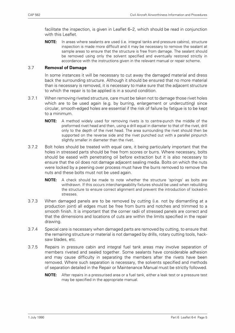
CAP 562 Civil Aircraft Airworthiness Information and Procedures
Part 6 Leaflet 6-4 Page 5
facilitate the inspection, is given in Leaflet 6–2, which should be read in conjunctionwith this Leaflet.
NOTE: In areas where sealants are used (i.e. integral tanks and pressure cabins), structureinspection is made more difficult and it may be necessary to remove the sealant atsample areas to ensure that the structure is free from damage. The sealant shouldbe removed using only the solvent specified and eventually restored strictly inaccordance with the instructions given in the relevant manual or repair scheme.
3.7 Removal of Damage
In some instances it will be necessary to cut away the damaged material and dressback the surrounding structure. Although it should be ensured that no more materialthan is necessary is removed, it is necessary to make sure that the adjacent structureto which the repair is to be applied is in a sound condition.
3.7.1 When removing riveted structure, care must be taken not to damage those rivet holeswhich are to be used again (e.g. by burring, enlargement or undercutting) sincecircular, smooth-edged holes are essential if the risk of failure by fatigue is to be keptto a minimum.
NOTE: A method widely used for removing rivets is to centre-punch the middle of thepreformed rivet head and then, using a drill equal in diameter to that of the rivet, drillonly to the depth of the rivet head. The area surrounding the rivet should then besupported on the reverse side and the rivet punched out with a parallel pinpunchslightly smaller in diameter than the rivet.
3.7.2 Bolt holes should be treated with equal care, it being particularly important that theholes in stressed parts should be free from scores or burrs. Where necessary, boltsshould be eased with penetrating oil before extraction but it is also necessary toensure that the oil does not damage adjacent sealing media. Bolts on which the nutswere locked by a peening over process must have the burrs removed to remove thenuts and these bolts must not be used again.
NOTE: A check should be made to note whether the structure 'springs' as bolts arewithdrawn. If this occurs interchangeability fixtures should be used when rebuildingthe structure to ensure correct alignment and prevent the introduction of locked-instresses.
3.7.3 When damaged panels are to be removed by cutting (i.e. not by dismantling at aproduction joint) all edges must be free from burrs and notches and trimmed to asmooth finish. It is important that the corner radii of stressed panels are correct andthat the dimensions and locations of cuts are within the limits specified in the repairdrawing.
3.7.4 Special care is necessary when damaged parts are removed by cutting, to ensure thatthe remaining structure or material is not damaged by drills, rotary cutting tools, hack-saw blades, etc.
3.7.5 Repairs in pressure cabin and integral fuel tank areas may involve separation ofmembers riveted and sealed together. Some sealants have considerable adhesionand may cause difficulty in separating the members after the rivets have beenremoved. Where such separation is necessary, the solvents specified and methodsof separation detailed in the Repair or Maintenance Manual must be strictly followed.
NOTE: After repairs in a pressurised area or a fuel tank, either a leak test or a pressure testmay be specified in the appropriate manual.
1 July 1990
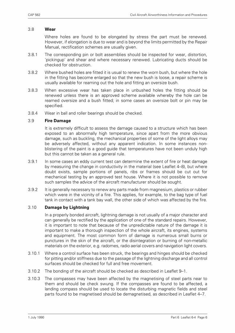
CAP 562 Civil Aircraft Airworthiness Information and Procedures
Part 6 Leaflet 6-4 Page 6
3.8 Wear
Where holes are found to be elongated by stress the part must be renewed.However, if elongation is due to wear and is beyond the limits permitted by the RepairManual, rectification schemes are usually given.
3.8.1 The corresponding pin or bolt assemblies should be inspected for wear, distortion,'pickingup' and shear and where necessary renewed. Lubricating ducts should bechecked for obstruction.
3.8.2 Where bushed holes are fitted it is usual to renew the worn bush, but where the holein the fitting has become enlarged so that the new bush is loose, a repair scheme isusually available for reaming out the hole and fitting an oversize bush.
3.8.3 When excessive wear has taken place in unbushed holes the fitting should berenewed unless there is an approved scheme available whereby the hole can bereamed oversize and a bush fitted; in some cases an oversize bolt or pin may bespecified.
3.8.4 Wear in ball and roller bearings should be checked.
3.9 Fire Damage
It is extremely difficult to assess the damage caused to a structure which has beenexposed to an abnormally high temperature, since apart from the more obviousdamage, such as buckling, the mechanical properties of some of the light alloys maybe adversely affected, without any apparent indication. In some instances non-blistering of the paint is a good guide that temperatures have not been unduly highbut this cannot be taken as a general rule.
3.9.1 In some cases an eddy current test can determine the extent of fire or heat damageby measuring the change in conductivity in the material (see Leaflet 4–8), but wheredoubt exists, sample portions of panels, ribs or frames should be cut out formechanical testing by an approved test house. Where it is not possible to removesuch samples the advice of the aircraft manufacturer should be sought.
3.9.2 It is generally necessary to renew any parts made from magnesium, plastics or rubberwhich were in the vicinity of a fire. This applies, for example, to the bag type of fueltank in contact with a tank bay wall, the other side of which was affected by the fire.
3.10 Damage by Lightning
In a properly bonded aircraft, lightning damage is not usually of a major character andcan generally be rectified by the application of one of the standard repairs. However,it is important to note that because of the unpredictable nature of the damage it isimportant to make a thorough inspection of the whole aircraft, its engines, systemsand equipment. The most common form of damage is numerous small burns orpunctures in the skin of the aircraft, or the disintegration or burning of non-metallicmaterials on the exterior, e.g. radomes, radio aerial covers and navigation light covers.
3.10.1 Where a control surface has been struck, the bearings and hinges should be checkedfor pitting and/or stiffness due to the passage of the lightning discharge and all controlsurfaces should be checked for full and free movement.
3.10.2 The bonding of the aircraft should be checked as described in Leaflet 9–1.
3.10.3 The compasses may have been affected by the magnetising of steel parts near tothem and should be check swung. If the compasses are found to be affected, alanding compass should be used to locate the disturbing magnetic fields and steelparts found to be magnetised should be demagnetised, as described in Leaflet 4–7.
1 July 1990
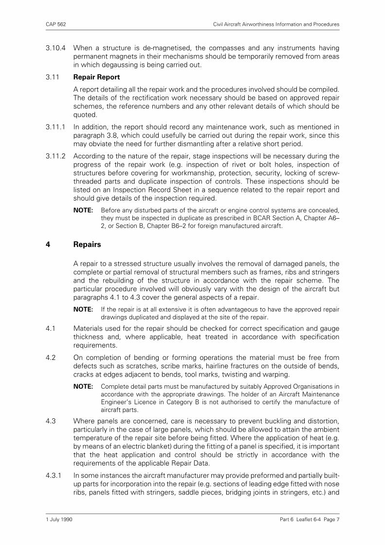
CAP 562 Civil Aircraft Airworthiness Information and Procedures
Part 6 Leaflet 6-4 Page 7
3.10.4 When a structure is de-magnetised, the compasses and any instruments havingpermanent magnets in their mechanisms should be temporarily removed from areasin which degaussing is being carried out.
3.11 Repair Report
A report detailing all the repair work and the procedures involved should be compiled.The details of the rectification work necessary should be based on approved repairschemes, the reference numbers and any other relevant details of which should bequoted.
3.11.1 In addition, the report should record any maintenance work, such as mentioned inparagraph 3.8, which could usefully be carried out during the repair work, since thismay obviate the need for further dismantling after a relative short period.
3.11.2 According to the nature of the repair, stage inspections will be necessary during theprogress of the repair work (e.g. inspection of rivet or bolt holes, inspection ofstructures before covering for workmanship, protection, security, locking of screw-threaded parts and duplicate inspection of controls. These inspections should belisted on an Inspection Record Sheet in a sequence related to the repair report andshould give details of the inspection required.
NOTE: Before any disturbed parts of the aircraft or engine control systems are concealed,they must be inspected in duplicate as prescribed in BCAR Section A, Chapter A6–2, or Section B, Chapter B6–2 for foreign manufactured aircraft.
4 Repairs
A repair to a stressed structure usually involves the removal of damaged panels, thecomplete or partial removal of structural members such as frames, ribs and stringersand the rebuilding of the structure in accordance with the repair scheme. Theparticular procedure involved will obviously vary with the design of the aircraft butparagraphs 4.1 to 4.3 cover the general aspects of a repair.
NOTE: If the repair is at all extensive it is often advantageous to have the approved repairdrawings duplicated and displayed at the site of the repair.
4.1 Materials used for the repair should be checked for correct specification and gaugethickness and, where applicable, heat treated in accordance with specificationrequirements.
4.2 On completion of bending or forming operations the material must be free fromdefects such as scratches, scribe marks, hairline fractures on the outside of bends,cracks at edges adjacent to bends, tool marks, twisting and warping.
NOTE: Complete detail parts must be manufactured by suitably Approved Organisations inaccordance with the appropriate drawings. The holder of an Aircraft MaintenanceEngineer’s Licence in Category B is not authorised to certify the manufacture ofaircraft parts.
4.3 Where panels are concerned, care is necessary to prevent buckling and distortion,particularly in the case of large panels, which should be allowed to attain the ambienttemperature of the repair site before being fitted. Where the application of heat (e.g.by means of an electric blanket) during the fitting of a panel is specified, it is importantthat the heat application and control should be strictly in accordance with therequirements of the applicable Repair Data.
4.3.1 In some instances the aircraft manufacturer may provide preformed and partially built-up parts for incorporation into the repair (e.g. sections of leading edge fitted with noseribs, panels fitted with stringers, saddle pieces, bridging joints in stringers, etc.) and
1 July 1990
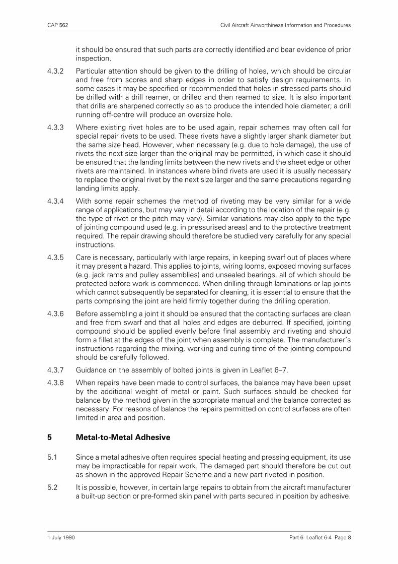
CAP 562 Civil Aircraft Airworthiness Information and Procedures
Part 6 Leaflet 6-4 Page 8
it should be ensured that such parts are correctly identified and bear evidence of priorinspection.
4.3.2 Particular attention should be given to the drilling of holes, which should be circularand free from scores and sharp edges in order to satisfy design requirements. Insome cases it may be specified or recommended that holes in stressed parts shouldbe drilled with a drill reamer, or drilled and then reamed to size. It is also importantthat drills are sharpened correctly so as to produce the intended hole diameter; a drillrunning off-centre will produce an oversize hole.
4.3.3 Where existing rivet holes are to be used again, repair schemes may often call forspecial repair rivets to be used. These rivets have a slightly larger shank diameter butthe same size head. However, when necessary (e.g. due to hole damage), the use ofrivets the next size larger than the original may be permitted, in which case it shouldbe ensured that the landing limits between the new rivets and the sheet edge or otherrivets are maintained. In instances where blind rivets are used it is usually necessaryto replace the original rivet by the next size larger and the same precautions regardinglanding limits apply.
4.3.4 With some repair schemes the method of riveting may be very similar for a widerange of applications, but may vary in detail according to the location of the repair (e.g.the type of rivet or the pitch may vary). Similar variations may also apply to the typeof jointing compound used (e.g. in pressurised areas) and to the protective treatmentrequired. The repair drawing should therefore be studied very carefully for any specialinstructions.
4.3.5 Care is necessary, particularly with large repairs, in keeping swarf out of places whereit may present a hazard. This applies to joints, wiring looms, exposed moving surfaces(e.g. jack rams and pulley assemblies) and unsealed bearings, all of which should beprotected before work is commenced. When drilling through laminations or lap jointswhich cannot subsequently be separated for cleaning, it is essential to ensure that theparts comprising the joint are held firmly together during the drilling operation.
4.3.6 Before assembling a joint it should be ensured that the contacting surfaces are cleanand free from swarf and that all holes and edges are deburred. If specified, jointingcompound should be applied evenly before final assembly and riveting and shouldform a fillet at the edges of the joint when assembly is complete. The manufacturer’sinstructions regarding the mixing, working and curing time of the jointing compoundshould be carefully followed.
4.3.7 Guidance on the assembly of bolted joints is given in Leaflet 6–7.
4.3.8 When repairs have been made to control surfaces, the balance may have been upsetby the additional weight of metal or paint. Such surfaces should be checked forbalance by the method given in the appropriate manual and the balance corrected asnecessary. For reasons of balance the repairs permitted on control surfaces are oftenlimited in area and position.
5 Metal-to-Metal Adhesive
5.1 Since a metal adhesive often requires special heating and pressing equipment, its usemay be impracticable for repair work. The damaged part should therefore be cut outas shown in the approved Repair Scheme and a new part riveted in position.
5.2 It is possible, however, in certain large repairs to obtain from the aircraft manufacturera built-up section or pre-formed skin panel with parts secured in position by adhesive.
1 July 1990

CAP 562 Civil Aircraft Airworthiness Information and Procedures
Part 6 Leaflet 6-4 Page 9
The repair then consists of removing the damaged section complete and riveting thereplacement section into position.
5.3 When it is necessary to remove parts which are secured with adhesive, e.g. astringer, this can be done as shown in Figure 1. Care should be taken to avoiddamaging any parts or material other than those to be removed.
NOTE: When paint is removed in the area of a metal-to-metal adhesive joint, only the paintstripper stipulated should be used. Some strippers may have a deleterious effect onmetal-to-metal adhesives.
6 Repairs by Welding
Repairs by means of welding are often specified for welded structures such aslanding gear structures, engine mountings, etc. The welding procedure to be used willdepend on the design and manufacture of the structure and will be fully detailed inthe Repair Data. It will often be necessary to use jigs or jury structures to ensure thatthe main structure is held in the correct position during welding.
6.1 Welding Procedures
Some of the welding procedures most commonly used for aircraft repairs are thefollowing: Oxy-Acetylene Welding, Arc Welding and Spot Welding.
6.1.1 As prescribed in Chapter A8–10 of BCAR, welders must be approved by the CAA.
6.1.2 Where highly stressed components have been repaired by welding they should besubmitted to one of the non-destructive examination tests outlined in the Part 4 seriesof Leaflets.
6.1.3 Before welding is commenced any protective treatment in the area of the repair mustbe completely removed and the parts prepared in accordance with the repair schemeapplicable.
Figure 1 Removal of Bonded Component
LENGTH OF DAMAGED STRINGER TO BE REMOVED
OLD MACHINE HACK-SAW BLADE GROUND TO A KNIFE-EDGE
V-SHAPED CUT-OUT DOWN TO SKIN
BONDED JOINT
1 July 1990
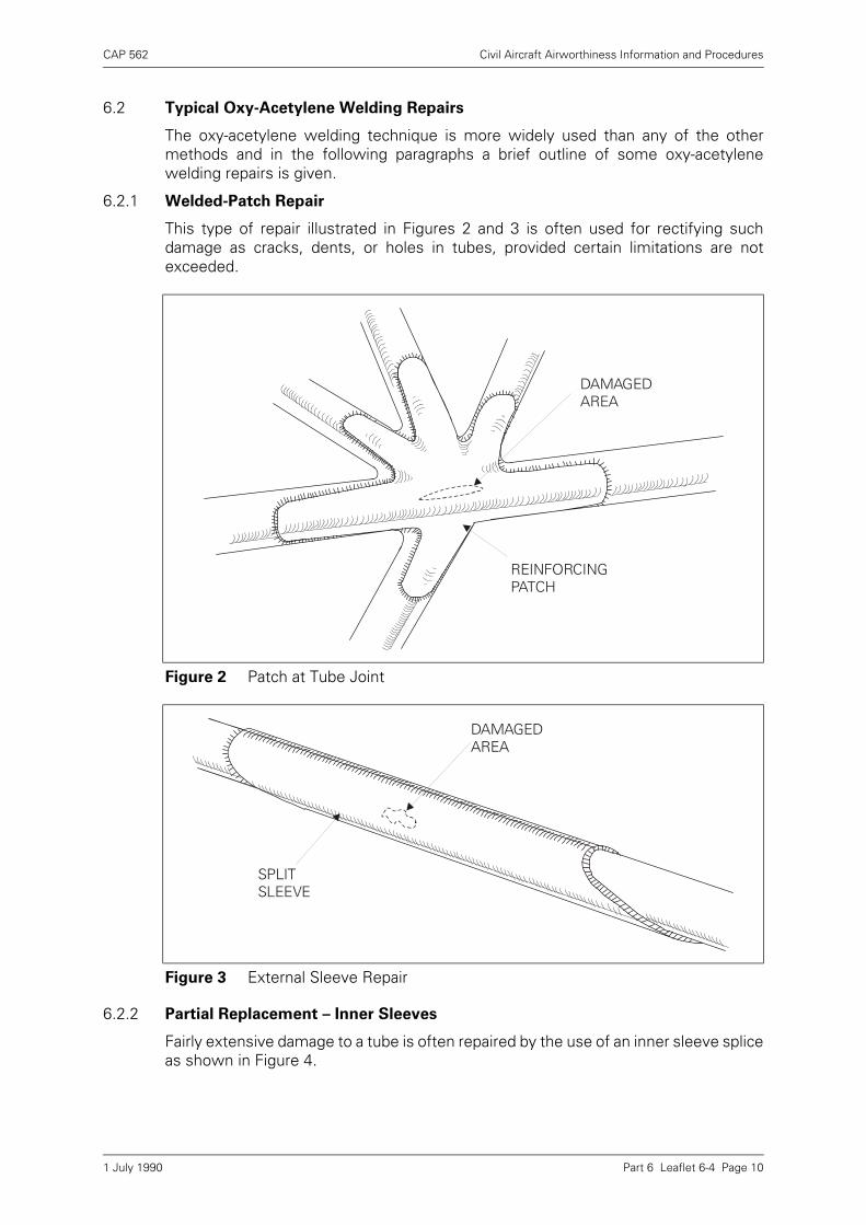
CAP 562 Civil Aircraft Airworthiness Information and Procedures
Part 6 Leaflet 6-4 Page 10
6.2 Typical Oxy-Acetylene Welding Repairs
The oxy-acetylene welding technique is more widely used than any of the othermethods and in the following paragraphs a brief outline of some oxy-acetylenewelding repairs is given.
6.2.1 Welded-Patch Repair
This type of repair illustrated in Figures 2 and 3 is often used for rectifying suchdamage as cracks, dents, or holes in tubes, provided certain limitations are notexceeded.
6.2.2 Partial Replacement – Inner Sleeves
Fairly extensive damage to a tube is often repaired by the use of an inner sleeve spliceas shown in Figure 4.
Figure 2 Patch at Tube Joint
Figure 3 External Sleeve Repair
REINFORCING PATCH
DAMAGED AREA
DAMAGED AREA
SPLIT SLEEVE
1 July 1990

CAP 562 Civil Aircraft Airworthiness Information and Procedures
Part 6 Leaflet 6-4 Page 11
a) The condition and location of the associated structure should be checked andsecured to prevent movement when the damaged portion is removed.
b) The damaged portion of the tube should be cut out using 30° or 45° diagonal cutsand the burrs inside the tube should be removed.
c) A replacement piece of tube should be cut to fit where the damaged portion wasremoved and a gap of approximately 2·4 mm (3/32in) should be left for welding.
d) The inner sleeves should be cut to length and a check made to ensure that theyslide smoothly in both tubes. If rosette holes are required they should next be cutand the burrs removed; when a draw wire is required it should be welded intoposition.
e) The inner sleeves should be marked at the half-way position, fitted into thereplacement tube and positioned with the midpoint at the diagonal cut.
f) The repair should be completed by welding at the diagonal cuts and at the rosetteholes or the draw wire hole as applicable.
6.3 Partial Replacement – Outer Sleeves
This method should only be used where it is impracticable to use inner sleeves. Theprocedure is basically the same as for inner sleeves except that the replacement tubeshould be cut square at both ends and the outer sleeves scarfed at 30° or 45°.
6.4 Protective Treatment
After welding, the parts concerned should be thoroughly descaled, cleaned and theprotective treatment restored.
7 Gauging Damage
7.1 Where a score, dent, or corrosion damage in a stressed part has been removed byblending out into a smooth surfaced hollow depression, the maximum depth of the
Figure 4 Internal Sleeve Repair
WELDING GAP
REPLACEMENT TUBE
INNER SLEEVE
ROSETTE HOLE
SLEEVE DRAW WIRE
DRAW WIRE HOLE
1 July 1990
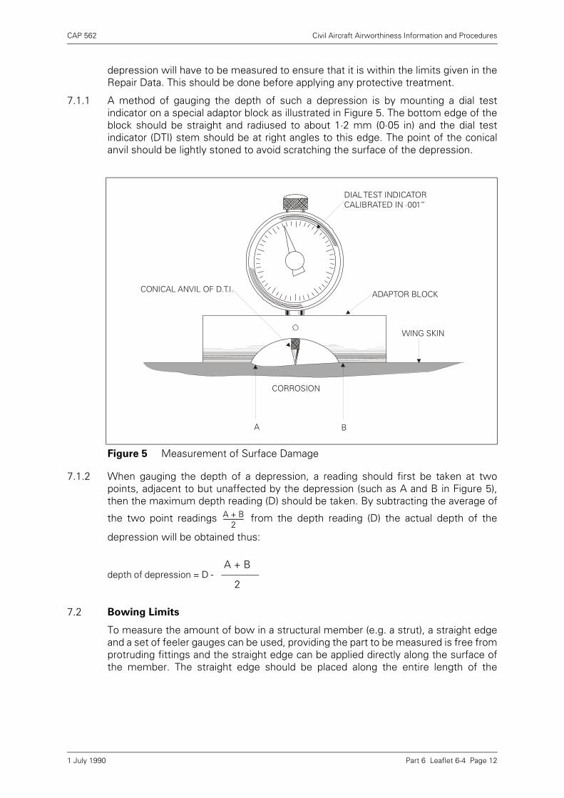
CAP 562 Civil Aircraft Airworthiness Information and Procedures
Part 6 Leaflet 6-4 Page 12
depression will have to be measured to ensure that it is within the limits given in theRepair Data. This should be done before applying any protective treatment.
7.1.1 A method of gauging the depth of such a depression is by mounting a dial testindicator on a special adaptor block as illustrated in Figure 5. The bottom edge of theblock should be straight and radiused to about 1·2 mm (0·05 in) and the dial testindicator (DTI) stem should be at right angles to this edge. The point of the conicalanvil should be lightly stoned to avoid scratching the surface of the depression..
7.1.2 When gauging the depth of a depression, a reading should first be taken at twopoints, adjacent to but unaffected by the depression (such as A and B in Figure 5),then the maximum depth reading (D) should be taken. By subtracting the average of
the two point readings from the depth reading (D) the actual depth of the
depression will be obtained thus:
7.2 Bowing Limits
To measure the amount of bow in a structural member (e.g. a strut), a straight edgeand a set of feeler gauges can be used, providing the part to be measured is free fromprotruding fittings and the straight edge can be applied directly along the surface ofthe member. The straight edge should be placed along the entire length of the
Figure 5 Measurement of Surface Damage
depth of depression = D - A + B
2
DIAL TEST INDICATOR CALIBRATED IN ·001”
ADAPTOR BLOCK
WING SKIN
CONICAL ANVIL OF D.T.I.
CORROSION
A B
A B+2
-----------------
1 July 1990
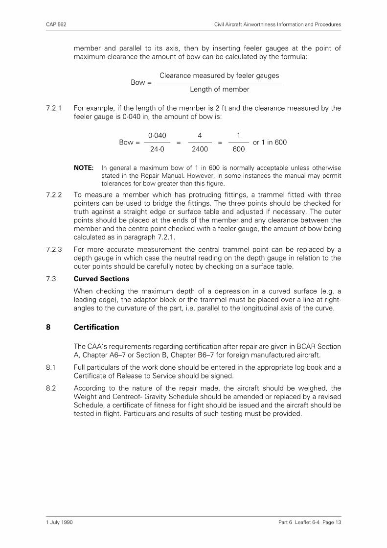
CAP 562 Civil Aircraft Airworthiness Information and Procedures
Part 6 Leaflet 6-4 Page 13
member and parallel to its axis, then by inserting feeler gauges at the point ofmaximum clearance the amount of bow can be calculated by the formula:
7.2.1 For example, if the length of the member is 2 ft and the clearance measured by thefeeler gauge is 0·040 in, the amount of bow is:
NOTE: In general a maximum bow of 1 in 600 is normally acceptable unless otherwisestated in the Repair Manual. However, in some instances the manual may permittolerances for bow greater than this figure.
7.2.2 To measure a member which has protruding fittings, a trammel fitted with threepointers can be used to bridge the fittings. The three points should be checked fortruth against a straight edge or surface table and adjusted if necessary. The outerpoints should be placed at the ends of the member and any clearance between themember and the centre point checked with a feeler gauge, the amount of bow beingcalculated as in paragraph 7.2.1.
7.2.3 For more accurate measurement the central trammel point can be replaced by adepth gauge in which case the neutral reading on the depth gauge in relation to theouter points should be carefully noted by checking on a surface table.
7.3 Curved Sections
When checking the maximum depth of a depression in a curved surface (e.g. aleading edge), the adaptor block or the trammel must be placed over a line at right-angles to the curvature of the part, i.e. parallel to the longitudinal axis of the curve.
8 Certification
The CAA’s requirements regarding certification after repair are given in BCAR SectionA, Chapter A6–7 or Section B, Chapter B6–7 for foreign manufactured aircraft.
8.1 Full particulars of the work done should be entered in the appropriate log book and aCertificate of Release to Service should be signed.
8.2 According to the nature of the repair made, the aircraft should be weighed, theWeight and Centreof- Gravity Schedule should be amended or replaced by a revisedSchedule, a certificate of fitness for flight should be issued and the aircraft should betested in flight. Particulars and results of such testing must be provided.
Bow =Clearance measured by feeler gauges
Length of member
Bow =0·040
= 4
= 1
or 1 in 60024·0 2400 600
1 July 1990

INTENTIONALLY LEFT BLANK

CAP 562 Civil Aircraft Airworthiness Information and Procedures
Part 6 Leaflet 6-5 Page 1
Leaflet 6-5 Rigging Checks on Aircraft
1 Introduction
This Leaflet gives guidance on methods of checking the relative alignment andadjustment of aircraft main components and should be read in conjunction with theappropriate manual for the aircraft concerned. Guidance on checking the rigging ofaircraft after abnormal flight loads or heavy landings is given in Leaflet 6-3.
2 Levelling the Aircraft
The position or angle of main components is related to a longitudinal datum lineparallel to the aircraft centre line and a lateral datum line parallel to a line joining thewing tips. Before these positions or angles are checked, the aircraft should (generally)be brought to the rigging position (i.e. with the lateral and longitudinal datum lineshorizontal) by means of jacks or trestles, depending on the particular aircraft type,with the wheels just clear of the ground.
2.1 For the purpose of checking the level of smaller types of aircraft, fixed or portabledatum pegs or blocks, on which can be rested a straight-edge and spirit level andwhich are generally attached to the fuselage parallel to or co-incident with the datumlines, are used, although in some instances parts of the structure which run parallelwith the datum lines (e.g. top longerons or canopy rails of some aircraft) may beutilised. A typical levelling arrangement is shown in Figure 1.
2.2 The methods of checking the levelling given in paragraph 2.1 are also applicable tomany of the larger types of aircraft, but other methods are sometimes used, e.g. the'grid' method illustrated in Figure 2. The grid plate is a permanent fixture on the floor
Figure 1 Datum Lines and Levelling Points
LONGITUDINAL DATUM
LONGITUDINAL DATUM PEGS
LATERAL DATUM BRACKETS
LATERAL DATUM
=
=
= =
1 July 1990
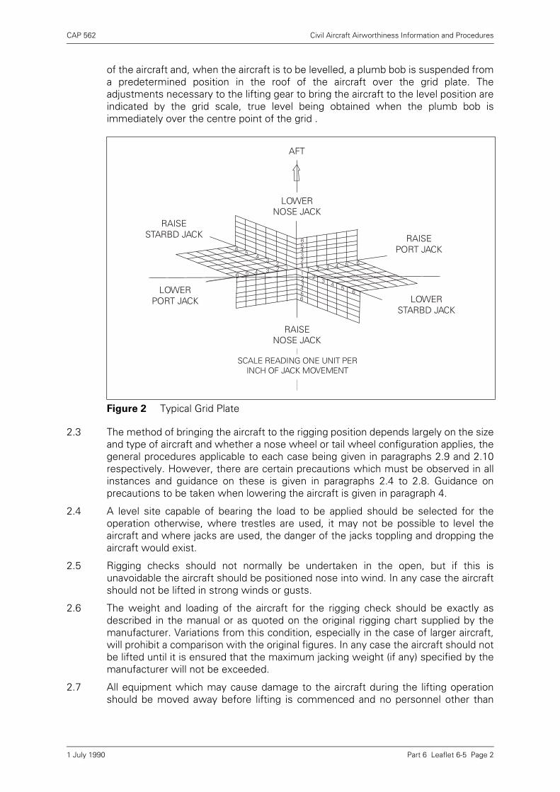
CAP 562 Civil Aircraft Airworthiness Information and Procedures
Part 6 Leaflet 6-5 Page 2
of the aircraft and, when the aircraft is to be levelled, a plumb bob is suspended froma predetermined position in the roof of the aircraft over the grid plate. Theadjustments necessary to the lifting gear to bring the aircraft to the level position areindicated by the grid scale, true level being obtained when the plumb bob isimmediately over the centre point of the grid .
2.3 The method of bringing the aircraft to the rigging position depends largely on the sizeand type of aircraft and whether a nose wheel or tail wheel configuration applies, thegeneral procedures applicable to each case being given in paragraphs 2.9 and 2.10respectively. However, there are certain precautions which must be observed in allinstances and guidance on these is given in paragraphs 2.4 to 2.8. Guidance onprecautions to be taken when lowering the aircraft is given in paragraph 4.
2.4 A level site capable of bearing the load to be applied should be selected for theoperation otherwise, where trestles are used, it may not be possible to level theaircraft and where jacks are used, the danger of the jacks toppling and dropping theaircraft would exist.
2.5 Rigging checks should not normally be undertaken in the open, but if this isunavoidable the aircraft should be positioned nose into wind. In any case the aircraftshould not be lifted in strong winds or gusts.
2.6 The weight and loading of the aircraft for the rigging check should be exactly asdescribed in the manual or as quoted on the original rigging chart supplied by themanufacturer. Variations from this condition, especially in the case of larger aircraft,will prohibit a comparison with the original figures. In any case the aircraft should notbe lifted until it is ensured that the maximum jacking weight (if any) specified by themanufacturer will not be exceeded.
2.7 All equipment which may cause damage to the aircraft during the lifting operationshould be moved away before lifting is commenced and no personnel other than
Figure 2 Typical Grid Plate
111 11
2
2
2
2
22
3 3
3
3
3
3
4
4
44
4
4
6 5
55
5
5
5
6
6
6
6
6
LOWER NOSE JACK
RAISE NOSE JACK
RAISE PORT JACK
LOWER STARBD JACK
RAISE STARBD JACK
LOWER PORT JACK
SCALE READING ONE UNIT PER INCH OF JACK MOVEMENT
AFT
1 July 1990
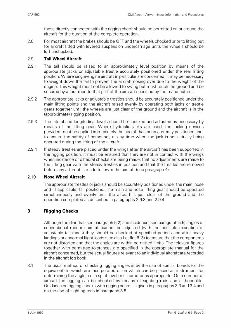
CAP 562 Civil Aircraft Airworthiness Information and Procedures
Part 6 Leaflet 6-5 Page 3
those directly connected with the rigging check should be permitted on or around theaircraft for the duration of the complete operation.
2.8 For most aircraft the brakes should be OFF and the wheels chocked prior to lifting butfor aircraft fitted with levered suspension undercarriage units the wheels should beleft unchocked.
2.9 Tail Wheel Aircraft
2.9.1 The tail should be raised to an approximately level position by means of theappropriate jacks or adjustable trestle accurately positioned under the rear liftingposition. Where single-engine aircraft in particular are concerned, it may be necessaryto weight down the tail to prevent the aircraft nosing over due to the weight of theengine. This weight must not be allowed to swing but must touch the ground and besecured by a taut rope to that part of the aircraft specified by the manufacturer.
2.9.2 The appropriate jacks or adjustable trestles should be accurately positioned under themain lifting points and the aircraft raised evenly by operating both jacks or trestlegears together until the wheels are just clear of the ground and the aircraft is in the(approximate) rigging position.
2.9.3 The lateral and longitudinal levels should be checked and adjusted as necessary bymeans of the lifting gear. Where hydraulic jacks are used, the locking devicesprovided must be applied immediately the aircraft has been correctly positioned and,to ensure the safety of personnel, at any time when the jack is not actually beingoperated during the lifting of the aircraft.
2.9.4 If steady trestles are placed under the wings after the aircraft has been supported inthe rigging position, it must be ensured that they are not in contact with the wingswhen incidence or dihedral checks are being made, that no adjustments are made tothe lifting gear with the steady trestles in position and that the trestles are removedbefore any attempt is made to lower the aircraft (see paragraph 4).
2.10 Nose Wheel Aircraft
The appropriate trestles or jacks should be accurately positioned under the main, noseand (if applicable) tail positions. The main and nose lifting gear should be operatedsimultaneously and evenly until the aircraft is just clear of the ground and theoperation completed as described in paragraphs 2.9.3 and 2.9.4.
3 Rigging Checks
Although the dihedral (see paragraph 5.2) and incidence (see paragraph 5.5) angles ofconventional modern aircraft cannot be adjusted (with the possible exception ofadjustable tailplanes) they should be checked at specified periods and after heavylandings or abnormal flight loads (see also Leaflet 6–3) to ensure that the componentsare not distorted and that the angles are within permitted limits. The relevant figurestogether with permitted tolerances are specified in the appropriate manual for theaircraft concerned, but the actual figures relevant to an individual aircraft are recordedin the aircraft log book.
3.1 The usual method of checking rigging angles is by the use of special boards (or theequivalent) in which are incorporated or on which can be placed an instrument fordetermining the angle, i.e. a spirit level or clinometer as appropriate. On a number ofaircraft the rigging can be checked by means of sighting rods and a theodolite.Guidance on rigging checks with rigging boards is given in paragraphs 3.3 and 3.4 andon the use of sighting rods in paragraph 3.5.
1 July 1990
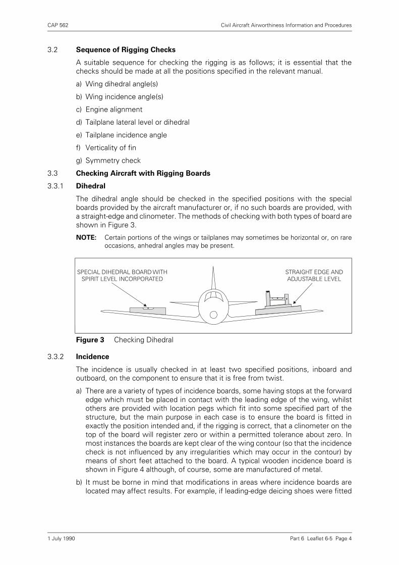
CAP 562 Civil Aircraft Airworthiness Information and Procedures
Part 6 Leaflet 6-5 Page 4
3.2 Sequence of Rigging Checks
A suitable sequence for checking the rigging is as follows; it is essential that thechecks should be made at all the positions specified in the relevant manual.
a) Wing dihedral angle(s)
b) Wing incidence angle(s)
c) Engine alignment
d) Tailplane lateral level or dihedral
e) Tailplane incidence angle
f) Verticality of fin
g) Symmetry check
3.3 Checking Aircraft with Rigging Boards
3.3.1 Dihedral
The dihedral angle should be checked in the specified positions with the specialboards provided by the aircraft manufacturer or, if no such boards are provided, witha straight-edge and clinometer. The methods of checking with both types of board areshown in Figure 3.
NOTE: Certain portions of the wings or tailplanes may sometimes be horizontal or, on rareoccasions, anhedral angles may be present.
3.3.2 Incidence
The incidence is usually checked in at least two specified positions, inboard andoutboard, on the component to ensure that it is free from twist.
a) There are a variety of types of incidence boards, some having stops at the forwardedge which must be placed in contact with the leading edge of the wing, whilstothers are provided with location pegs which fit into some specified part of thestructure, but the main purpose in each case is to ensure the board is fitted inexactly the position intended and, if the rigging is correct, that a clinometer on thetop of the board will register zero or within a permitted tolerance about zero. Inmost instances the boards are kept clear of the wing contour (so that the incidencecheck is not influenced by any irregularities which may occur in the contour) bymeans of short feet attached to the board. A typical wooden incidence board isshown in Figure 4 although, of course, some are manufactured of metal.
b) It must be borne in mind that modifications in areas where incidence boards arelocated may affect results. For example, if leading-edge deicing shoes were fitted
Figure 3 Checking Dihedral
STRAIGHT EDGE AND ADJUSTABLE LEVEL
SPECIAL DIHEDRAL BOARD WITH SPIRIT LEVEL INCORPORATED
1 July 1990
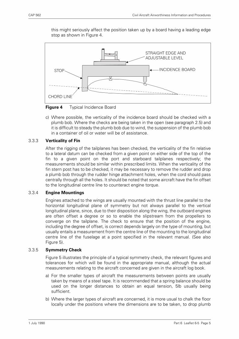
CAP 562 Civil Aircraft Airworthiness Information and Procedures
Part 6 Leaflet 6-5 Page 5
this might seriously affect the position taken up by a board having a leading edgestop as shown in Figure 4.
c) Where possible, the verticality of the incidence board should be checked with aplumb bob. Where the checks are being taken in the open (see paragraph 2.5) andit is difficult to steady the plumb bob due to wind, the suspension of the plumb bobin a container of oil or water will be of assistance.
3.3.3 Verticality of Fin
After the rigging of the tailplanes has been checked, the verticality of the fin relativeto a lateral datum can be checked from a given point on either side of the top of thefin to a given point on the port and starboard tailplanes respectively; themeasurements should be similar within prescribed limits. When the verticality of thefin stern post has to be checked, it may be necessary to remove the rudder and dropa plumb bob through the rudder hinge attachment holes, when the cord should passcentrally through all the holes. It should be noted that some aircraft have the fin offsetto the longitudinal centre line to counteract engine torque.
3.3.4 Engine Mountings
Engines attached to the wings are usually mounted with the thrust line parallel to thehorizontal longitudinal plane of symmetry but not always parallel to the verticallongitudinal plane, since, due to their disposition along the wing, the outboard enginesare often offset a degree or so to enable the slipstream from the propellers toconverge on the tailplane. The check to ensure that the position of the engine,including the degree of offset, is correct depends largely on the type of mounting, butusually entails a measurement from the centre line of the mounting to the longitudinalcentre line of the fuselage at a point specified in the relevant manual. (See alsoFigure 5).
3.3.5 Symmetry Check
Figure 5 illustrates the principle of a typical symmetry check, the relevant figures andtolerances for which will be found in the appropriate manual, although the actualmeasurements relating to the aircraft concerned are given in the aircraft log book.
a) For the smaller types of aircraft the measurements between points are usuallytaken by means of a steel tape. It is recommended that a spring balance should beused on the longer distances to obtain an equal tension, 5lb usually beingsufficient.
b) Where the larger types of aircraft are concerned, it is more usual to chalk the floorlocally under the positions where the dimensions are to be taken, to drop plumb
Figure 4 Typical Incidence Board
INCIDENCE BOARD
CHORD LINE
STOP
STRAIGHT EDGE AND ADJUSTABLE LEVEL
1 July 1990

CAP 562 Civil Aircraft Airworthiness Information and Procedures
Part 6 Leaflet 6-5 Page 6
bobs from the checking points, marking the floor with an 'X' immediately under thepoint of each plumb bob and then to measure the distance between the centre ofthe markings. This method has the advantages of ensuring more accuratemeasurement and reducing the amount of walking necessary on main planes andtailplanes.
3.4 Rigging Checks on Biplanes
In general the rigging checks applicable to single-engined biplanes during reassemblyafter overhaul are as follows, but specific requirements relating to a particular type ofaircraft should be ascertained from the relevant approved manual. The use of riggingboards, etc., is described in paragraph 3.3, as are other checks (such as the symmetrycheck) which are not peculiar to biplanes.
3.4.1 The fuselage should be levelled laterally and longitudinally as described in paragraph2. The centre-section should be placed on suitable trestles and the centre-sectionstruts and wires (complete with fork-ends) attached.
NOTE: It is important that the fork-ends should be screwed the same number of turns oneach end of the wire to provide for subsequent adjustment.
3.4.2 The centre-section should be erected onto the fuselage and the stagger (paragraph5.7) and lateral symmetry checked. The stagger should be checked by droppingplumb bobs from the leading edge of the upper portion of the centre-section (or otherdefined position) and measuring the distance from the plumb bobs to the leading
Figure 5 Symmetry Check
1 July 1990

CAP 562 Civil Aircraft Airworthiness Information and Procedures
Part 6 Leaflet 6-5 Page 7
edge of the lower portion of the centre-section (or other defined position). Ifnecessary, the stagger can be adjusted by means of the front centre-section strutson most aircraft of this type. The symmetry about the centre line should be checkedby measuring from plumb bobs to the sides of the fuselage and can be adjusted, ifnecessary, by means of the bracing wires.
NOTE: It is essential that the centre-section rigging checks should be accurately carried out,since small errors in the centre-section bracing can result in large errors in thegeneral rigging.
3.4.3 The port (or starboard) top main plane should be attached to the centre-section, carebeing taken to ensure that the main plane is adequately supported during theassembly. The landing wires (see paragraph 5.4) should then be attached to thecentre-section, the port (or starboard) lower main plane attached to the centre-section, the interplane struts, flying wires (paragraph 5.3) and incidence wires (seeparagraph 5.6) fitted and the whole assembly lightly tensioned up. The completedside of the aircraft should be steadied with a trestle whilst the opposite side isassembled in the same order.
NOTE: Although usually of similar appearance, front and rear interplane struts are usually ofslightly different lengths to compensate for wing contour, thus it is important toensure that the correct strut has been fitted in the correct position.
3.4.4 After assembly the fuselage level should be re-checked and adjusted as necessary,after which the main planes should be trued-up by adjustments to the appropriatewires, the aim being to achieve the correct dihedral first and then to work theincidence and stagger together. Care must be taken during rigging to ensure that themain flying and landing wires are not over-tensioned to the extent of bowing the mainplane spars or interplane struts.
NOTE: The specified lengths and permitted tolerances applicable to all wires are given inthe rigging diagrams appropriate to the aircraft type, but the actual figures to whichthe aircraft had previously been rigged is recorded in the aircraft log book. If usingthe same components it is advisable to re-rig to the log book figures, since thesemay have been determined specifically to counteract a flying fault.
3.4.5 After the rigging of the main planes has been completed, it should be ensured that allfork- ends, etc., are in safety, are not 'butting' against the ends of the fitting and havebeen correctly locked, that the wires are in streamline and that anti-chafing discs andspreader bars are correctly fitted to prevent vibration of the wires.
3.4.6 Empennage
The empennage should be attached in accordance with the instructions contained inthe relevant manual and adjusted (where this is possible) to within the limits specifiedin the relevant rigging diagram. It should be noted that the tailplane struts are usuallyhanded and, unless these are correctly positioned, the fairings will not be in line offlight.
NOTE: Tailplanes provided with an adjustment mechanism must be set to the neutralposition before checking is commenced.
3.4.7 Twin-Engine Biplanes
The general procedure for rigging twin-engined biplanes is basically similar to thatdescribed above for single-engined biplanes but it must be ensured that the weightof the engines is taken up on the appropriate struts before completing the generalrigging.
1 July 1990
CAP 562 Civil Aircraft Airworthiness Information and Procedures
Part 6 Leaflet 6-5 Page 8
3.5 Checking Rigging with Sighting Rods
This method of checking rigging is used mainly on the larger types of aircraft andconsists basically of sighting with a theodolite the positions of datum marks on aseries of rods of graduated lengths, each of which is inserted into a specified jiggedposition on the underside of the aircraft.
3.5.1 For the initial check, the aircraft should be brought to the rigging position (seeparagraph 2) and the sighting rods inserted at the appropriate stations.
NOTE: Since any rod can be fitted into any socket, it is important to ensure that the rods areinserted in their correct positions.
3.5.2 A theodolite, erected at an appropriate distance and position from the aircraft shouldbe levelled up with the datum mark on the master sighting rod (usually the shortestrod fitted under the fuselage) and then readings should be taken from this sightingline at each rod station and recorded. A typical method of taking the readings isillustrated in Figure 6.
3.5.3 The readings thus obtained must be within the tolerances permitted by themanufacturer (details of which are usually included in the rigging drawing) andentered in the aircraft log book for permanent record.
3.5.4 There are two basic methods applicable to the use of sighting rods and these aredescribed below.
a) On some types of aircraft the sockets into which the sighting rods are inserted areadjustable in the vertical direction so that once variations from nominal figureshave been recorded, the rods can be 'zeroed' and permanently locked. Thus thesighting line on all subsequent checks should in fact coincide with the datummarks on all the rods if the rigging is correct. Rods used for this method have thesingle datum as illustrated in Figure 6.
NOTES: 1) A method which provides accurate vertical adjustment and rigidity for atheodolite is to mount it on a hydraulic jack.
2) It may not be possible in every instance to obtain a reading on everysighting rod from one theodolite position, in which case the theodoliteshould be appropriately repositioned, realigned on the master rod andthe check continued in the same manner as before.
Figure 6 Typical Method of Taking Readings
12
34
5
THEORETICAL SIGHTING LINE
ACTUAL SIGHTING LINE
RULER
THEODOLITE
X
1 July 1990
CAP 562 Civil Aircraft Airworthiness Information and Procedures
Part 6 Leaflet 6-5 Page 9
b) The second method is to use sighting rods on which are marked the datum line,on either side of which is also marked graduations indicating the permissibletolerance on the nominal figure in increments of 1/4 degrees. With this method thesockets into which the rods are inserted are not adjustable and subsequentreadings should give the actual figures recorded on the initial check.
NOTE: When rods of the 'screw-in' type are used it should be ensured that they are fullyscrewed home before the check is commenced.
3.5.5 When a component (e.g. wing or tailplane) is changed, it will be necessary to againcarry out the initial check to ascertain actual figures.
4 Lowering the Aircraft
Before any attempt is made to lower the aircraft to the ground it must be ensured thatwing supports and any other equipment which might foul and damage the aircraft aremoved clear. The aircraft should be lowered evenly and, when the aircraft weight isaccepted on the undercarriage, the jacks should be further lowered to ensure thatthey can be removed without fouling the aircraft structure.
5 Definitions
5.1 Anhedral. An inclination outwards and downwards relative to the lateral datum.
5.2 Dihedral. The angle (or angles) at which the wings and tailplanes are inclinedoutward and upward relative to the lateral datum.
5.3 Flying Wires. Wires the principal function of which is to transfer the lift of the mainplanes to the main structure. These wires are sometimes termed 'lift wires'.
5.4 Landing Wires. Wires which brace the main plane against forces opposite indirection to the direction of lift, as occur, for example, in landing. These wires aresometimes termed 'anti-lift wires'.
5.5 Incidence. The angle between the chord line of the wing or tailplane and thelongitudinal datum.
5.6 Incidence Wires. Wires bracing the main plane structure in the plane of a pair offront and rear struts.
5.7 Stagger. The distance between the leading edge of the lower plane and theprojection of the leading edge of the upper plane on the chord of the lower plane.
1 July 1990

INTENTIONALLY LEFT BLANK
CAP 562 Civil Aircraft Airworthiness Information and Procedures
Part 6 Leaflet 6-6 Page 1
Leaflet 6-6 The Effect of Disturbed Airflow on Aeroplane
Behaviour
1 Introduction
1.1 This Leaflet gives general guidance on the cause and effect of disturbed airflow onaeroplane behaviour, with particular reference to high-performance aeroplanes. Itemphasises the need for special care in the preservation of correct airframe contoursbecause of the serious effect on aeroplane behaviour, particularly at high speeds, ofseemingly trivial discontinuities in contour, profile, etc.
1.2 It is important that the point of transition from laminar to turbulent airflow on aerofoilsurfaces occurs at the position intended in the design. At high subsonic speeds thetransition point may be designed to be effective at a position some 30 to 50% alongthe wing chord from the leading edge and can be very sensitive to even smallprotuberances or discontinuities on the wing surface.
1.3 Faulty contours can have dangerous effects on an aeroplane flying at or near thestalling speed, whilst rough surfaces, badly fitting joints, gaps, etc., will adverselyaffect, to some extent, performance in all regimes of flight. However, defects whichmay be considered of minor importance to low-speed aeroplanes may have aconsiderable influence on aeroplanes flying at higher speeds. For example, thebehaviour of the airflow over an aileron can be seriously affected by those departuresfrom design which influence the position of the transition point, thus affecting theresponse, or the rate of response, of the aeroplane, the trim and the drag.
1.4 No attempt is made in this Leaflet to describe any aerodynamic principle or theory;any description or illustration given is solely to help clarify the 'cause and effect' ofthe defect and is not considered to be a formal aerodynamic representation.
1.5 Since the methods used to determine the causes of flying faults (and the methods ofrectification) vary considerably with different types of aeroplanes, it is essential thatthe manufacturer’s instructions, as specified in the relevant manuals, should becarefully followed.
1.6 Guidance on the general rigging of aeroplanes is given in Leaflet 6–5 and on theinspection of aeroplanes after heavy landings or abnormal flight loads in Leaflet 6–3.
2 General
In high performance aeroplanes the surfaces subjected to airflow are manufacturedto within relatively close contour and gap limits and these limits have to be maintainedif increased drag and other penalties are to be avoided. In this connection, the mostcritical areas of the aeroplane, where high accuracy in manufacture and the greatestcare in maintenance are involved, include the leading edges of wings, tailplane andflying control surfaces, shrouds and trailing edges, engine intakes and static-ventareas. However, it should be noted that production tolerances are normally permittedand thus it should never be necessary to adjust any dimension to give an accuracygreater than that required by design solely for the purpose of maintainingperformance standards.
2.1 Modern high performance aeroplanes are so manufactured that the originalsmoothness of contour is maintained more effectively than in previous generationsof aeroplanes (e.g. by the use of machined skin panels). Nevertheless, small
1 July 1990

CAP 562 Civil Aircraft Airworthiness Information and Procedures
Part 6 Leaflet 6-6 Page 2
departures from the prescribed alignment and contours can occur during service andmay be very difficult to recognise. Although such irregularities may have a negligibleeffect at lower speeds, changes of trim may occur as the aeroplane reaches itslimiting Mach number.
NOTE: Although an aeroplane may be flying at subsonic speed, it is not unusual for theairflow over certain sections to be at transonic or supersonic speed.
2.2 Apart from changes of attitude and trim which may or may not occur due todepartures from the original aerodynamic contours (e.g. malalignment of controlsurfaces, incorrect fitting of inspection panels, fairings and cowlings, dents orwrinkles in wing skins, protruding bolt heads, etc.), such defects will also cause anincrease in drag, resulting in a deterioration in aeroplane performance and range. Forlong-distance flights the results could be a marked increase in fuel consumption andseriously reduced fuel reserves.
2.3 In addition to defects which may be 'built in' as described in paragraph 2.2, it shouldbe borne in mind that fairings and other fittings which are insecurely attached, mightdistort in flight, with similar results.
2.4 In summing up, it can be said that anything which disturbs the normal smooth airflowover an aerodynamic surface will have an adverse effect on the handling andperformance of the aeroplane. However, if such adverse effects are reported, the fullrange of ground-set trim adjustments should be utilised before a search is made forthe less obvious profile defects.
3 Defects
For the purpose of this Leaflet, it is assumed that the more common control faults,such as mechanical stiffness, jerkiness of controls, excessive play, etc., have beendealt with and that servo motors, cable tensions, spring struts, rigging limits, etc., aresatisfactory.
3.1 Engine Cowlings and Fairings
The correctness of the fit of engine cowlings and fairings is important and must bewithin drawing tolerances, since, for example, if excessive airflow enters inside thecowlings, considerable pressure build-up may occur and drag may result (see alsoparagraph 3.4.2). The gaps between the edges of cowlings and fairings should bewithin design limits (see Figure 1) and no overlap should be permitted unless this isthe design intention. It is essential that any rubbing strips or seals onto which thecowlings or fairings bed, should be in good condition.
3.1.1 The contours of cowlings and fairings should be maintained in the design condition,since dents, bent corners or protruding attachment bolts or other securing deviceswill affect the flow of air over the component. It should also be ensured that thecowlings and fairings are so adjusted and locked that they cannot move or vibrate inflight as a result of aerodynamic loads.
3.1.2 The contours of turbine engine air-intake ducts are of particular importance, sincedents or damage to the lips of the ducts or the skin inside will interfere with thesmooth airflow to the engine, with a resultant loss in performance and an increase infuel consumption. In some cases such defects have resulted in rough running of theengine because of uneven distribution of air to the compressor and, in other cases, ininefficient operation of the engine cooling system.
1 July 1990

CAP 562 Civil Aircraft Airworthiness Information and Procedures
Part 6 Leaflet 6-6 Page 3
3.1.3 Cowlings and fairings should be stored and handled with care (see also paragraph4.4). Attachment devices, locating dowels and fittings should be checked forlooseness resulting from strain, wear, etc. Toggle fasteners should be correctlyadjusted to give the required 'over-centre' loading and the associated fairings shouldbe a good flush fit.
3.2 Fuselage
Cabin pressure leaks can cause a severe disturbance to the smooth flow of air alongthe fuselage and will create a considerable increase in drag. It should be ensured thatcabin pressurisation seals at entrance doors, emergency hatches, clear-vision panels,etc., provide a complete and effective seal. The effect of such a defect is illustratedin Figure 2.
3.2.1 Entrance doors, hatches, etc., should be carefully checked for alignment with thefuselage skin, with the fuselage pressurised where appropriate, since if any wear hasoccurred to the latches, locks, rails or hinges, it may permit the door, hatch, etc., toprotrude beyond the normal fuselage contour, creating a disturbance to the airflow.
3.2.2 It should be noted that the effect of pressurisation leaks, malalignment ofaerodynamic contours, etc., is particularly detrimental towards the forward end of thefuselage and special care should therefore be given to the fit of windscreens, glazingstrips, crew entrance doors, nose fairings and radomes.
3.3 Wings
The smoothness and contour of the wing surfaces, especially the top surfaces, is ofthe utmost importance if increased drag is to be avoided and the lateral trim of theaeroplane is to remain unaffected throughout the speed range.
3.3.1 It is necessary, for example, on aeroplanes fitted with fuel filler caps designed to beflush with the top surface of the wing, to ensure that the cap is fitted properly and notprotruding above the wing contour; this is particularly important, for example, afterfitting new sealing washers.
Figure 1 Drag Due to Gap in Cowlings
ENGINE COWLING ENGINE FAIRING
SUPPORT RAIL
1 July 1990
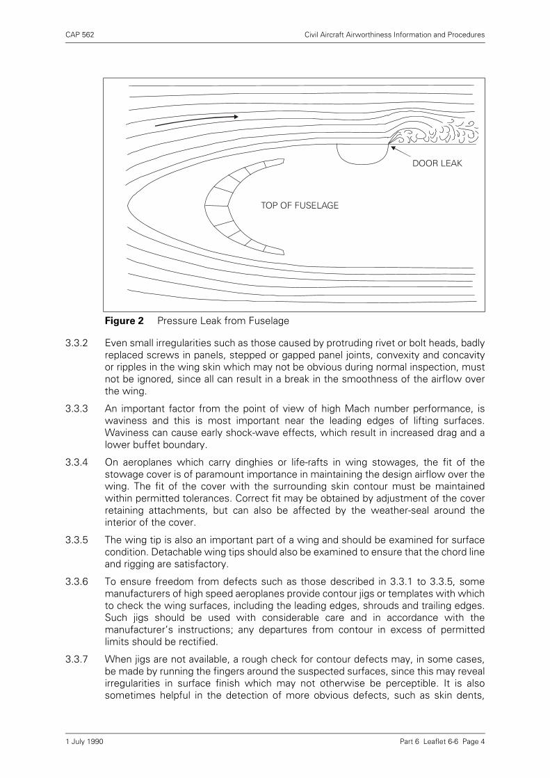
CAP 562 Civil Aircraft Airworthiness Information and Procedures
Part 6 Leaflet 6-6 Page 4
3.3.2 Even small irregularities such as those caused by protruding rivet or bolt heads, badlyreplaced screws in panels, stepped or gapped panel joints, convexity and concavityor ripples in the wing skin which may not be obvious during normal inspection, mustnot be ignored, since all can result in a break in the smoothness of the airflow overthe wing.
3.3.3 An important factor from the point of view of high Mach number performance, iswaviness and this is most important near the leading edges of lifting surfaces.Waviness can cause early shock-wave effects, which result in increased drag and alower buffet boundary.
3.3.4 On aeroplanes which carry dinghies or life-rafts in wing stowages, the fit of thestowage cover is of paramount importance in maintaining the design airflow over thewing. The fit of the cover with the surrounding skin contour must be maintainedwithin permitted tolerances. Correct fit may be obtained by adjustment of the coverretaining attachments, but can also be affected by the weather-seal around theinterior of the cover.
3.3.5 The wing tip is also an important part of a wing and should be examined for surfacecondition. Detachable wing tips should also be examined to ensure that the chord lineand rigging are satisfactory.
3.3.6 To ensure freedom from defects such as those described in 3.3.1 to 3.3.5, somemanufacturers of high speed aeroplanes provide contour jigs or templates with whichto check the wing surfaces, including the leading edges, shrouds and trailing edges.Such jigs should be used with considerable care and in accordance with themanufacturer’s instructions; any departures from contour in excess of permittedlimits should be rectified.
3.3.7 When jigs are not available, a rough check for contour defects may, in some cases,be made by running the fingers around the suspected surfaces, since this may revealirregularities in surface finish which may not otherwise be perceptible. It is alsosometimes helpful in the detection of more obvious defects, such as skin dents,
Figure 2 Pressure Leak from Fuselage
TOP OF FUSELAGE
DOOR LEAK
1 July 1990
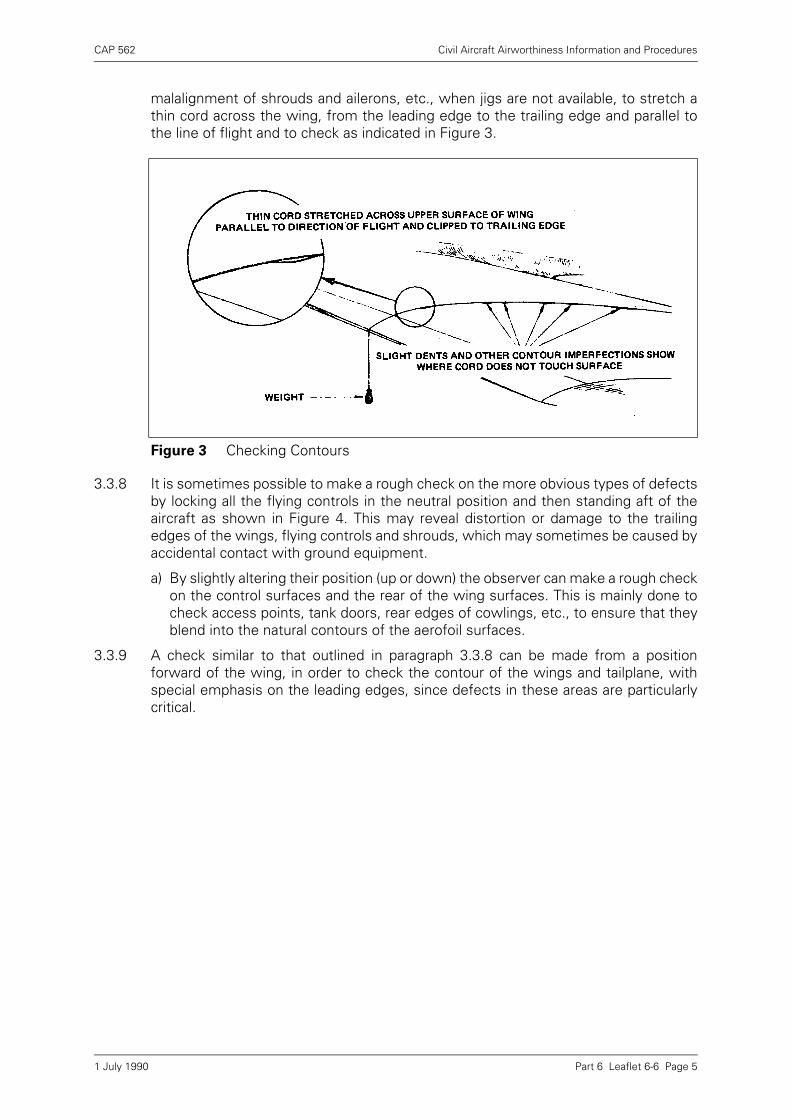
CAP 562 Civil Aircraft Airworthiness Information and Procedures
Part 6 Leaflet 6-6 Page 5
malalignment of shrouds and ailerons, etc., when jigs are not available, to stretch athin cord across the wing, from the leading edge to the trailing edge and parallel tothe line of flight and to check as indicated in Figure 3.
3.3.8 It is sometimes possible to make a rough check on the more obvious types of defectsby locking all the flying controls in the neutral position and then standing aft of theaircraft as shown in Figure 4. This may reveal distortion or damage to the trailingedges of the wings, flying controls and shrouds, which may sometimes be caused byaccidental contact with ground equipment.
a) By slightly altering their position (up or down) the observer can make a rough checkon the control surfaces and the rear of the wing surfaces. This is mainly done tocheck access points, tank doors, rear edges of cowlings, etc., to ensure that theyblend into the natural contours of the aerofoil surfaces.
3.3.9 A check similar to that outlined in paragraph 3.3.8 can be made from a positionforward of the wing, in order to check the contour of the wings and tailplane, withspecial emphasis on the leading edges, since defects in these areas are particularlycritical.
Figure 3 Checking Contours
1 July 1990

CAP 562 Civil Aircraft Airworthiness Information and Procedures
Part 6 Leaflet 6-6 Page 6
3.4 Landing Gear Doors and Fairings
Landing gear doors and fairings are often the cause of considerable drag and should,therefore, be carefully inspected in the retracted position for fit, contour and sealing.In addition, such components may be subjected to high aerodynamic loads and thepossibility exists that badly fitting or ineffectively secured panels could becomedetached from the aeroplane, with serious results. Where such components aresubjected to high aerodynamic loads the rigging procedures normally incorporate adegree of pre-loading to counter the effect of air loading.
3.4.1 In some cases it may be found necessary to simulate aerodynamic loads by loadingthe doors with weights or by use of a spring balance. This practice would indicate anyexcessive play or backlash in the mechanical linkage. In mechanically-actuated dooroperating systems, this check would be sufficient to ensure against sag in flight, butwhen the door operating system is completely or partially hydraulically operated,subsequent sag in flight may depend on the efficiency of the hydraulic system. In thelatter case every effort should be made to ensure that the relevant part of thehydraulic system is free from both internal and external leaks.
3.4.2 A landing gear door, fairing or seal which is in any way badly fitting when the door isclosed may allow air to enter the landing gear bay and eventually escape at the aft endof the door or fairing, creating considerable drag. In this case drag is caused by thefact that the air leaking into the cavity loses speed and then has to be speeded upagain as it leaks out at the other side. Figure 5 illustrates the more serious case offlow breakaway as a result of leakage, but even if this does not occur, the drag penaltymay still be quite high.
Figure 4 Checking by Observation
1 July 1990

CAP 562 Civil Aircraft Airworthiness Information and Procedures
Part 6 Leaflet 6-6 Page 7
3.5 Flaps
The undersurface of the flaps should be examined for damage caused by debristhrown up during take-off and landing and flap shrouds should be checked forsecurity, damage and distortion. The flaps should also be checked for sagging whenin the 'up' position. In the case of flaps which employ slots for improved efficiency itshould be ensured that the correct gaps are maintained.
3.6 Aileron Shrouds
The clearances between ailerons and aileron shrouds are very critical and must bechecked carefully. The shrouds should be rigid and free of any form of damage onboth bottom and top surfaces and care must be taken to ensure that no distortion ofthe shroud, or the wing skin immediately in front of the shroud has occurred, sincethis could upset the airflow over the aileron in a manner similar to that illustrated inFigure 6.
3.7 Movable Leading Edge Devices
Movable leading edge devices should be checked in the retracted position to ensurethat they conform to the contour of the main wing, particularly on the upper surface.The condition of any seals in the leading edge should also be checked, to ensure thatthere is no air leakage from the lower to the upper surface. The leading edge devicesshould also be checked in the extended position to ensure that the correct gap ismaintained between the devices and the wing.
3.8 Airbrakes/Spoilers
Airbrakes and spoilers should be checked to ensure that they are a flush fit whenretracted. Where spoilers are used for lateral control, they should be checked toensure that the 'dwell' before spoiler extension with control displacement is correct.
Figure 5 Leaks at Landing Gear Door
1 July 1990
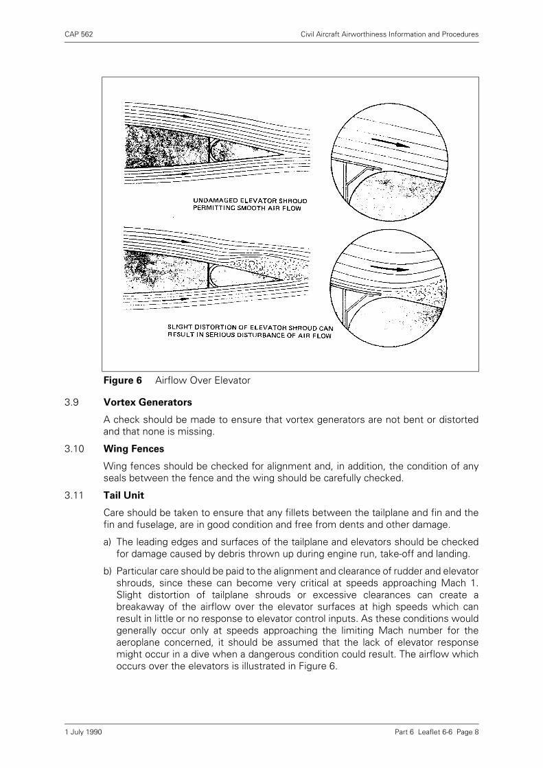
CAP 562 Civil Aircraft Airworthiness Information and Procedures
Part 6 Leaflet 6-6 Page 8
3.9 Vortex Generators
A check should be made to ensure that vortex generators are not bent or distortedand that none is missing.
3.10 Wing Fences
Wing fences should be checked for alignment and, in addition, the condition of anyseals between the fence and the wing should be carefully checked.
3.11 Tail Unit
Care should be taken to ensure that any fillets between the tailplane and fin and thefin and fuselage, are in good condition and free from dents and other damage.
a) The leading edges and surfaces of the tailplane and elevators should be checkedfor damage caused by debris thrown up during engine run, take-off and landing.
b) Particular care should be paid to the alignment and clearance of rudder and elevatorshrouds, since these can become very critical at speeds approaching Mach 1.Slight distortion of tailplane shrouds or excessive clearances can create abreakaway of the airflow over the elevator surfaces at high speeds which canresult in little or no response to elevator control inputs. As these conditions wouldgenerally occur only at speeds approaching the limiting Mach number for theaeroplane concerned, it should be assumed that the lack of elevator responsemight occur in a dive when a dangerous condition could result. The airflow whichoccurs over the elevators is illustrated in Figure 6.
Figure 6 Airflow Over Elevator
1 July 1990
CAP 562 Civil Aircraft Airworthiness Information and Procedures
Part 6 Leaflet 6-6 Page 9
4 Precautions During Maintenance
To ensure as far as possible against damage to aeroplane surfaces duringmaintenance, the precautions outlined in the following paragraphs are recommendedas the minimum necessary.
4.1 When working on the top surfaces of aeroplanes, precautions should be taken toavoid damage to the surface by scratching, etc. and suitable mats or protectivecoverings, as detailed in the appropriate manual, should always be placed in positionbefore work is commenced.
4.2 Ladders or trestles should never be rested against any part of the aeroplane andfuelling hoses should not be dragged over flying control surfaces, wing leading ortrailing edges, etc.
4.3 When removing inspection covers, panels, cowlings, fairings, etc., they should neverbe levered off, since this may damage and distort them. Leverage should not beapplied when securing or unlocking fasteners, since this may strain the fasteners tosuch an extent that the associated panel could become loose.
4.4 Cowlings, fairings, etc., should never be placed directly onto concrete floors. It isrecommended that suitable racks should be provided onto which the cowlings can beplaced immediately after removal from the aeroplane.
4.5 When a panel, fairing, etc., is removed, it should be checked to ensure that thecondition of any rubber moulding or sealing strip is satisfactory.
4.6 In certain wet take-off conditions followed by freezing, the landing gear door sealsmay sustain damage as a result of icing and these should be checked for any suchdamage.
4.7 On aeroplanes having painted surfaces, it is essential that the thickness of the paintcoating, particularly at leading edges, should be carefully controlled, since the amountof paint on the top side of a leading edge can easily influence the trim of an aircraft.This is particularly important where fillers are used to restore leading edge contoursand the finished work should always be checked with a contour jig.
4.8 All surfaces should be kept clean, since dirt, oil or mud will always adversely affectthe performance of the aeroplane.
4.9 When changing control surfaces or other aerofoil components, care should be takento ensure that the new components fitted are in correct aerodynamic alignment withthe surrounding structure, since the slight differences which can occur in nominallysimilar components, as a result of manufacturing tolerances, could affect the trim orperformance of the aeroplane.
1 July 1990

INTENTIONALLY LEFT BLANK

CAP 562 Civil Aircraft Airworthiness Information and Procedures
Part 6 Leaflet 6-7 Page 1
Leaflet 6-7 Assembly and Maintenance of Critical Bolted
Joints
1 Introduction
1.1 This Leaflet gives guidance on the recommended assembly procedure for criticalbolted joints and on the extent to which inspection can verify that designrequirements have been met. Guidance is also given on the inspections necessaryduring maintenance and overhaul to ensure the continued effectiveness of the joint.
1.2 In the context of this Leaflet the term 'critical bolted joint' is used to describe anybolted joint or attachment where stress levels are high and where inadequateassembly techniques could result in fatigue failure. Examples of critical bolted jointsare spar joints, tailplane attachments, wing attachments and engine mountingstructure.
1.3 Where specialised procedures or techniques are specified for the preparation orassembly of a critical bolted joint, the manufacturer’s published procedures should bereferred to and their recommendations observed.
1.4 Related CAAIP Leaflets:
2–11 Torque Loadings
4–7 Magnetic Flaw Detection
1.5 The subject headings are as follows:
2 Assembly Procedure
2.1 During the initial assembly of a joint, checks should be made to ensure that thecomponent parts are protected against corrosion, that the edges of holes are de-burred, chamfered or radiused as appropriate and that mating surfaces are free fromswarf or other foreign matter.
Paragraph Subject Page
1 Introduction 1
2 Assembly Procedure 1
3 Jointing Compound 3
4 Tightening of Bolts 4
5 Inspection of Bolted Joints 6
6 Locking 8
1 July 1990

CAP 562 Civil Aircraft Airworthiness Information and Procedures
Part 6 Leaflet 6-7 Page 2
2.2 Before bolts are inserted it must be ensured that parts are correctly assembled andthat no mis-alignment is present. Where one component is a fork-type fitting, a slidingbush may be fitted in one arm of the fork; provided that a clearance is maintainedbetween the head of the bush and the fork during tightening of the assembly bolt(Figure 1), stressing of the fork fitting will be avoided. In other cases a good fit isobtained by selective assembly or by fitting shims or washers; if play is present in thistype of joint the tightening of attachment bolts will induce a stress and weaken thefork fitting.
2.3 In some instances assembly instructions may require good bearing contact betweenthe mating surfaces of the various components and also on the pressure faces of boltheads and nuts. Tapered bolt holes should be checked by applying engineers blue tothe hole and lightly rotating the bolt, while flat surfaces should be checked on asurface table, or by the use of engineers blue or feeler gauges during a trial assembly.Poor bearing surfaces should then be corrected by light lapping. Each hole should bechecked using its own assembly bolt.
2.4 In some instances the surfaces of bolt holes in critical locations are stressed toprevent crack propagation and fatigue failure. Plastic deformation of the materialsurrounding the holes is produced by some form of broaching, such as the use of aninterference fit mandrel, before the assembly bolt is fitted. In the case of taperedbolts in aluminium alloy components the hole is reamed until the bolt stands proud ofthe surface by a specified amount then, during final tightening, the tapered boltexpands the hole and induces compressive stress in the hole surface.
2.5 When performing operations such as drilling, reaming, lapping, etc., prior to finalassembly of a joint, it is essential that the assembly is trued and held securely inposition by clamps, slave bolts etc. This will prevent the ingress of swarf betweenfaying surfaces and ensure that the joint is retained in this position when the jointbolts are finally inserted. Greater joint accuracy will be ensured if the joint bolts areinserted in sequence on each side of the joint immediately after each bolt fittingoperation.
2.6 Parallel holes which have been opened to full size during assembly may be checkedfor size by means of plug gauges, but in certain instances, particularly when
Figure 1 Fork Fitting with Sliding Bush and Anti-Rotation Retainer when Applicable
1 July 1990
CAP 562 Civil Aircraft Airworthiness Information and Procedures
Part 6 Leaflet 6-7 Page 3
interference fits are required, the use of more specialised measuring equipment suchas a pneumatic bore gauge may be necessary.
2.7 Careless fitting or assembly can considerably reduce the fatigue life of a joint. A burron a bolt, or a piece of swarf left in a hole can scratch the surface of the hole and resultin the concentration of stresses. To prevent the scoring of bolts and holes thoroughcleanliness must be maintained and if shouldered bolts are used a 'bullet' should befitted to protect the thread and provide a lead-in for the bolt shank. Lubrication of thebolts is usually recommended and the lubricant (or sealant) should be kept in a sealedcontainer to prevent contamination when not in use. (See paragraph 3).
2.8 It will be appreciated that many highly stressed joints will require no hand fitting. Thecomponents may be jig built to very fine tolerances which obviate most of the fittingprecautions outlined in the preceding paragraphs. However, a high standard ofcleanliness and care in handling the components is still necessary if design strengthis to be maintained.
2.9 Where joints or fittings have more than one bolt, progressive tightening should becarried out in order to prevent stresses being induced. In some cases the finaltightening sequence will be stipulated on the appropriate drawing. Nuts should befitted finger-tight then progressively tightened to the appropriate pre-load value, butnew parts may require bedding-in by first tightening to half the pre-load, slackening,then finally tightening in accordance with the manufacturer’s recommendations.
3 Jointing Compound
3.1 There are a number of different compounds in use which are selected according tothe type of joint, the probable frequency of disassembly, the material involved, themethod of assembly, the protective treatments applied and the conditions ofoperation.
3.2 Pigmented varnish jointing compound to DTD 369, or other compounds covered byspecification DTD 900, are frequently used to prevent scuffing and corrosion in jointsand cold-setting polysulphide synthetic rubber materials are often used for jointsealing. Other materials may be specified for use in particular locations and referenceshould be made to the appropriate aircraft manual for instructions regarding their use.
3.3 In joints where hard-setting compounds are specified, precautions should be taken toensure that the joint is tightened whilst the compounds are still wet, otherwisedimensional tolerances may be seriously affected if the compounds become drybefore the joint is tightened.
3.4 Care should be taken to ensure that only the specified jointing compound is used,since, for example, that complying with DTD 369 is not suitable where temperaturesin the vicinity of the joint may exceed 200°C, whilst hard-setting compounds areunsuitable in areas where vibration may occur.
3.5 Jointing compounds will give unsatisfactory results if kept in open containers whichallow them to become semi-dry before application and to ensure consistent resultsfrom occasional use are often supplied in squeeze-tubes.
3.6 Sealants are usually supplied in twin-pack form and mixing instructions should befollowed carefully. Once mixed the sealant starts to harden and final assembly of ajoint should be completed within a specified application time. Sealant which is notused within its application time must be discarded.
1 July 1990
CAP 562 Civil Aircraft Airworthiness Information and Procedures
Part 6 Leaflet 6-7 Page 4
4 Tightening of Bolts
4.1 The tension (pre-load) applied to a bolt during tightening should be greater than thehighest stress likely to be encountered in service. The most efficient joint would beobtained by tightening each bolt to its yield point but, due to manufacturing tolerancesand other variables, the practice would be dangerous to apply; in addition, each boltcould only be used once. A number of other ways of preloading bolts have beendevised and although these may result in a less-than-optimum tension, have provedsatisfactory in service.
4.2 Under-tightening of bolts in highly stressed joints may, when load is applied, result inlack of contact or rigidity between the separate parts of the assembly. Wherealternating or fluctuating loads are applied to such joints early fatigue failure mayoccur. Conversely, over-tightening is likely to cause immediate failure of the bolts ordistortion of one or more parts of the assembly.
4.3 The general problem of applying a specified pre-load to a bolt is also affected by theneed to line up split-pin holes. Unless the bolt pre-drilling suits the joint and nutdimensions, or the bolt is drilled after tightening, the applied pre-load will beinaccurate to the extent of the nut adjustment. In some applications this inaccuracymay be acceptable, but in others the selection of alternative nuts or washers may berecommended.
NOTE: For some installations the bolt head is indexed and must be maintained in therequired position by an anti-rotation retainer (see Figure 1).
4.4 Torque Loading
The most common method of pre-loading is by applying a specified torque to the nutduring tightening. Laboratory tests are carried out to ascertain an appropriate torqueloading for any particular application, taking into account the type of thread, bolt andnut materials, manufacturing tolerances, type of anti-corrosive treatment and type oflubricant. This loading is applied by means of a torque wrench and results in areasonably consistent pre-load being applied to the bolt. The use of torque wrenchesis covered in Leaflet 2–11.
4.5 Pre-load Indicating Washers
The value of the pre-load applied to a fastener by means of a torque wrench may varyconsiderably and, because of this, specified torque loadings are usually low comparedwith the actual strength of the fastener. In certain critical bolted joints themanufacturer may consider that more accurate clamping is required and specify theuse of pre-load indicating (PLI) washers.
1 July 1990
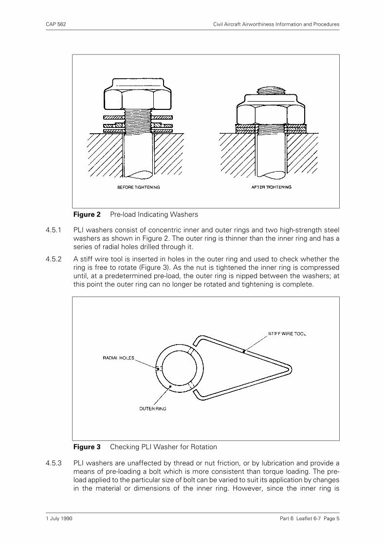
CAP 562 Civil Aircraft Airworthiness Information and Procedures
Part 6 Leaflet 6-7 Page 5
4.5.1 PLI washers consist of concentric inner and outer rings and two high-strength steelwashers as shown in Figure 2. The outer ring is thinner than the inner ring and has aseries of radial holes drilled through it.
4.5.2 A stiff wire tool is inserted in holes in the outer ring and used to check whether thering is free to rotate (Figure 3). As the nut is tightened the inner ring is compresseduntil, at a predetermined pre-load, the outer ring is nipped between the washers; atthis point the outer ring can no longer be rotated and tightening is complete.
4.5.3 PLI washers are unaffected by thread or nut friction, or by lubrication and provide ameans of pre-loading a bolt which is more consistent than torque loading. The pre-load applied to the particular size of bolt can be varied to suit its application by changesin the material or dimensions of the inner ring. However, since the inner ring is
Figure 2 Pre-load Indicating Washers
Figure 3 Checking PLI Washer for Rotation
1 July 1990

CAP 562 Civil Aircraft Airworthiness Information and Procedures
Part 6 Leaflet 6-7 Page 6
compressed during tightening it can only be used once and if slackened must bereplaced.
4.5.4 Due to the method of tightening, PLI washers can only be used with self-locking nuts.
4.6 Shear Type Fasteners
A number of proprietary fasteners are available which permit a reasonably accuratepre-load to be applied to a bolt without the use of torque wrenches. The nut normallyused has an upper hexagonal wrenching portion, separated from the main nut by adeep groove. The hexagon portion shears off during tightening when a predeterminedclamping force is reached.
4.7 Bolt Extension
An accurate method of pre-loading which, unfortunately, cannot often be used inairframe applications for reasons of inaccessibility, is the measurement of boltextension. The bolts are tightened until a specified extension has taken place, asmeasured by means of a micrometer or similar instrument.
4.8 Dished Washers
These washers are sometimes used on dynamically loaded structures. The washersconsist of circular discs of constant thickness and have an initial 'dish' raising thecentre, so that when nipped they act as a spring of very high rating and willaccommodate a certain amount of stretch in the bolt shank, or bedding-in of the head.By variation of the thickness, outer diameter and height, a wide variety of loaddeflection characteristics can be obtained, but unlike pre-load indicating washers,there is no reliable way of ensuring when optimum tightness has been reached.
4.9 Standard Spanners
The use of standard spanners is seldom recommended as the only method oftightening a critical bolted joint. British Standard 192 gives the lengths of spanners tobe used with the different sizes of nuts and this leverage is usually adequate forgeneral engineering work. It would, however, be impossible for even a skilledoperator to apply a consistent amount of pre-load to a variety of bolt sizes. Areasonably accurate torque loading could be applied, in emergency, by using, forexample, a double ended ring spanner and a spring balance, with the direction of pullat 90° to the spanner. The balance reading multiplied by the spanner length wouldgive the torque loading applied.
NOTE: In certain installations the material of the component dictates use of special tools orprotection from contact with standard tools.
5 Inspection of Bolted Joints
5.1 Unless bolts are extracted, visual examination is unlikely to reveal the faults which areusually associated with the beginning of cracks, fretting, corrosion etc. However,visual inspection is important as a means of checking that there are no indications ofmovement in the joint and that the external protective treatment is in good condition.
5.2 At the periods specified in the approved Maintenance Schedule, bolts should beextracted to enable a detailed examination to be made. Although this can be donemost conveniently if the joint is broken down during major overhaul, on some aircraftone or more bolts may be required to be removed from critical joints at more frequentintervals. Whenever bolts are to be removed from these joints it will be necessary tosupport the surrounding structure in such a way as to remove the loads normallytaken by the joint. The supports should be adjusted so that no residual loads are
1 July 1990
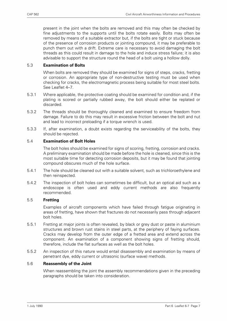
CAP 562 Civil Aircraft Airworthiness Information and Procedures
Part 6 Leaflet 6-7 Page 7
present in the joint when the bolts are removed and this may often be checked byfine adjustments to the supports until the bolts rotate easily. Bolts may often beremoved by means of a suitable extractor but, if the bolts are tight or stuck becauseof the presence of corrosion products or jointing compound, it may be preferable topunch them out with a drift. Extreme care is necessary to avoid damaging the boltthreads as this could result in damage to the hole and induce stress failure; it is alsoadvisable to support the structure round the head of a bolt using a hollow dolly.
5.3 Examination of Bolts
When bolts are removed they should be examined for signs of steps, cracks, frettingor corrosion. An appropriate type of non-destructive testing must be used whenchecking for cracks, the electromagnetic process being suitable for most steel bolts.See Leaflet 4–7.
5.3.1 Where applicable, the protective coating should be examined for condition and, if theplating is scored or partially rubbed away, the bolt should either be replated ordiscarded.
5.3.2 The threads should be thoroughly cleaned and examined to ensure freedom fromdamage. Failure to do this may result in excessive friction between the bolt and nutand lead to incorrect preloading if a torque wrench is used.
5.3.3 If, after examination, a doubt exists regarding the serviceability of the bolts, theyshould be rejected.
5.4 Examination of Bolt Holes
The bolt holes should be examined for signs of scoring, fretting, corrosion and cracks.A preliminary examination should be made before the hole is cleaned, since this is themost suitable time for detecting corrosion deposits, but it may be found that jointingcompound obscures much of the hole surface.
5.4.1 The hole should be cleaned out with a suitable solvent, such as trichloroethylene andthen reinspected.
5.4.2 The inspection of bolt holes can sometimes be difficult, but an optical aid such as aendoscope is often used and eddy current methods are also frequentlyrecommended.
5.5 Fretting
Examples of aircraft components which have failed through fatigue originating inareas of fretting, have shown that fractures do not necessarily pass through adjacentbolt holes.
5.5.1 Fretting at major joints is often revealed, by black or grey dust or paste in aluminiumstructures and brown rust stains in steel parts, at the periphery of faying surfaces.Cracks may develop from the outer edge of a fretted area and extend across thecomponent. An examination of a component showing signs of fretting should,therefore, include the flat surfaces as well as the bolt holes.
5.5.2 An inspection of this nature would entail disassembly and examination by means ofpenetrant dye, eddy current or ultrasonic (surface wave) methods.
5.6 Reassembly of the Joint
When reassembling the joint the assembly recommendations given in the precedingparagraphs should be taken into consideration.
1 July 1990

CAP 562 Civil Aircraft Airworthiness Information and Procedures
Part 6 Leaflet 6-7 Page 8
6 Locking
Locking devices must be sufficiently effective to prevent loosening or turning of thethreaded parts and they should be fitted as specified in the relevant drawing ormanual. Most locking devices may only be used once, but those which can be re-usedshould be checked for effectiveness before being refitted.
1 July 1990

CAP 562 Civil Aircraft Airworthiness Information and Procedures
Part 6 Leaflet 6-8 Page 1
Leaflet 6-8 Glass Windscreen Assemblies
1 Introduction
This Leaflet gives guidance on the installation and maintenance of aircraft glasswindscreen assemblies of both the simple and complex electrically heated type. Asthe assemblies fitted to different aircraft vary considerably, the information given inthis Leaflet should be read in conjunction with the Maintenance Manuals and theapproved Maintenance Schedule for the type of aircraft concerned. The CAARequirements regarding tests on pressure panels are given in Chapter D3–7 andACJ 25.775(d) of British Civil Airworthiness Requirements.
2 Glass
Glass is a hard, brittle material having the outstanding quality of transparency. Toovercome brittleness but to leave transparency unimpaired is the main object of themanufacture of safety glass as used for aircraft windscreens. Examples ofspecifications which meet the requirements are DTD 218 Laminated Safety Glass,DTD 869 Laminated Safety Glass, High Light Transmission, DTD 761 Safety GlassWindscreen, Gyro Sight Quality and DTD 5576A Electrically Heated Laminated SafetyGlass.
2.1 Characteristics of Glass
Glass, unlike metals, is non-crystalline. When heated or cooled it shows no sharpchange in physical properties and has no definite melting point, but at about 600°Cplate and sheet glass begin to flow under their own weight.
2.1.1 Glass may be broken by loading in various ways, e.g. impact, tension, twist,compression or shear and fracture will occur under any type of loading whendeformation has produced the necessary tensile stress.
2.1.2 The breaking strength of glass is greatly influenced by five factors:
a) Heat treatment (paragraph 2.2).
b) Length of time of loading (paragraph 2.3).
c) The rate of application of a load (paragraph 2.4).
d) The condition of the surfaces and edges (paragraph 5).
e) Method of installation (paragraph 3.2).
2.2 Heat Treatment
2.2.1 Annealing
After manufacture glass is cooled very slowly so that stress set up during the formingof the sheet may dissipate. If this were not the case, built-in tensile stress wouldweaken the glass to such an extent that it could break spontaneously. When glass ofgreater strength than annealed glass is required, a tempered glass is used.
2.2.2 Tempered Glass
The glass is heated to some point within the range in which it becomes soft and thenthe surfaces are quickly cooled by blasts of compressed air. This chills and hardensthe outer surfaces whilst the inside is still hot and contracting, thus putting the outer
1 July 1990
CAP 562 Civil Aircraft Airworthiness Information and Procedures
Part 6 Leaflet 6-8 Page 2
'skins' of the glass in a state of compression, resulting in a considerable increase instrength.
a) The main drawback of tempering is that the glass will break up into tiny particleswhen fractured (the greater the degree of tempering the smaller will be the particlesize) thus seriously obstructing vision.
b) In the United Kingdom, glass which has been tempered to give maximum strengthis termed 'toughened glass' (e.g. Type 1 of DTD 5576A). The term 'strengthenedglass' (e.g. Type 2 of DTD 5576A) is used to indicate glass which has beentempered to a lesser degree than toughened glass. Although less strong thantoughened glass it has the advantage of larger particle size should fracture occur.
c) Because of the physical nature of tempered glass it cannot be filed, drilled ortrimmed in any way, therefore any adjustments required during fitting must, ofnecessity, be done on the mounting frame. Great care is necessary when fittingthe glass to prevent damage, for example chipping. Scratches, chips, flaws andother surface defects weaken glass very considerably and on this score aloneevery effort must be made to avoid such defects, particularly at the edges of theglass (see paragraph 5).
2.3 Fatigue
Cyclic fatigue of toughened glass at commonly used stress level, is effectively non-existent.
2.4 Safety Factors
The safety factors required on glass components are very much higher than for othermaterials used in aircraft manufacture, because of the loss of strength with durationof load, scatter in strength inherent in glass, thickness tolerances and high notchsensitivity.
3 Windscreen Design
The design of windscreens varies considerably according to the type of aircraft towhich they are fitted, the extent of de-misting and impact strength required and alsoon whether an electrical method of anti-icing is to be used. The details given in thefollowing paragraphs are of a general nature, outlining some design features of typicalwindscreen assemblies.
3.1 Windscreens are of laminated manufacture and in general can be considered asbelonging to one of two categories,
a) the simple windscreen, usually fitted to non-pressurised aircraft having limitedperformance, and
b) the electrically-heated panel windscreen fitted to pressurised aircraft with all-weather capability.
3.1.1 Simple Windscreens
A panel is usually made up of two pre-formed and pre-tempered glass layers or plies,each of which is bonded to a sandwiched sheet or ply of reinforcing material termedthe 'interlayer'. The suitability of a material for use as an interlayer depends on anumber of factors, the most important of which are its ability to withstand impact, toprevent breakage into dangerous fragments and to prevent detachment of suchfragments from the inner surface of a panel. The material normally used for the
1 July 1990

CAP 562 Civil Aircraft Airworthiness Information and Procedures
Part 6 Leaflet 6-8 Page 3
interlayer is polyvinyl butyral (plasticised with dibutyl sebacate or triethylene glycol de-hexoate), generally referred to as vinyl.
a) The vinyl and glass layers are bonded by the application of pressure and heat, thetemperature being considerably less than that required for tempering the glass andbelow the temperature at which vinyl would flow. The bond is achieved withoutthe use of a cement as vinyl, after laminating, has a natural affinity for glass.
3.1.2 Electrically Heated Windscreens
These windscreens are used on pressurised aircraft to prevent the formation of iceand mist on the panels and to improve the impact resistance of the windscreen panelat low temperatures (see Appendix 2 of Chapter D4–2 of British Civil AirworthinessRequirements or ACJ 25.775(d)). The physical properties of vinyl vary considerablywith changes in temperature. Considering a range of ambient temperatures normallyencountered under flight operating conditions, the vinyl would be brittle in the lowerpart of the range and plastic in the upper part. Since the desired impact resistancecharacteristics of a windscreen depend to a large degree on the plasticity of the vinylinterlayer, it follows that impact resistance is dependent on interlayer temperature.
a) The panels are of special laminated manufacture containing a resistance typeheating element in the form of a film deposited on the inner surface of the outerglass layer. The heating element is supplied with power from the aircraft electricalsystem via terminals on the panel frame and by busbars 'fired' onto a glass layerat the top and bottom edges of the element. The temperature of the panel iscontrolled by a temperature-sensing element laminated into the panel andconnected to an automatic control unit.
b) The windscreens in certain of the larger types of aircraft consist of up to seventransparent layers made up of glass, vinyl, acrylic plastic and polyester material. Ina typical assembly, three thin vinyl interlayers are employed and they sandwichtwo layers of thick stretched acrylic plastic. Together the acrylic layers providemost of the windshield structural integrity. The outer layer of the windscreen is athin, chemically toughened and abrasive-resistant glass layer and its inner face iscovered with the heating element which is supplied with power from busbars atthe top and bottom of the windscreen. Two sensing elements for automatictemperature control and an overheat sensing element are laminated into the panel.Only one of the control elements is used; the other serves as a spare. The innerlayer of the windscreen assembly is made of an abrasion-resistant polyestermaterial.
c) There are two types of heating elements in general use; namely, tin oxide and goldfilm, the latter complying with specifications DTD 5576A. These panels are brieflydescribed in the following paragraphs.
i) Tin Oxide Film Panels. In this type of panel, the heating element is producedby spraying with a flame gun a coating (0·000002 inch thick) of tin oxide at1000°C on the inner surface of the outer glass layer which is then bonded to thevinyl interlayer.
ii) Gold Film Panels. In these panels a combined film of gold and metal oxide isused as the heating element. The film is electrically-deposited on the surface ofthe glass in a vacuum chamber.
3.2 Windscreen Attachment Methods
There are several methods of attaching windscreen assemblies dependent on thetype employed. The method frequently adopted for simple type windscreens is theone generally referred to as 'Friction Mounting'; it is illustrated in Figure 1. The
1 July 1990

CAP 562 Civil Aircraft Airworthiness Information and Procedures
Part 6 Leaflet 6-8 Page 4
periphery of the panel is clamped between metal glazing strips and the fuselageframe by a series of bolts. To avoid damaging the glass and to ensure that the jointwill be watertight, a suitable lining, usually in the form of a special rubber strip ormoulding, is fitted or bonded to the structure.
3.2.1 The impact strength of a laminated panel is based on the ability of the interlayer tostretch and deform and thus absorb the shock load, assuming that the impact is greatenough to shatter the glass layers. Under such conditions it is essential that the vinylinterlayer be held securely around the edges of the panel. It is for this reasontherefore, that panels designed to resist high impact loads and in particular electricallyheated panels, are secured to the windshield frames by bolts passing through theedges of the panels rather than relying on the clamping action shown in Figure 1.
a) The vinyl interlayer of this type of windscreen is generally thicker than that used inordinary laminated windscreens and it is extended beyond the periphery of theglass layers. In windscreens employing layers of acrylic plastic this applies to theselayers also. A further refinement in the design is an aluminium alloy reinforcingstrip, which is in the form of a frame and is embedded in the vinyl. This strip,together with aluminium alloy inserts in each of the bolt holes, assists inpreventing the vinyl from deforming at the edges under pressurisation loads andalso when tightening bolts during installation. A typical assembly is shown inFigure 2.
Figure 1 Friction Mounting
Figure 2 Extended Interlayer Method
1 July 1990

CAP 562 Civil Aircraft Airworthiness Information and Procedures
Part 6 Leaflet 6-8 Page 5
4 Installation
The installation of windscreen panels must be in accordance with the procedurespecified in the relevant aircraft Maintenance Manual. The information given in thefollowing paragraphs is of a general nature and is intended as a guide.
4.1 Before installation, panels should be carefully checked for any sign of damage suchas scratches and chips (see paragraph 5.1.2 and 5.1.3). The frames must be clean andseals, where fitted, must be undamaged. Frame mounting faces should be inspectedfor flatness and freedom from distortion.
NOTE: Cleaning agents must be of the type specified in the relevant aircraft MaintenanceManual and should not be applied indiscriminately to windscreens and surroundingstructure. Incorrect cleaning agents may attack the interlayer and causedelamination.
4.2 Where specified, clearances between panels and fuselage structure must bechecked to ensure that they are within limits. In some instances, particularly forsimple type windscreens, the edges of panels are rebated (see Figure 1) toaccommodate the glazing strips and specified clearances between strips and raisedportions of panels must be maintained.
4.3 The condition of pressure and weather seals should be examined before installationof a panel and, where necessary, replaced or repaired in the manner specified for theparticular type of aircraft.
4.4 In installations requiring a fluid plastic compound for sealing purposes, the compoundmust be applied in a uniform layer and of the correct thickness to form a gasketbetween windscreen and fuselage frames, the required thickness being obtained bybolting a windscreen to its respective frame. In some cases a bedding-down templateis provided for this purpose.
NOTE: The compound must be left to cure for the relevant time period before finallytightening the attachment bolts.
4.5 A silicone grease (sometimes referred to as a release agent) of the type specified inthe appropriate aircraft Maintenance Manual, should be applied to the matingsurfaces of windscreen frames to form a silicone film which is non-adhesive topressure and weather seals and facilitates subsequent removal of panels.
NOTE: In some types of aircraft, a preformed strip or gasket may also be fitted to serve thispurpose.
4.6 On electrically heated windscreen panels fitted to certain types of aircraft, a codenumber is etched in the corner of the glass near the busbar terminals to indicate theheating element resistance. As it is possible for the number to be covered when thepanel is installed, details should be noted before installation to ensure correct heatingcircuit connections.
4.7 In aircraft in which a standby magnetic compass is located on a structural supportbetween two windscreen panels, care must be taken to ensure that the panelattachment bolts in the vicinity of the compass position are of non-magnetic material.After installation, a check compass swing must be carried out to prove the accuracyof the standby compass, with current to the windscreens switched both 'on' and 'off'.
4.8 Attachment bolts and nuts should be coated with a compound to provide a seal ateach of the bolt holes. Where compounds are specified, details of types and methodsof use are contained in the relevant aircraft Maintenance Manual.
4.9 During the initial stages of fitting attachment bolts, the panel should always beadequately supported to prevent it resting on the bolts thus preventing the
1 July 1990

CAP 562 Civil Aircraft Airworthiness Information and Procedures
Part 6 Leaflet 6-8 Page 6
countersunk heads from seating correctly. Locating keys are provided for thispurpose in some types of aircraft and they should be used in the manner specified.When installing windscreens of the extended interlayer type, it is important to ensurethat the specified clearance exists between fixing holes and bolts.
4.10 Attachment bolts should be tightened evenly and in a staggered sequence ensuringthat the panel is not distorted and that bolt torque loadings are as specified.
4.11 Cable terminals on electrically heated windscreen panels should be suitably protectedagainst damage. After installation the anti-icing system cables should be connectedto their respective terminals, identified in accordance with the relevant wiring diagramand the heating system checked for correct functioning.
4.12 After installation of a windscreen panel in a pressurised cabin type aircraft and elapseof the requisite curing time for sealing compounds, a cabin pressurisation and leakrate test should be carried out if prescribed in the relevant aircraft MaintenanceManual.
5 Inspection and Maintenance
The information given in the following paragraph is of a general nature and should beread in conjunction with the Maintenance Manuals and approved MaintenanceSchedules for the aircraft concerned.
5.1 Damage
Panels should be inspected for defects and any signs of damage such asdelamination, chipping and cracking of glass layers. The following brief descriptivedetails are intended as a guide to this type of damage and other defects which mayoccur.
5.1.1 Delamination
This is a defect which can occur in laminated windscreens characterised by theseparation of a glass layer from the vinyl interlayer. Delamination should not beconfused with deliberate stress-relieving edge separation of panels which issometimes employed. In such cases a parting medium is used, introducing aseparation penetrating the edges of the panel assembly to a distance of 6 mm to25 mm (0·25 inch to 1 inch) and giving a yellowish or brownish appearance at theedges.
a) Defective delamination has characteristics that tend to divide it into the followingmain types and resulting from different types of stress at the glass/vinyl interface.
i) Clear (or cloudy). Of the two types, delamination is apt to be clear. Howevercloudy delamination will result if moisture penetrates the delaminated area. Indoubtful cases delamination can be confirmed by carrying out a reflection testby means of a flaw detector using a light beam. The beam is directed onto thesurface of the windscreen and produces two sharply defined lines on a ground-glass screen representing the top and bottom surfaces of the windscreen. Anydelamination present will produce an additional line and its proximity to eitherof the other lines is helpful in deciding which of the layers has separated.
ii) Rough-edge. This is characterised by its irregular, sharp or jagged boundary. Itmay develop long finger-like projections if, during the course of delaminationthe parting between vinyl and glass is not uniform.
1 July 1990

CAP 562 Civil Aircraft Airworthiness Information and Procedures
Part 6 Leaflet 6-8 Page 7
iii) Smooth-edge. Smooth-edge delamination advances with a smooth boundary.It does not have rough or jagged areas within it, nor indications of internal cracksor chips.
b) A small amount of delamination is permitted on most aircraft but details of thepermissible extent and any limits concerned with aircraft flight operations, e.g.flights under pressurised conditions, should be obtained from the relevant aircraftMaintenance Manual and Flight Manual.
5.1.2 Scratches
Scratches are defects in the surface of a panel and every effort must be made to avoidthem. They are normally more prevalent on the outer surface where windshieldwipers are indirectly the primary cause. Any dust or grit trapped by a wiper blade canimmediately become an extremely effective cutting device as soon as the wiper is setin motion. Wiper blades must therefore be maintained in a clean condition and shouldonly be operated when the windscreens are wet.
a) On the basis of severity, scratches may be classified as hairline, light and heavy.
i) Hairline Scratches. A hairline scratch can be seen but is difficult to feel with afingernail. It can be caused by wiping the glass with a dry cloth. To avoid hairlinescratches, the glass should be cleaned with a mild detergent and water, usinga soft brush or clean, soft cotton cloth, followed by drying with a clean, softcotton cloth.
ii) Light Scratches. A light scratch is less than 0·254 mm (0·010 inch) deep andcan be felt with a fingernail. This type of scratch ordinarily has few edge chips.
iii) Heavy Scratches. A heavy scratch is 0·254 mm (0·010 inch) or more in depthand can be readily felt with a fingernail. This type of scratch is apt to showextensive edge chipping.
b) If the integrity of a panel is not suspected and provided visibility is not seriouslyaffected, scratches are permissible within limits detailed in the relevant aircraftMaintenance Manual.
c) Scratches can be removed by polishing, but due to an uneconomic time factor,possible optical distortion and problems of assessing optical standards acceptablein the ultimate operational situations, it is recommended that a panel assembly bereturned to the manufacturer and replaced by a serviceable assembly.
5.1.3 Chipping
Chips are flakes or layers of glass broken from the surface which can occur if theexterior surfaces of a panel are struck by a sharp object. The inner surfaces of alamination of the panel may also chip in unheated areas, as a result of high internalstresses. There are two types of chips: conchoidal and V-shaped. Conchoidal chipsare usually circular or curved in shape with many fine striations that follow the outlineof the outer edge. V-shaped chips are sharp and narrow, the 'V' appearing topropagate toward the interior of the glass. Visibility through chipped areas of awindscreen panel is usually poor.
a) Chips occurring at the inner surfaces of glass panels are critical because theexisting condition may result in cracking or shattering of a pane, or in the case ofan electrically heated windscreen, destruction of the resistance heating film.These chips are usually associated with rough-edge delamination (see paragraph5.1.1).
1 July 1990

CAP 562 Civil Aircraft Airworthiness Information and Procedures
Part 6 Leaflet 6-8 Page 8
5.1.4 Cracks
These are serious defects which, depending on the type of glass and the formationand propagation of the cracks, may result in considerable strength reduction of thewindscreen and effects on visibility varying from slightly impaired to completeobscurity. In annealed glass the damage may take the form of single cracks, or cracksforming an irregular criss-cross pattern. The more usual result of damage tostrengthened glass is the formation of cracks spreading radially from the point ofdamage and in these cases, vision is impaired but not completely obscured. Cracksin a toughened glass form a pattern defined as shattering, a defect resulting inconsiderable reduction in strength and loss of vision. A windscreen having such adefect should be removed and replaced by a serviceable assembly.
a) The extent to which cracks are permitted, limitations on aircraft operation and theaction to be taken in order to rectify the defects, may vary between aircraft types.Details are given in the relevant aircraft Maintenance Manual and Flight Manualand reference must therefore always be made to these documents.
5.1.5 Vinyl Rupture
Vinyl rupture consists of a failure across the section of vinyl at the inner edge of themetal insert (Figure 2) and necessitates changing the panel.
5.1.6 Vinyl 'Bubbling'
Small bubbles occurring within the vinyl interlayer of electrically heated windscreensare not a delamination nor are they structurally dangerous. They are usually due tooverheating conditions, being formed by a glass liberated by the vinyl. They need notbe a cause for windscreen replacement unless vision is seriously impaired. Theirpresence, however, may indicate a defective window heat control system whichshould be rendered inoperative pending rectification.
5.1.7 Discolouration
Electrically heated windscreens are transparent to direct light but they normally havea distinctive colour when viewed by reflected light. This apparent discolouration is dueto the resistance heating film and it may vary slightly between windscreens. Onlyblack or brown discolouration, when viewed normal to the surface, should beregarded as a possible defect necessitating removal of the windscreen andreplacement by a serviceable one. The cause of such discolouration may be a burnoutof the heating film or a carbon deposit between a busbar and the heating film due tooverheating.
5.2 Sealants
Weather sealants provided around the periphery of windscreens must be inspectedfor evidence of erosion, lack of adhesion, separation or holes. The obvious purpose ofmaintaining an effective weather sealant is to protect the windscreens againstmoisture entry and the delamination or electrical problems associated with moisturepenetration. When new sealant is required, the damaged material should beremoved, the area cleaned and new material applied in the manner prescribed in therelevant aircraft Maintenance Manual.
NOTE: Damaged material should always be removed with a plastic tool that will fit, withoutbinding, in the gap between windscreen and frame. The use of a metal tool isinadvisable, as this could damage the glass or vinyl interlayer.
1 July 1990
CAP 562 Civil Aircraft Airworthiness Information and Procedures
Part 6 Leaflet 6-8 Page 9
5.3 Cleaning of Windscreens
Windscreens should be washed regularly with warm water and mild detergent, usinga clean, soft cloth or cotton wool pad; after washing the panels should be rinsed anddried with a clean, soft cotton cloth. Scratching of the glass must be avoided.
5.3.1 Some aircraft manufacturers recommend the use of a proprietary detergent which isalso suitable for the surrounding aircraft structure and therefore to some extentsimplifies cleaning operations; it is important that only the detergent specified is usedand that the prescribed proportion of detergent to water is observed.
5.3.2 Grit, dirt, etc., should be removed at regular intervals from recesses, for example,where the panel joins the frame, to prevent it being picked up by the cleaning clothsand causing scratching. The accumulation of cleaning and polishing materials inrecesses must be avoided.
6 Storage
Extreme care is necessary during transportation, storage and handling ofwindscreens to prevent damage. It is recommended that panels should be packedwith both faces covered with adhesive polythene; they should then be wrapped inacid-free paper and cellulose wadding and put into reinforced cartons, these beingcovered with waxed paper and secured with adhesive tape.
6.1 The panel should be stored in their cartons on suitable racks, away from sunlight orstrong artificial light, at a controlled temperature of between 10°C to 21°C (50°F to70°F) in well ventilated conditions.
6.2 It is important to ensure that during handling or storage the thicker glass ply of alaminated panel is kept uppermost to prevent delamination (see paragraph 5.1) andthat the polythene film is not removed until the panel is fitted to the aircraft.
1 July 1990

INTENTIONALLY LEFT BLANK
CAP 562 Civil Aircraft Airworthiness Information and Procedures
Part 6 Leaflet 6-9 Page 1
Leaflet 6-9 Inspection of Composite Structures
1 Introduction
This leaflet provides general guidance for the inspection of composite aircraftstructure (including repaired structure) for which no, or incomplete, manufacturerinstruction exists.
The term 'composite structure' generally refers to structure manufactured from avery broad band of material types when used in aerospace applications, e.g. metalalloys, metallic honeycomb sandwich structure, fibre reinforced non-metallic matrixsystems etc. For the purposes of this leaflet the term 'composite structure' refers toboth monolithic and sandwich structures manufactured from fibre reinforced non-metallic matrix systems, e.g. Glass Fibre Reinforced Plastic (GFRP or GRP), CarbonFibre Reinforced Plastic (CFRP) etc. Inspection guidance for metallic compositestructure may be considered to have been given in part by CAP 562, Leaflet 6-2.
2 General
The use of composite materials has increased significantly during recent years,developing from simple minor structural applications, e.g. wing tip fairings (e.g.Cessna C172), to use in significant sections of Primary Structure, e.g. fuselage andwings (e.g. Europa and many gliders) to complete airframes (e.g. T67 and Grob 115).Therefore, inspector familiarity with these materials, and the significance and natureof any damage, has become increasingly important.
Composite materials comprise of more than one constituent material(inhomogeneous), and exhibit net properties that differ from those of any one of theconstituent materials. Such a composition tends to provide properties that vary withdirection (anisotropic). These properties, when correctly engineered, provide for theoften quoted benefits of composite materials, e.g. high stiffness to weight andstrength to weight ratios etc. However, these properties also provide for thepossibility of more types of damage than would be found in metallic structure, andeach type of damage may carry a particular significance to the structure. Therefore, itbecomes necessary for the inspector to be aware of these damage types, althoughcomposite structure is usually designed such that the same level of predominatelyvisual inspection required for metallic structure will also be required for compositestructure to ensure that safety is maintained, i.e. any damage that may remainundetected visually will not propagate between inspections to threaten ultimate loadcapability and fatigue life.
Structural deterioration may arise from various causes, e.g. wear and tear, load,environment etc, and can affect various parts of the structure according to the designof the aircraft and the use to which it is put. Therefore, this leaflet should be read inconjunction with the appropriate manufacturer’s publications and MaintenanceSchedule for the aircraft concerned.
Although considerable guidance may be given in the appropriate publications as tosuitable opportunities for inspecting normally inaccessible structures, experienceshould indicate to the operator further opportunities for such inspections which canbe included in the Maintenance Schedule, e.g. when the wing tip is removedpermitting access to the adjacent wing structure etc.
30 March 2001

CAP 562 Civil Aircraft Airworthiness Information and Procedures
Part 6 Leaflet 6-9 Page 2
Furthermore, whenever unscheduled access has been gained to a part of thestructure which is normally inaccessible, then advantage should also be taken of thisdismantling to inspect all parts of the structure exposed. The need to exploit suchopportunities for inspection will be more prevalent to composite structures, than tometallic structure, due to the possibilities of significant Barely Visible Damage (BVD)and externally Non-Visible Damage (NVD). Apart from the airworthiness aspects,these combined inspections could often be to the operators advantage, since theymay obviate the need for future dismantling. Furthermore, damage may be detectedat an earlier stage of development requiring a smaller, and less costly, repair.
3 Cleanliness
The propensity for composites to suffer BVD and NVD requires the use of effectivecleaning processes prior to inspection. A clean paint surface could make thedifference between locating BVD and not, i.e. NVD, e.g. when non-penetrating impactoccurs. Subtle changes in light reflection can be the determining factor.
Composite materials, and the associated protective treatments, e.g. paint, gel coats,etc., may react in significantly different ways from one material system to the nextwhen exposed to various cleaning agents and techniques. These reactions may alsodiffer from those more frequently experienced by operators familiar with metallicstructure and any of the associated surface treatments. Therefore, it is important thatmanufacturer’s guidance is obtained regarding cleaning materials and methods priorto the start of the cleaning process. However, a generic cleaning procedure applicableto common composite material structure may comprise of:
3.1 Gaining access (see also CAP 562, Leaflet 6-2): This includes removal of allacoustic liners, thermal blankets etc., such that all surfaces can be made visible inadequate lighting, either directly or with the aid of suitable inspection devices, suchas mirrors or boroscopes. Note that particular care is required when handling andaccessing composite structures, e.g. removing panels, placing body weight onsurfaces, tool handling etc., because this type of structure is vulnerable to damageresulting from such activity, particularly the control surfaces and trailing edges.Protective equipment such as mats and crawling boards should always be usedwhen, and in accordance with, instructions specified by the aircraft manufacturer.
3.2 Removal of obvious debris, loose paint, dirt etc.: Loose paint should be removedwith care to avoid damage to the composite surface. This may be achieved by handsanding, e.g. using Grade 320 paper. Note that a primer paint of contrasting colourmay have been used to mark the surface of the structural laminate. Any sandingbeyond the primer layer will damage the fibres and matrix. The manufacturer shouldbe consulted for guidance if large areas of paint are to be stripped. Blasting, e.g.Plastic Media Blasting etc, or chemical stripping methods should be considered to beunacceptable unless specifically permitted by the manufacturer. Most blasting mediawill damage the composite outer fibre and matrix layer, whilst the constituentmaterials in paint stripper, e.g. Methylene Chloride, can be particularly damaging tothe matrix.
3.3 Initial visual inspection: There should be a preliminary inspection of all surfaces,edges, and joints and is intended to provide an approximate indication of the natureand extent of any damage. Typical defects which may be detected at this stageinclude cracks, holes, gouges, dents, edge delaminations, fastener hole damage,severe burns, and sealant damage. A careful initial inspection may allow for an earlier,
30 March 2001

CAP 562 Civil Aircraft Airworthiness Information and Procedures
Part 6 Leaflet 6-9 Page 3
and therefore less costly, 'scrap' decision to be made without wasting time and effortcompleting any further work.
3.4 Cleaning: Cleaning may be achieved simply by wiping the surface using a clothmoistened with a suitable degreasing agent, e.g. Methyl Ethyl Keytone (MEK),Isopropyl Alcohol (IPA) etc. A clean cloth should be used for each application of agentand for each removal of excess fluid and dirt respectively. Should a more thoroughclean be required, e.g. using a mild detergent and water, then masking will benecessary to prevent further damage from cleaning agent ingress at the damage site.Masking should be completed using a compatible tape. The cleaning agent should beapplied with a sponge, cloth, or similar non-metallic means of application, i.e. thatwhich will not damage the surface. The structure may be rinsed using clean water.High pressure hot water jets, or steam, should not be used. The structure may bedried using a clean dry cloth. Drying can be accelerated using a clean dry compressedairflow. Typically this may be at temperatures up to 50°C for most materials that havebeen cured at elevated temperature. However, materials cured at room temperature(without elevated temperature post cure) should be treated with caution at lowertemperatures, e.g. 30°C maximum.
All drain paths and drainage holes should be checked to ensure that they are clear ofdebris once cleaning has been completed.
3.5 Visual inspection: see Section 4.
The sequence above may form the preliminary stage of a repair action should defectsbe found.
4 Inspection Methods
Approximately 90% of all aviation inspections of composite structure are visual, oftenbeing complemented by a Tap Test. Many other inspection techniques are used bythe aviation industry, e.g. Dye Penetrants, Bond Testers, Ultrasonic Inspection,Radiography, Mechanical Impedance, and Thermography. However, these methodstend to be used more by manufacturing industry and public transport operators, thanby small aircraft operators, due to the relatively high cost of installation and operation.These techniques are often only used following the visual location of damage, orsuspected damage. Details regarding these methods are available in many texts, andwill only be briefly mentioned (Appendix 1) because they generally fall outside thescope of this Leaflet. Furthermore, Non-Destructive Inspection and Testing (NDI andNDT) are the subject of extensive research activity and consequently the material inthis Leaflet does not attempt to be a comprehensive coverage of NDI and NDT.
All inspections must be completed by suitably qualified personnel, e.g. see CAP 747Mandatory Requirements for Airworthiness Generic Requirement (GR) No. 23.
4.1 Visual Inspection: Some composite damage can be located by visual inspection,whilst some may not. Inspection may be complicated by the material surface finish.The material may remain in its natural finished state, it may have been finished witha dye, it may have a gel coat (possibly coloured), or it may have been painted. Paintcolour may be significant to damage detectability. These conditions should beallowed for when completing inspection. Furthermore, knowledge of the surfacematerial type, e.g. the type of weave etc, will help identify the existence of damage.Note that it is common for a manufacturer to use a sacrificial protective woven outerlayer to protect the structural plies, particularly unidirectional plies. This may give afalse impression of the structural build. Manufacturer’s data, e.g. repair manuals,
31 August 2006

CAP 562 Civil Aircraft Airworthiness Information and Procedures
Part 6 Leaflet 6-9 Page 4
drawings etc, should be consulted to establish this point. If in doubt, then treat theouter ply as a structural ply.
Visual inspection may allow for the detection of many defect types, e.g. someimpacts, delaminations, disbonds, cracks, some heat damage, 2·54mm (0·1in.) depth,scratches of 1·27mm (0·05in.) length etc. Lesser dimensions may be located infavourable conditions. The nature and extent of damage that may be detected mayvary significantly, being a function of many variables, e.g. cleanliness, lighting,inspector skill and experience, surface finish, colour etc.
All visual inspections should be completed in adequate lighting, and at such adistance, that an inspector may be confident of locating damage as identified inSection 5. Manufacturer’s instruction should be followed regarding the distance fromthe structure that an inspection should be completed because the nature and extentof inspectable damage should be a function of the design. Typically, a visualinspection should be completed at a distance no greater than 1·52m (5ft.) from thestructure, whilst a detailed visual inspection should be completed at whatever lesserdistance, e.g. typically 0·2-0·3m (8-12ins), allows confirmation of the existence,nature, and extent of any damage. This may be complemented using a 10Xmagnifying glass. Obviously, any suspicion of damage, or previous experience ofdamage at any given location, requires a detailed visual inspection and may requirefurther disassembly. Particular attention should be paid to previous repair locations.Extensive disassembly may require aircraft jacking. Jacking should be completed inaccordance with manufacturer’s instruction.
The inspections may be completed with suitable inspection devices, such as mirrors,light probes and boroscopes, ref. CAP 562, Leaflets 6-2 Section 8 and Leaflet 4-9.
Once located, the significance of the damage should be assessed, e.g. as beingcosmetic or structural damage, see Section 5.
Note that visual inspection will not be adequate to allow detection of some damagetypes i.e. NVD, e.g. some delaminations, impacts, and heat damage etc. The designshould allow for this, or further actions should be called in the manufacturer’s data todeal with potential problems. Furthermore, note that some damaged structure mayrelax, e.g. impact damage, to the extent that 60%, or more, of the original profile maybe recovered. Therefore, the time between a damage event and inspection may besignificant to detectability.
4.2 Light Test: Delamination in GFRP components that do not have rigid foam, or anysimilar obstructions inside, can often be detected by pointing a bright light at thesurface whilst looking at the other side. Damage may be evident as a dark area. Caremust be taken in positioning the light source so as not to let the composite get hot,as this can cause damage. CFRP does not allow for such inspection. This is aninspection method widely used and recommended by manufacturers such as Groband Slingsby.
4.3 Tap Test: In its crudest form the Tap Test is the simple tapping of the structure witha coin, or similar small hard blunt object, such that a sound is generated. A damagedstructure usually produces a 'duller' sound than an undamaged structure. Althoughcrude, the Tap Test can be a useful complimentary tool for a visual inspection,particularly when confirming the presence and approximate dimensions of disbondsand delaminations. It may be possible to detect such defects down to 12·7-25·7mm(0·5-1in.) diameter in typical composite manufactures. A structure should be exploredin 6-13mm (0·25 – 0·5in.) steps to locate such damage. Note that the minimumdetectable dimension increases with material thickness. The usefulness of the TapTest for sandwich structure is limited to damage detection at the presented face, e.g.
30 March 2001

CAP 562 Civil Aircraft Airworthiness Information and Procedures
Part 6 Leaflet 6-9 Page 5
inter-ply delamination or core to skin disbond. Significant honeycomb cell fluidcontent may sometimes be detected. Unfortunately, the sound will also change dueto factors other than damage, e.g. changes of thickness, hidden attached structure,potting material, the presence of repairs etc. Therefore, knowledge of the compositestructure, and the surrounding structure, is necessary to gain the most usefulinformation from the Tap Test. Furthermore, a Tap Test is difficult to use reliably overlarge areas because an inspector may experience problems maintainingconcentration during such a repetitive task.
Note that automated electronic Tap Test equipment is available which measuresimpact signal transmission duration or frequency.
5 Damage
The significance of composite damage is dependent upon the function of thestructure and the type and extent of damage. The most likely cause of damage,approximately 80%, is impact, often the result of ground handling. This may produceone, or more, of the damage types identified below. The most significant damagetypes are delamination, disbond and material penetration. The significance of theextent of damage is a function of the design. Reference should be made tomanufacturer’s data regarding this issue.
5.1 Structural Function: The function of the structure depends upon the design.However, it is common for structure to be categorised as Primary Structure or lesserstructure, e.g. Secondary Structure. Primary Structure is that which, if damaged,could threaten the structural integrity of the aircraft, e.g. wing spars, skins, ribs,ailerons, etc, or fuselage skins, stringers, etc, or tail structure, elevators, rudders, etc.Secondary Structure is that which may pose a significantly lower safety risk and/or beassociated with an economic cost, e.g. wing/body fairings, nacelles etc. Thecategorisation may not always be clear, e.g. a fairing may initially appear to beSecondary Structure, but could, upon separation, threaten the safety of the aircraft byimpact with Primary Structure. If in doubt, such structure should be treated as PrimaryStructure. Furthermore, the categorisation may be extended to distinguish betweensections of any individual component, e.g. a flap may be 'zoned' such that structureadjacent to hinge attachments is considered to be more critical than the field areas,thus requiring more stringent allowable damage limits to be applied to the former. Theinspector should use manufacturer’s guidance to clarify the function of the structure.This is particularly important for smaller aircraft designs because they tend to use awider range of configurations than larger public transport aircraft.
5.2 Types of Damage: The type of structural damage, be it to Primary or lesserstructure, may be categorised as cosmetic or structural.
5.2.1 Cosmetic Damage: Cosmetic damage is that which is of no immediate structuralconcern. However, cosmetic damage that could allow fluid ingress should berepaired, i.e. dried and sealed, to prevent it from progressing to become structuraldamage.
Wrinkling and Dimpling: Minor skin wrinkles and dimpling (sandwich panel skinwrinkling that adapts to the shape of the honeycomb cells, which should not bepresent if the part has been correctly designed with small honeycomb cells), Figures1 and 2, may have been present since manufacture. Defects present frommanufacture may be distinguished from damage by careful inspection for otherevidence of degradation, e.g. surface crazing, fibre breakout, loose resin material,delamination etc. However, if in doubt, such structure should be Tap Tested for
30 March 2001
CAP 562 Civil Aircraft Airworthiness Information and Procedures
Part 6 Leaflet 6-9 Page 6
delamination to ensure that any apparent 'wrinkling and dimpling' is not the result ofskin buckling, i.e. damage which is of structural interest.
Resin Rich and Resin Starved Areas: Porosity in resin rich areas, or exposed fibrein resin starved areas, Figures 3 and 4, should be obvious and must be dried andsealed to prevent long term degradation due to fluid ingress.
Surface Damage: Many structures use a sacrificial outer ply layer, e.g. a wovenglass ply, to resist 'wear and tear' or to help prevent unidirectional fibre break out. Themanufacturer’s drawings should be referenced to avoid the incorrect determinationof the significance of any surface ply damage. If any doubt exists regarding thefunction of the outer ply, then it should be treated as a structural ply and repairedaccordingly. Damage to a sacrificial layer, although of no immediate concern, mayallow fluid access to the main structure. Again, such damage should be dried andsealed.
5.2.2 Structural Damage: Structural damage is that which threatens the function of thestructure, whether it be damage to Primary or lesser structure.
Composite structural damage may be further categorised as being penetration
damage, damage between plies (inter-ply damage), or damage to the constituentmaterials (intra-ply damage), e.g. matrix or fibre damage. Sandwich structure addsfurther possibilities, e.g. honeycomb damage or core to skin interface damage.
5.2.2.1 Penetration Damage: Any laminate penetration, e.g. holes resulting from impactdamage etc, is a concern because it represents damage to both fibre and matrixmaterial. Such damage is often self evident, although smaller holes may be missedand could allow long term moisture ingress to occur. This is particularly true forsandwich structure. Any penetrations should be repaired.
5.2.2.2 Structural Inter-Ply Damage: Damage between plies.
Delamination: Delamination, Figure 5, is the separation between plies in alaminate, i.e. in the plane of the laminate. It may run across the whole laminate, or itmay run to the laminate edges, and/or it may occur between many plies in any singlelaminate.
Composite structure is often compression critical. Delamination may further reducethe compressive strength, both at the local fibre level and at the component bucklinglevel. Furthermore, delamination is often BVD, or NVD, on the external face of thestructure. Therefore, thorough inspection of clean structure and access to the internalface of the structure is essential if the chances of detecting potentially significantdamage are to be maximised.
Delamination may sometimes be visible as cracking parallel to the fibres at thelaminate edges. Any cracked paint and debris at laminate edges should be removed,using non-metallic scrappers etc, prior to inspection of the edge.
Delamination that is not visible may sometimes also be located by using a Tap Test,see above. The chances of finding hidden delamination are greatly increased byknowledge of an event, e.g. an impact, or by the presence of other damage. Any fibrebreak-out on the internal face of the structure is likely to be associated withdelamination. Any clues that indicate the presence of delamination, e.g. dents, paintdamage, deformations, should by followed by a Tap Test.
Inspection for delamination should include all laminate edges, cutouts, and anyopened fastener holes. Delamination resulting from poor fastener hole fit, wear andtear, poor drilling, or excessive fastener pull-up load is common.
30 March 2001

CAP 562 Civil Aircraft Airworthiness Information and Procedures
Part 6 Leaflet 6-9 Page 7
Disbond: Disbond is the separation between laminates, e.g. a bonded joint, or theseparation of a laminate skin from honeycomb core material, see 'Sandwich StructureDamage' paragraph 5.2.2.4.
Early detection of disbond is important because it may provide an indication ofimminent joint failure. Obviously, this may be critical for any bonded PrimaryStructural joints that do not have secondary fastening. It should be noted that theprogression from the initial areas of disbond to catastrophic failure may be very rapid.The progression may be accelerated by moisture ingress or fatigue loading at thejoint.
Disbond may be evident as a gap in the adhesive line at the joint section edge,Figure 6, if accessible, or as ply peeling and/or paint damage along the joint edgewhen viewed perpendicular to the presented face. Disbond may sometimes bedetected by using a Tap Test. Again, as with delamination, a 'duller' sound will beproduced at the damage site than in the surrounding structure. However,interpretation may be difficult due to changes in section at the joint, varied back-upstructure, and the presence of other joints.
Inspection of the disbond initiation surface, if visible, may help determine thepotential severity of a problem. Correctly designed, the joint should fail in theadherend, i.e. the materials being joined together, because the joint should bestronger than the parent material. Such a failure, i.e. 'cohesive failure', will be evidentas fractured matrix material and exposed and/or damaged fibres extending beyondthe adhesive line into the adherend material. Such a failure is an indication of anoverload. A more thorough inspection of the aircraft structure should be initiated, e.g.a 'heavy landing' inspection, unless the damage is the result of a known local event.
The disbond may be the result of a failure in the adhesive material, i.e. 'adhesivefailure'. Fractured adhesive material may appear, probably without exposed fibres, tobe paler in colour than the undamaged adhesive. Such a failure is an indication of anunder strength adhesive.
The disbond may be the result of poor bonding between the adhesive and theadherend. This may appear as smooth unbroken adhesive and adherend surfaceswithout fibre exposure. Such a failure is potentially catastrophic because it may be theresult of the adherend joint surfaces being contaminated. Such a contamination isvery likely to have effected most, if not all, of a joint. Unlike an overload of a fullybonded joint, the material that has not already disbonded at the time of a finding isvery likely to be poorly bonded. Such a finding must be followed by repair action thatwill recover full strength to the whole of the joint unless it can be shown that theremaining joint is at full strength, e.g. a small disbonded area is the result of a knownlocal contamination.
5.2.2.3 Structural Intra-Ply Damage: Damage to the constituent materials.
Fibre Damage: Composite material fibres carry the laminate load via shear transferfrom the matrix material. Therefore, the failure of any fibres may be significant to thestrength of the part, particularly when tensile loads are parallel to the major fibredirection.
Fibre failure may be visibly evident as fibre breakout, Figure 7. The form of the fibrebreakout will depend upon the fibre arrangement in the material, e.g. unidirectional,woven etc, and the strength of the fibre-matrix bond. Unidirectional material mayoften produce long fibre filament breakout, whilst woven materials, e.g. aramids,often result in fibre tufts standing proud of the surface. Such breakout may be evidentacross the material surface, along the structure edges, at cut-outs, or in fastenerholes. Those composite systems with weak fibre-matrix bonding, e.g. aramids, tend
30 March 2001

CAP 562 Civil Aircraft Airworthiness Information and Procedures
Part 6 Leaflet 6-9 Page 8
to produce more loose fibre and tufts, when damaged, than may be evident in asystem with a strong fibre matrix bond. The latter may result in a cleaner brittle failure.Such damage may be associated with extensive delamination. Fibre breakout is oftenthe result of impact damage, poor handling, or poor drilling, and is more likely to beevident on the back face of the structure. Any fibre damage, particularly that toprimary structure, must be repaired immediately.
Matrix Damage: Matrix material allows the transfer of load to and between fibres.Therefore, matrix material damage is potentially very serious. The failure of the matrixmaterial may be particularly significant to the shear and compressive strengths, andstiffness, of a structure.
The matrix may be damaged by direct overload or by exposure to the environment,e.g. heat, moisture etc. The properties may be altered at the time of exposure to theenvironment and/or altered when exposed for a period of time. The alteration may bereversible or irreversible.
Heat Damage: Heat may soften the matrix such that shear and compressivestrengths and stiffness are significantly reduced. If the heat is excessive, i.e. the glasstransition temperature range (the temperature range over which a reversible changefrom brittle to rubbery state occurs) is exceeded, then irreversible damage may occuras the matrix breaks down (typically at a temperature above the cure temperature).
Heat damage may be evident as obviously burned and discoloured matrix material.However, other clues should also be used as indicators of heat damage becauseexposure to lesser heat may not discolour the matrix. Such clues include knowledgeof any events, e.g. exposure to engine heat, blistered and discoloured paint, or gelcoat damage etc.
Lightning Strike Damage: Lightning strike damage is a particularly severe form ofheat damage which may be evident, assuming that total destruction has not occurred,as distinct 'pin-hole' burns at the lightning contact points, extensive damage (any andall types) remote from the contact point, e.g. delamination, and severe burns atjunctions with metallic structure. Further clues may include damage to any attachedconductive paths, e.g. aluminium 'window frames', or missing static wicks. Theextremities of an aircraft are particularly vulnerable to lightning damage, e.g. wingtips, fins, control surfaces etc.
It should be noted that discoloration may not define the full extent of the matrixdamage. It may be necessary to trim an additional margin from the cut-out area, e.g.25-55mm (1-2 in.), to clear damaged matrix material that has exceeded the glasstransition temperature, but which has not visibly burned. Alternatively, it may bepossible to define the damage boundary by careful grinding of the trimmed cut-outedges until a change in texture is experienced. This process requires skill andjudgement.
Any inspection for lightning damage should include a check of all electrical paths andcontacts, including static discharge wicks, aluminium flame sprayed surfaces etc. Itis essential that the integrity of the protection systems are maintained. Manufacturerstend to recommend the use of bond testers to check that the resistance of thesystem remains in limits.
Fluid Ingress: Fluid ingress may refer to both the uptake of fluid by the matrix or theuptake of free standing fluid, the latter being a particular problem with sandwichstructure, see paragraph 5.2.2.4. Fluid ingress may degrade the matrix materialresulting in strength reduction which, again, can be particularly significant forstructure subject to shear and compressive loads. The extent of degradation will varyfrom one fluid to the next. Fluid, if not removed from the part, may make repair
30 March 2001

CAP 562 Civil Aircraft Airworthiness Information and Procedures
Part 6 Leaflet 6-9 Page 9
impossible due to part destruction if the repair cure temperature exceeds the fluidboiling point.
Fluid ingress may not be very obvious. However, any evidence of protective layerdamage, e.g. to the paint, should raise suspicions and require that any subsequentrepair action be preceded by drying action, see Section 3.4.
Heat and moisture combined may further enhance the degradation of the propertiesof a composite. Compressive and shear properties are lowest in the 'hot and wet'condition, e.g. a carbon epoxy system, 0·6% moisture content, may show 10-15%compressive strength reductions between room temperature and 50C. Tensileproperties are lowest in the cold and dry condition, e.g. a carbon epoxy system mayshow 5-10% tensile strength reduction between room temperature and -56C.
Matrix Cracking: Matrix cracking may often be the first visible indication ofpotentially significant damage, e.g. it may be associated with delamination and maybe evident at the laminate edge as regularly pitched cracks transverse to the majorload direction. It may also be evident as surface crazing over the plan surface areas.The latter is more common to woven materials.
Porosity: Porosity, Figure 8, may allow fluid ingress and result in materialdegradation. It may be evident as local surface pitting. Severe internal porosity maysometimes be located using a Tap Test. The existence of porosity may also indicatethat the local structure has excess resin or that a local repair exists. Porosity shouldbe dried and sealed. However, severe porosity requires a more substantial repair.
Fibre-Matrix Disbond: A laminate manufactured from predominately unidirectionalplies in many orientations may split parallel to fibres in some of the plies as the fibredisbonds from the matrix. This is typical of unidirectional CFRP and may not be toosignificant if the splitting occurs in a small number of plies laying perpendicular to theload direction. However, splitting may have a significant effect upon the stiffness andcompressive strength in some designs, particularly those subject to bi-axial loading.
Such damage may be evident as cracking in the damaged plies at the laminate edgeor as fibre breakout from the presented face. However, it should be noted that manydesigns avoid the use of unidirectional materials in the outer plies, thus reducing theopportunity of detecting such damage.
5.2.2.4 Sandwich Structure Damage: Sandwich structure comprises of a honeycomb, orfoam, core sandwiched between skins.
The skins are thin laminates which have a similar function to that of an 'I-Beam' cap,i.e. resists bending. The core has a function similar to that of an 'I-Beam' web, i.e.resists shear, and also crushing loads. Therefore, the effects of damage can beconsidered accordingly.
Skin Damage: The laminate skins may suffer similar damage to that alreadydescribed, e.g. delamination and disbond. However, the limited thickness, e.g. typical3 or 5 plies, of the skins increases the likelihood of, and therefore importance of,detecting skin penetration because these damages allow access for free standingfluid to the cell structure of the core. Similarly, skin-core disbond at sandwichstructure edges, Figure 9, may allow fluid ingress. A considerable amount of fluid mayaccumulate, Figure 10, creating weight and balance problems for control surfaces.Furthermore, the accumulated fluid may freeze, expand, and further damage the part.Any attempt to repair the part without drying will also be futile if the cure temperatureis greater than the boiling point of the fluid. Total destruction of the part is likely.
Fluid ingress may sometimes be detected using a Tap Test, if the mass of freestanding fluid is adequate to alter the sound transmission qualities of the structure. A
30 March 2001

CAP 562 Civil Aircraft Airworthiness Information and Procedures
Part 6 Leaflet 6-9 Page 10
Tap Test may also be used to detect near side skin-core disbond away from the edgesof the structure.
Core Damage: Core damage is often obvious, e.g. Core Depression, Lateral CoreCrushing, Figure 11, Skin Bulging, Dents etc. However, the skin may disbond fromthe crushed core and recover the original structural profile. Therefore, any suspicionof impact on a sandwich structure, e.g. missing paint, scratches, etc, should befollowed by a Tap Test. Any damage should be dried and repaired.
5.2.2.5 Structural Damage Causes:
The above text identifies the majority of the basic damage types that may beexperienced by composite structure. However, such damages may appear in manypermutations depending upon the cause. Some causes have particular characteristicswhich are identified below, (other than impact which has already been mentioned).
Overload: This occurs if any of the primary failure strengths e.g. tensile,compressive, shear etc., are exceeded. Failure may also occur without exceeding anyone of the primary strengths due to the interaction of stresses. The nature of thedamage, e.g. fibre failure, delamination, matrix cracking etc, will depend upon thestrength(s) exceeded. When failure occurs without exceeding any one of the primarystrengths, damage may be evident as delamination because the stress interactionsoften result in out of plane stresses which exceed the out of plane strength (notnormally considered a primary strength in many designs).
Fatigue: Contrary to popular belief, composite materials may suffer fatigue damage,particularly when damaged and exposed to the environment. Damage may also beevident as many permutations of the damage types identified in this leaflet. Fatiguedamage is often evident throughout the life of the structure. Typically, damage mayprogress from initial transverse fibre-matrix disbond through intra-ply matrix cracking,inter-ply matrix cracking, delamination, and fibre failure. Engineering properties, e.g.stiffness and strength, reduce during this progression. This contrasts with metallicstructure, which typically only shows evidence of fatigue damage during the final 5%of its life. Fastener locations in composite structure are particularly vulnerable tofatigue damage. Loose fasteners result in delamination, hole deformation, andsometimes heat damage. Note that composite structure failed in fatigue tends toshow significantly more damage than a structure failed by comparable pseudo-staticoverload, e.g. typically up to ten times the number of damage sites. Knowledge of theexistence of a fatigue environment and the above damage sequence should draw theinspector’s attention to the damage types identified and help the determination ofdamage significance. Again, any damage that is not obviously cosmetic requiresimmediate repair.
Lightning Strike Damage: Composite materials do not tend to be good conductorsand consequently the energy from a lightning strike may be dissipated via complete,or partial, destruction of the part. Any combination of damage types identified abovemay be evident, but typically include obvious burns, various permutations of heatdamage, and extensive delamination, see Section 5.2.2.3 above.
Wear and Tear: 'Wear and Tear' refers to general degradation such as fastener holebearing damage, often the result of repeated panel removals, erosion of leadingedges, minor ground handling damage, including abrasions, gouges, nicks andscratches etc. The significance of the damage must be assessed on a case by casebasis and repaired accordingly. Such damage are usually self evident on a cleanedsurface.
Ultra-Violet (UV) Radiation: Although not usually directly visible, UV damage maybe evident through other damage types, e.g. matrix surface crazing, gel coat crazing
30 March 2001
CAP 562 Civil Aircraft Airworthiness Information and Procedures
Part 6 Leaflet 6-9 Page 11
etc. (note that some gel coats are partly intended to protect the composite from UV).UV damage reduces the engineering properties of the matrix material and makes itmore vulnerable to load, the environment etc. Many of the older matrix systems arevulnerable to UV damage as are Arimid fibres. The damage severity increases withtime exposure and altitude flown. Again, such damage should be repaired. Note thatmore recent matrix systems are more resistant to UV damage.
Abrasions, Gouges, Nicks, and Scratches: These may be of structural concern iffibres have been broken, particularly those parallel to the major load direction, or if apath for fluid ingress has been provided.
Existing Repairs: Repairs are structural discontinuities and will tend to provideunsymmetrical and unbalanced structure, thus making them a likely source ofproblems, e.g. repair ply peeling and delamination. Repairs tend to be more porousthan the surrounding original structure.
Repair locations are usually obvious on unpainted structure, whilst the location ofrepairs on painted structure may be possible by careful visual inspection at a shallowangle to the clean surface. The identification of repairs may be eased by consultingthe manufacturer’s repair documentation which should provide some clues as totypical repair shapes, e.g. square, circular, etc, and typical repair styles, e.g. flush,scab doublers etc.
Obvious initial indications of degraded repairs include lifted paint and peeled repairdoubler edges. Note that particular attention should be paid to recent repairs becausea poor bond may well result in ply peeling, or possibly repair separation, within a shortnumber of cycles.
A Tap Test may help to confirm the presence of a repair. Laminate repairs tend tohave overlapped joint areas, additional plies, e.g. doublers etc, and increased porosity.Repaired sandwich structure tends to have extensive potting material around therepair boundary. These factors will alter the sonic response of the structure.
6 Repairs
Composite aircraft manufacturers may classify areas of the aircraft, usually PrimaryStructure, as non-repairable or no repairs permitted areas. These areas are usuallydetailed in the Maintenance Manual and/or the Flight Manual. If damage is located inthese areas the manufacturer must be consulted immediately for advice. For areaswhere repairs are permitted the repair should be carried out strictly in accordancewith the manufacturer’s instructions and using approved data. Allowable repairsshould be carried out only in a suitably clean environment where temperature andhumidity controls can be maintained and using only the material specified in theapproved data. Personnel carrying out repairs should be suitably qualified incomposite repair techniques and be aware of the health hazards associated withworking with resins, hardeners, solvents and composite material dust. Considerationshould be given to the effect that the repair may have on aircraft Centre of Gravitylimits. Repairs to composite flight control surfaces may require control surfacebalancing which should be accomplished strictly in accordance with themanufacturer’s instructions.
Note that repairs may interfere with lightning protection systems. Ensure that anydamaged or displaced systems are corrected in accordance with manufacturer’s data.
30 March 2001

CAP 562 Civil Aircraft Airworthiness Information and Procedures
Part 6 Leaflet 6-9 Page 12
7 Paint Finish
Manufacturers often specify colours and types of paint finish because compositematerials, particularly older materials, are sensitive to heat and UV radiation damage.Any change to aircraft paint scheme must be strictly in accordance with themanufacturer’s instructions. Further information regarding paint schemes may befound in CAP 747, GR No. 10.
31 August 2006

CAP 562 Civil Aircraft Airworthiness Information and Procedures
Part 6 Leaflet 6-9 Page 13
APPENDIX 1
Further NDT Techniques
NDT inspection must be completed by suitably qualified personnel, CAA CAP 747 GRNo. 23 provides some guidance in this matter.
Penetrants: Red dye-penetrant may be of limited use for surface damage detectionin composite structure. Its use should be considered to be part of a destructiveexploration of the part because the penetrant will be difficult, if not impossible, toremove and may contaminate and degrade the material. Furthermore, poorly finishedsurfaces may give rise to many false indications.
Bond Testers: Bond testers use ultrasonic signals to detect shifts in the through-thickness resonant frequency of a bonded joint to locate disbonds or poor cohesion.A coupling fluid is required.
Low frequency bond testers (<100kHz) operate by measuring the phase andamplitude of the signal returned from energy transmitted in a plate wave mode todetermine the integrity, or otherwise, of the material. A coupling fluid is not required.
High frequency testers (25-500kHz) operate by passing narrow bandwidth standingultrasonic wave signals into the material. Deviations in the measured resonantfrequency indicate the presence of a defect. A coupling fluid is required. Materialsmay be inspected to a thickness of 0·5 in. Delaminations may be located down to0·5in. diameter.
Ultrasonic Inspection: Ultrasonic inspection involves the detection of ultrasonicwaves passed through the structure. The receiver may be on the opposite side of thestructure to the transmitter, i.e. Through Transmission (TTU), or on the same side ofthe structure as the transmitter, i.e. Pulse Echo (PE).
TTU allows disbond, delamination, and crack detection in monolithic and sandwichstructure. However, good access to both sides is required.
PE allows detection of similar damage in monolithic structure, but from one side ofthe structure. However, damage detection will be limited to the near face skins insandwich structure. This technique is available in a portable form.
Ultrasonic inspection may be developed into a map of the part and its defects, i.e.C-Scan. The use of sophisticated processing and focused transceivers allows thedevelopment of the C-Scan into a three dimensional representation.
Radiography: Radiography is the passing of X-rays through a structure and therecording of the shadow from that structure onto film. The shadow is a function ofpart thickness, density, manufacture, and X-ray voltage.
Radiography may be useful for the detection of transverse cracking and fluid ingress(in sandwich structure).
Composites require low voltages due to the low material densities. The lowdifference in densities between constituent materials makes the contrast betweenmaterials, and contrast between material and damage, difficult. Penetrants may beused, but these tend to be unpleasant materials, e.g. Zinc Iodide, which cannot beremoved from the composite. Furthermore, the structure may require working to getthe penetrant to fully penetrate the damage. Other disadvantages include safetyconsiderations, limited equipment access, cost, and the need for skilledinterpretation.
Mechanical Impedance: This method uses changes in structural stiffness to detectdamage, particularly disbond and delamination. The stiffness is a function of
31 August 2006

CAP 562 Civil Aircraft Airworthiness Information and Procedures
Part 6 Leaflet 6-9 Page 14
thickness, geometry, elastic variables and densities. The phase and amplitude of atransmitted sonic signal are measured. This method may provide accuratedetermination of the extent of damage. Inaccuracies may result from incorrectreceiver alignment, resonance, and noise from other equipment.
Thermography: This method relies upon the detection of thermal gradients, i.e.using IR radiation, to locate defects. The factors affecting the inspection includesurface temperature, surface emittance, surface reflectance, backgroundtemperature, and the energy differential.
Thermography may be very useful for the detection of moisture ingress, particularlyin sandwich structure. Unfortunately, an energy source is required to create thethermal gradient, e.g. the part may need to be removed from the aircraft and heatedin an oven, or an engine run may be necessary, or immediate access to an aircraftupon return from a high altitude flight may be required. Furthermore, the equipmentis expensive, knowledge of the structure is required, and interpretative skills arenecessary.
Moisture Meters: These devices may be used to detect moisture in GRP and arimidmaterial. They use the radio frequency dielectric power loss attributed to an increasein the conductivity of the composite, due to moisture absorption, to measuremoisture content. This method of moisture detection cannot be used with conductivefibres, e.g. carbon, and cannot be used local to metallic structure, e.g. embeddedconductive lightning protection grids may give false indications.
'Figures reprinted with permission from SAE document ARP5089 # 1996 Society ofAutomotive Engineers, Inc. A complete copy of ARP 5089 can be obtained from SAE,400 Commonwealth Dr. Warrendale, PA 15096, phone: 724/776-4970, fax: 724/776-0790, E-mail: [email protected].'
30 March 2001
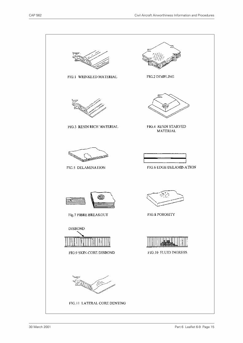
CAP 562 Civil Aircraft Airworthiness Information and Procedures
Part 6 Leaflet 6-9 Page 1530 March 2001

INTENTIONALLY LEFT BLANK