ldhrblt ll fr ldn ntt - springer · pdf fileldhrblt ll fr ldn ntt. . brnd flr rrh nttt, t p,...
TRANSCRIPT

U
W
WaWw
O°PALLADIUM
1.0
GOLD
A Gold-Chromium-Cobalt Alloyfor Sliding Contacts
E. A. BrandesFulmer Research Institute, Stoke Poges, England
A gold base alloy has been developed which can be precipitationhardened to make it suitable for use in sliding contacts. It is hard,strong and wear-resistant and has a low resistivity as well as a lowcontact resistance. The temperature coefficient of resistance can bevaried and can be made low or zero at temperatures in the range
0 to 100°C. Its development is summarised and its properties
compared with those of alloys generally used for sliding contacts.
A sliding electrical contact should be of low andconstant resistance. It should not tarnish, wear orform insulating films by polymerisation of organicmaterial. Pure gold does not oxidise or catalyseorganics, but it wears quickly and then gives erraticvalues for contact resistance. Gold has low contactresistance compared to that of other precious metals,as can be seen by values given by H. C. Angus (1)and E. M. Wise (2) plotted in Figure 1 for increasingloads. The relation between load and resistance in acontact is complex, a full treatment being given byR. Holm (3). He finds that the slope of the curves
plotted as in Figure 1 are similar for most metals sothat, from a single point, an estimate of the probablerelation with load can be obtained.
A satisfactory gold-based contact alloy needs theincreased hardness which can be achieved by alloyingwithout loss of tarnish resistance and with minimumlowering of electrical conductivity. This combinationof properties can be obtained by exploiting precipita-tion hardening in a system in which hardness andstrength can result from the dispersion of a fineprecipitate, leaving a solute-depleted matrix of vir-tually pure gold. In these circumstances, the con-
10 100 1000
LOAD g FORCE
Fig. 1 (above) Resistivity of crossed wire contactsas a function of contact pressure (1, 2)
Fig. 2 (right) The gold-chromium equilibriumdiagram after E. Raub
WEIGHT PER CENT CHROMIUMAu 10 20 40 60 80 Cr
Au 20 40 60 80 CrATOMIC PER CENT CHROMIUM
73
ATOMIC PER CENT COBALT
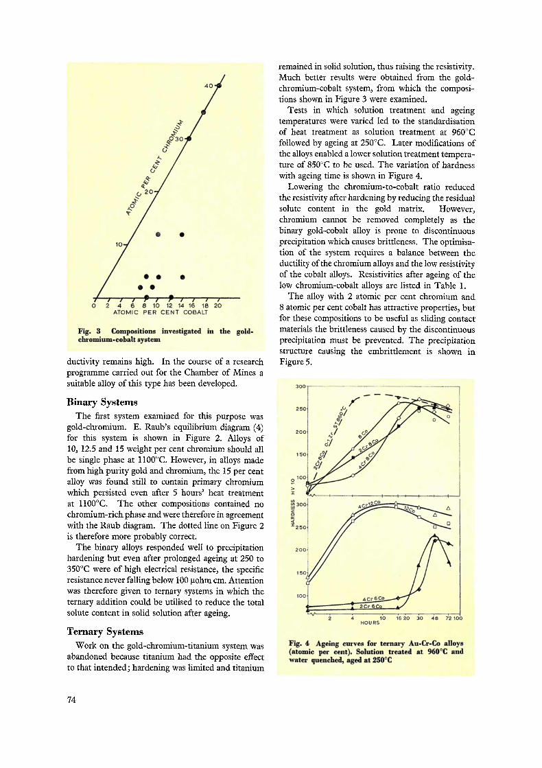
Fig. 3 Compositions investigated in the gold-chromium-cobalt system
ductivity remains high. In the course of a researchprogramme carried out for the Chamber of Mines asuitable alloy of this type has been developed.
Binary SystemsThe first system examined for this purpose was
gold-chromium. E. Raub's equilibrium diagram (4)for this system is shown in Figure 2. Alloys of10, 12.5 and 15 weight per cent chromium should allbe single phase at 1100°C. However, in alloys madefrom high purity gold and chromium, the 15 per centalloy was found still to contain primary chromiumwhich persisted even after 5 hours' heat treatmentat 1100°C. The other compositions contained nochromium-rich phase and were therefore in agreementwith the Raub diagram. The dotted line on Figure 2is therefore more probably correct.
The binary alloys responded well to precipitationhardening but even after prolonged ageing at 250 to350°C were of high electrical resistance, the specificresistance never falling below 100 Rohm cm. Attentionwas therefore given to ternary systems in which theternary addition could be utilised to reduce the totalsolute content in solid solution after ageing.
Ternary SystemsWork on the gold-chromium-titanium system was
abandoned because titanium had the opposite effectto that intended; hardening was limited and titanium
remained in solid solution, thus raising the resistivity.Much better results were obtained from the gold-chromium-cobalt system, from which the composi-tions shown in Figure 3 were examined.
Tests in which solution treatment and ageingtemperatures were varied led to the standardisationof heat treatment as solution treatment at 960°Cfollowed by ageing at 250°C. Later modifications ofthe alloys enabled a lower solution treatment tempera-ture of 850°C to be used. The variation of hardnesswith ageing time is shown in Figure 4.
Lowering the chromium-to-cobalt ratio reducedthe resistivity after hardening by reducing the residualsolute content in the gold matrix. However,chromium cannot be removed completely as thebinary gold-cobalt alloy is prone to discontinuousprecipitation which causes brittleness. The optimisa-tion of the system requires a balance between theductility of the chromium alloys and the low resistivityof the cobalt alloys. Resistivities after ageing of thelow chromium-cobalt alloys are listed in Table 1.
The alloy with 2 atomic per cent chromium and8 atomic per cent cobalt has attractive properties, butfor these compositions to be useful as sliding contactmaterials the brittleness caused by the discontinuousprecipitation must be prevented. The precipitationstructure causing the embrittlement is shown inFigure 5.
2 4 10 1620 30 48 72 100HOURS
Fig. 4 Ageing curves for ternary Au-Cr-Co alloys(atomic per cent). Solution treated at 960 °C andwater quenched, aged at 250°C
74

Table
Resistivity and Hardness of Au-Cr-Co Alloys in Various Conditions
Composition Condition
Cr Co Solution Treated 960°CWQ Solution Treated and Aged 250°C
At Peak Aged 72 HoursAtomic Weight Atomic Weight Resistivity Hardness
Resistivity Hardness Resistivity Hardnessper cent per cent per cent per cent µohm cm HV1 0ohm cm
31.0
HV10 ohm cm HV10
4 1.14 6 1.93 46.6 75.6 220 36.7 214
4 1.16 8 2.62 52.2 83 31.2 270 24.1 257
2 0.56 6 1.90 37.2 67.1 23.1 230 30.9 173
2 0.57 8 2.58 44.3 83 18.6 250 14.2 I 250
Quaternary AlloysDiscontinuous precipitation can, in some cases, be
inhibited by trace additions of specific elements. Thetrace addition should have an atomic size 10 to 15 percent larger than that of the matrix element, and thushave fairly limited solubility in the matrix. In thesecircumstances it will preferentially segregate to thegrain boundary. The ternary composition of gold-2 atomic per cent chromium-8 atomic per centcobalt was chosen as a base to which these traceadditions were made. The elements investigated weremagnesium, indium, lithium, antimony, and zircon-ium at 0.1 atomic per cent additions. Yttrium andcerium were added at the 0.01 atomic per cent level.All of these additions had the effect of acceleratingthe onset of precipitation hardening during ageing at250°C; however, their influence on the control ofdiscontinuous precipitation, varied considerably.
The most successful alloys were those withyttrium which could be hardened to 200HV10 with-out any appearance of grain boundary migration, and
Fig. 5 Discontinuous grain boundary precipitation in agold-4 atomic per cent chromium-8 atomic per centcobalt alloy after solution treatment at 960°C, waterquenching and ageing for 30 hours at 250°C X 250
those with zirconium which could be hardened to atleast 250 HV10 with boundaries free from discon-tinuous precipitation.
After ageing 16 hours at 250°C, the hardness of thezirconium-containing alloy was 276 HV10 and itsgrain boundaries were free of discontinuous pre-cipitation, while the same composition without tracealloy addition had a hardness of 213 HV 10 and showedgrain boundary thickening which heralds the onsetof discontinuous precipitation. Grain boundaryconditions of the alloys with magnesium, yttrium andzirconium trace additions are illustrated by themicrostructures in Figure 6. The effect of thezirconium addition on hardening during ageing isshown for the Au-2Cr-8Co alloy, with and withoutzirconium, in Figure 7. The solution treatmenttemperature of 960°C was found to give large grainsizes; reducing this to 850°C had little effect on thehardening during ageing but was beneficial in pre-venting excessive grain growth.
The progress of selection from binary to quaternarysystems led to the final choice of the preferred com-position alloy, identified as J275, which contains2 atomic per cent chromium, 8 atomic per cent cobaltand 0.1 atomic per cent zirconium (0.6 weight percent chromium, 2.6 weight per cent cobalt and 0.05weight per cent zirconium).
Assessment of the Preferred AlloyApart from the hardness values already shown in
Figure 7, tensile tests on alloy J275 were made on0.25 mm diameter wires 10 cm long. The elongationsvaried from 0.1 to 2.0 per cent, depending on surfacefinish. The 0.1 per cent proof stress and the ultimatetensile strength for various heat treatment conditionsare shown in Table II.
Electrical ResistanceThe electrical resistance of the preferred quaternaryalloy J275 decreases on ageing to about 22 tohm cm.
75
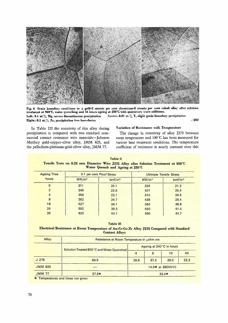
Fig. 6 Grain boundary conditions in a gold-2 atomic per cent chromium-8 atomic per cent cobalt alloy after solutiontreatment at 960°C, water quenching and 16 hours ageing at 250°C with quaternary trace additions.
Left: 0.1 at.% Mg, severe discontinuous precipitation Centre: 0.01 at.% Y, slight grain boundary precipitation
Right: 0.1 at.% Zr, precipitation free boundaries ><250
In Table III the resistivity of this alloy duringprecipitation is compared with two standard com-mercial contact resistance wire materials—JohnsonMatthey gold-copper-silver alloy, JMM 625, andthe palladium-platinum-gold-silver alloy, JMM 77.
Variation of Resistance with Temperature
The change in resistivity of alloy J275 betweenroom temperature and 100°C has been measured forvarious heat treatment conditions. The temperaturecoefficient of resistance is nearly constant over this
Table II
Tensile Tests on 0.25 mm Diameter Wire J275 Alloy after Solution Treatment at 850 °CWater Quench and Ageing at 250 °C
Ageing Time 0.1 per cent Proof Stress Ultimate Tensile Stress
hours MN/m2 tonf/in2 MN/m2 tonf/in2
0 311 20.1 329 21.3
2 349 22.6 407 26.4
4 356 23.1 410 26.5
8 382 24.7 438 28.4
16 527 34.1 569 36.8
24 592 38.3 640 41.4
30 620 40.1 690 44.7
Table III
Electrical Resistance at Room Temperature of Au-Cr-Co-Zr Alloy J275 Compared with StandardContact Alloys
Alloy Resistance at Room Temperature in µohm cm
Solution Treated 850°C and Water QuenchedAgeing at 240°C in hours
4 8 10 40
J 275 43.5 39.8 37.2 29.0 22.2
JMM 625 — 14.0* at 250HV10
JMM 77 37.5* 33.4*
it Temperatures and times not given
76
Table IVContact Resistances for J275 Compared with Standard Alloy Sliding Resistance Materials
Substrate Cupro-Nickel, Rubbing Speed 8cm/s, Load 15g Force, Resistance in mohm. Running Times 40-72 hours
Alloy J275Au-Co-Cr-Zr
JMM 77Pd-Pt-Au-Ag
JMM 625Au-Cu-Ag
Condition Solution Treated Solution Treated Solution Treated Hardness850°C W.Q. Aged 210HV W.Q. Aged 450°C 250HV10
250°C 30 h. 270HV 2 h. 320HV
Maximum contact 15 20 21 440resistancemeasured
Minimum contact 8 10 7 8resistancemeasured
Range 7 10 14 432Number of readings 12 12 5 12Mean reading 10 14 14 127Standard mean 2.1 3.1 5 164
deviation
range, and depends very critically on heat treatment.The alloy in the solution-treated condition has anegative coefficient; ageing at progressively highertemperatures producing increasingly positive co-efficients. Ageing for 2 hours at 250°C after solutiontreatment produces a material with practically nochange in resistance from room temperature to 100°C.This might be a valuable property for some applica-tions. The percentage changes of resistance for arange of heat treatments are plotted in Figure 8.
Sliding Contact Resistance
The apparatus used for measuring the slidingcontact resistance was similar to that described byH. C. Angus (1). It consisted of a 56/44 cupro-nickel cylinder rotated at 60 revolutions per minuteagainst which gold wires were pressed at a fixed load.The roller was 1 inch (2.54 cm) diameter giving awiping speed of 8.0 cm/s. In most of the tests a 15gloading force was used. The springs acted as currentconnections and very light copper wires were spotwelded on near the contacts to act as potential leads.The tests were run for times up to 72 hours, readingsbeing taken at increasing intervals during the run.
The range, average and standard mean deviation ofthe results for the alloy J275 fully heat treated andfor some standard contact wires are shown in TableIV.
These tests showed that as a sliding contactmaterial the new alloy compared well with presentlyavailable alloy wires.
Some initial tests were made against a gold-platedroller. At 3 gram force load, generally low (2 to8mohm) contact resistances were obtained butreadings were very erratic. This was due to the pick-up of the soft gold plate on to the harder contact wire.At 15g force the wires rapidly cut through the softgold plate, and the tests were therefore abandoned.
SolderabilitySolderability was assessed by means of the G.E.C.
Meniscograph Mk3 solderability tester. Thisrecorded the force acting on a wire dipped into a
300 ---
250 /2Cr8Co 0.1 Zr ` \
2002 Cr 8 Co
98if // Ageing at 250 °C
5O — —2 4 10 16 20 30 48 72100
AGEING TIME IN HOURS
Fig. 7 Age hardening of a gold-2 atomic per centchromium-8 atomic per cent cobalt alloy with andwithout 0.1 atomic per cent zirconium. The zirconiumfree alloy was solution treated at 960°C and waterquenched; the zirconium-containing alloy solutionwas treated at 850°C and water quenched
77

1.5.1 ST 24h 250 ° C
1O i ST16h 250 °C
05]
ST Sh 250°C
ST 2 h 250 ° C
I ST only i051
in 20 30 40 50 60 70 80 90 7oCTEMPERATURE • C
Fig. 8 Change of room temperature resistance up to100°C for various heat treatments of the gold-chromium-cobalt-zirconium alloy J275
molten bath of 60/40 solder at 235°C in the presenceof a non-activated 25 per cent resin flux. Initially anup-thrust on the wire is recorded as the wire de-presses the surface of the liquid without wetting, i.e.the meniscus is pushed down; this is shown as anegative reading. As wetting takes place the meniscusgradually comes up to an equilibrium position andduring this stage the reading becomes positive andapproaches a steady value. A reasonable wetting timeis taken as 2 seconds and all the results are thereforegiven as the force in micronewtons experienced bythe wire 2 seconds after immersion. Several dips weremade for each wire condition, and the results are
averages. Usually the repeats were close together.Variable results are noted. Tests were made foruntreated wires, and for the same wires after etchingin 50/50 hydrochloric acid/water at 20°C for 15 secondsfollowed by washing and drying, and for an alkalielectrolytic etch with the wire as cathode at 4A/dm 2
for 5 minutes at 20°C. The cathodic etch was fol-lowed by an anodic etch at 1A/dm 2 at 20°C. for 1second, followed by washing.
The solderability results are set out in Table V.The solution-treated alloy has a solderability com-
parable with that of pure gold but this decreases onageing up to 16 hours at 250°C and then becomesslightly better. The electrolytic etch to remove anychromic oxide film formed during heat treatmentimproved solderability. The solderability revealed bythe test is not high but no difficulty was found inpractice with making soldered joints, as for instancethose that were required in setting up the contactresistance tests. A few solderability tests were madeon the zirconium-free alloy; apart from a somewhatgreater scatter, they did not differ from those for thequaternary alloy.
Summary of Properties
The most promising alloy developed for slidingcontact applications, known as Alloy J275, hastherefore the following properties.
It contains 0.6 weight per cent chromium, 2.6weight per cent cobalt, and 0.05 weight per centzirconium, balance gold.
Its solution treatment involves heating to 850°C,water quenching and ageing for 30 hours at 250°C.If the solution treatment is carried out in air somesurface oxide may need to be removed.
Its resistivity at room temperature when given this
Uz
a0I000
3,xU
Table V
Solderability as Force in µN 2 Seconds after Dipping into 60/40 Solder at 235 °CNon-activated Resin Flux
Wire Condition Force µN (upthrust negative)
Untreated Hydrochloric Electrolytic
Etch Etch
Gold As drawn 257 195 300
Annealed 305 285 253
Alloy Solution treated 850°C W.Q. 228 210 93
J 275 ST+2 h. 250°C 90 125 220*
ST+8 h. 250°C —68 50 0
ST+16 h. 250°C —170 —65 —70
ST+24 h. 250°C —125 —100* I +50
* Means of rather scattered results
78

heat treatment is about 24 4ohmcm. The change ofresistance with temperature depends very much on theheat treatment given. For the above heat treatmentthe change from room temperature to 100 °C will beabout 1.5 per cent. For about 2 hours ageing at250°C the change over this temperature interval isvery small.
Tested against a moving cupro-nickel substratewith a contact force of 15 g, the contact resistance was10 milliohms. This value was reproducible since thestandard deviation of 12 results was 2.1 milliohms.
The solderability of the alloy was very dependentupon ageing time. Tests showed the solderabilityof the fully aged material to be poor compared withpure gold, but in practice soldered joints could bemade easily by hand.
For the heat treatment given above the hardness isabout 270 Vickers. The 0.1 per cent proof stress forthis heat treatment is 620 MN/m2 (40.1 tonf/in2) andthe ultimate tensile strength is 690 MN/m 2 (44.7tonf/in2). Elongation has not been determined.
Brittleness results from too high a solution treatmenttemperature or from excessive grain growth.
ConclusionA gold alloy has been developed which because of
its response to precipitation heat treatment can bemade particularly suitable as a sliding contact. It ishard, strong, and wear-resistant, has a low contactresistance and resistivity and at room temperature it iscompletely tarnish-resistant. The temperature co-efficient of resistance is well characterised and in someheat treatment conditions can be made very low orzero for temperature fluctuations around ambient.
References1 H. C. Angus, Trans. Inst. Metal Finishing, 1962, 39, 12 E. M. Wise, "Gold", D. van Nostrand Co, New York,
19643 R. Holm, "Electric Contacts", Springer Verlag, Berlin
19674 E. Raub, Z. Metallkunde, 1960, 51, 290
Gold Brazing in the Space Shuttle Engines
The production of the three main engines for thespace shuttle is now nearing completion by theRocketdyne Division of Rockwell International atCanoga Park, California, under a contract from theNational Aeronautics and Space Administration.
While a number of joints are electron-beam ortungsten-arc welded, many thousands of assemblieshave been furnace brazed in a hydrogen atmospherewith several types of gold brazing alloys to ensurehigh strength and resistance to corrosion.
Inconel 625 was chosen for a number of components,including the main injection elements, and these werebrazed with 70 Au-22 Ni-8 Pd alloy, while the 304 Lstainless steel parts of the injector face plate were
previously sub-assembled by brazing with 50 Au-25Ni-25 Pd alloy.
The nozzle assembly is constructed from 1086tapered and shaped tubes in a high nickel austeniticstainless steel, brazed together as a unit and supportedby bands of Inconel 718 with Inconel 903 structuralrings. Ageing cycles to develop the full properties ofthese alloys imposed the need for several stages ofbrazing at various temperatures, the alloys used rangingfrom 70 Au-22 Ni-8 Pd to 18 Au-25 Mn-6 Pd-6 Ni-45Cu. Over 15 pounds of these alloys were used to joinmore than 10,000 feet of tubing to the Inconel jacket,with a further 2160 brazed joints where the tube endswere attached to the manifold.
A full-scale mock-up of thespace shuttle orbiter, a winged,manned vehicle about the sizeof a DC9 aircraft. Gold alloybrazing has been used exten-sively in the assembly of thethree main engines
79