lca13: technical overview of big.little switcher
TRANSCRIPT
In Kernel Switcher: A solution to support ARM's new big.LITTLE technology
web: www.linaro.org email: [email protected]
Presenter: Mathieu Poirier
Slide 2
What is big.LITTLE?
● A system that contains two sets of architecturally identical CPUs.
● CPUs differ in the power and performance they yield.
● Similar architecture allows to:○ Run the same software transparently on all CPUs.○ Migrate from one CPU to another transparently.
www.linaro.org email: [email protected]
Slide 2
TC2 - ARM's big.LITTLE implementation
● Has a cluster of Cortex-A15 processors (big) and a cluster of Cortex-A7 processors (LITTLE) in the same system.
● Cortex-A7 and A15 are architecturally similar - ARM v7A.
● Processor caches are kept coherent using a cache coherent interconnect (CCI-400 on TC2).
● A shared Generic Interrupt Controller(GIC-400 on TC2) is used to migrate interrupts between any cores in the big or LITTLE clusters.
www.linaro.org email: [email protected]
Slide 2
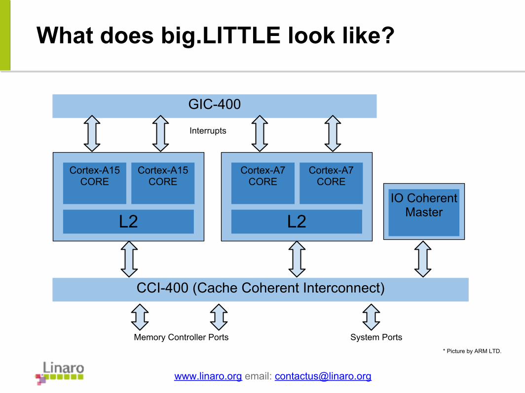
What does big.LITTLE look like?
www.linaro.org email: [email protected]
GIC-400
CCI-400 (Cache Coherent Interconnect)
Cortex-A15 CORE
Cortex-A15 CORE
L2
Cortex-A7 CORE
Cortex-A7 CORE
L2IO Coherent
Master
Interrupts
Memory Controller Ports System Ports* Picture by ARM LTD.
Slide 3
What is the idea behind big.LITTLE?
● Provide a balance between performance and power efficiency.
● The original idea was to use the A15 cluster for CPU intensive task and the A7 cluster for low power task.
○ Gaming - A15○ Web page rendering: A-15○ Texting - A7○ Email - A7
● Linaro's approach is to use system load to decide which core to use.
www.linaro.org email: [email protected]
Slide 3
What is being done at Linaro
● We currently have 2 big.LITTLE projects:○ Heterogenous Multi Processing (HMP).○ In Kernel Switcher (IKS).
● We can switch between them on the fly !
○ IKS can be enabled in the kernel config.○ Or on the kernel command line.○ Or at run time from sysfs.
www.linaro.org email: [email protected]
Slide 3
Heterogeneous Multi Processing (HMP)
● All cores in the system can be used at the same time.
● Scheduler needs to be aware of different CPU processing power when scheduling.
● Higher peak performance for some workloads but harder scheduling problem for the kernel.
● Currently being developed in collaboration with the community.
www.linaro.org email: [email protected]
Slide 3
In Kernel Switching(IKS) at Linaro
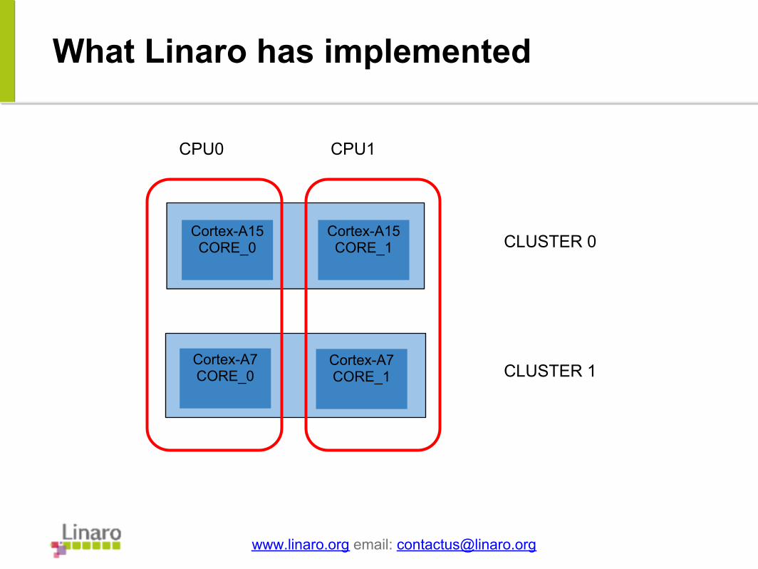
● A7 and A15 CPU from each cluster are coupled together to form a "virtual" CPU.
● All virtual CPUs have the same processing capabilities.● The kernel core doesn't need to know about the
asymmetric nature of the b.L architecture.
● Only one core is active in a given virtual CPU. ● Decision to move from one core to another is taken at the
CPUfreq driver level.● Released to Linaro partners in December of 2012.
www.linaro.org email: [email protected]
Slide 2
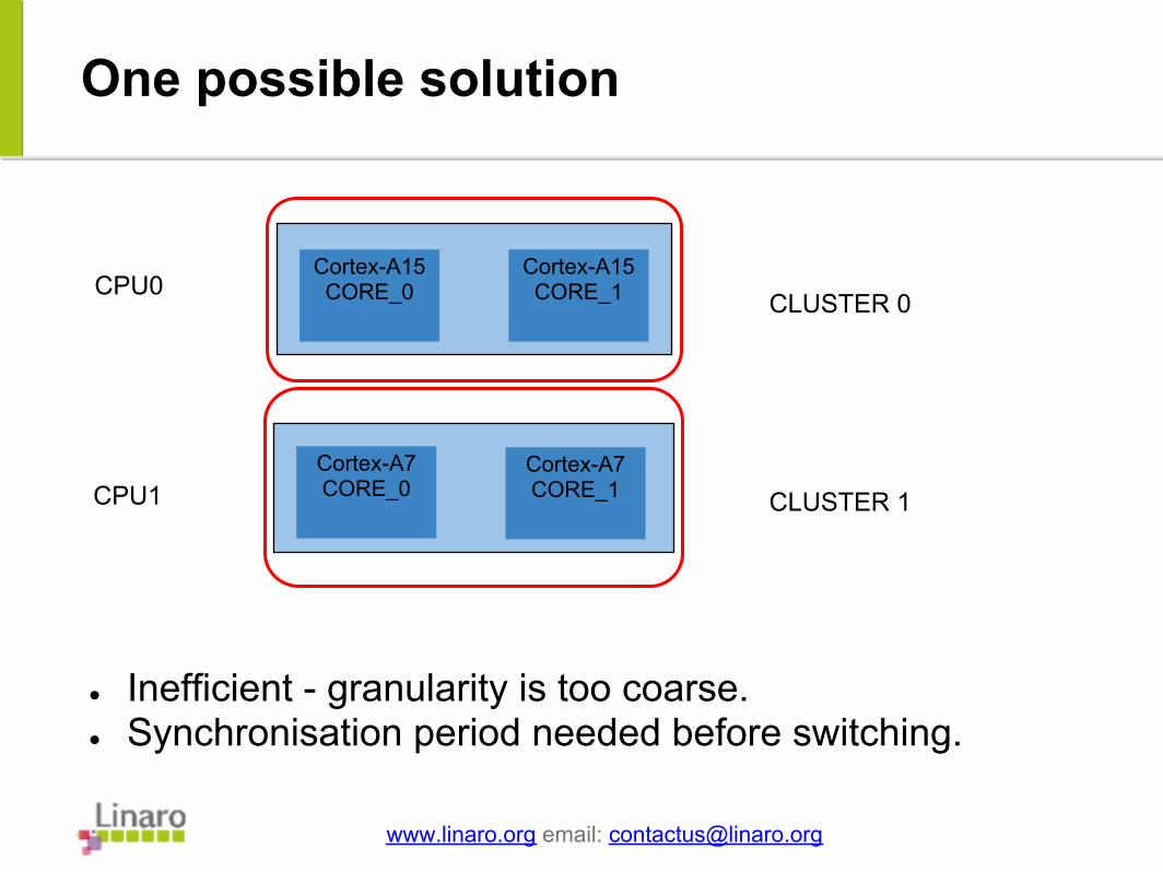
One possible solution
www.linaro.org email: [email protected]
CLUSTER 0
CLUSTER 1
CPU0
CPU1
● Inefficient - granularity is too coarse.● Synchronisation period needed before switching.
Cortex-A15 CORE_0
Cortex-A15 CORE_1
Cortex-A7 CORE_0
Cortex-A7 CORE_1
Slide 2
What Linaro has implemented
www.linaro.org email: [email protected]
Cortex-A15 CORE_0
Cortex-A15 CORE_1
Cortex-A7 CORE_0
Cortex-A7 CORE_1
CLUSTER 0
CLUSTER 1
CPU0 CPU1
Slide 3
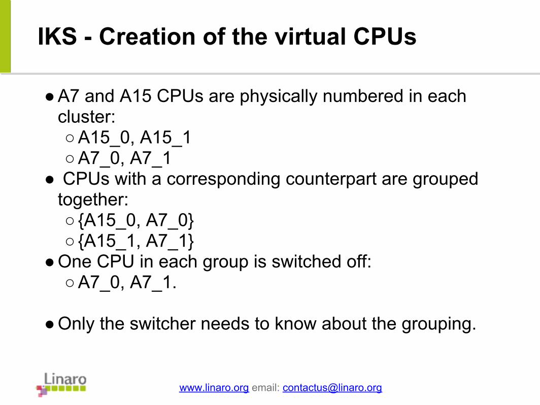
IKS - Creation of the virtual CPUs
● A7 and A15 CPUs are physically numbered in each cluster:○ A15_0, A15_1○ A7_0, A7_1
● CPUs with a corresponding counterpart are grouped together:○ {A15_0, A7_0}○ {A15_1, A7_1}
● One CPU in each group is switched off:○ A7_0, A7_1.
● Only the switcher needs to know about the grouping.
www.linaro.org email: [email protected]

Slide 3
IKS - CPUfreq driver initialisation
● The cpufreq driver deals with the physical characteristic of each CPU core.
● Responsible of presenting the virtual CPUs' operating frequencies to the kernel.
● Select which core in a virtual CPU will be used.
● Also determines when to switch from one core to another in the "virtual" CPU.
● Switcher logic needs to be coordinated with cpufreq driver.
www.linaro.org email: [email protected]
Slide 3
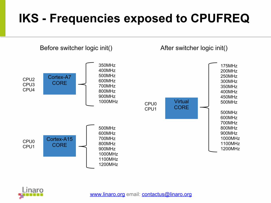
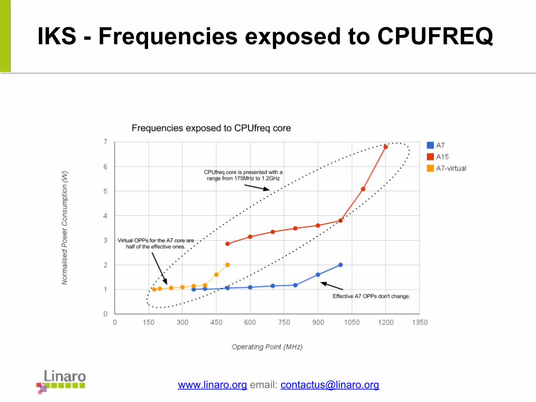
IKS - Frequencies exposed to CPUFREQ
www.linaro.org email: [email protected]
Cortex-A15 CORE
Cortex-A7 CORE
350MHz400MHz500MHz600MHz700MHz800MHz900MHz1000MHz
500MHz600MHz700MHz800MHz900MHz1000MHz1100MHz1200MHz
CPU2CPU3CPU4
CPU0CPU1
Virtual CORE
175MHz200MHz250MHz300MHz350MHz400MHz450MHz500MHz
500MHz600MHz700MHz800MHz900MHz1000MHz1100MHz1200MHz
CPU0CPU1
Before switcher logic init() After switcher logic init()
Slide 3
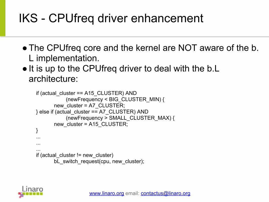
IKS - CPUfreq driver enhancement
● The CPUfreq core and the kernel are NOT aware of the b.L implementation.
● It is up to the CPUfreq driver to deal with the b.L architecture:
www.linaro.org email: [email protected]
if (actual_cluster == A15_CLUSTER) AND (newFrequency < BIG_CLUSTER_MIN) { new_cluster = A7_CLUSTER;} else if (actual_cluster == A7_CLUSTER) AND (newFrequency > SMALL_CLUSTER_MAX) { new_cluster = A15_CLUSTER;} ......... if (actual_cluster != new_cluster) bL_switch_request(cpu, new_cluster);
Slide 3
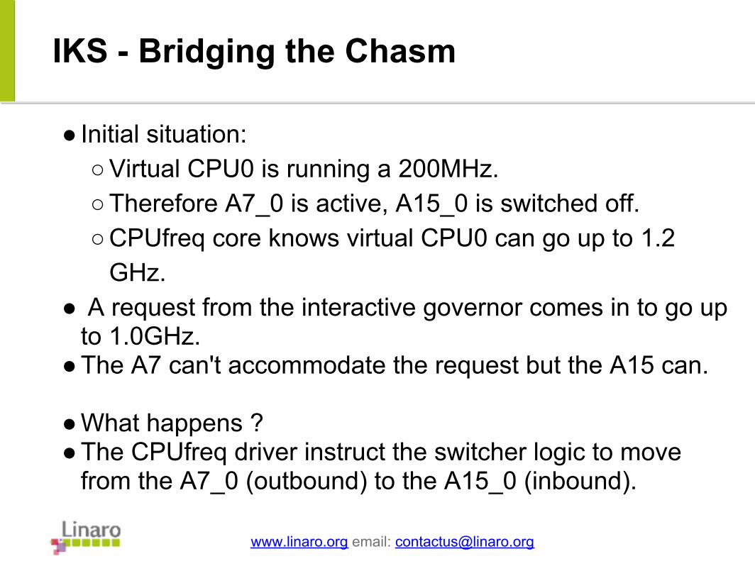
IKS - Bridging the Chasm
● Initial situation:○ Virtual CPU0 is running a 200MHz.○ Therefore A7_0 is active, A15_0 is switched off. ○ CPUfreq core knows virtual CPU0 can go up to 1.2
GHz.● A request from the interactive governor comes in to go up
to 1.0GHz.● The A7 can't accommodate the request but the A15 can.
● What happens ? ● The CPUfreq driver instruct the switcher logic to move
from the A7_0 (outbound) to the A15_0 (inbound).
www.linaro.org email: [email protected]
Slide 3
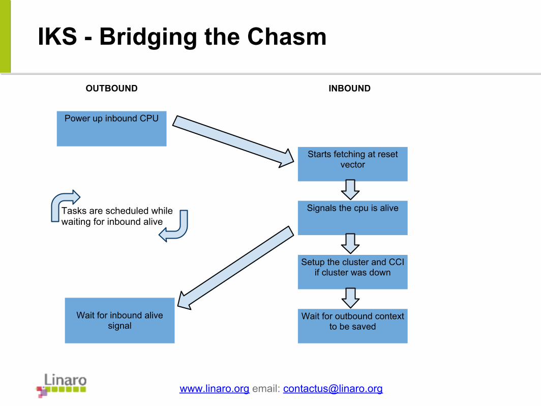
IKS - Bridging the Chasm
www.linaro.org email: [email protected]
Power up inbound CPU
Starts fetching at reset vector
Signals the cpu is alive
Setup the cluster and CCI if cluster was down
Wait for outbound context to be saved
Wait for inbound alive signal
OUTBOUND INBOUND
Tasks are scheduled while waiting for inbound alive
Slide 3
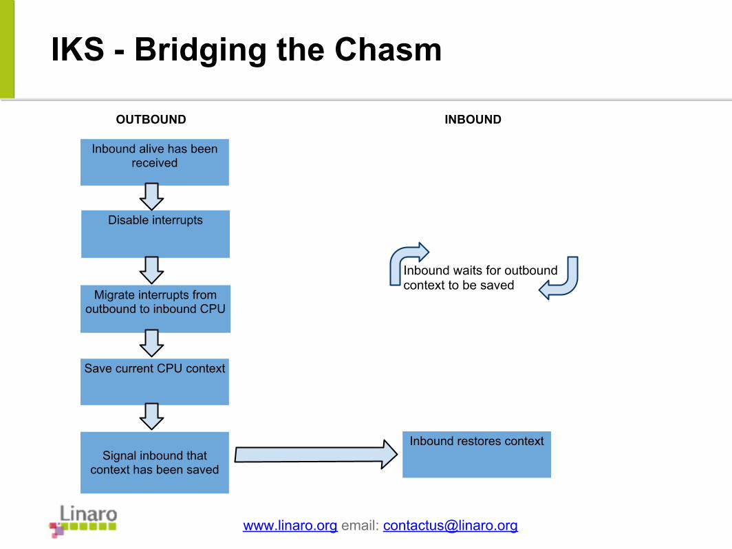
IKS - Bridging the Chasm
www.linaro.org email: [email protected]
Inbound alive has been received
Disable interrupts
Save current CPU context
Signal inbound that context has been saved
Inbound restores context
Migrate interrupts from outbound to inbound CPU
OUTBOUND INBOUND
Inbound waits for outbound context to be saved
Slide 3
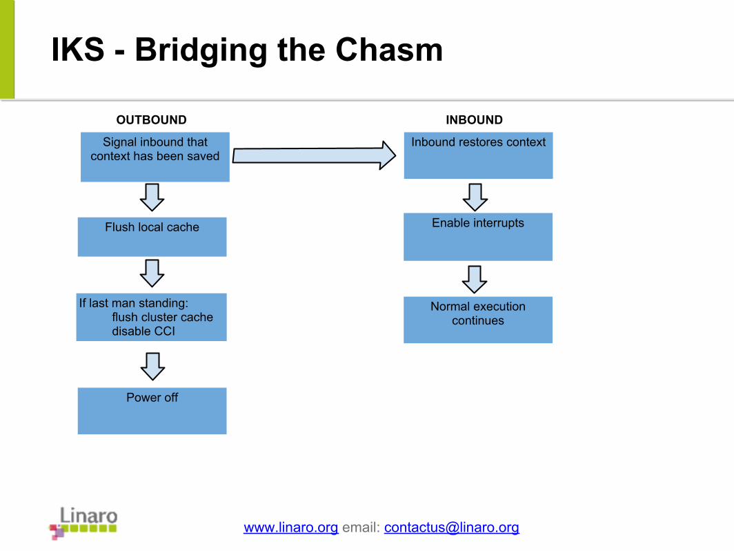
IKS - Bridging the Chasm
www.linaro.org email: [email protected]
Power off
Flush local cache Enable interrupts
Signal inbound that context has been saved
Inbound restores context
If last man standing:flush cluster cachedisable CCI
OUTBOUND INBOUND
Inbound loops on gated address
Normal execution continues
Slide 3
● Important things we haven't mentioned: ○ Mutual exclusion when setting up clusters (vlocks).○ The last man standing algorithm.○ The early poke mechanism.○ CPU and cluster state tracking.
www.linaro.org email: [email protected]
Slide 3
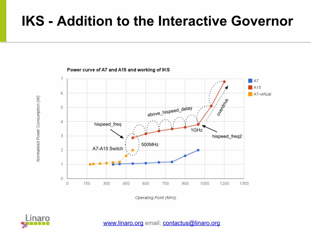
IKS - Addition to the Interactive Governor
● Though generic in nature and not tied to a distribution the IKS solution was tested using Android and the interactive governor.
● In it's original form the interactive governor algorithm reacts to the system load:○ When the system is busy, it jumps to higher
frequencies.○ Above a certain threshold, moving from one OPP to
another is further delayed by a timer. ● Since we have two cores in one virtual CPU, we
duplicated the above algorithm to avoid reaching the overdrive (and costliest) point on the A15.
www.linaro.org email: [email protected]
Slide 3
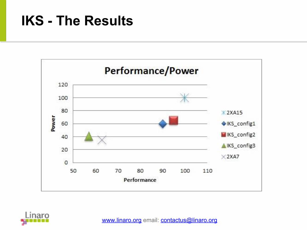
IKS - The Results
● Our metrics:○ Power consumed by each core.○ BBench's "performance" metric, which gives a score for
how fast web pages are loaded. ● Our test:
○ Running BBench with audio playing in the background. ● For IKS our goal was to obtain a 60/90 ratio:
○ 60% of the power used by a 2 x A15 solution.○ 90% of the performance used by a 2 x A15 solution.
www.linaro.org email: [email protected]
Slide 3
IKS - Tuning and Optimisation
● Basic configuration:○ hispeed_freq = Max OPP on A7 = 500MHz○ hispeed_freq2 = Last OPP on A15 before OD = 1GHz○ hispeed_load = 85○ hispeed2_load = 95
● Processing is done on the A7 cluster for as long as the
CPU load is below 85%.● When CPU load is between 85% and 95%, A15 core is
used.● When load goes above 95%, over drive frequencies on
A15 (1.1GHz, 1.2GHz) are reached.
www.linaro.org email: [email protected]
Slide 3
IKS - Tuning and Optimisation
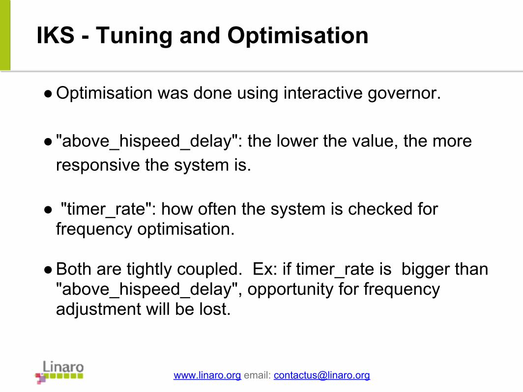
● Optimisation was done using interactive governor. ● "above_hispeed_delay": the lower the value, the more
responsive the system is. ● "timer_rate": how often the system is checked for
frequency optimisation. ● Both are tightly coupled. Ex: if timer_rate is bigger than
"above_hispeed_delay", opportunity for frequency adjustment will be lost.
www.linaro.org email: [email protected]
Slide 3
IKS - Tuning and Optimisation
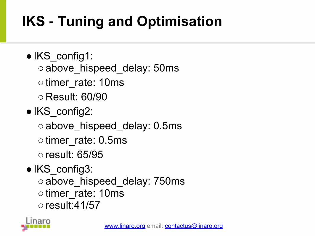
● IKS_config1:○ above_hispeed_delay: 50ms○ timer_rate: 10ms ○ Result: 60/90
● IKS_config2: ○ above_hispeed_delay: 0.5ms○ timer_rate: 0.5ms ○ result: 65/95
● IKS_config3:○ above_hispeed_delay: 750ms○ timer_rate: 10ms ○ result:41/57
www.linaro.org email: [email protected]
Slide 3
IKS - Upstreaming
● Cluster power management is being reviewed on the ARM Linux mailing list and getting positive remarks.
● All the source will be made public when one of our members has a release that utilises this code.
www.linaro.org email: [email protected]
Slide 3
Question and Comments ?
www.linaro.org email: [email protected]
Nicolas PitreDave MartinViresh KumarMathieu PoirierAmit KucheriaDavid ZinmanVishal BhojNaresh KambojuRyan HarkinJohn (Tixy) MedhurstMany others from ARM Ltd.
Contributors to this project: