lc 300 book - support.industry.siemens.com · detergents and pet food. ... Ł field proven and...
TRANSCRIPT

Instruction Manual November 2002
LC 300sitrans

© Siemens Milltronics Process Instruments Inc. 2002
Safety Guidelines
Warning notices must be observed to ensure personal safety as well as that of others, and toprotect the product and the connected equipment. These warning notices are accompaniedby a clarification of the level of caution to be observed.
Qualified Personnel
This device/system may only be set up and operated in conjunction with this manual.Qualified personnel are only authorized to install and operate this equipment in accordancewith established safety practices and standards.
Warning: This product can only function properly and safely if it is correctly transported,stored, installed, set up, operated, and maintained.
Note: Always use product in accordance with specifications.
Copyright Siemens Milltronics ProcessInstruments Inc. 2002. All Rights Reserved
Disclaimer of Liability
This document is available in bound version and inelectronic version. We encourage users topurchase authorized bound manuals, or to viewelectronic versions as designed and authored bySiemens Milltronics Process Instruments Inc.Siemens Milltronics Process Instruments Inc. willnot be responsible for the contents of partial orwhole reproductions of either bound or electronicversions.
While we have verified the contents ofthis manual for agreement with theinstrumentation described, variationsremain possible. Thus we cannotguarantee full agreement. Thecontents of this manual are regularlyreviewed and corrections are includedin subsequent editions. We welcomeall suggestions for improvement.
Technical data subject to change.
MILLTRONICS®is a registered trademark of Siemens Milltronics Process Instruments Inc.
Contact SMPI Technical Publications at the following address:
Technical PublicationsSiemens Milltronics Process Instruments Inc.1954 Technology Drive, P.O. Box 4225Peterborough, Ontario, Canada, K9J 7B1Email: [email protected]
For the library of SMPI instruction manuals, visit our Web site: www.siemens-milltronics.com

1
Table of Contents
Introduction to the SITRANS LC 300 .................................................................................................1
SITRANS LC 300 Applications ..............................................................................................................1SITRANS LC 300 Features ...................................................................................................................1SITRANS LC 300 Outputs .....................................................................................................................1Safety Notes .............................................................................................................................................2The Manual ...............................................................................................................................................2
Technical Specifications: LC 300 ........................................................................................................4
Installation ......................................................................................................................................................7
Location .....................................................................................................................................................7
Configuration and Dimensions ...........................................................................................................8
Rod Version with PFA jacket ................................................................................................................9Cable Version .........................................................................................................................................10Cable Tensile Strength .........................................................................................................................11Shortening the Cable ...........................................................................................................................11
Mounting ........................................................................................................................................................12
Multiple units .........................................................................................................................................12Wall Restriction .....................................................................................................................................12Process Cautions .................................................................................................................................13
Interconnection ..........................................................................................................................................14
Signal Amplifier/Power Supply ..........................................................................................................14Connecting the LC 300 .........................................................................................................................14
Operation .......................................................................................................................................................15
Start Up ....................................................................................................................................................15Position 0 .................................................................................................................................................16Position 1 .................................................................................................................................................16Position 2 .................................................................................................................................................16Position 3 .................................................................................................................................................17Position 4 .................................................................................................................................................18Position 5 .................................................................................................................................................19Recommissioning ..................................................................................................................................19Maintenance ..........................................................................................................................................20
Appendix I: Application Notes ...........................................................................................................21
Application Notes ..................................................................................................................................21
Appendix II: Approvals ...........................................................................................................................22
Instrument Label: SITRANS LC 300 ..................................................................................................24KEMA Certificates and Schedules ...................................................................................................25

2

7ML19985HE01 SITRANS LC 300 � INSTRUCTION MANUAL Page 1
mm
mm
m
Introduction
Introduction to the SITRANS LC 300
The SITRANS LC 300 is a cost-effective instrument for level measurement in high accuracy applications such as the processing of food and beverages, pharmaceuticals, detergents and pet food. It performs in liquids, bulk solids and slurries, including viscous (conductive or non-conductive) materials, even in challenging environments involving vapour and dust.
The LC 300 is a 2-wire instrument combining a sophisticated, yet easy-to-adjust, microprocessor transmitter with field-proven Pointek CLS 300 probes.
The electronic component contains the measurement module (driver) and the microprocessor module. This set of parts forms a calibrated pair, so that readout in pico Farads (pF) is achieved. An optional safety barrier can be included in the electronic component.
The probe comprises a measurement section and an active shield section that is a fixed length. The probe is the primary system sensor, and it indicates the electrical capacitance value of the measurement section relative to the environment (tank wall, stilling well, or conductive material). This part of the probe connects to the capacitance detector in the electronic transmitter.
SITRANS LC 300 Applications� Food, beverages, and water� Liquids, slurries, powders, granules, and solids � Power industry (fly-ash)
SITRANS LC 300 Features � NPT, BSPT, and JIS connections, DIN and ANSI flanges (other connections upon
request) � Corrosion resistant construction, PFA, PEEKTM 1, and 316L stainless steel wetted
parts � 25 m (82 ft) maximum insertion length � Rugged shear and abrasion resistant probe� Fully adjustable range: level, damping, diagnostics, etc.� Field adjustable insertion length for probes without an insulation jacket� Probe input ESD protection to 55 kV continuous discharge� Field proven and patented Active-Shield technology and variable frequency
oscillator
SITRANS LC 300 Outputs � 4 � 20 or 20 � 4 mA, 2�wire current loop circuit� Isolated from the measurement circuit� Current signalling according to NAMUR NE 43
1. PEEK is a registered trademark of Victrex plc.
Page 2 SITRANS LC 300 � INSTRUCTION MANUAL 7ML19985HE01
mm
mm
m
Intr
oduc
tion
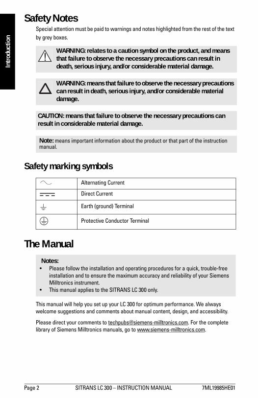
Safety NotesSpecial attention must be paid to warnings and notes highlighted from the rest of the text by grey boxes.
Safety marking symbols
The Manual
This manual will help you set up your LC 300 for optimum performance. We always welcome suggestions and comments about manual content, design, and accessibility.
Please direct your comments to [email protected]. For the complete library of Siemens Milltronics manuals, go to www.siemens-milltronics.com.
WARNING: relates to a caution symbol on the product, and means that failure to observe the necessary precautions can result in death, serious injury, and/or considerable material damage.
WARNING: means that failure to observe the necessary precautions can result in death, serious injury, and/or considerable material damage.
CAUTION: means that failure to observe the necessary precautions can result in considerable material damage.
Note: means important information about the product or that part of the instruction manual.
Alternating Current
Direct Current
Earth (ground) Terminal
Protective Conductor Terminal
Notes:� Please follow the installation and operating procedures for a quick, trouble-free
installation and to ensure the maximum accuracy and reliability of your Siemens Milltronics instrument.
� This manual applies to the SITRANS LC 300 only.

7ML19985HE01 SITRANS LC 300 � INSTRUCTION MANUAL Page 3
mm
mm
m
Introduction
Abbreviations and Identifications
Short form Long Form Description Units
CE / FM / CSAConformitè Europèene / Factory Mutual / Canadian Standards Association
safety approval
DCS Distributed Control System control room apparatus
Ex Explosion Proof
Exd Flame Proof
ESD Electrostatic Discharge
LRV Lower Range Value value for 0 % (in pF) 4 mA
PED Pressure Equipment Directive safety approval
pF pico Farads 10-12 Farad
PV Primary Variable measured value
Stilling WellGrounded metal tube with openings
URV Upper Range Value value for 100% (in pF) 20 mA

Page 4 SITRANS LC 300 � INSTRUCTION MANUAL 7ML19985HE01
mm
mm
m
Spec
ifica
tions
Technical Specifications: LC 300
Power� Supply voltage 9 � 32 Vdc any polarity, 2-wire current loop
(9V @ 22 mA)� Measurement signal 4 � 20 mA or 20 � 4 mA
EnvironmentalLocation indoor/outdoor
Altitude 2000 m max.
Ambient temperature � 40 to 85°C (� 40 to 185°F)
Relative humidity suitable for outdoors (Type 4 / NEMA 4 / IP 65 enclosure)
Installation category II
Pollution degree 4
PerformanceMeasurement range 0 to 3300 pF
Minimum span 3.3 pF
Measurement frequency 600 kHz max.
Accuracy < 0.5% of actual measurement value
Non-linearity and reproducibility < 0.4% full scale and actual measurement value
Temperature stability max. temperature drift of 0.25% of actual capacitance value
Safety - current signalling according to NAMUR NE 43, signal 3.8 to 20.5, fault ≤ 3.6 or ≥ 21 mA (22 mA)- probe input ESD protected to 55 kV- inputs/outputs fully galvanically isolated- polarity-insensitive current loop- wiring connections max. 2.5 mm2, PED / 97 / 23 / EC
Diagnostics1 - primary variable (PV) out of measurement limits- failure in measurement circuit- memory check sum- system watch dog
1. See Fault Values on page 18 for detailed descriptions of Diagnostic messages.

7ML19985HE01 SITRANS LC 300 � INSTRUCTION MANUAL Page 5
mm
mm
m
Specifications
OutputsCurrent loop
� continuous signal 4 to 20 mA / 20 to 4 mA
User InterfaceDisplay
� local LCD 4�digit (each digit can be 0 to 9 or limited alpha characters)
Function rotary switch
� position 0 Actual measurement value (in pF)� position 1 Zero value (LRV) 0% of scale� position 2 Span value (URV) 100% of scale� position 3 Actual mA signal and system fault setting according to
NAMUR NE 43 � position 4 Diagnostic information/Software revision� position 5 Damping
ElectrodesProcess connections
� threaded connections AISI 316 L stainless steel, NPT/BSPT/JIS, ¾�, 1�, 1 ¼� and 1 ½� rod probe connection, 1 ¼� and 1 ½� rope probe connection
� flat-faced flanges AISI 316 L stainless steel, ANSI (1� to 4�), DIN (NW25 to NW100)1
Probe diameter
� rod probes 19 mm/0.75 inch (with or without PFA jacket)� rope probe version 9 mm/ 0.35 inch, with PFA jacket
6 mm/ 0.24 inch, without PFA jacket
Probe lengths
� rod version: min. 300 mm (12") - max. 5000 mm (197")� rope/Cable version: min. 500 mm (20") - max. 25000 mm (984")
Active Shield length
� rod version: 100 mm� rope/cable version: 125 mm
Max. tensile load (rope/cable version)
� 1900kg (4188 lbs)
1. Other process connections available on request. See Probe: Standard on page 9, or Probe: Cable on page 10.

Page 6 SITRANS LC 300 � INSTRUCTION MANUAL 7ML19985HE01
mm
mm
m
Spec
ifica
tions
Max. horizontal tensile load
� 30 Nm (Rod version)
Wetted Parts
AISI 316L/PEEKTM/PFA1
Enclosure (Electronics)� construction aluminium, epoxy coated� ingress protection Type 4 / NEMA 4 / IP65� cable inlet 2 X ½� NPT
WeightDepends on configuration
Process Conditions
Pressure range2 -1 to 35 barg (-14.6 to 511 psig)
Temperature range -40 to 200° C (-40 to 392° F)
Min. dielectric constant (>r): 1.5
Approvals*� CE, CENELEC, FM, CSANRTL/C, ATEX
� Lloyd�s Register of Shipping, categories ENV1, ENV2, and ENV5
*Please verify against device nameplate.
1. For a chemical resistance list for PFA/PEEK, contact your local distributor.2. See the Pressure/Temperature Curve in Appendix I: Application Notes on
page 21.
7ML19985HE01 SITRANS LC 300 � INSTRUCTION MANUAL Page 7
mm
mm
m
Installation
Installation
Location
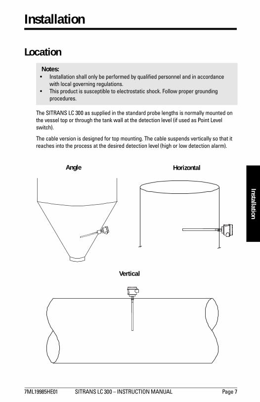
The SITRANS LC 300 as supplied in the standard probe lengths is normally mounted on the vessel top or through the tank wall at the detection level (if used as Point Level switch).
The cable version is designed for top mounting. The cable suspends vertically so that it reaches into the process at the desired detection level (high or low detection alarm).
Notes:� Installation shall only be performed by qualified personnel and in accordance
with local governing regulations. � This product is susceptible to electrostatic shock. Follow proper grounding
procedures.
Angle Horizontal
Vertical

Page 8 SITRANS LC 300 � INSTRUCTION MANUAL 7ML19985HE01
mm
mm
m
Conf
igur
atio
n an
d D
imen
sion
s
Configuration and Dimensions access lid to electronics and operation buttonselectronics (power supply and signal processing)
driversafety barrier (not applicable for General Purpose)aluminum enclosure (Type 4 / NEMA 4 / IP 65)
cable gland, ½� NPT (x2)
thermal isolator (option)
100 mm (4")
PFA insulation125 mm
(4.9") 170 mm (6.7")
25000 mm (985") max.
cable / ropewith PFA jacket-9 mm (0.35")without PFA jacket-6 mm (0.25")
tensile weight
ø 32 mm (1.26")
ø 19 mm (0.75")
5000 mm (200")
Rod, with or without PFA
insulation
100 mm (3.94")

7ML19985HE01 SITRANS LC 300 � INSTRUCTION MANUAL Page 9
mm
mm
m
Configuration and Dim
ensions
Rod Version with PFA jacketC
59 mm (2.3")
76 mm (3")
120 mm (4.7")lid
lid clip
½� NPT
electronics enclosure
active shield100 mm (3.94")
probe
ø19 mm (0.75")
300 to 5000 mm (14 to 197")
145 mm (5.7")

Page 10 SITRANS LC 300 � INSTRUCTION MANUAL 7ML19985HE01
mm
mm
m
Conf
igur
atio
n an
d D
imen
sion
s
Cable VersionC
59 mm (2.3")
76 mm (3")
120 mm (4.7")lid
lid clip
½� NPT
electronics enclosure
active shield125 mm (4.92")
145 mm (5.7") nominal
flexible extension (customer
specified length)
cablewith PFA jacket-9 mm (0.35")
without PFA jacket-6 mm (0.24")
250 mm (9.85")
probe / weight
ø32mm (1.26")
25000 mm (985") max.

7ML19985HE01 SITRANS LC 300 � INSTRUCTION MANUAL Page 11
mm
mm
m
Configuration and Dim
ensions
Cable Tensile Strength
Always confirm that the load carrying capability of the silo/tank roof is sufficient to withstand the actual force on the cable conditions, especially where the force will be, or could be, as great as 1900 kg / 4188 lbs. A cable (rope) probe with a PFA jacket reduces the amount of possible product build-up on the probe as well as the tensile force on the cable.
Shortening the CableMethods
� An angle grinder (preferably with a disc suitable for stainless steel) or
� Wire cutters (suitable for piano cable Ø6 � 9mm).
Procedure
1. Loosen the three set screws and pull weight from the cable.2. Grind/cut the cable to the required length, and then remove rough edges from the
cable.3. Ensure that cable strands are properly seated in the lay of the cable (i.e. no wire
strands sticking outside the normal cable profile). Make sure ALL strands are properly seated before continuing the assembly.
4. Push the weight onto the cable while simultaneously rotating it counter-clockwise around the cable. Make sure that no cable strands are pushed out of their position in the cable and that the cable is fully inserted.
5. Re-fasten the weight by tightening the three set screws.
CAUTION: Do not exceed the tensile strength of the cable at 1900 kg / 4188 lbs.

Page 12 SITRANS LC 300 � INSTRUCTION MANUAL 7ML19985HE01
mm
mm
m
Mou
ntin
g
Mounting
Multiple units
Wall Restriction
End View Side View
500 mm (20") min
500 mm (20") min500 mm (20") min
Sensors must be 500 mm (20") apart. Mount diagonally if vertical space is restricted.
50 mm (2") min 50 mm(2") min
Notes: � These drawings are not to scale.� Distance applies to standard version.

7ML19985HE01 SITRANS LC 300 � INSTRUCTION MANUAL Page 13
mm
mm
m
Mounting
Process Cautions Caution: Keep unit out of path of falling material.
Caution: Consider material surface configuration when installing unit.
500 mm (20") min
Caution: Protect probe from falling material.
Caution: Tensile load must not exceed probe or vessel rating.
Note: Buildup of material in active shield area does not affect the instrument.
Page 14 SITRANS LC 300 � INSTRUCTION MANUAL 7ML19985HE01
mm
mm
m
Inte
rcon
nect
ion
Interconnection
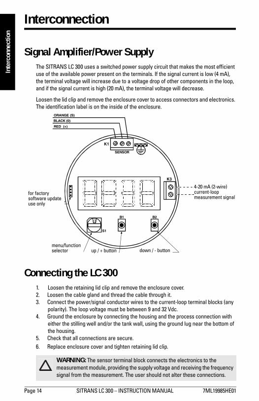
Signal Amplifier/Power SupplyThe SITRANS LC 300 uses a switched power supply circuit that makes the most efficient use of the available power present on the terminals. If the signal current is low (4 mA), the terminal voltage will increase due to a voltage drop of other components in the loop, and if the signal current is high (20 mA), the terminal voltage will decrease.
Loosen the lid clip and remove the enclosure cover to access connectors and electronics. The identification label is on the inside of the enclosure.
Connecting the LC 3001. Loosen the retaining lid clip and remove the enclosure cover.2. Loosen the cable gland and thread the cable through it.3. Connect the power/signal conductor wires to the current-loop terminal blocks (any
polarity). The loop voltage must be between 9 and 32 Vdc.4. Ground the enclosure by connecting the housing and the process connection with
either the stilling well and/or the tank wall, using the ground lug near the bottom of the housing.
5. Check that all connections are secure.6. Replace enclosure cover and tighten retaining lid clip.
WARNING: The sensor terminal block connects the electronics to the measurement module, providing the supply voltage and receiving the frequency signal from the measurement. The user should not alter these connections.
K1
RED (+)
BLACK (0)
ORANGE (S)
SENSOR
CURRENT-LOOPSIGNAL
UP/+ BUTTON DOWN/- BUTTON
MENU/FUNCTIONSELECTOR
0
S1
K3
B2B1
FOR FACTORY SOFTWAREUPDATE USE ONLY
4-20 mA (2-wire) current-loop measurement signal
for factory software update use only
menu/function selector up / + button down / - button
Installation.fm Page 14 Thursday, December 5, 2002 8:38 AM
7ML19985HE01 SITRANS LC 300 � INSTRUCTION MANUAL Page 15
mm
mm
m
Operation
Operation
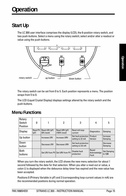
Start UpThe LC 300 user interface comprises the display (LCD), the 6-position rotary switch, and two push-buttons. Select a menu using the rotary switch; select and/or alter a readout or value using the push-buttons.
The rotary switch can be set from 0 to 5. Each position represents a menu. The position wraps from 5 to 0.
The LCD (Liquid Crystal Display) displays settings altered by the rotary switch and the push-buttons.
Menu Functions
When you turn the rotary switch, the LCD shows the new menu selection for about 1 second followed by the data for that selection. When you alter a read-out or value, a colon (:) is displayed when the debounce delay timer has expired and the new value has been accepted.
Positions 0 (Primary Variable in pF) and 3 (corresponding loop-current values in mA) are the recommended positions during normal operation.
Rotary Switch Position
0 1 2 3 4 5
Display Read PV (pF)
Read LRV (pF)(0% level)
Read URV (pF)(100% level)
Read mA loop-current Diagnostics Damping
Up button Increase LRV Increase URV Set fault protection setting to 22 mA
Product Version
Increase Damping
Down button
Decrease LRV Decrease URV Set fault protection setting to 3.6 mA
Decrease Damping
Both buttons
Set LRV from PV Set URV from PV Disable fault protection
Reset/Acknowledge Fault
Set Damping to 1.00
rotary switch up button down button

Page 16 SITRANS LC 300 � INSTRUCTION MANUAL 7ML19985HE01
mm
mm
m
Ope
ratio
n
Position 0
Position 1
Position 2
Display � LCD displays the PV (Primary Variable) in pF.� In case of a system fault, the display alternates between PV value
and Flt. View the fault details in menu 4.� Pressing either or both push-buttons in menu 0 has no effect.
Display � LCD displays the LRV (Lower Range Value) in pF, occurring when the range is at 0% and the loop-current is set to 4 mA.
Up Button
� Pressing Up button for less than 1 second adjusts the LRV in the current step size (initially 0.01 pF).
� Holding the Up or Down buttons for more than 1 second increases the step size to 0.1 pF. If you continue to hold the button, the step size increases to 10, 100, and 1000 (displayed as 1E3). When no button is pressed for 4 seconds, the step size decreases to the next smallest value. At each step size, press the buttons for less than 1 second to adjust the value.
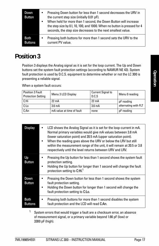
Down Button
� Pressing Down button for less than 1 second decreases the LRV in the current step size (initially 0.01 pF).
� When held for more than 1 second, the Down Button will increase the step size by 0.1, 10, 100, and 1000. When no button is pressed for 4 seconds, the step size decreases to the next smallest value.
Both Buttons
� Pressing both buttons for more than 1 second sets the LRV to the current PV value.
Display � LCD displays the URV (Upper Range Value) in pF, occurring when the range is at 100% and the loop-current is set to 20 mA.
Up Button
� Pressing Up button for less than 1 second adjusts the URV in the current step size (initially 0.01 pF).
� Holding the Up or Down buttons for more than 1 second increases the step size to 0.1 pF. If you continue to hold the button, the step size increases to 10, 100, and 1000 (displayed as 1E3). When no button is pressed for 4 seconds, the step size decreases to the next smallest value. At each step size, press the buttons for less than 1 second to adjust the value.
7ML19985HE01 SITRANS LC 300 � INSTRUCTION MANUAL Page 17
mm
mm
m
Operation
Position 3Position 3 displays the Analog signal as it is set for the loop current. The Up and Down buttons set the system fault protection settings (according to NAMUR NE 43). System fault protection is used by D.C.S. equipment to determine whether or not the LC 300 is presenting a reliable signal.
When a system fault occurs:
Down Button
� Pressing Down button for less than 1 second decreases the URV in the current step size (initially 0.01 pF).
� When held for more than 1 second, the Down Button will increase the step size by 0.1, 10, 100, and 1000. When no button is pressed for 4 seconds, the step size decreases to the next smallest value.
Both Buttons
� Pressing both buttons for more than 1 second sets the URV to the current PV value.
Position 3 Fault Protection Setting
Menu 3 LCD DisplayCurrent Signal to D.C.S
Menu 0 reading
C:Hi 22 mA 22 mA pF reading alternating with FLTC:Lo 3.6 mA 3.6 mA
C:An mA value at time of fault none pF reading
Display � LCD shows the Analog Signal as it is set for the loop-current in mA. Normal primary variables would give mA values between 3.8 mA (lower saturation point) and 20.5 mA (upper saturation point).
� When the reading goes above the URV or below the LRV but still within the measurement range of the unit, it will remain at 20.5 or 3.8 respectively until the level returns between URV and LRV.
Up Button
� Pressing the Up button for less than 1 second shows the system fault protection setting.
� Holding the Up button for longer than 1 second will change the fault protection setting to C:Hi.1
1. System errors that would trigger a fault are a checksum error, an absence of measurement signal, or a primary variable beyond 1.66 pF (low) or 3300 pF (high).
Down Button
� Pressing the Down button for less than 1 second shows the system fault protection setting.
� Holding the Down button for longer than 1 second will change the fault protection setting to C:Lo.
Both Buttons
� Pressing both buttons for more than 1 second disables the system fault protection and the LCD will read C:An.

Page 18 SITRANS LC 300 � INSTRUCTION MANUAL 7ML19985HE01
mm
mm
m
Ope
ratio
n
Position 4
Fault values
Display � LCD shows diagnostic information. A correctly operating device shows 0.00 on the LCD. See chart below for explanation of system fault values.
Up Button
� LCD shows revision information. Please note this information when calling Siemens Milltronics representatives for assistance.
Both Buttons
� Holding both buttons for more than 1 second will try to reset the error status. The LCD reads 0.00 when the status has been successfully reset. Monitor the LC 300 more closely after a diagnostic error has occurred.
128 The device is in calibration mode. The measurement values and the loop-current setting may no longer be trusted.
64 A checksum error has occurred in the program and/or data memory. The measurement values and the loop-current setting may no longer be trusted.
32 The LC 300 system watchdog has been activated. This fault can be combined with fault 64, resulting in fault 96. The measurement values and the loop-current setting may no longer be trusted.
8 An arithmetic error has occurred, perhaps caused by an incorrect value setting. This event type error will rarely affect the operation of the LC 300.
4 An error occurred while trying to store settings in the local non-volatile memory. The LC 300 may not operate correctly.
2 The primary variable has exceeded the device limits (1.66 pF and 3300 pF). Check that the probe is correctly connected to the measurement module.
1 The measurement circuit no longer emits signal. Check the wiring to/from the measurement module or barrier circuit.

7ML19985HE01 SITRANS LC 300 � INSTRUCTION MANUAL Page 19
mm
mm
m
Operation
Position 5
RecommissioningThe LC 300 should be recommissioned whenever the transmitter or probes are replaced.
The LC 300 LRV will be programmed as factory default. The LRV can be re-adjusted in menu 1 when the probe is at least 20 cm away from material.
Display � LCD shows the damping value. The damping value alters the speed at which the primary variable will track the signal from the probe.
Up Button
� Pressing Up button for less than 1 second increases the damping value in 0.01 steps. Damping can be set to any value from 1.0 to 1000.0
� Holding the Up or Down buttons for more than 1 second increases the step size to 0.1. If you continue to hold the button, the step size increases to 10, 100, and 1000 (displayed as 1E3). When no button is pressed for 4 seconds, the step size decreases to the next smallest value. At each step size, press the buttons for less than 1 second to adjust the value.
Down Button
� Pressing Down button for less than 1 second decreases the damping value in 0.01 steps. Damping can be set to any value from 1.0 to 1000.0
� When held for more than 1 second, the Down Button will increase the step size by 0.1, 10, 100, and 1000. When no button is pressed for 4 seconds, the step size decreases to the next smallest value. At each step size, press the buttons for less than 1 second to adjust the value.
Both Buttons
� Holding both buttons for more than 1 second sets the damping value back to 1.0 (default).
Setting URV
If probe is fully covered in application:
Set URV by pressing both buttons for more than 1 second in menu 2 when probe is fully covered.
If probe is rarely or never fully covered, set the LC 300 to your application based on the following example:
LRV (0%) Menu 1 reads 12.5 pF
Actual level is at 45% of the measurement length of probe:
PV (45%) Menu 0 reads 37 pF
The correct setting for URV:
URV = [(PV�LRV) * 100 / actual level in %] + LRV][(37�12.5) * 100 / 45] +12.5= 66.94 pF
When calculating the URV, best results are achieved when using the highest possible actual level.

Page 20 SITRANS LC 300 � INSTRUCTION MANUAL 7ML19985HE01
mm
mm
m
Ope
ratio
n
MaintenanceThe SITRANS LC 300 requires no regular maintenance or cleaning. Even with significant build-up on the SITRANS LC 300 probe, the level controller will continue to operate.
Note: Build-up of material on the active shield area has little or no effect on the performance of the SITRANS LC 300.

7ML19985HE01 SITRANS LC 300 � INSTRUCTION MANUAL Page 21
mm
mm
m
Appendix I
Appendix I: Application Notes
Application Notes Temperature and Pressure Recommendations for Application
Note: 1 bar = 100 Pascals

Page 22 SITRANS LC 300 � INSTRUCTION MANUAL 7ML19985HE01
mm
mm
m
App
endi
x II
Appendix II: Approvals
WRITTEN DECLARATION OF CONFORMITYWe, Siemens Milltronics Process Instruments B.V.
Nikkelstraat 10 - 4823 AB BREDA - The Netherlands
Declare, solely under own responsibility, that the product
Capacitance Level Transmitter, SITRANS LC 300
Mentioned in this declaration, complies with the following standards and/or normative documents:
Requirements Remarks Certificate No
Environment Commercial, light Industrial and industrial 2017488-QUA/EMC 02-4158
EN 61326: 1998 Product group standard for �Electrical equipment for measurement, control and laboratory use�, from which:
EN 55011: 1998 Emission � Class B
EN 61000-4-2: 1995 Electrostatic Discharge (ESD) ImmunityEN 61000-4-3: 1996 Radiated Electro-Magnetic Field ImmunityEN 61000-4-4: 1995 Electrostatic Fast Transient (EFT) ImmunityEN 61000-4-5: 1995 Surge Transient ImmunityEN 61000-4-6: 1996 Conducted Radio-Frequency Disturbances Immunity
ATEX Directive 94/9/EC Audit Report No 2003068 KEMA 00ATEXQ3047
II 1/ 2 GD EEx d [ia] IIC T6�T1 KEMA 00ATEX2040X
0344 T 100 °C IP 66
EN 50014: 1992 General RequirementsEN 50018: 1994 Flameproof Enclosures "d"EN 50020: 1994 Intrinsic Safety �i�EN 50284: 1999 Special Requirements for Category 1G Equipment EN 50281-1-1: 1998 Dust Ignition Proof The notified body: N.V. KEMA � Utrechtseweg 310 � 6812 AR Arnhem � The Netherlands97/23/EC Pressure Equipment Directive Lloyd�s Register, DAD No.:
8033472, 8033473, 8033628The notified body: Stoomwezen B.V. � Weena Zuid 168 � 3012 NC
Rotterdam � The Netherlands
Location: Breda Named Representative: C.S. van Gils
Date: June 19th, 2002 Function: Managing Director
Note: For specific safety specifications, please consult the instrument label.

7ML19985HE01 SITRANS LC 300 � INSTRUCTION MANUAL Page 23
mm
mm
m
Appendix II
SCHRIFTLICHE KONFORMITÄTSERKLÄRUNG
Erklärung der, Siemens Milltronics Process Instruments B.V. Nikkelstraat 10 - 4823 AB BREDA - Niederlande
Wir erklären hiermit auf eigene Verantwortung, dass das
Kapazitive Füllstand Messgerät, SITRANS LC 300
Das Gegenstand dieser Erklärung ist, mit den folgenden Normen und/oder Regelwerken übereinstimmt:
Anforderungen Bemerkungen Zertifizierungs-Nr.
Umwelt Handel, Leichtindustrie und Industrie 2017488-QUA/EMC 02-4158
EN 61326: 1998 Standard Produkt Gruppe für Elektrische Mess- Regel und Laborgeräte bezüglich:
EN 55011: 1998 Störaussendung - Klasse B
EN 61000-4-2: 1995 Überspannungsschutz (ESD) EN 61000-4-3: 1996 Elektromagnettische VerträglichkeitEN 61000-4-4: 1995 Störfestigkeit gegen schnelle TransientenEN 61000-4-5: 1995 Störfestigkeit gegen StoßspannungenEN 61000-4-6: 1996 Störfestigkeit gegen leitungsgeführte Störgrößen
ATEX Richtlinie 94/9/EC Prüfungsbericht Nr 2003068 KEMA 00ATEXQ3047
II 1/ 2 GD EEx d [ia] IIC T6�T1 KEMA 00ATEX2040X
0344 T 100 °C IP 66
EN 50014: 1992 Allgemeine Bestimmungen EN 50018: 1994 Druckfeste Kapselung "dEN 50020: 1994 Eigensicherheit "i"EN 50284: 1999 Besondere Bestimmungen für Betriebsmittel der Kategorie 1G EN 50281-1-1: 1998 Staub-Ex-Sicherheit Benachrichtigte Stelle: N.V. KEMA � Utrechtseweg 310 � 6812 AR Arnhem � Niederlande97/23/EC Richtlinie über Druckgeräte Lloyd�s Register, DAD No.:
8033472, 8033473, 8033628Benachrichtigte Stelle: Stoomwezen B.V. � Weena 168 � 3012 NC
Rotterdam� Niederlande
Ort, Breda Name des Vertreters, C.S. van Gils
Datum, 19 Juni 2002 Stellung, Managing Director
Hinweis: Besondere Sicherheitsangaben finden Sie auf den Typenschild
Page 24 SITRANS LC 300 � INSTRUCTION MANUAL 7ML19985HE01
mm
mm
m
App
endi
x II
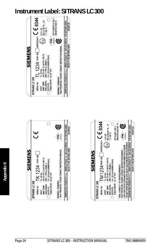
Instrument Label: SITRANS LC 300
7ML19985HE01 SITRANS LC 300 � INSTRUCTION MANUAL Page 25
mm
mm
m
Appendix II
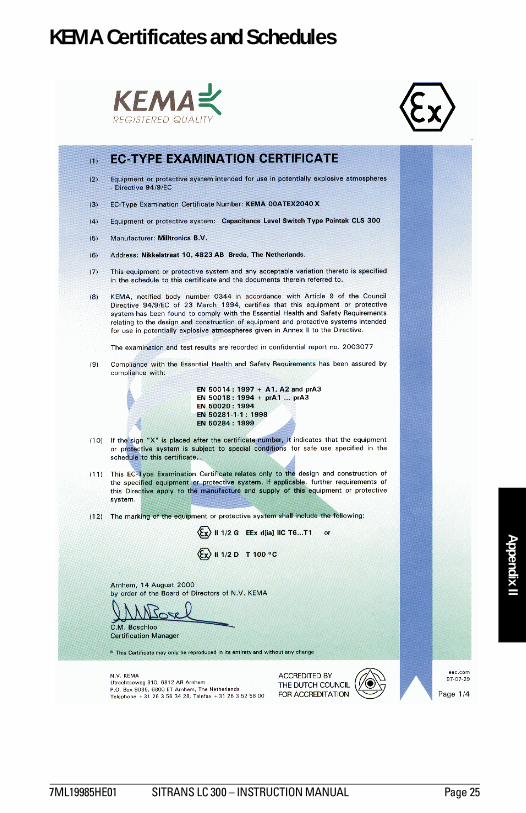
KEMA Certificates and Schedules

Page 26 SITRANS LC 300 � INSTRUCTION MANUAL 7ML19985HE01
mm
mm
m
App
endi
x II

7ML19985HE01 SITRANS LC 300 � INSTRUCTION MANUAL Page 27
mm
mm
m
Appendix II

Page 28 SITRANS LC 300 � INSTRUCTION MANUAL 7ML19985HE01
mm
mm
m
App
endi
x II

7ML19985HE01 SITRANS LC 300 � INSTRUCTION MANUAL Page 29
mm
mm
m
Appendix II

Page 30 SITRANS LC 300 � INSTRUCTION MANUAL 7ML19985HE01
mm
mm
m
App
endi
x II
IndexAabbreviations
list 3accuracy 4analog signal 17appendix
application notes 21approvals 22
application notes 21applications 1approvals 6, 22Bbuild-up 20Ccable
shortening 11tensile strength 11
configuration 8connections 14Ddamping value 19diagnostics 18
fault values 18dimensions 8
cable 10standard 9
display 5Ffault values 18features 1Iidentification label 14identifications
list 3installation
location 7interconnection 14
signal amplifier 14introduction to SITRANS LC 300 1Llower range value 16LRV 16Mmaintenance 20menu
position 0 16position 1 16
position 2 16position 3 17position 4 18position 5 19
mounting 12multiple units 12
Ooperation 15outputs 1Pposition 0 16position 1 16position 2 16position 3 17position 4 18position 5 19power supply 4primary variable 16probes 5process cautions 13process connection 5Rrecommissioning 19Ssignal amplifier 14SITRANS LC 300
applications 1configuration 8features 1outputs 1
start up 15system fault protection 17Ttransmitter 4Uupper range value 16URV 16

*7ml19985HE01*Rev. 1.0
www.siemens-milltronics.com
Siemens Milltronics Process Instruments Inc.
1954Technology Drive, P.O. Box 4225
Peterborough, ON. Canada K9J 7B1
Tel: (705) 745-2431 Fax: (705) 741-0466
Email: [email protected]
Siemens Milltronics Process Instruments Inc. 2002
Subject to change without prior notice
Printed in Canada